
At its core, a wiring diagram for a shunt trip circuit breaker is pretty straightforward. It shows an internal coil wired up to a remote device, which could be anything from an E-stop button to a fire alarm contact.
When that remote device closes the circuit, it shoots a control voltage to the coil. That coil then mechanically forces the breaker to open instantly, cutting power from a safe distance. This is a whole different ballgame compared to a standard breaker, which just sits there waiting to react to overcurrent. With a shunt trip, you're in control.
What a Shunt Trip Circuit Breaker Actually Does
Before you start tracing wires, it's crucial to get why a shunt trip breaker is an absolute non-negotiable in so many industrial safety systems. A standard thermal-magnetic breaker is passive—it only trips after an overcurrent or short circuit has already happened. A shunt trip breaker, on the other hand, acts on command. It gives you a way to kill a circuit immediately and remotely, making it a cornerstone of modern safety protocols.
Think of it as the electrical world's emergency brake. A regular breaker protects the equipment; a shunt trip protects your people and your facility. You'll see them everywhere, from machine shops to complex automated lines. In high-risk fields like those you find in metal fabrication companies, the ability to stop heavy machinery instantly isn't just a feature—it's a necessity.
The Key Players in a Shunt Trip System
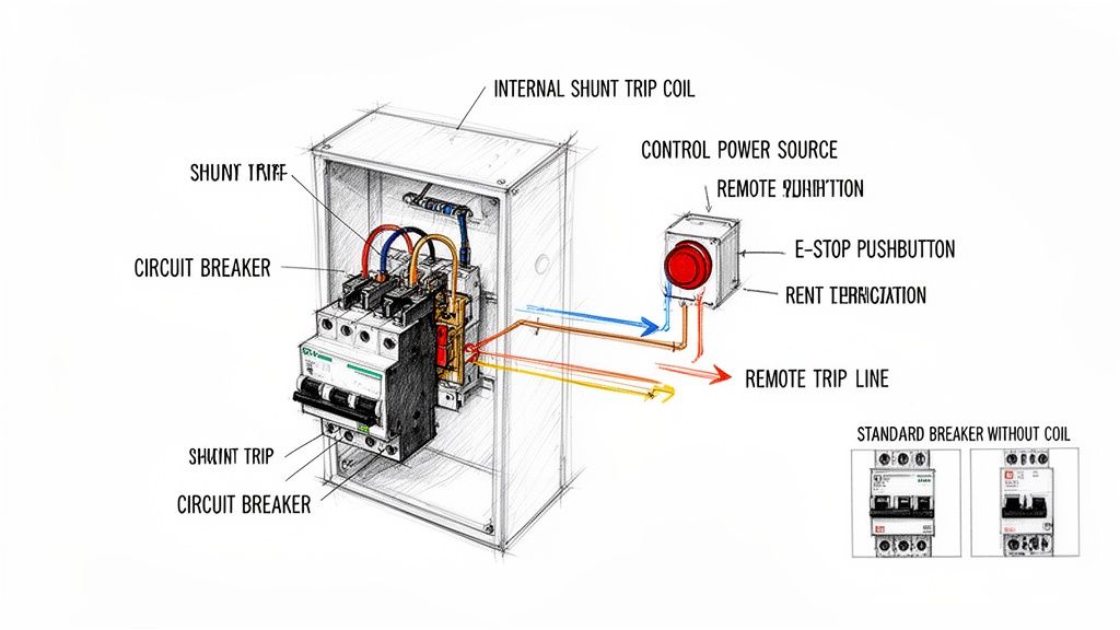
A shunt trip system is really quite simple when you break it down. You’ve just got four main parts working together. Understanding how they interact is the first step to getting the installation right.
- The Circuit Breaker: This is your main device. It has all the standard overcurrent protection but includes an internal port for the shunt trip accessory.
- The Shunt Trip Coil: It's a small solenoid coil that lives inside the breaker. When it gets hit with voltage, it creates a magnetic field that physically shoves the breaker's trip mechanism open.
- The Control Power Source: This is a separate, dedicated power source that supplies the juice—like 24V DC or 120V AC—to activate the coil. It has to be reliable and sized correctly for the job.
- The Initiating Device: This is your trigger. It's usually a normally open (N.O.) contact, like an emergency pushbutton, a relay from a fire alarm panel, or even an output from a PLC.
Shunt Trip vs. The Other Guys
It's easy to get shunt trips, standard breakers, and undervoltage release breakers mixed up. But getting their functions straight is critical if you want to apply and wire them correctly.
A standard breaker is completely passive. It only cares about what’s happening on the main circuit it's protecting and has no external control inputs.
An undervoltage release (UVR) breaker is the exact opposite of a shunt trip. It needs a continuous control voltage just to stay closed and will automatically trip if that voltage is lost. We use these when we don't want a machine to suddenly restart after a power outage.
A shunt trip breaker, however, stays closed until a control voltage is applied to its coil. It’s a "trip on command" device, making it perfect for E-stop circuits where you need deliberate action to cut the power.
Choosing the right coil voltage is a common decision point when designing a control panel. It depends entirely on your control system's standard voltage.
Shunt Trip Coil Voltage Selection for Common Applications
| Coil Voltage | Typical Control Source | Common Industrial Applications | Key Design Consideration |
|---|---|---|---|
| 24V DC | PLC Outputs, Safety Relays, Low-Voltage Control Circuits | Automated machinery, robotics, UL508A control panels | Most common for modern control systems; minimizes shock hazard in the control cabinet. |
| 120V AC | Control Transformers, Lighting Circuits, Fire Alarm Panels | Building automation, HVAC systems, simpler machine controls | Widely available and simple to source, but requires careful routing of AC control wiring. |
| 240V AC | Direct Line Voltage Tap (Phase-to-Phase or Phase-to-Neutral) | Heavy industrial equipment, motor control centers (MCCs) | Can simplify wiring by eliminating a control transformer, but introduces higher voltage into the control circuit. |
| 48V DC | Telecom Power Supplies, Battery Backup Systems | Telecommunications facilities, data centers, substations | Common in DC-powered environments; ensures trip functionality during AC power loss if on a UPS. |
This choice impacts everything from wire sizing to panel layout, so getting it right upfront saves a lot of headaches later.
This foundational knowledge is key for any plant engineer or system integrator trying to build a reliable and code-compliant UL control panel. Being able to remotely and decisively kill power isn't just a nice-to-have; it's a critical safety function. If you're working with specific brands, digging into the features of an ABB circuit breaker and its available accessories is a great next step.
Nailing the Prep Work: Component Selection and Safety Checks
A rock-solid shunt trip installation is built on smart decisions made long before you even touch a wire. Getting the component selection and initial safety checks right from the get-go is everything. It's the difference between a smooth, reliable system and one plagued by costly rework and headaches down the road.
First things first, you need a circuit breaker that’s actually designed to have a shunt trip accessory installed. This isn't a "one-size-fits-all" situation. Always, and I mean always, check the manufacturer's datasheet to confirm compatibility. Trying to force a shunt trip onto a breaker that isn't built for it is a non-starter and a huge safety hazard.
Matching Coil Voltage to Your Control System
One of the most common—and frustrating—mistakes I see in the field is a mismatch between the shunt trip coil's voltage and the control power source. That little coil is just a solenoid, and if you feed it the wrong voltage, it’s either not going to work or you’ll burn it out.
The common options are usually 120V AC, 24V DC, or 24V AC.
Picture this: A beautiful new UL control panel is built around a slick 24V DC PLC system, but someone spec'd a breaker with a 120V AC shunt trip coil. Suddenly, you're scrambling for a last-minute control transformer and running extra wires, blowing up the budget and the timeline. Avoid the pain and confirm your control voltage before you order anything.
Sizing Your Control Wiring and Fuses
Once the voltage is sorted, you've got to size the control wiring and its overcurrent protection correctly. Shunt trip coils are inductive loads, which means they have an inrush current—a big gulp of amperage for a split second when it first energizes. This is a tiny detail that can cause major problems if you ignore it.
Dive back into that manufacturer datasheet and hunt for two key numbers:
- Sealed/Holding Power: The steady power the coil needs (in VA or Watts).
- Inrush Current/VA: The peak power it pulls to activate the trip.
Your control wiring (typically 14-24 AWG) has to handle that inrush spike without a major voltage drop. Even more critical is the fuse or mini-breaker protecting that circuit. It needs to be tough enough to let the inrush current pass without nuisance tripping, but sensitive enough to blow if there's a real overcurrent problem. A fast-acting fuse might pop every time you power up, while an oversized one offers zero protection.
A well-executed shunt-trip setup is a massive safety upgrade. Modern modules can trip a breaker in under 50–150 milliseconds of receiving a signal, allowing automated shutdowns that are lightyears faster than any human. In fact, studies show that up to 20–35% of control panel wiring issues found during commissioning trace back to mismatched control voltages or improperly fused trip circuits. It just shows how critical these upfront decisions really are. Find out more about how breakers work on Wikipedia.
For panel builders and integrators, this kind of meticulous planning is non-negotiable. Our complete guide on industrial control panel design dives even deeper into these principles. Getting these details right from the start is how you build a final UL-listed panel that’s both safe and absolutely dependable.
Taking the Shunt Trip Breaker Diagram from Paper to Panel
Alright, you've got the schematic figured out. Now comes the real test: translating that drawing into a clean, reliable circuit in the panel. This is where a little experience goes a long way. We'll walk through the wiring for two of the most common setups you'll see in the field—a classic Emergency Stop button and a more modern PLC-controlled trip.
The idea behind it is simple. You're just creating a switchable circuit that sends power to that little shunt trip coil. Once the initiating device—be it a button or a PLC relay—closes that circuit, voltage hits the coil, and boom, the breaker trips. Simple concept, but getting the details right is what makes it safe and dependable.
Before you even strip a wire, the prep work is key.
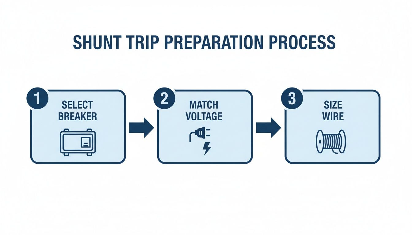
Nailing this sequence—matching the breaker, coil voltage, and wire gauge—is the first step to avoiding some of the most common headaches during installation.
Wiring the Classic Emergency Stop (E-Stop) Circuit
The E-Stop button is the bread and butter of shunt trip applications. It’s the big red button that gives anyone a way to kill power to a machine from a safe distance, a non-negotiable safety feature on pretty much any industrial equipment.
You only need a few parts for this job:
- A solid control power source (a 120V AC control transformer is a common choice).
- A fuse or small breaker to protect that control circuit.
- The E-Stop button itself, which needs at least one normally open (N.O.) contact.
- And of course, the shunt trip breaker.
The wiring couldn't be more straightforward. Your control power "hot" leg runs through the fuse, then heads to one side of the E-Stop's normally open contact. The other side of that contact wires directly to one of the shunt trip coil terminals (usually marked S1 or C1). To finish it off, the second coil terminal (S2 or C2) ties back to the neutral or common side of your control power.
When everything is normal, that N.O. contact is open, so the coil sees no voltage. The second someone hits that E-Stop, the contact slams shut, energizing the coil and tripping the breaker instantly.
Field Tip: Don't skimp here. Always use a proper, clearly labeled E-Stop button—the big, red, mushroom-head style. You want it to be unmistakable in a crisis. Using a normally open contact is also critical; it ensures the coil is only powered for a split second, preventing it from overheating and burning out.
Hooking Up a PLC-Controlled Shunt Trip
In automated factories, the signal to trip often comes from a Programmable Logic Controller (PLC). This lets the system automatically shut down equipment based on things like sensor faults, over-temperature alarms, or safety interlocks. The wiring is nearly identical to the E-Stop, but you're swapping the manual button for a PLC output relay.
The power flow is the same. Start with your fused control power, which feeds the "common" terminal on a PLC relay output. The normally open (N.O.) terminal from that same relay output then runs over to one of the shunt trip coil terminals. Just like before, the other coil terminal connects back to your control power neutral or common.
When the PLC's programming logic calls for a shutdown, it energizes that output relay. The contact closes, sends the juice to the shunt trip coil, and the main breaker opens. This is a go-to setup for everything from tripping a large motor during a fault to shutting down a conveyor line when a safety gate is opened.
Critical Wiring and Grounding Habits
No matter what's triggering the trip, a few practices are non-negotiable. These are the small details that mark the difference between a pro install and a future service call.
- Label Every Wire: Seriously. Label every control wire at both ends, saying where it came from and where it's going. It turns a future troubleshooting nightmare into a simple, logical process.
- Watch DC Polarity: If you're working with a DC coil (like 24V DC), mind the polarity. The terminals will almost always be marked with a (+) and (-). Reversing them can easily fry the coil.
- Ground Everything: The breaker's metal enclosure and any other metallic parts need a solid connection to the equipment ground. This is basic electrical safety 101 to prevent shock if there's ever a fault.
- Torque It Down: Use a torque screwdriver and tighten every terminal to the manufacturer's spec. A loose control wire is a recipe for an intermittent problem, which is one of the toughest things to track down in the field.
Wiring a shunt trip breaker is about more than just connecting the dots. You're building a safety circuit that has to work, without fail, when it matters most. By following these practical steps and field-tested tips, you can be confident your installation will be right, and more importantly, reliable.
Testing and Maintaining Your Shunt Trip System
Getting the wiring diagram for a shunt trip circuit breaker right is a great start, but it's just that—a start. Real-world reliability comes from putting the system through its paces with rigorous testing and then sticking to a consistent maintenance schedule.
This is the commissioning phase, where you prove the system will snap into action the second it's needed in an emergency. Without this final check, you're not engineering a safety system; you're just hoping it works.
The goal is simple: make sure that hitting your remote E-stop or triggering a signal instantly opens the circuit breaker. This isn't just a "nice to have." It’s a critical safety function that demands documented proof it works before you ever turn the system over for live operation.
Commissioning Your Shunt Trip Circuit
Before you flip any switches, a few last-minute visual checks are in order. Grab your torque wrench and make sure every terminal screw is tightened to the manufacturer's spec. A loose control wire is one of the most common reasons a brand-new installation fails its first test. Double-check that your wire labels match the diagram and that the control circuit fuse is the right size and properly seated.
Once everything looks good, the test itself is straightforward, but you have to be methodical.
- Check Your Control Voltage: First things first, keep the main breaker OFF and energize only the control circuit. Get your multimeter out and verify you have the correct voltage—whether it's 120V AC or 24V DC—at the line side of your E-stop button or other initiating device. This quick check tells you the control power source is healthy and ready to go.
- Test the Trip: With the area clear and all safety protocols followed, turn the main circuit breaker ON. Now, hit the initiating device. Press the E-stop or trigger the PLC output. You should hear a solid, satisfying "clack" as the breaker trips open.
- Confirm De-energization: After the breaker trips, use your multimeter again to confirm zero voltage on the load side of the breaker. This is the crucial step that proves the main contacts have fully opened and the downstream equipment is truly isolated.
- Reset and Repeat: Finally, reset the E-stop button or clear the PLC signal, and then reset the circuit breaker itself. It should reset cleanly without tripping again. If it re-trips immediately, you might be dealing with a stuck contact in your E-stop or a latched PLC output that needs a closer look.
The Importance of Long-Term Maintenance
A shunt trip system isn't something you can just "set and forget." Over time, plant vibrations can loosen terminals, dust and grime can gum up mechanical parts, and coils can eventually fail. The only way to ensure it works five years from now is to implement a regular, documented maintenance plan.
Industry data on circuit breaker failures tells a powerful story. Analyses from 1980–2000 found that failures in mechanical and auxiliary trip assemblies (including shunt trips) were behind roughly 24-26% of common-cause failures. The primary culprit? Inadequate maintenance. The data also shows that routine functional testing can reduce the odds of a trip failure during an emergency by an estimated 30–60%. You can get the full story from this in-depth reliability study.
For any plant engineer or maintenance manager, that data is a clear call to action. A preventive maintenance schedule isn't optional; it's essential.
A Practical Maintenance Checklist
A simple checklist helps keep your technicians consistent and ensures nothing gets missed. For most industrial environments, running through these checks every 6 to 12 months is a solid best practice.
- Visual Inspection: Look for the classic signs of overheating, like discolored plastic on terminals or browned wire insulation. Check for any buildup of dust or debris around the breaker and its mechanism that could interfere with its operation.
- Terminal Tightness: With the system fully de-energized and locked out, put a torque wrench on every control and power terminal. Loose connections are a top cause of intermittent problems and outright failures.
- Functional Test: This is the big one. Run the exact same commissioning test you did on day one. Activate the trip device and confirm the breaker opens instantly. It’s the only way to know for sure that the coil and mechanism are still in good working order.
- Documentation: Log everything. Write down the date, the technician’s name, and the pass/fail result of the functional test. This logbook is gold during a safety audit and is critical for tracking the health of your safety systems over their entire lifecycle.
This disciplined approach to testing and maintenance is what turns a well-wired diagram into a dependable safety system you can truly count on.
Troubleshooting Common Shunt Trip Wiring Problems
Even when you’ve followed a wiring diagram to the letter, things go sideways in the field. When a brand-new safety circuit fails its first test, the pressure is on to find the glitch—and fast.
Let's walk through the most common headaches I've seen and how to diagnose the root cause with a bit of logic. A systematic approach is your best friend here. Instead of just poking around, we’ll tackle these issues based on what you’re seeing, which isolates the variables and gets you to the solution much more quickly.
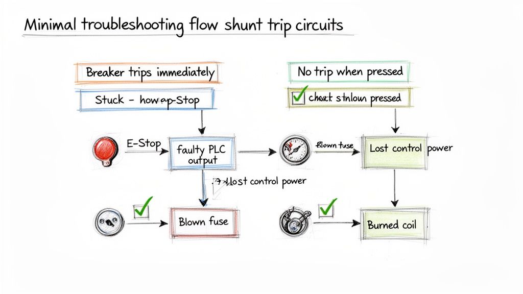
Symptom One: The Breaker Trips Immediately on Reset
This is a classic. You go to close the breaker handle, and click—it immediately snaps back open. This almost always points to an active trip signal. The shunt coil is getting power the instant you try to reset the breaker.
The cause is rarely the breaker itself. More often than not, the initiating device is stuck in the "closed" or "tripped" position, continuously sending voltage right to the coil.
Here’s where to start your investigation:
- Check the E-Stop Button: Is a mushroom-head E-stop actually pulled out to its reset position? I can't count how many times I've seen a button still latched in from a previous test or bump.
- Inspect PLC Outputs: If a PLC is running the show, you need to look at the logic and the status of the output relay. A sticky relay or a simple programming error could be holding that contact closed.
- Look for Shorted Wires: It’s less common, but the control wires going to the shunt coil could be shorted together somewhere. This effectively bypasses the initiating device and sends constant power straight to the coil.
Troubleshooting Takeaway: An immediate re-trip means your control circuit is "live." The problem isn't the breaker failing; it's the trip signal never turning off. Focus your energy on whatever is sending that signal.
Symptom Two: The Trip Button Does Nothing
The complete opposite problem is just as common: you slam the E-stop button, and… nothing. The breaker stays closed, and the equipment keeps humming along. This tells you there's a break somewhere in your control circuit, preventing voltage from ever reaching that shunt coil.
When you hit this wall, think of it as tracing a path of electricity and finding where it dead-ends.
A Logical Diagnostic Path:
- Verify Control Power: Is the control circuit even on? Grab your multimeter and confirm you have the proper voltage (e.g., 120V AC or 24V DC) at the source. It’s a dead-simple first step that often ends the search right there.
- Check the Control Fuse: This is the number one culprit, hands down. A blown fuse in the control circuit will kill power to the entire trip system. Always keep spares in your bag.
- Test the Initiating Device: With the power off, switch your meter to continuity and test the E-stop or relay contact. Does it show a closed circuit when you press the button? Contacts wear out and fail. It happens.
- Inspect the Shunt Coil: If you confirm power is reaching the coil terminals when the button is pressed but the breaker isn't tripping, the coil itself is likely toast. You can test its resistance (with power off, of course) and check it against the manufacturer’s spec sheet.
Sometimes, a little context helps. While a shunt trip is an intentional action, understanding the common reasons why a circuit breaker keeps tripping from overloads or short circuits can help you distinguish a control problem from a power problem. For a deeper look into those issues, our guide on https://eandisales.com/uncategorized/what-can-cause-a-breaker-to-trip/ is a great resource.
Common Questions About Wiring a Shunt Trip Breaker
Even with a perfect diagram, wiring up a shunt trip breaker for the first time can bring up a few questions. Let's walk through some of the most common sticking points I see in the field to make sure your installation is safe and works the first time.
Can a Shunt Trip Coil Stay Energized?
Absolutely not. If you remember only one thing, make it this: a shunt trip coil is built for momentary duty only. Think of it like the starter in your car—it just needs a quick jolt of voltage to do its job.
Leaving constant power on the coil is a surefire way to burn it out, and it happens fast. We're talking a matter of minutes. That's why your control device, whether it's an E-stop button or a relay, must use a normally open (N.O.) contact that only closes for the brief moment you need to trip the breaker.
What Happens If I Use the Wrong Voltage on the Coil?
Using the wrong voltage is a recipe for failure, simple as that. The results are predictable, and neither is good.
- Under-voltage: If you send 24V DC to a 120V AC coil, for example, you won't get enough magnetic force to trip the breaker. The coil just won't have the muscle to work the internal mechanism. Your safety circuit will be completely useless.
- Over-voltage: This is even more dramatic. Hooking up 120V AC to a 24V DC coil will cause it to instantly overheat and fry itself. You'll get a puff of smoke, a dead coil, and maybe even a damaged breaker.
Before you land a single wire, double-check the voltage rating printed right on the shunt trip accessory against your control circuit's power source. It's a five-second check that prevents a costly headache.
Is a Separate Fuse for the Shunt Trip Circuit Necessary?
Yes, and it's not optional. The control circuit for the shunt trip needs its own dedicated overcurrent protection, usually a small fuse or a miniature circuit breaker. This little fuse is there to protect the control wiring and the coil itself if a short circuit ever happens.
Without that fuse, a fault in your control wiring could become a fire hazard or take down your entire control power supply. Sizing is crucial here. You need a fuse rated to handle the coil's quick inrush of current without popping, but small enough to blow instantly on a real fault. Check the manufacturer's spec sheet, but you're typically looking for something between 0.5A and 2A.
Can I Add a Shunt Trip to Any Circuit Breaker?
Nope. Shunt trip accessories aren't a universal, one-size-fits-all part. The circuit breaker itself has to be designed from the factory to accept a shunt trip module. These specific breakers have the necessary internal linkages and mounting slots for the accessory to physically connect and operate.
Trying to force a shunt trip into a standard breaker that wasn't made for it is just not going to work and is completely unsafe. Always confirm your breaker's model number can take a shunt trip by checking its technical documents before you buy anything.
Thankfully, finding compatible components is getting easier. The global market for these accessories was around USD 1.1 billion in 2024 and is expected to double by 2033, thanks to a huge push for better industrial safety and automation. This growth means better availability and clearer documentation from manufacturers. You can dig into this market trend over on Verified Market Reports.
What Is the Difference Between a Shunt Trip and an Undervoltage Release?
I hear this one all the time. It's easy to get them mixed up, but they do the exact opposite job.
- Shunt Trip (ST): This trips the breaker when you apply voltage to it. Think of it as an active, "trip on command" device. It's what you need for E-stops and remote shutdowns.
- Undervoltage Release (UVR): This trips the breaker when voltage is lost or dips too low. It needs constant power to hold the breaker closed. This is used to prevent equipment from unexpectedly restarting after a power failure.
Choosing the right one is all about the safety function you're trying to achieve. If it's an emergency stop, you always want a shunt trip.
At E & I Sales, we specialize in providing correctly specified UL-listed control solutions, including pre-wired and tested shunt trip circuits that eliminate guesswork and ensure your systems meet the highest safety standards. For expert guidance on your next project, visit us at https://eandisales.com.