
Before you even think about stripping a wire, grabbing your schematic is the most important thing you'll do. A wiring diagram for lighting contactors is your roadmap, and it clearly separates the high-voltage power side from the low-voltage control side. Getting this right isn't just good practice—it's what keeps the system safe and makes troubleshooting a breeze later on.
Reading and Understanding Your Wiring Diagram
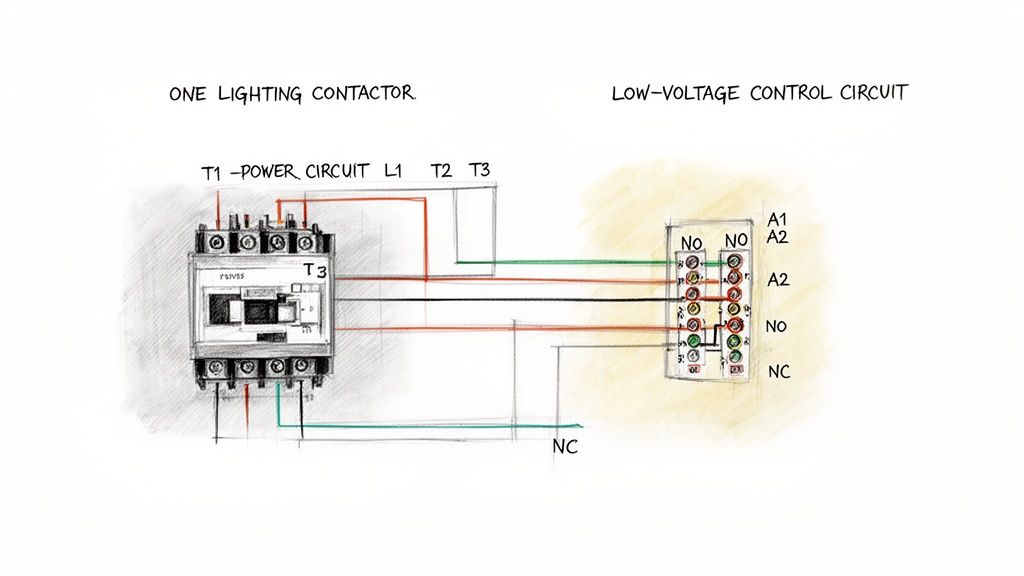
Think of the wiring diagram as the blueprint for your whole lighting setup. It’s a visual guide to the two different jobs happening inside that contactor: the power circuit, which handles the heavy lifting, and the control circuit, which is the brains of the operation.
It's a classic rookie mistake to mix these two up, and that can lead to fried components or, worse, a dangerous situation. Learning to read this map correctly from the start means you can walk up to any standard schematic and know exactly how to turn it into a real-world, working installation.
Identifying Key Terminals and Symbols
First thing's first, let's get familiar with the key players you'll see on almost any diagram. Every schematic will label these main connection points.
- Power Terminals (L1, L2, L3): This is where your high-voltage power comes in from the breaker panel.
- Load Terminals (T1, T2, T3): This is the "out" side, where power heads off to the light fixtures.
- Coil Connections (A1, A2): Here's the heart of the control circuit. When the right low voltage hits these terminals, the electromagnet pulls in, and the main contacts close.
- Auxiliary Contacts (NO/NC): These are small, low-power contacts. They aren't for the main lights; instead, they're used for things like sending a status signal to a control panel or preventing another piece of equipment from turning on.
The absolute most critical concept to grasp is the separation between power (L1-L3 to T1-T3) and control (A1-A2). This is what allows a tiny, safe signal—like from a 24V timer—to safely command a powerful 480V circuit without the two ever crossing paths.
Decoding Power and Control Paths
On the diagram, you'll notice the power circuit is usually drawn with thicker lines. This represents the beefier wire needed to handle the current your lights will draw. The path is dead simple: power comes in at L1, L2, and L3, waits at the open contacts, and then flows out through T1, T2, and T3 as soon as the contactor pulls in. The basic principle is very similar to what you’d see in other heavy-duty applications; you can see more examples in our guide to the three-phase motor wiring diagram.
The control circuit, on the other hand, is shown with thinner lines. This is the path that connects your switch, timer, or occupancy sensor to the A1 and A2 coil terminals. Its only job is to tell the contactor when to energize.
When you look at the specs, it’s clear these devices are built to last. A typical lighting contactor is rated for 1 million mechanical operations and can handle 100,000 electrical cycles at its full rated load. The diagram is what shows you how to properly isolate those heavy-duty power circuits from the delicate control logic, ensuring a long and reliable service life.
Time to get our hands dirty with the high-voltage side of things. This is where the real power—the juice that actually runs your lights—gets hooked up to the contactor. We're aiming for clean, secure connections that will safely carry the load for the long haul.
But before you even think about touching a wire, let’s talk about the single most important step: Lockout/Tagout (LOTO). Seriously. Kill the power at the breaker, slap your lock and tag on it, and then double-check with your multimeter to make sure it's truly dead. This isn't optional; it's what separates professionals from amateurs and keeps you safe.
Connecting Three-Phase Power
In most commercial or industrial spaces, you'll be dealing with three-phase power. It’s the standard for balancing heavy electrical loads across a facility. Looking at your contactor, you’ll see the power terminals clearly marked.
- Supply Side: Your incoming power conductors (often black, red, and blue) will land on the terminals marked L1, L2, and L3.
- Load Side: The wires heading out to your light fixtures connect to the corresponding terminals labeled T1, T2, and T3.
It's a simple, direct path. Power comes in on the "L" side, waits for the coil to pull the contacts closed, and then flows out the "T" side to the load.
One of the biggest mistakes I see in the field is undersized wire. It’s a ticking time bomb. Wires that are too small for the amperage they're carrying will overheat and can easily start a fire. If you're ever in doubt, use a good set of electrical calculation tools to confirm the right wire gauge for your specific load and distance. Don't guess.
Handling Single-Phase Connections
What if you're working in a smaller area or on a system that uses single-phase power? No problem. The concept is identical, just with fewer wires to manage.
You’ll have a single hot (line) wire and a neutral. You'll just use two of the contactor's poles. A common way to do this is to land the incoming hot on L1 and the neutral on L2. The outgoing hot wire to your lights then connects to T1, and the outgoing neutral connects to T2. Simple as that.
A Pro Tip on Terminations: Get yourself a calibrated torque screwdriver. It’s a game-changer. Over-tightening a terminal lug can be just as bad as leaving it too loose—you can damage the equipment or create a high-resistance hot spot. Check the manufacturer’s spec sheet for the proper torque values and hit them every time.
To help visualize the key differences, here's a quick breakdown of what to keep in mind for each system.
Power Wiring Quick Reference for Lighting Contactors
| Parameter | Single-Phase System | Three-Phase System |
|---|---|---|
| Incoming Wires | Typically one hot (line) and one neutral. | Three hot conductors (e.g., L1, L2, L3). |
| Contactor Poles Used | Usually two poles are sufficient (one for hot, one for neutral). | Requires a contactor with at least three poles. |
| Voltage | Common voltages are 120V or 277V. | Common voltages include 208V, 240V, or 480V. |
| Load Balancing | Not a primary concern as it's a single circuit. | Critical for distributing the lighting load evenly across the building's electrical service. |
| Typical Use Case | Smaller commercial spaces, residential applications, or specific zones. | Industrial facilities, large commercial buildings, and high-power lighting arrays. |
Ultimately, whether you're wiring a simple single-phase circuit or a complex three-phase system, the fundamentals of good workmanship apply.
And remember, your PPE is non-negotiable. At the very least, have your safety glasses and properly rated gloves on. Taking a few extra moments to be methodical and safe is what turns a potentially dangerous job into just another professional installation.
Designing and Wiring Your Control Circuit
Alright, this is where the magic happens. The power wiring is the muscle, but the control circuit is the brain of the whole operation. This is what turns a simple box of parts into a smart switching system that knows exactly when to turn those high-power lights on and off.
Getting this part right is what separates a reliable, automated lighting setup from one that's a constant headache. We're moving past a basic light switch on the wall and into the real-world control schemes you'll actually find on the job. The entire goal is to send a signal to the contactor's coil—you'll see it marked A1 and A2—at just the right moment.
From Simple Switches to Smarter Setups
The most basic setup you can have is a simple maintained switch. Flip it one way, power flows to the coil (A1), the contactor pulls in, and the lights come on. Flip it the other way, power is cut, and everything goes dark. Simple.
But in any modern industrial or commercial space, you need more than that. Let’s look at some of the most common and practical upgrades I've wired in over the years:
- Timers for Scheduled Lighting: This is a classic. You wire an industrial timer into the control circuit to handle lighting for specific shifts or business hours. The timer's contacts act as the switch, automatically energizing the contactor coil based on whatever schedule you program.
- Photoelectric Sensors for Dusk-to-Dawn Control: For any outdoor or perimeter lighting, a photocell is your best friend. Instead of a switch, you wire the sensor's output to the A1 terminal. When the sun goes down, the photocell sends the signal. When the sun comes up, it cuts it. It's set-it-and-forget-it control.
- Pilot Lights for Status Indication: How do you know if the lights 500 feet away are actually on? You add a normally open (NO) auxiliary contact to the side of your contactor. When the main contactor pulls in, this little auxiliary contact closes, sending power to a small indicator light on your panel door. It's a quick, at-a-glance confirmation that the system is working.
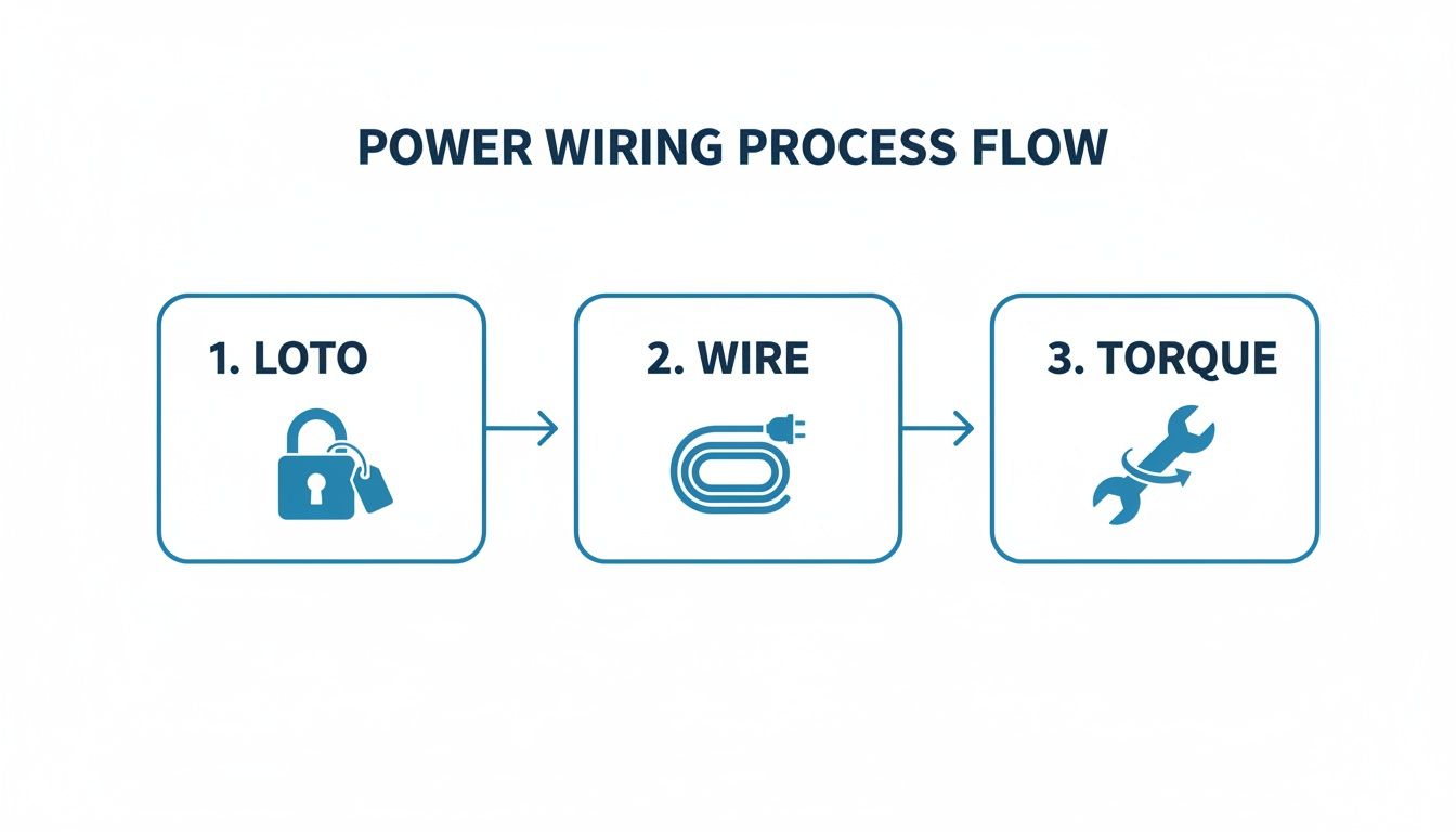
This workflow isn't just a suggestion; it's the professional standard. Safely isolating power, making clean connections, and torquing everything down is non-negotiable.
Matching the Coil Voltage Is Non-Negotiable
Here’s a detail that trips up a surprising number of people: selecting the right coil voltage. This has absolutely nothing to do with the big 480V or 208V power running through the main contacts (L1/T1, etc.). You have to match the coil to your control power source.
A mismatched coil is a recipe for instant failure. If you send 120VAC to a 24VDC coil, you'll hear a pop and smell smoke—it’s toast. Send 24VDC to a 120VAC coil, and you'll get… nothing. Always, always double-check the voltage printed right on the contactor's coil itself.
You’ll typically run into a few common coil voltages:
- 120VAC: Very common. It's usually pulled from a small control transformer inside the panel.
- 24VAC/DC: The go-to standard for PLCs and most modern automation controls.
- 277VAC: You'll see this when the control power is tapped directly from one leg of a 480/277V lighting circuit.
Lighting contactors are the unsung heroes in big facilities like warehouses, retail stores, and office buildings. In these applications, latching-type contactors are becoming incredibly popular because they can slash coil power consumption by up to 95%. They only need a quick electrical pulse to switch on or off, making them ideal for energy-conscious designs.
Figuring out these control schemes is a fundamental skill. For a much broader look at how this fits into the bigger picture, check out our guide on industrial control panel design. This is where your wiring diagram for lighting contactors becomes a critical piece of a much larger, more sophisticated automation strategy.
Going Beyond the Basics: Safety and Advanced Control
A truly professional installation does more than just switch the lights on and off. It's about building in layers of safety and intelligent control. This means getting serious about protecting both the high-voltage power circuit and the more delicate control circuit. Before you can even think about advanced logic, you have to get the protection right.
That starts with properly sized fuses or circuit breakers. You need separate protection for the main power lines feeding the lights and for the low-voltage control wiring. A short in a simple toggle switch shouldn't ever be able to take down an entire lighting panel, and a small, dedicated fuse on the control side is what prevents that from happening.
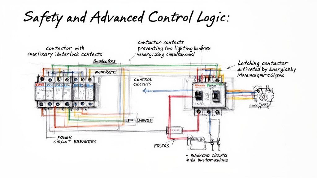
Creating Hardwired Safety Interlocks
Once your circuits are properly protected, you can start using the contactor itself to add some smarts. Those little auxiliary contacts—the NO (Normally Open) and NC (Normally Closed) terminals—are your best friends for creating bulletproof safety interlocks.
Let's say you have two banks of high-bay lights that should absolutely never be on at the same time. Easy. You wire the control signal for the second contactor through an NC auxiliary contact on the first one. This creates a simple, physically enforced logic: if Contactor #1 is energized, its NC contact opens up, cutting off the path for the signal to ever reach Contactor #2.
This kind of hardwired interlock is infinitely more reliable than relying on a PLC or smart relay programming alone. It’s a fundamental concept in machine safety for a reason—it just works.
A critical part of any safety design is accounting for all potential failure modes. This includes ensuring your system is resilient against electrical faults. For a deeper understanding of this topic, you can find valuable information in our detailed guide on ground fault protection.
Wiring Latching Contactors for Big Energy Savings
For large facilities where the electric bill is a constant concern, the latching contactor is a total game-changer. You might also hear it called a mechanically held contactor. Unlike a standard contactor that needs constant power flowing through its coil to stay closed, a latching contactor works differently.
It has two separate coils: one to "latch" (close the main contacts) and another to "unlatch" (pop them open). The beauty is that each coil only needs a quick, momentary pulse of power to do its job.
- To turn lights ON: You hit the "LATCH" coil with a brief signal. A mechanism inside the contactor closes the contacts and physically locks them into place. The coil can then de-energize completely.
- To turn lights OFF: You send another momentary signal, this time to the "UNLATCH" coil, which releases the mechanical lock.
This design slashes energy consumption because there's no continuous current draw. As a bonus, it also gets rid of that annoying hum you often hear from standard AC contactors.
When you're designing any control circuit, especially for critical systems, it pays to think through every angle of safety and reliability. For example, reviewing the fire safety guidelines for emergency lighting shows how specialized systems build in their own unique protections. The core principles are the same, though, making your wiring diagram for lighting contactors the single most important document for proving the system is built right.
Commissioning Your System Like a Professional
Just because you've landed the last wire doesn't mean the job is done. The final, critical step is commissioning—this is what separates a truly professional installation from one that’s just functional. It’s where you meticulously verify every single connection and function before a single watt of load power flows through it.
Think of it as a pre-flight checklist for your electrical system. Skipping this part is just asking for trouble, whether it's immediate equipment failure, a frustrating callback, or a dangerous fault. A few extra minutes of methodical checking here will save you hours of headaches later.
The Essential Pre-Power Checklist
With the main breaker locked out and tagged, it's time to go point-to-point. This isn't just a quick once-over; it's a systematic hunt for any mistakes made during the install.
- Continuity Checks: Get your multimeter out and put it on the continuity setting. Does your switch actually complete the circuit to the A1 terminal? Do you have a solid, unbroken path from the T1 terminal all the way to that first light fixture? Ring out every single wire.
- Torque Verification: Grab your calibrated torque screwdriver. Go back and check every single terminal—power and control. I can't tell you how many failures I've seen traced back to a loose connection that created a hot spot.
- Control Device Function: Manually activate everything. Push the override button, put your hand over the photocell, and spin the dial on the timer. Make sure each physical action does exactly what it's supposed to do at the control terminals.
The real mark of a pro is in the details. Clean, organized wireways don't just look good—they improve airflow and make future troubleshooting a whole lot safer and easier for the next person in that panel. Tidy wiring is a sign of true craftsmanship.
Final Touches and Documentation
After you've confirmed the wiring is rock solid, it's time for the final piece: labeling. Every control wire needs a clear, unique identifier on both ends. It might seem tedious, but it transforms future maintenance from a guessing game into a straightforward task.
Lighting contactors have been the backbone of industrial control for decades, and they've evolved right along with the technology. Older workhorse models, like ABB's CR463L series, were incredibly versatile, offering up to 74 different circuit combinations and handling anything from 120V to 600V AC.
This history, carried on by trusted distributors like E & I Sales since 1974, is built on the importance of getting the wiring exactly right. The diagrams for those classic units even included clever safety indicators, like a button that physically protruded when the contacts were closed. It’s a great reminder of how valuable clear, physical verification is—a principle that's just as crucial today. You can learn more about these advanced contactor specifications to see how the technology has grown.
Common Questions We Hear in the Field
Even with the best wiring diagram taped to the panel door, some questions always seem to come up on the job. Let’s walk through a few of the most common ones I hear from technicians to clear up the confusion and help you sidestep those little issues that can turn into big headaches.
Getting these details right is what separates an installation that just "works" from one that's dead reliable for years to come. It’s about knowing the why behind the wiring.
Lighting Contactor vs. Motor Contactor
So, what’s the real difference between a lighting contactor and a motor contactor? They look practically the same, but they're built for completely different battles.
Lighting contactors are specifically beefed up to handle the massive inrush current you get when you energize a huge bank of fluorescent or LED lights. That initial surge can be absolutely brutal—many, many times the normal running current. A motor contactor, on the other hand, is designed to handle the sustained inductive loads from a motor.
You'll notice lighting contactors are rated in amps, with no horsepower (HP) rating in sight. If you try to use a standard motor contactor for a big lighting load, you're asking for trouble. Sooner or later, those repeated inrush spikes will weld the contacts shut.
Why Is My Contactor Buzzing So Loud?
A loud, angry hum or buzz from a contactor is its way of screaming for help. Don't ignore it. Nine times out of ten, the problem is with the coil or the magnetic core that pulls the contacts closed.
Here are the usual suspects:
- Low Control Voltage: The coil isn't getting enough juice to pull the magnet in tightly.
- Junk in the Magnet: A tiny bit of dust, metal shaving, or grime is stuck between the faces of the magnet.
- Broken Shading Ring: On an AC contactor, this little copper ring is critical for preventing chatter. If it cracks or breaks, the buzzing starts.
First thing's first: grab your meter and check the control voltage right at the coil terminals. If that's good, lock out the circuit, and give the magnet faces a careful inspection and cleaning. A chattering buzz is often the last gasp of a dying contactor.
One of the most common service calls is for a buzzing contactor. Before you even think about ordering a replacement, kill the power, lock it out, and just wipe down the magnetic surfaces with a clean, dry rag. More than half the time, that's all it takes. It's a five-minute fix that can save you a ton of hassle.
Can You Mix and Match Power and Control Voltages?
"Can I control a three-phase contactor with single-phase power?" Absolutely. In fact, this is how it's done in almost every industrial plant you'll ever walk into.
The power circuit (the high-voltage side switching the load) and the control circuit (the low-voltage side with the coil) are two totally separate things. They're electrically isolated from each other inside the contactor.
The voltage on the coil has nothing to do with the voltage on the load. You can easily have a contactor switching a 480V three-phase lighting circuit that's being controlled by a 120VAC signal from a timer, or even a 24VDC signal from a PLC. The key is just to order a contactor with a coil that matches your control voltage.
At E & I Sales, we live and breathe this stuff. We provide the heavy-duty components and practical advice you need for complex industrial jobs. From motor controls to custom UL-listed panels, we help you build systems that are safe, bulletproof, and efficient. See how our experience can back up your next project at https://eandisales.com.