
Quick Shunt Trip Wiring Overview
Selecting the right coil voltage and matching it to your control circuit can shave hours off panel build time. Below, you’ll find voltage ratings, AC vs. DC options, and essential safety checks in a single glance.
Shunt trip coils range from 12 VDC all the way up to 525 VAC, fitting everything from PLC outputs to heavy industrial emergency stops. (Learn more about shunt-trip coils on literature.rockwellautomation.com)
This simple addition to a molded-case breaker lets you trigger a trip remotely with an external voltage. Get your coil right, and you’ve already solved half the puzzle.
Common Shunt Coil Voltages And Applications
Before you grab your wire cutters, double-check that the coil voltage matches your control supply. Use the table below to see which voltages and applications pair together most often.
| Coil Voltage | Control Voltage Type | Typical Use |
|---|---|---|
| 12 VDC | DC | PLC Outputs |
| 24 VDC | DC | Safety Relays |
| 120 VAC | AC | Motor Shunt Trips |
| 240 VAC | AC | Emergency Stops |
Keep this chart handy to avoid last-minute surprises in the field.
Safety Checks And Upstream Protection
Never power a shunt-trip coil without its own control fuse. A small fuse per NEC 240.4 plus correctly sized conductors prevent coil burnout—and eliminate annoying nuisance trips.
Protect the control circuit according to local code to keep the system both safe and reliable.
- For AC coils (120 VAC or 240 VAC), tie into a local relay or a PLC output
- For DC coils (24 VDC or 48 VDC), add a flyback diode and size your fuse to handle inrush
Example Control Panel Scenario
Picture a packaging line emergency-stop loop driven by a 24 VDC shunt trip. A PLC SINK output energizes the coil through a 1 A fuse, while a flyback diode tames voltage spikes.
You’ll need:
- A PLC output rated for your coil’s inrush and steady-state current
- A control transformer sized for coil pickup
- A thermal-magnetic fuse or mini-breaker per OEM guidelines
Clear routing, consistent wire colors, and these upfront checks cut wiring errors—and slash commissioning time.
This overview sets the stage for detailed schematics and advanced configurations. Next, we’ll dig into coil inrush vs. steady currents so you can size fuses and transformers with confidence.
Understanding Shunt Trip Components
Inside a control panel, remote shutdown hinges on two paired parts: the molded-case breaker and its shunt-trip coil. The breaker carries the main load, snaps into a UL-approved footprint, and needs the correct amperage rating to handle both the line and any accessory trip unit.
The shunt-trip coil clips onto the breaker side, offering two control-voltage terminals and a spring-release mechanism that pops the breaker open in an instant.
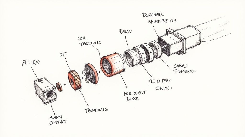
Most setups rely on a small relay or a PLC output to energize that coil. For cleaner wiring and less interference, I usually mount these components right by the door hinge—shorter runs, quieter operation, and faster troubleshooting.
“A tidy panel makes troubleshooting much faster,” notes a veteran packager who’s wrestled with cramped cabinets.
Key Safety Integrations
When an emergency hits, shunt-trip breakers link directly into life-safety systems. Fire-alarm panels, gas-detection interlocks, and e-stop loops all send a signal to the coil, instantly cutting power.
- Fire alarm tie-ins on non-life-safety loads
- Gas detection shutdowns in processing lines
- Emergency-stop loops on automated packaging equipment
For deeper reading, see Wikipedia. Getting conductor sizes right and picking the proper breaker ensures you meet both NEC and UL standards.
Terminal Connections And Wiring Paths
You’ll find the coil lugs right beside the line and load terminals on the breaker frame—mark them clearly in your wiring diagram. A simple color-code and neat labels will speed up commissioning and prevent miswires.
- Map out the common and normally-open coil terminals
- Route control wires back to your relay or PLC output
- Protect the coil with a fuse sized for its inrush and steady-state current
| Device | Control Voltage | Coil Current |
|---|---|---|
| Relay | 24 VDC | 150 mA |
| PLC | 120 VAC | 80 mA |
I always bundle coil conductors separately from the power feeders to cut down on electromagnetic interference.
Check out our ABB molded-case breaker guide for panel integration.
Always test coil activation under nominal voltage before applying power to the main circuit.
Best Practices You Need To Know
- Match coil voltage exactly to eliminate extra transformers or relays
- Tag both coil leads with ID labels at each termination
- Position the control fuse within 12 inches of the breaker per NEC 240.4
With these checks in place, wiring a shunt-trip breaker goes from guesswork to routine. Next up, we’ll dig into inrush currents and transformer sizing so your fuse choices stay rock-solid. Remember to document every connection in your panel drawings and keep your schematics updated with clear revision dates.
Happy wiring always!
Designing Reliable Control Circuits
Nothing’s more frustrating than a control circuit that trips when it shouldn’t—yet refuses to trip when it must. Delivering the right coil voltage under both inrush and steady‐state conditions sets the stage for rock‐solid performance. Overlook transformer sizing or fuse selection, and you’ll wrestle with brownouts or no-trip failures.
OEM datasheets usually save you the legwork, listing coil voltages, torque specs and protective fuse recommendations side by side. Lean on that data early in your design.
Control Circuit Essentials
Matching coil voltage, fuse rating and conductor ampacity may sound obvious, but it’s the detail work that separates a reliable panel from a headache.
- Pick the coil voltage exactly as shown in vendor diagrams—24 VDC or 120 VAC, no guessing.
- Choose a fuse that handles the coil’s inrush current plus a safety margin, per UL guidelines.
- Size your wiring using NEC conductor ampacity tables to avoid overheated runs or voltage drop.
In practice, separating control cables from power wiring cuts down on EMI. And remember: placing the fuse within 12 inches of the coil terminal is more than a suggestion—it’s a best practice.
As a rule of thumb, a 24 VDC coil drawing 150 mA steady current won’t work on anything smaller than AWG 22 without risking hotspots.
Coil Voltage And Protection Comparison
Before you grab a fuse drawer at random, use the table below to lock in the right combination of coil voltage, fuse size and inrush current.
| Voltage | Recommended Fuse | Typical Inrush Current |
|---|---|---|
| 24 VDC | 1 A slow-blow | 150 mA |
| 120 VAC | 0.5 A fast-acting | 80 mA |
| 525 VAC | 0.2 A standard fuse | 50 mA |
Keep this chart handy during design reviews and panel builds—it’s saved me from more than one nuisance trip.
Avoiding Nuisance Trips
Transient spikes on your control supply are the usual suspects behind unexpected trips. Tackling them up front means fewer service calls.
Snubber and surge suppression guidelines:
- Flyback diodes across DC coils slash voltage spikes and extend coil life.
- RC snubbers tame AC coil transients when panel space allows.
- Line chokes or surge arrestors add an extra layer of noise suppression.
A quick field retrofit I handled once used spare terminals for added surge modules—and that change stopped weekly false trips.
Always follow OEM coil torque specs to prevent loose connections and false trips.
Market reports even peg the shunt-trip market near US$866 million in 2024. For deeper specs on coil behavior and protection, check out Discover detailed specs.
Commissioning And Documentation
Great wiring diagrams aren’t just nice to have—they’re your defense when audits roll around.
- Record coil voltage, fuse size and conductor gauge right on your schematic.
- Note torque values, revision dates and who signed off on changes.
- Before applying power, verify coil polarity, tighten connections and confirm fuse placement.
- Perform a controlled trip test to check for panel surges.
You might also find extra tips on optimized layouts in our article Industrial Control Panel Design
Testing Under Fault Conditions
Simulating overloads and voltage sags uncovers weaknesses early.
- Measure coil current with a clamp meter at the rated pull-in voltage, aiming for ±5%.
- Test fuse blow-times under real inrush scenarios to verify protective behavior.
- Use thermographic scans after multiple trips to spot hot junctions.
Updating your diagrams with test results and scan images ensures no surprises when the line goes live—and makes inspections a breeze.
Real-World Wiring Schematics
When you’re laying out a control panel, nothing beats clear, proven schematics. We’ve gathered five shunt-trip breaker arrangements that cover motor starters, MCC integrations, emergency stops, PLC-triggered trips and transfer-switch interlocks. Each setup includes parts lists, voltage callouts and cabinet-sizing advice.
These diagrams aren’t just theoretical. They zero in on real-world challenges—EMI mitigation, NEC compliance, color-coding tips that shave hours off commissioning. Use them as a launching point and adapt to your plant’s quirks.
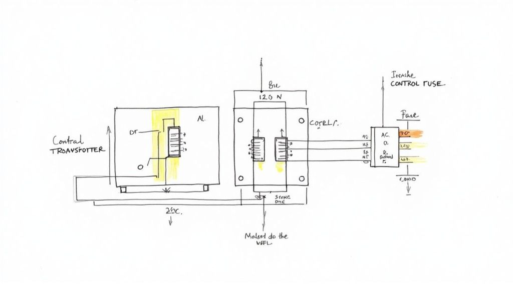
Motor Starter Shunt Trip Wiring
It’s common in packaging lines to use a 120 VAC coil on a motor starter. The shunt-trip coil ties into the starter relay via terminals T1 and T2, and a 15 A breaker usually powers the control transformer before the coil. In practice, you’ll want a 0.5 A fast-acting fuse as close as possible to the breaker terminal.
Real-world tip: run your control wires away from high-current motor leads—EMI is a silent troublemaker. If your coil runs under ten feet, AWG 16 keeps voltage drop under 5%.
- Control transformer rated at 120 VAC coil voltage, minimum 100 VA
- Fuse positioned within 12″ of breaker coil (per NEC 240.4)
- Relay contacts sized for inrush plus 20% margin
- Clearly labeled terminal blocks for T1 and T2
MCC Panel Integration
In an MCC, shunt-trip coils let you centralize shutdowns across multiple feeders. You wire each feeder’s breaker coil back to a master E-stop loop. On medium-voltage setups, you’ll sometimes see 240 VAC coils (catalogued up to 525 VAC).
The callout highlights CT+ and CT−, making the line-to-load relationship crystal clear. Label every terminal to eliminate guesswork during maintenance.
Emergency Stop Loop Integration
Safety standards often call for 24 VDC shunt coils in emergency-stop chains. You link each E-stop button in series with the coil’s normally closed contacts. A single trip breaks the loop and immediately trips the breaker.
- E-stop buttons placed at all access points
- Total series resistance under 2 Ω for quick detection
- Dual redundant contacts to avoid a single-point failure
PLC Controlled Remote Trip
When a PLC drives your shunt coil, match the sink/output to the coil’s inrush requirements. Always add a flyback diode on DC coils to silence voltage spikes—those can mushroom into nuisance trips on long cable runs.
- Verify PLC output voltage matches the coil (24 VDC or 120 VAC)
- Program interlocks to kill main circuits before issuing a trip
- Label terminals (e.g. C3 = COM, NO3 = normally open) in the panel legend
Transfer Switch Interlock Wiring
For generator applications, shunt-trip coils on the utility breaker prevent both sources from feeding simultaneously. Tie a 120 VAC control circuit into your ATS controller so the utility shuts off before generator power flows.
| Scenario | Coil Voltage | Control Device | Notes |
|---|---|---|---|
| Utility ATS | 120 VAC | ATS controller | Trips utility feed before changeover |
| Generator ATS | 120 VAC | Changeover relay | Delays generator start until utility off |
Always test interlock sequences under load to confirm correct trip timing and proper make-before-break action.
Color coding can be a lifesaver in dense enclosures. Here’s what we use on most jobs:
- Red for AC trip coil conductors
- Orange or yellow for DC safety loop coils
- Durable printed tags on both ends of each wire
- IEEE 315 or local standards for consistent wire marking
CAD Layering Best Practices
A layered CAD approach keeps your power, control and auxiliary circuits distinct. For example, isolating the shunt-trip coil on its own layer avoids clutter when you export field wiring sheets. Name layers intuitively—POWER_CTRL, COIL_CIRCUITS, TERMINALS—and assign unique colors (blue for power, green for control).
- Lock background layers to prevent accidental edits
- Export PDF views with layers on/off for installers
- Use clear layer names that mirror your wiring documentation
With these schematics and practices, you’ll cut commissioning time and reduce miswires. Keep thermal factors, bend radii and cabinet space in mind as you adapt each example to your next project.
Commissioning And Testing Procedures
At this point, your shunt-trip wiring matches the wiring diagram for a shunt trip breaker and it’s time to fire up the panel. I always start with a hands-on visual walkthrough to catch any loose connections or misaligned labels.
Before touching live power, verify each control fuse and terminal callout against the panel drawing. It may feel like overkill, but this simple pre-check keeps you out of trouble down the line.
Here’s a quick verification checklist to run through with your team before energizing the panel:
- Breaker Terminal Torque: Cross-check specs in the OEM manual
- Insulation Resistance: Test all control cables at 500 VDC
- Continuity Checks: Confirm every shunt-trip conductor
- Secondary Voltage: Measure on control transformer before coil energization
- Coil Voltage & Polarity: Record at each breakout point
Preparing Control Circuit Checks
Moving deeper into commissioning, tightening control-lug connections to 25 lb-in keeps contacts rock-steady. Personally, I’ve seen a 12% torque slip cause false trips during startup.
Next, insulation testing at 500 VDC catches hidden faults before you ever apply live voltage. In one plant, this step revealed a nicked jacket that would have led to a costly shutdown.
- Isolate the control circuit and de-energize all related power sources
- Set the megohmmeter to 500 V and clamp across each conductor pair
- Ensure at least 50 MΩ insulation resistance on every run
Energizing And Measuring Coil Voltage
With control checks complete, energize the control transformer slowly and methodically. Remember to confirm that the fuse size and type match the coil’s inrush requirements—nothing kills momentum like a blown fuse on first power-up.
Use a calibrated meter to capture coil voltage under two scenarios:
- No-Load: Read at transformer secondary terminals
- Full-Load: Measure directly at coil lugs
Compare these readings to the nameplate values, aiming for within ±5% tolerance. That consistency is your ticket to reliable coil pickup every time.
Interpreting Infographic Data
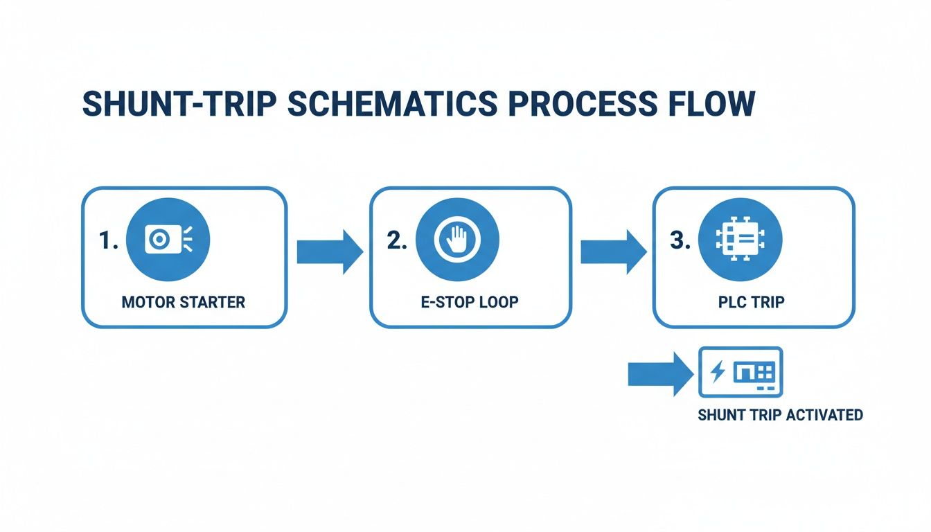
The graphic lays out three common wiring flows—motor-starter integration, emergency-stop loops and PLC-driven trips. Follow each color-coded path to see exactly how the control signal returns to the breaker coil.
Simulated Trip Tests
Now it’s time to make the breaker dance on command. Hit the manual pushbutton or trigger a trip via your PLC HMI and watch the mechanism snap open.
Running remote trips through SCADA or PLC outputs means fewer techs inside live cabinets. From my experience, this approach exposed a swapped terminal before it ever hit the line.
“A simulated trip once uncovered a missing fuse link that saved us hours of downtime.”
Field Lessons And Tips
- Adding a spare coil fuse in a packaging plant stopped all nuisance trips
- Swapping identical coils between breakers pinpoints wiring faults fast
- Log every test result with operator initials and timestamps for full traceability
Documentation For UL And NEC
UL and NEC inspections hinge on solid records. Capture torque readings, insulation values, voltage tests and simulated-trip outcomes in your commissioning report.
Key Documentation Elements
- Test criteria and acceptance thresholds
- Photos or screenshots of meter readings
- Signed test forms alongside updated schematics
Final Acceptance And Handover
Once tests pass, circle back to your wiring diagrams and log any final tweaks. That last sign-off proves you’ve met safety and performance benchmarks.
Assemble a handover packet for operations that includes:
- Revised wiring diagram for a shunt trip breaker
- Commissioning checklist with pass/fail entries
- Signed UL and NEC compliance certificates
- Tester and inspector initials on every document
When you wrap it up this way, the panel handoff isn’t just another formality—it’s a confidence-boosting milestone for everyone involved.
Troubleshooting And Safety Tips
When a shunt-trip breaker refuses to pull in, I zero in on the coil terminals first. Sliding a clamp meter over the leads quickly confirms whether you’re missing pickup voltage or chasing a phantom issue.
Sometimes the coil fires sporadically—usually the culprit is a loose lug or compromised insulation. A quick resistance check with your multimeter, compared to OEM specs, will separate a worn-out coil from a simple wiring hiccup.
False trips aren’t just annoying; they can mask serious wiring faults. I always isolate the control circuits to reveal voltage spikes or ground faults that sneak by standard checks.
- Use a calibrated digital multimeter for precise coil resistance
- Deploy a clamp meter to record inrush current during a simulated trip
- Inspect harnesses for chafed insulation or loose ferrules
- Confirm the shunt-trip coil sees proper voltage under load
Reading Coil Resistance
Begin by locking out the main power and tagging out all control transformers. Once the coil leads are free, measure resistance across T1 and T2. A healthy 120 VAC coil typically reads between 50 Ω and 150 Ω; anything beyond a ±10% variation demands closer attention.
Always confirm control-power isolation before probing terminals to avoid shock hazards and misleading readings.
Next, trace each conductor back to its origin. I label both ends of every coil wire to prevent swapped connections. Then I verify continuity to the PLC or relay output—loose terminations often only reveal themselves under load.
- Lock out main power at the breaker or disconnect switch
- Tag out the control transformer and test for zero voltage
- Ground test probes on the panel chassis before touching live circuits
Addressing NEC Violations
Undersized control wiring is a common NEC 110.14 violation that leads to overheating. Per Table 310.16, never go smaller than AWG 18 on AC coils.
| Coil Voltage | Minimum Wire Gauge |
|---|---|
| 24 VDC | AWG 22 |
| 120 VAC | AWG 18 |
Sticking precisely to your shunt-trip wiring diagram not only keeps you code-compliant but also boosts reliability. For an in-depth look at why breakers trip unexpectedly, check out our guide on what can cause a breaker to trip.
Voltage spikes often trigger nuisance trips. I recommend installing an RC snubber or flyback diode to tame those peaks once and for all.
Implement event logging on your PLC to capture trip signals and fault timestamps—your future self will thank you.
Final Testing And Documentation
I wrap up every commissioning session by documenting each test result right on my checklist. Capture insulation values, torque readings, and coil voltage under both no-load and full-load conditions.
- Photograph meter readings at key terminals
- Highlight any deviations from OEM specs and record corrective actions
- Store digital copies of test forms and updated schematics in your CMMS
Keeping these records alongside updated wiring diagrams streamlines maintenance and turns audits into a quick formality.
Frequently Asked Questions
How Do I Choose The Correct Coil Voltage
In most control panels, matching your coil voltage to the control supply is the simplest way to avoid nuisance trips. I’ve seen projects stall because someone spec’d a 120 VAC coil when the PLC only offered 24 VDC.
Here’s a quick rundown of common voltages:
- 12 VDC – favored by many PLC outputs
- 24 VDC – ideal for logic-driven shunt trips
- 120 VAC – standard on motor-starter transformers
- 240 VAC – typically reserved for E-stop circuits
Always double-check the OEM datasheet or your vendor’s wiring diagram before ordering parts. A few extra minutes of review saves hours in the field.
Coil-voltage mismatches cause more nuisance trips than you’d expect. Match first, troubleshoot later.
Which Protection Devices Are Required
Coils draw a hefty inrush current the instant they energize, and that surge can trash your control circuit if you’re unprotected. I never skip a dedicated fuse or mini-breaker sized for that inrush.
Beyond the primary fuse, I recommend:
- Fuse installed within 12 inches of the coil (NEC 240.4)
- Flyback diode on every DC coil to clamp voltage spikes
- RC snubber on AC coils when cabinet space allows
I’ve blown PCBs by ignoring transient spikes—adding a flyback diode is a tiny habit that pays huge dividends.
How Can I Integrate A PLC Trip Signal
Wiring a PLC-driven shunt-trip breaker means matching the PLC’s sink or source style to your coil voltage—and then labeling everything clearly. On a Square D QO, for example, you’d use COM and NO contacts (C3/NO3) and drop a flyback diode across the 24 VDC coil.
Key points:
- Confirm the PLC output handles your coil’s inrush
- Label COM and NO terminals right at the breaker
- Install the flyback diode directly on the coil for best noise suppression
On one plant startup, clear labels and proper diodes saved me a full day of debugging cross-wiring issues.
How Do I Apply UL/NEC Standards
When sketching schematics, UL 489 and NEC 240.4 guide every detail. They cover breaker accessories, fuse placement, conductor ampacity and more.
Don’t overlook:
- Conductor sizing and labeling per NEC table 310.16
- Torque specs on lugs and terminals
- Revision dates and clear schematic notes
Walk your panel regularly—check coil resistance, verify terminal torque, read labels. Those quick inspections keep unplanned downtime at bay.
Ready to optimize your next panel build? Partner with E & I Sales for premium UL-listed panels, expert wiring support, and reliable service.