
Wiring a shunt trip breaker isn't just about connecting a few wires. It's about installing a powerful safety device that allows you to kill power to heavy machinery from a distance. At its core, you’re hooking up a separate, low-voltage control circuit to a coil inside the breaker. When that coil gets a signal, it mechanically trips the main breaker. This setup is the bedrock of countless industrial safety and emergency stop systems.
Why Shunt Trip Breakers Are a Must-Have for Industrial Safety
Before you even think about stripping a wire, you need to grasp what this component really does. A shunt trip breaker is so much more than a standard overcurrent device—it's an active, on-demand safety tool designed for immediate remote intervention. Its entire purpose is to de-energize a circuit the moment it receives a command, protecting both your crew and your expensive equipment from disaster.
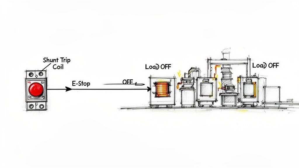
This isn’t just a convenience feature; it’s a lifeline. The internal shunt coil is basically a remote trigger. It allows an external signal—from an E-stop button, a fire alarm panel, or a PLC output—to instantly pop the breaker open.
Real-World Scenarios Where It Counts
Picture a CNC machine operator who sees a tool break and start chewing into the workpiece. Instead of making a mad dash for a panel on the other side of the shop, they can slam a big red mushroom button right next to them. That simple action fires a signal to the shunt trip breaker, killing power to the machine instantly and preventing a catastrophic failure.
I’ve seen this same principle save the day in all sorts of industrial settings:
- Manufacturing Lines: One E-stop can shut down an entire conveyor system, preventing a dangerous product pile-up or, worse, protecting a worker who gets caught in the machinery.
- Data Centers & Server Rooms: When a smoke detector goes off, it can trigger the shunt trip breakers to cut power to all the server racks and HVAC units, drastically reducing the risk of an electrical fire spreading.
- Elevator Machine Rooms: Fire codes often require shunt trip breakers to disconnect power to elevator motors when a heat or smoke detector is activated.
The real magic of a shunt trip breaker is its ability to centralize emergency control. It takes a regular circuit breaker and turns it into a responsive part of your facility's safety architecture, allowing for a coordinated, immediate response when things go wrong.
Before jumping into the wiring, it's helpful to have a clear picture of all the parts involved.
Essential Components for a Shunt Trip Breaker Installation
Here’s a quick rundown of the key players in a typical shunt trip circuit and what they do. Getting familiar with these components will make the whole process much smoother.
| Component | Primary Function | Key Consideration |
|---|---|---|
| Shunt Trip Circuit Breaker | The main device that interrupts the power circuit when its internal coil is energized. | Ensure the coil voltage matches your control circuit voltage (e.g., 24VDC, 120VAC). |
| Control Power Source | Provides the low-voltage power needed to energize the shunt trip coil. | Must be reliable and often separate from the main power being controlled. |
| Emergency Stop (E-Stop) Button | A normally closed (NC) or normally open (NO) pushbutton that initiates the trip signal. | NC contacts are typically used for fail-safe E-stop circuits. |
| Fire Alarm/Safety Relay | An interface that provides a dry contact closure to signal the breaker to trip. | Check the relay's contact rating to ensure it can handle the coil's inrush current. |
| Control Wiring | The conductors used to connect the control source, initiating devices, and the shunt trip coil. | Use the correct wire gauge and insulation type for the voltage and environment. |
Think of this table as your pre-flight checklist. Having the right parts on hand and understanding their roles is half the battle.
Meeting Safety and Code Requirements
Beyond the practical, on-the-floor safety benefits, shunt trip breakers are often a requirement for regulatory compliance. If you're building industrial control panels, you absolutely need to know how they fit into standards like UL 508A and the National Electrical Code (NEC).
The idea of tripping a breaker remotely has been around for a while. The first truly functional circuit breaker designs appeared back in the 1920s, and the technology has been evolving ever since to add more layers of control and safety.
Today, the NEC actually mandates shunt trip mechanisms in specific situations. Under NEC 240.87, breakers rated 1200 amperes or higher must have a means of energy reduction, and a shunt trip is a common way to meet this. The goal is to reduce deadly arc flash energy when a technician is working on the equipment. This shows just how much modern safety codes rely on this technology.
When you're installing a device like this, you're not just checking a box; you're participating in a much larger safety ecosystem. To get a better handle on the bigger picture, you might want to look into other essential safety topics for work. And for a deeper dive into the component itself, our guide explaining https://eandisales.com/uncategorized/what-is-shunt-trip/ is a great place to start. Understanding this context is critical before you start wiring a shunt trip breaker.
Preparing for a Safe Installation
Wiring a shunt trip breaker isn't something you just jump into. The real work—the smart work—starts long before you ever touch a wire. Getting your prep right isn't just about being efficient; it's about making sure you, and the equipment, are protected every step of the way.
Think of it as a pre-flight checklist for an electrician. Skipping a step because you're in a hurry is how simple jobs turn into dangerous situations. Let's walk through exactly what you need to have sorted out first.
Assembling Your Essential Toolkit
You can't do a professional job with bargain-bin tools. Using a worn-out screwdriver or a dull set of strippers is a great way to damage expensive components or create a loose, hazardous connection. Your toolkit needs to be built for this specific kind of electrical work, with a focus on insulated, high-precision gear.
Here’s a look at the non-negotiables for this installation:
- Insulated Hand Tools: At a minimum, you need a good set of Phillips and flathead screwdrivers, plus pliers and wire cutters all rated for 1000V. That insulation is your primary defense against an accidental shock.
- High-Quality Wire Strippers: A sharp, properly gauged stripper is key. It lets you slice through the insulation cleanly without nicking the copper conductor, which can create a weak point that fails under load.
- Calibrated Multimeter: This is your truth-teller. You'll need it to verify that circuits are truly dead and to check for continuity in your new control wiring. Don't ever trust a cheap, unreliable meter with your safety.
- Torque Screwdriver or Wrench: Breaker terminals have torque specs for a reason. Go too tight, and you can crack the terminal. Too loose, and you've just created a hot spot that could lead to a fire.
These tools aren't just for making the job easier; they're for creating solid, code-compliant connections that you can trust. And don't forget that the enclosure itself matters. It's worth understanding the different electrical boxes types you might encounter so you're ready for whatever the job site throws at you.
Personal Protective Equipment: The Unskippable Step
Anytime you're working inside an electrical panel, PPE is your last line of defense. Even with the main breaker off, you have to assume there’s a live circuit somewhere nearby. The risk of an arc flash from an adjacent, energized section is always a possibility.
Your absolute minimum PPE should be arc-flash rated for the specific hazard level of the panel you're opening up. This usually means:
- Arc-Rated (AR) Clothing: A long-sleeve shirt and pants made from flame-resistant material are a must.
- Safety Glasses or Goggles: Protecting your eyes from debris and the intense flash of an arc is non-negotiable.
- Voltage-Rated Gloves: These are absolutely critical for any task where you could potentially make contact with a live circuit.
Remember, PPE isn't a suit of armor. Its job is to minimize injury if the absolute worst happens. Don't ever get complacent just because you're geared up.
Establishing a Safe Work Zone with LOTO
The single most important safety procedure in our trade is Lockout/Tagout (LOTO). It’s a formal, documented process that ensures a circuit is completely de-energized and, more importantly, cannot be re-energized by someone else while you're working on it. It’s a literal lifesaver.
The process itself is straightforward, but you have to follow it to the letter. Start by identifying the correct upstream breaker or disconnect that feeds the panel or circuit. Switch it to the off position, then apply your personal lock and tag.
Once it's locked out, the crucial next step is to verify. Use your multimeter and test for voltage where you plan to work—phase-to-phase and phase-to-ground. Only after you’ve confirmed zero voltage is it safe to get your hands in there. For any job this critical, it's best practice to formalize your entire safety plan in a Safe Work Method Statement (SWMS). This document forces you to think through all potential risks and controls, including LOTO, before you even open your toolbox.
Alright, time to get our hands dirty—figuratively, for now—and walk through the actual wiring process. This is where the rubber meets the road, turning those diagrams and schematics into a safe, functioning installation. We’ll tackle this in two main parts: the heavy-lifting power wiring and the brains of the operation, the control wiring.
First things first, though. Safety is never an afterthought.
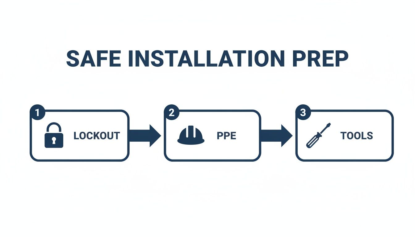
This workflow isn't just a suggestion; it’s the professional standard. You absolutely must lock out the power source, gear up with the right PPE, and have your tools ready before a single cover comes off. There are no shortcuts here.
Reading the Roadmap: The Shunt Trip Wiring Diagram
Before you touch a single wire, you have to be able to read the map. A shunt trip wiring diagram can look a bit busy at first glance, but it's telling a very simple story once you know the characters.
- The Circuit Breaker: You'll see the standard breaker symbol, but with a dotted line connecting it to a small box. That little box is our shunt trip coil.
- The Shunt Trip Coil (MX): This is the heart of the remote trip function. It's usually a rectangle labeled "MX" or maybe just a coil symbol. The most critical piece of information will be right next to it: the voltage rating (e.g., 24VDC, 120VAC). Getting this wrong is a recipe for a dead coil.
- The Control Power Source: This is a separate power source, completely independent of the main circuit the breaker is protecting. It'll look like a battery symbol for DC or a transformer for AC.
- The Initiating Device: This is whatever is sending the "trip now" signal. An E-stop button will be shown as a normally closed (NC) contact, while a signal from a fire alarm panel is typically a normally open (NO) dry contact.
The diagram shows a path: from the control power source, through the switch, over to the shunt coil, and back to the source. Your job is to build that path with real copper.
Laying the Foundation: The Power Circuit
Connecting the main power conductors is pretty standard stuff, identical to wiring any other circuit breaker. The goal is simple: solid, low-resistance connections that can safely carry the load current without breaking a sweat—or getting hot.
Start by sizing your conductors correctly for the breaker’s amp rating. Don’t guess; consult the NEC. Using undersized wire isn't just bad practice, it's a major fire hazard.
Next, nail the terminations. Strip the insulation cleanly without nicking the copper strands. Make sure the wire is seated all the way into the breaker's line (power in) and load (power out) lugs.
Here's the one step I see guys skip all the time: using a calibrated torque wrench. Every single manufacturer specifies a torque value for their terminals. Too loose, and you get a hot spot that will eventually fail. Too tight, and you can crack the lug. Get it just right.
Once your line and load conductors are properly torqued down, you're done with the power side. The breaker is now ready to do its primary job of protecting against overloads and shorts.
The Magic Ingredient: The Control Circuit
This is what separates a shunt trip breaker from the pack. The control circuit provides the remote tripping capability, and it’s where attention to detail really pays off.
Let's walk through a classic industrial scenario: wiring a 24VDC shunt trip coil to an E-stop button inside a UL 508A control panel.
- Find Your Points: First, locate the dedicated shunt trip terminals on the breaker itself. They’re much smaller than the power lugs and are often labeled S1 and S2 or something similar.
- Run the Signal Wire: Take the positive (+) wire from your 24VDC power supply and run it to one side of your E-stop's normally closed (NC) contact. From the other side of that contact, run a wire over to the S1 terminal on the breaker.
- Close the Loop: To complete the circuit, run a wire from the S2 terminal on the breaker back to the negative (-) or common terminal of your 24VDC supply.
Now, in a modern "fail-safe" system, the E-stop button doesn't trip the breaker directly. Instead, pressing the E-stop opens its contact, which signals a safety relay or PLC. That controller then closes a different contact, sending the 24VDC pulse to the shunt trip coil. This logic ensures the trip is an intentional command from the safety system.
From Functional to Professional: Clean Installation Tips
Getting it to work is one thing. Making it look professional and easy to maintain is another. A clean panel isn't just for show; it makes troubleshooting 10 times easier for the next person—which might be you.
- Label Everything: Seriously, everything. Use wire markers on both ends of your control wires. "SH-TRIP-1" on the wire going to S1 and "SH-TRIP-2" on the return wire will save you a massive headache later.
- Stick to Color Codes: Don't just grab any wire. In a UL 508A panel, DC control circuits are typically blue. Using the right color is like leaving a roadmap for future technicians.
- Practice Good Wire Management: Route control wires neatly in a wire duct (like Panduit). Never, ever run your low-voltage control wiring in the same bundle as high-voltage power conductors. This is crucial for preventing electrical noise that can cause phantom trips.
Taking a few extra minutes to follow these steps will make your work stand out and ensure the system is reliable for years to come.
Testing and Commissioning Your Shunt Trip Circuit
With all your wiring landed and looking clean, it's tempting to call it a day. But hold on—the most important part is just ahead.
Wiring a shunt trip breaker is all about building a reliable safety system. And any safety system is just a collection of parts until you've proven it works in a controlled test. Commissioning isn't just a final checkbox; it's what turns your installation into a verified, functional safety circuit you can trust.
This process has to be deliberate. Rushing through testing is a recipe for failure, either right now or, worse, during a real emergency. Let's walk through it step-by-step, starting with the essential checks you need to make before any power is applied.
Pre-Power Safety Verifications
Before you even think about flipping a switch, you need to perform several dead-circuit checks. Think of these as your first line of defense against wiring mistakes that could fry components or create a serious hazard when the power comes on.
First up is a simple continuity test on your control wiring. Grab your multimeter, set it to continuity or resistance, and make sure all power is locked out. Check the path from your control power source, through the E-stop button or other device, all the way to the shunt trip coil and back again. When the E-stop is in its normal, "run" position, you should see a complete circuit.
Next, you’ll want to do an insulation resistance test, especially for the main power conductors if they're new or have been moved around. This test is crucial for spotting any nicks in the wire insulation that could cause a dead short to ground. A failed insulation test means you have a serious problem that needs to be fixed before you go any further. For a more detailed guide, check out our article on how to perform a ground fault test.
These preliminary checks are non-negotiable. Finding a wiring mistake with a multimeter is a minor inconvenience. Finding one with 480V applied is a catastrophic failure. Take the time to verify your work while the circuit is safely de-energized.
Controlled Power-Up and Functional Testing
Once your dead-circuit checks are clear, it's time for a careful, phased power-up. The goal here is to energize circuits one at a time, starting with the control voltage.
First, with the main power still locked out, re-energize only the control power source (your 24VDC or 120VAC supply). Use your multimeter to confirm you have the correct voltage right at the shunt trip coil terminals.
Now for the moment of truth. Go ahead and activate your initiating device—press the E-stop button or manually close the fire alarm relay.
You should hear an immediate, distinct "clunk" from the circuit breaker as the shunt coil fires and mechanically trips the mechanism. The breaker handle will physically move to the tripped position, which is usually halfway between ON and OFF. That sound is confirmation that your control circuit is working perfectly.
Full System Verification
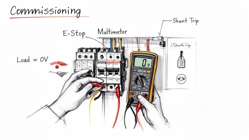
With the control side validated, the final step is to verify the whole system under normal operating conditions. This means it's time to re-energize the main power that the breaker is protecting.
Reset the breaker to the ON position and confirm power is flowing to the load. A quick check with your multimeter on the load-side terminals of the breaker will tell you everything is live.
Now, do it again. Activate your initiating device.
The breaker should trip instantly. Your multimeter reading on the load side should immediately drop to zero volts. This final test proves that your shunt trip breaker isn't just getting the signal—it's successfully killing power to the downstream equipment.
Troubleshooting Common Shunt Trip Wiring Issues
Even with a careful approach, things can go wrong. A breaker that doesn't trip, or one that trips unexpectedly, can be frustrating. This table breaks down some of the most common issues I've seen in the field and how to track down the root cause.
| Symptom | Potential Cause | Recommended Action |
|---|---|---|
| Breaker Fails to Trip | No control power to the coil | Verify control circuit breaker is ON. Check for correct voltage at the shunt coil terminals. |
| Faulty initiating device (E-stop, relay) | Test the device for proper continuity when activated. Replace if defective. | |
| Incorrect coil voltage | Ensure the coil voltage rating matches the control circuit supply (24VDC, 120VAC, etc.). | |
| Open circuit in control wiring | Perform a continuity test from the source, through the device, to the coil. Check all terminations. | |
| Defective shunt trip coil | If voltage is present at the coil but it doesn't activate, the coil itself is likely faulty and needs replacement. | |
| Breaker Trips Immediately on Reset | Control device is stuck in the "trip" state | Check E-stop buttons to ensure they are pulled out. Verify control relays are in their normal, non-tripped state. |
| Short circuit in control wiring | A "hot" wire may be shorted to the coil's input, bypassing the initiating device. Inspect wiring for damage. | |
| Breaker Trips Randomly | Unstable control power | Check for voltage fluctuations or drops in the control power supply that could falsely trigger the coil. |
| Loose control wiring connection | Vibration can cause intermittent connections. Re-check and tighten all screw terminals in the control circuit. | |
| Noise or induced voltage on signal wires | If control wires are run alongside high-power cables, electrical noise can induce a "phantom" trip signal. Reroute or use shielded cable. |
Always approach troubleshooting systematically. Start with the simplest potential cause—like a closed E-stop button—before moving on to more complex issues like intermittent connections or electrical noise. This methodical process will save you a lot of time and headaches.
Keeping Your System Compliant and Reliable for the Long Haul
Getting a shunt trip breaker wired up correctly is a great feeling, but the job isn't truly done once the power comes on. The real win is building a system that stays safe, compliant, and rock-solid for years. This is where we shift from a one-time install to creating a durable, easily managed safety asset.
This means looking past the immediate connections and thinking about the standards that govern industrial control panels. For anyone working in this field, the National Electrical Code (NEC) and UL 508A aren't just suggestions—they're the rulebooks that ensure everything is safe and works as expected.
Sticking to Industry Standards
You can't cut corners on compliance. It’s all about safety and liability. When you're adding a shunt trip breaker to an industrial control panel, you have to follow the playbook, and UL 508A has some very specific rules designed to make systems predictable, safe, and easy to service.
One of the most obvious rules is wire color-coding. Getting the colors right isn't just about making the panel look neat; it's a universal language for every electrician who might work on it down the road.
- Red Wires: The go-to for ungrounded AC control circuits, like the 120VAC signal heading to your shunt coil.
- Blue Wires: Standard practice for ungrounded DC control circuits. Think of a 24VDC signal coming from a safety PLC.
- White or Gray Wires: These are reserved for grounded AC current-carrying conductors.
- White with a Blue Stripe: This specific combination is for a grounded DC current-carrying conductor.
Following this code makes future troubleshooting ten times faster and safer. It's not just about colors, either. Standards also spell out requirements for component spacing to manage heat buildup and prevent electrical arcing, ensuring the whole assembly is sound.
The final piece of the compliance puzzle is solid documentation. An updated electrical schematic that clearly shows the new shunt trip circuit isn’t optional. Tape it inside the panel door. It becomes the permanent record for anyone doing maintenance or troubleshooting.
Built on a Foundation of Proven Technology
As you integrate these modern control features, it’s good to remember they’re built on incredibly refined technology. Circuit breaker interruption has seen huge leaps forward, with innovations like vacuum interrupters and SF6 gas technology setting new benchmarks for safety and reliability.
Today’s shunt trip breakers are direct beneficiaries of these advancements. This solid foundation lets the remote trip mechanism do its precise job—activating from a distance—while leaning on decades of R&D focused on reliably snuffing out dangerous fault currents. If you're curious about the history, you can explore the evolution of circuit breaker design.
A Practical Checklist for Long-Term Reliability
A safety device you never test is a safety device you can't trust. The only way to know your shunt trip circuit will work when it matters most is to set up a routine maintenance and testing schedule. This checklist is a great starting point for any plant engineer.
Quarterly Visual Check:
- Inspect Connections: With the panel de-energized and locked out, give all the control wiring terminations a once-over. Check the breaker, power supply, and initiating device. Look for any discoloration that could signal overheating.
- Scan the Components: Look for excessive dust, signs of moisture, or any visible wear and tear on the breaker and control hardware.
- Check the Labels: Make sure all wire labels and component tags are still in place and easy to read.
Annual Functional Test:
- Schedule Downtime: First thing's first—work with the operations team to schedule a brief, planned outage for whatever equipment the breaker protects.
- Run a Live Trip Test: With all safety protocols in place, activate the initiating device. Push that E-stop button or trigger the sensor.
- Confirm the Trip: You should hear a solid, distinct "clunk" as the breaker trips. Verify that power to the load has been cut completely.
- Reset and Record: Reset the breaker and the initiating device. Most importantly, log the date, time, and result in your maintenance records.
This simple, repeatable process turns your installation project into a managed safety system. It's the only way to guarantee it will be ready to go, year after year.
Got Questions? We've Got Answers.
Even the best guides can leave you with a few lingering questions when you're elbows-deep in a project. Let's tackle some of the most common things we get asked about wiring up shunt trip breakers.
Can I Still Use It for Regular Overcurrent Protection?
Yes, absolutely. Think of a shunt trip breaker as a standard circuit breaker with an extra trick up its sleeve. It will still do its primary job—providing reliable protection against overloads and short circuits—just like any other breaker in your panel.
The shunt trip coil is a completely separate component inside. It just sits there, waiting for an external voltage signal, and doesn't interfere with the breaker's main protective functions in any way.
What Happens if the Shunt Trip Coil Burns Out?
This is a pretty common failure, and it almost always happens for one reason: the control voltage was applied for too long. If the coil fries, you'll lose the ability to trip the breaker remotely. That's it.
The good news is the breaker will continue to operate normally for overcurrent protection. To get the remote trip working again, you'll have to replace either the shunt trip accessory itself or the entire breaker, depending on the model.
A shunt trip coil is designed for a quick jolt of power, not a continuous-duty one. We're talking less than a second. Any longer and it'll overheat and burn out. This is exactly why a well-designed control circuit includes a micro-switch (an auxiliary contact) that cuts power to the coil the instant the breaker trips.
Is an Auxiliary Contact Really Necessary?
Strictly speaking, no, the shunt trip will function without one. But in any real-world industrial control system, it's absolutely essential. I'd go so far as to say it's a must-have.
Here's why: the shunt trip coil's job is to trip the breaker. The auxiliary contact's job is to report the breaker's status (ON/OFF/TRIPPED) back to your PLC or alarm system.
Without that auxiliary contact, your control system is flying blind. It sends the signal to trip but has no way to confirm the breaker actually opened. It's the critical feedback loop that makes a safety system truly reliable.
Can I Manually Reset a Breaker After a Shunt Trip?
Of course. A shunt trip is just a mechanical action, not some kind of permanent lockout. Once the shunt coil does its thing, you reset the breaker exactly like you would after an overcurrent trip.
- First, push the handle all the way to the full OFF position.
- Then, flip it back to the ON position.
Just remember, if the signal that caused the trip in the first place (like a pressed E-stop) is still active, the breaker will just trip again immediately. You have to clear the initial fault before you can successfully reset the breaker.
At E & I Sales, we don't just sell parts; we build complete, engineered solutions. From helping you spec the right shunt trip breaker to designing and building a fully UL 508A-certified control panel, our team has the field-tested expertise to make sure your safety systems are compliant, reliable, and built to last.