
Before you even think about pulling wire, it’s critical to understand what a shunt trip breaker really is. This isn't your standard overcurrent device; it's an intelligent safety switch. Its entire purpose is to give you the power of remote, instantaneous disconnection when an external signal—like an E-stop or fire alarm—tells it to act. This single feature elevates a simple electrical panel from a passive box to an active player in your facility's safety system.
Understanding the Role of a Shunt Trip Breaker
A normal circuit breaker only cares about one thing: electrical problems like overloads and short circuits. That's essential, of course, but it leaves a massive safety gap. A standard breaker has zero awareness of a fire breaking out, a gas leak, or a critical machine going haywire. This is exactly where the shunt trip breaker comes in.
It works by adding an electromagnetic coil (the "shunt coil") to the breaker's internal mechanism. This coil allows the breaker to be tripped by a separate, low-power control signal. In simple terms, you're giving your electrical system ears. Now, it can listen for commands from other safety systems scattered throughout your building.
Real-World Applications and Why They Matter
The real value of a shunt trip breaker clicks into place when you look at scenarios where cutting power right now is absolutely non-negotiable. Without it, energized equipment can become a deadly hazard for first responders or make a bad situation infinitely worse.
You’ll see them in all sorts of industrial and commercial settings:
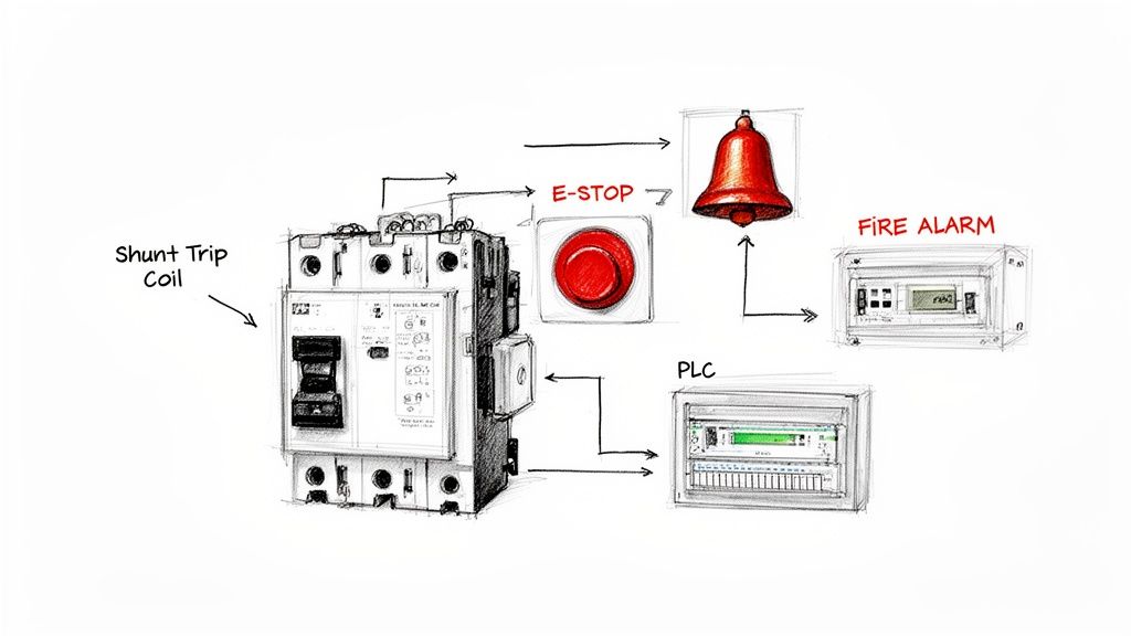
- Emergency Stop (E-Stop) Circuits: Think about manufacturing lines, CNC machines, or conveyor systems. An operator hits a big red button, and a signal instantly fires to the shunt trip, killing power to the machinery and preventing a serious injury.
- Fire Alarm Integration: When a smoke or heat detector goes off, the fire alarm panel can trigger the shunt trip to de-energize an entire electrical room or specific high-risk equipment. This is a huge step in preventing an electrical fire from spreading.
- Automated System Faults: A Programmable Logic Controller (PLC) monitoring a critical process can be programmed to trip the main breaker via its shunt coil if it detects a dangerous condition, like a tank over-pressurizing or a motor overheating.
Here's the key takeaway: a shunt trip breaker doesn't replace standard overcurrent protection—it adds a second, totally independent way to trip. You get both automatic fault protection and remote emergency control, all packed into a single device.
Integrating shunt trip breakers is often a core part of a facility's overall fire safety strategy. For a deeper dive on this, check out these guides on warehouse fire safety protocols. This kind of integration is becoming less of a "nice-to-have" and more of a requirement for compliance and keeping people safe. If you're looking for specifics on components, you might want to look at our guide on the ABB circuit breaker series and all the accessories available.
https://eandisales.com/uncategorized/abb-circuit-breaker/
The demand for these devices tells the story. The global market for shunt trips has already hit around USD 1.1 to 1.2 billion, which shows just how critical they've become in modern electrical design. As more facilities move toward automated safety systems, that number is only going to climb. Getting a handle on these applications is the first, most important step before you start the hands-on work of wiring one up.
Getting Your Gear and Safety Straight
Before a single wire gets connected, let's talk about prep work. Getting organized now, with the right parts and a safety-first mindset, is what separates a smooth installation from a costly, frustrating one. Think of this as the pre-flight checklist for your shunt trip breaker install.
Nailing this stage means you avoid that dreaded pop when mismatched voltage instantly fries a brand-new coil. More importantly, it ensures you walk away from the job safely, which is always priority number one.
The Essential Parts List
At its core, this setup is all about a few key pieces working together in perfect harmony. I can't tell you how many service calls I've been on where the root cause was simply mismatched components. Double-check every single spec before you start.
Here's your shopping list:
- The Shunt Trip Breaker: This is the star of the show. Make sure it has the right amperage rating for your load circuit. Critically, its shunt coil voltage must match your control circuit voltage.
- A Control Voltage Source: This is the power that actually trips the breaker. It's totally separate from the high-voltage power flowing through the breaker. You'll typically use a 24V DC power supply or a 120V AC control transformer.
- An Actuating Device: This is your trigger. It could be a big red mushroom-head Emergency Stop (E-Stop) button, a dry contact from a fire alarm panel, or even an output from a PLC.
- Control Wiring: Grab some properly sized and color-coded wire. For most control circuits, 18 AWG or 16 AWG wire is plenty, but always check your local codes, especially if you have a long wire run.
A Tip From the Field: The number one mistake, hands down, is smoking the shunt coil with the wrong voltage. A 24V DC coil will vaporize instantly if you hit it with 120V AC. Always, always read the fine print on the breaker or the accessory module to confirm the coil voltage, and then match your control power source to it precisely.
Your Non-Negotiable Safety Checklist
Let's be clear: working inside a live electrical panel is dangerous business, even for seasoned pros. Complacency is the real enemy here. Before your hands go anywhere near a terminal, you absolutely must establish a safe work condition. This isn't just a suggestion; it's a life-saving discipline.
Lockout/Tagout (LOTO) Is Not Optional
This is always your first move. Never, ever assume a panel is dead just because a switch is in the "off" position.
- Find the Source: First, identify the main breaker or disconnect that feeds the panel you're about to open up.
- Lock It Out: Flip that breaker to the "Off" position and slap your personal lock and tag on it. Your tag needs to say who you are and why that circuit is locked out.
- Prove It's Dead: This is the step people tragically skip. Get out a multimeter you trust and test for voltage. Check everything: phase-to-phase, phase-to-neutral, and phase-to-ground. You need to be 100% certain there is zero energy. A good habit is to test your meter on a known live source first (like a wall outlet) to make sure it's working before you trust it with your life.
Suit Up with the Right PPE
Your Personal Protective Equipment (PPE) is your last line of defense if something goes wrong. The exact level of PPE you need depends on the arc flash hazard rating of the equipment, but for most control panel work, this is a solid baseline.
- Safety Glasses: A no-brainer. Protect your eyes from flying debris or the intense light of an arc flash.
- Insulated Gloves: Class 0 gloves, rated for up to 1000V, are the standard for this kind of work. Give them a quick inspection for pinholes or tears before every single use.
- Flame-Resistant (FR) Clothing: A long-sleeve FR shirt and pants provide that crucial barrier against the intense heat of an electrical incident.
Alright, with your parts verified and your safety protocols locked in, you've laid the groundwork for a clean, professional job. Now you’re ready to start pulling wires.
Alright, with your components in hand and safety procedures locked in, it's time to wire this thing up. Connecting a shunt trip breaker isn't rocket science, but it absolutely demands precision. One wrong wire, and you could have a coil that fails to fire in an emergency or, just as bad, a coil that fries itself the second you power up the control circuit.
The core idea is simple: you're building a separate, low-power circuit that has one job—to tell the main breaker when it's time to trip. This control circuit is completely isolated from the heavy-duty power flowing through the breaker's main terminals. Getting this part right is everything.
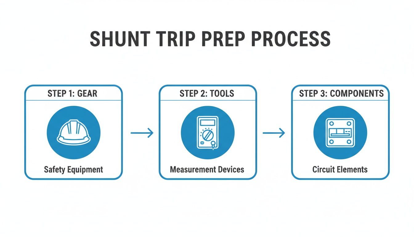
This whole process really starts before you even touch a wire. As the flow shows, having the right gear, tools, and verified components is the foundation for a successful and safe installation.
Locating Your Connection Points
First things first, you need to find where to land your wires. On most modern breakers, the shunt trip accessory is a small module that either ships pre-installed from the factory or simply snaps onto the side of the breaker. It will have two dedicated screw terminals, often labeled S1 and S2, or sometimes just marked with the coil's rated voltage (like "24VDC" or "120VAC").
These two little screws are your targets. It's critical not to confuse them with terminals for other accessories, like an auxiliary contact or an undervoltage release. When in doubt, always pull up the manufacturer's datasheet—it's the only way to be 100% sure you've found the right spot.
Wiring for a Single E-Stop Button
Let's walk through the most common setup out there: connecting a shunt trip breaker to a single, normally open (NO) Emergency Stop button. This is your classic "energize-to-trip" circuit.
- Power to the Switch: Run a wire from the positive (+) terminal of your control power source (a 24V DC power supply is a common choice) over to one side of the E-stop button's normally open contact block.
- Switch to the Breaker: From the other side of that E-stop contact, run another wire to one of the shunt trip terminals on the breaker (we'll call it S1).
- Complete the Loop: Finally, run a wire from the second shunt trip terminal (S2) all the way back to the negative (-) or common terminal of your control power supply.
That’s it. In its normal state, the circuit is open, and the coil sees no power. But the moment someone slaps that big red button, the contact closes, the circuit is completed, and voltage zips over to the shunt coil, tripping the breaker instantly.
Handling Multiple E-Stops in Series
On larger machinery, you’ll often find several E-stop buttons located at different operator stations. You need any one of them to kill the power. The way to do this is by wiring the E-stop buttons in series.
- Start by running power from your source to the input of the first E-stop.
- Then, you simply "daisy-chain" from the output of the first button to the input of the second, and so on down the line.
- The output of the very last E-stop in the chain is what finally connects to the shunt trip coil.
With this configuration, pressing any button in the series breaks the chain, completing the circuit to the coil and tripping the breaker. It's a standard, bulletproof safety design.
Expert Insight: It’s easy to forget just how critical these components are. The total market for circuit breakers was valued at USD 22.70 billion and is projected to hit USD 30.32 billion by 2030. The low-voltage segment, where shunt trips are most prevalent, makes up a staggering 66.7% of that market. This just goes to show how fundamental these safety devices are in almost every modern electrical system. You can get more details from these circuit breaker market trends and forecasts.
The wiring for shunt trip circuits can vary based on what's triggering the trip. Below is a quick-reference table showing some of the most common control scenarios you'll encounter in the field.
Wiring Diagrams for Common Shunt Trip Scenarios
| Control Scenario | Actuating Device | Key Wiring Consideration | Diagram Reference |
|---|---|---|---|
| Emergency Stop | Normally Open (NO) E-Stop Pushbutton | Circuit is completed when the button is pressed, energizing the coil. | Classic "energize-to-trip" schematic. |
| PLC Control | PLC Relay Output | PLC logic determines when to close the relay, sending power to the shunt coil. | Connect PLC output as you would a simple switch. |
| Fire Alarm System | Fire Alarm Control Panel (FACP) Relay | The FACP relay closes on alarm, tripping the breaker to shut down equipment like HVAC units. | Wire in series with the FACP's dedicated normally open relay contacts. |
| Process Monitoring | Pressure or Temperature Switch | A normally open switch closes when a process variable (e.g., high pressure) is exceeded. | Ensure the switch is rated for the control circuit voltage and current. |
Each of these setups follows the same basic principle: a switch closes to send power to the shunt trip coil. The only thing that changes is what is telling that switch to close.
Momentary vs. Continuous Duty Coils
This is a detail that trips up a lot of people and can easily lead to a failed component. Shunt trip coils generally come in two flavors, and mixing them up is a recipe for a burnt-out coil.
- Momentary Duty Coils: These are the most common. They are designed to handle a very short burst of power—just long enough to activate the trip mechanism. They cannot be energized continuously.
- Continuous Duty Coils: These are built tougher and can have voltage applied to them for long periods without overheating or failing.
So, what happens if an operator panics and holds down an E-stop button connected to a momentary coil? You can probably guess. To prevent this, you need a little help from an auxiliary contact.
Using an Auxiliary Contact for Coil Protection
An auxiliary contact is a small, inexpensive switch that clips onto the breaker and mirrors its state. When the breaker is on, the contact is in one position; when it trips, it flips to the other. By wiring this into your control circuit, you can create a self-interrupting loop that protects the shunt coil.
Here’s how you modify the wiring:
- Wire your control circuit just like before, but this time, run the wire heading to the shunt coil through a normally closed (NC) auxiliary contact on the breaker first.
- Now, when the E-stop is pressed, power flows through the closed auxiliary contact, hits the shunt coil, and trips the breaker.
- The instant the breaker trips, the auxiliary contact opens up, immediately cutting power to the shunt coil—even if the E-stop button is still being held down.
This simple addition acts as a built-in safety for the coil itself. It’s cheap insurance that prevents a very common failure and is considered a best practice anytime you wire a shunt trip breaker with a momentary-duty coil.
Getting It Right: UL 508A and NEC Code Compliance
When you wire a shunt trip breaker, you’re not just connecting a few wires. You're engineering a safety circuit, and that means you have to play by the rules. For anyone building or modifying industrial control panels, the two most important rulebooks are the National Electrical Code (NEC) and UL 508A, the Standard for Industrial Control Panels.
Getting this right isn’t optional. It’s about building a panel that's safe, certifiable, and won't get you red-tagged by an inspector. An inspector doesn't care if your circuit seems to work; they care if it was built to code with the right components and methods. This is where your attention to detail really pays off.
Conductor Sizing and Color Coding
The wires you choose for that control circuit are just as critical as the breaker itself. UL 508A is very specific about this to ensure safety and make future troubleshooting manageable.
- Wire Sizing: For most control circuits, 18 AWG or 16 AWG wire gets the job done. But don't just guess—always check the breaker manufacturer's specs. You also need to factor in the length of your wire run to avoid any significant voltage drop.
- Color Coding: This is a big one. UL 508A lays out a strict color scheme so anyone opening that panel knows exactly what they're looking at. For AC control circuits under 120V, ungrounded conductors must be red. For DC control circuits, they must be blue.
A Word from Experience: Don't mess around with wire colors. I've seen inspectors fail an entire panel just for incorrect color coding. It's considered a major safety hazard for the next person who has to service that equipment, and it's an easy thing to get right from the start.
Protecting Your Control Circuit
Think of your shunt trip circuit as its own little system. And just like any other control circuit, it needs its own overcurrent protection. This is almost always handled by adding a correctly sized fuse or supplementary protector on the primary side of the control power transformer.
That little fuse is doing a huge job. If a fault happens in your control wiring—maybe a wire chafes and shorts to the panel—that fuse will pop instantly. This prevents catastrophic damage to your transformer and keeps a minor issue from becoming a dangerous arc flash event. It's a fundamental layer of protection. If this is new territory, it's a good idea to brush up on the fundamentals of good industrial control panel design.
Don't Forget the Short Circuit Current Rating (SCCR)
Every single component you add to a panel affects its overall Short Circuit Current Rating (SCCR), which is the maximum fault current the equipment can handle safely. This includes the control power transformer and the fuse you just added.
You absolutely have to use UL-listed and properly rated components. If you grab a non-listed transformer or an undersized fuse, you’ve just created a weak link that can drag down the entire panel's SCCR. It’s crucial that the SCCR of your control circuit components meets or exceeds the available fault current at that point in the system.
Finish the Job with Documentation and Labeling
Once the wiring is done, you're not finished. A compliant installation is a well-documented one.
You need to update the panel’s electrical schematics to reflect the new shunt trip circuit. Be detailed: show the wire numbers, component IDs, and terminal block locations.
Inside the panel, use clear, permanent labels. A label right by the control power transformer should spell out its purpose and identify the fuse protecting it. Proper documentation ensures the next person who works on that panel can do their job safely and efficiently. To make sure your work meets all legal and safety standards, resources covering general building codes and regulations can be incredibly valuable.
Testing and Troubleshooting Your Installation
An installation isn't complete just because the last screw is tightened. When you wire a shunt trip breaker, you're creating a life-safety circuit, and that demands rigorous testing before you can confidently walk away.
This final step, commissioning, is where you prove the system works as designed. It's your chance to hunt down any gremlins before they can cause real problems down the road.
The process isn't complicated, but it has to be systematic. A haphazard approach can miss critical issues or, even worse, create a false sense of security.
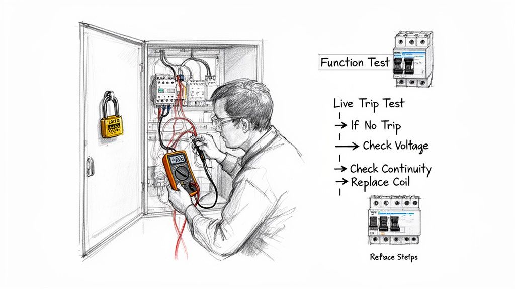
Performing a Safe Function Test
Your first round of testing should always be done with the main power to the breaker safely locked out. This "dry run" is all about verifying your control circuit wiring without introducing any high-voltage hazards.
Here's how I approach it:
- Confirm LOTO: First thing's first—double-check that the main breaker feeding the circuit is locked and tagged out. Get your meter out and verify zero voltage on both the line and load side terminals. No exceptions.
- Energize the Control Circuit: With the main power safely off, it's time to energize your low-voltage control circuit. Go ahead and turn on the control transformer or 24V DC power supply.
- Activate the Trigger: Now, press the E-stop button or manually close whatever relay contact is supposed to fire the shunt trip coil.
- Listen and Look: You should hear a distinct and solid "clunk" from the breaker. That's the sound of the shunt coil's plunger mechanically forcing the trip mechanism. The breaker handle should snap right to the tripped (center) position.
If you get that satisfying clunk, you've just confirmed your control wiring is solid, the coil is getting the right voltage, and the mechanical linkage is doing its job. Now you can reset the breaker and move on to a live test.
Live Testing in a Controlled Environment
The final proof is tripping the breaker under its normal operating load. This is the only way to confirm it can interrupt the current cleanly and effectively.
Before you begin, make sure all personnel are clear of the equipment. Then, re-energize the main power to the breaker.
With the machinery or load running as it normally would, activate the shunt trip control (like pressing that big red E-stop). The breaker should trip instantly, and the load should de-energize immediately.
Once that's confirmed, your installation is officially commissioned. But what if it doesn't work?
Common Problems and How to Fix Them
Even with the most careful work, issues can pop up. Let's walk through some of the most common failure modes I've seen in the field.
When a shunt trip system acts up, the problem is almost always in the control circuit, not the breaker itself. This quick troubleshooting guide covers the usual suspects.
Troubleshooting Common Shunt Trip Circuit Issues
| Symptom | Potential Cause | Recommended Action |
|---|---|---|
| Breaker won't trip | No voltage at the coil. | With the trip activated (E-stop pressed), measure voltage at terminals S1 and S2. Trace the circuit backward from there if voltage is missing. |
| Breaker won't trip | Loose control wire connection. | Power down and LOTO the control circuit. Gently tug on every wire at every terminal point—you'll be surprised how often this is the culprit. |
| Breaker won't trip | Burned-out shunt coil. | With all power off, check the coil's resistance with a multimeter. An open loop (OL or infinite resistance) means the coil is dead and needs replacement. |
| Breaker trips randomly | Short in the control wiring. | Visually inspect the control wiring run for any nicks, cuts, or chafed insulation that could be grounding out to the panel enclosure. |
| Breaker trips randomly | Induced or "phantom" voltage. | If control wires run parallel to high-power conductors for a long distance, induced voltage can sometimes be enough to activate the coil. Reroute the wiring if possible. |
After running through these checks, you'll have a much clearer picture of what's going on.
A dead coil is often the result of applying the wrong voltage. If you find a bad coil, it’s absolutely crucial to verify your control power source is correct before installing a new one, or you’ll just burn out the replacement in a heartbeat.
If you're dealing with nuisance tripping that isn't related to the shunt circuit, exploring other common causes of breaker trips can provide some additional context. A systematic approach to troubleshooting ensures your safety circuit is not just installed, but truly reliable.
Shunt Trip Wiring: Your Questions Answered
Even the best-laid plans run into hiccups in the field. When you're wiring a shunt trip breaker, you're bound to have questions pop up. Maybe it's a unique component, or the circuit just isn't behaving the way you expect. Let's tackle some of the most common questions I hear from technicians during installation and troubleshooting.
Think of this as your go-to guide for those "what if" moments. Nailing these details is what makes the difference between a safety circuit that just works and one that's truly reliable for the long haul.
Can I Use One E-Stop to Trip Multiple Breakers?
Yes, you absolutely can, and it's a pretty common setup in industrial machinery. The trick is to wire the shunt trip coils in parallel.
Here’s how you do it: run your control voltage from the E-stop switch to the S1 terminal on the first breaker. From there, you just jump a wire from that S1 terminal over to the S1 on the next breaker, and so on down the line. You'll do the exact same thing for the S2 terminals, creating a common return path back to your control power source.
A word of caution: make sure your power supply is up to the task. Every coil you add increases the total current draw. Before you start wiring, add up the amperage for all the shunt coils and double-check that your control transformer or DC power supply can handle the load. You need enough juice to fire them all at once without the voltage taking a nosedive.
What Is the Difference Between a Shunt Trip and an Undervoltage Release?
This is a big point of confusion, but it's critical to get right. While they might look similar and even plug into the same accessory port on the breaker, they work in completely opposite ways.
- Shunt Trip: This is an "energize-to-trip" device. You have to apply voltage to its coil to make the breaker trip. If there's no power going to it, it just sits there. This makes it perfect for things like emergency stops or fire alarm signals that actively send a trip signal.
- Undervoltage Release (UVR): This is an "energize-to-close" device. Its coil needs to be continuously powered just to keep the breaker closed. The moment that control voltage is lost—whether from a power outage or a broken wire—the UVR immediately trips the breaker. It's a fail-safe device for protection against a loss of control power.
Why Won’t My Shunt Trip Breaker Reset?
So, you’ve hit the E-stop, and now the breaker handle is stuck and won't reset. Don't force it. This is almost always a sign that the shunt trip coil is still energized.
The root of the problem is usually in your control circuit. If the E-stop button is still mashed in or a fire alarm relay is still latched, your circuit is sending a constant stream of power to the coil. Most breakers have a built-in mechanical interlock that physically stops you from resetting them while that coil is active.
The fix is simple: clear the signal. Twist and pull to reset the E-stop or clear the alarm condition. As soon as the voltage to the coil is cut, the breaker should reset without any trouble. If it's still stuck after that, you might have a mechanical jam in the trip mechanism itself.
At E & I Sales, we live and breathe this stuff. We provide the engineered components and system integration expertise you need for control solutions that are reliable and code-compliant. Whether you’re designing a new UL control panel or just upgrading some old equipment, our team is here to help you get the right breakers and accessories for the job. Learn more at https://eandisales.com.