
Voltage drop formulas are more than just textbook equations; they are the tools we use every day to make sure electrical circuits work safely and do their job right. For a standard single-phase system, we often lean on the formula VD = 2 x K x I x L / CMA to figure out how much voltage we'll lose from the panel to the load.
Why Understanding Voltage Drop Is Non-Negotiable
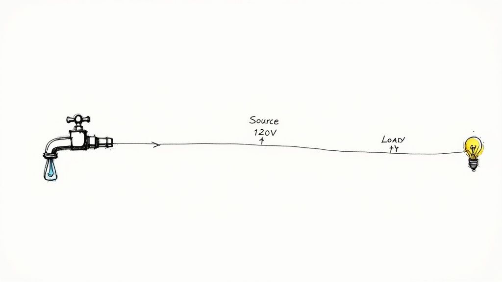
Here's a simple way to think about it. Imagine your electrical system is a garden hose. The water pressure you get at the nozzle is always going to be a little less than what's coming out of the spigot, right? The longer the hose, the more pressure you lose. That's a perfect real-world picture of voltage drop—the unavoidable loss of electrical "pressure" as current flows down a wire. It’s a natural result of a conductor's resistance.
A tiny drop is totally normal and expected. But when that drop gets too big, it becomes a silent killer of performance and a major safety concern. If the voltage reaching a piece of equipment is too low, you’re opening the door to a whole host of problems that can compromise your entire system.
The Real-World Consequences of Ignoring Voltage Drop
Out in the field, ignoring a proper voltage drop calculation has real, tangible consequences. We see it all the time. Equipment starts acting up, fails way too early, or creates genuinely hazardous situations.
The most common headaches include:
- Poor Equipment Performance: Motors might run hot or lack the torque they need, which drastically shortens their lifespan. You'll see lights that flicker or look dim, and sensitive electronics can glitch out or just shut down completely.
- Energy Waste and Overheating: That "lost" voltage doesn't just vanish—it turns into heat in the wire. Not only does this waste energy and drive up the power bill, but it can also make conductors overheat, melting the insulation and creating a serious fire risk.
- Non-Compliance with Standards: The National Electrical Code (NEC) gives us clear guidelines to follow. For instance, NEC 210.19(A) recommends keeping voltage drop on a branch circuit to a maximum of 3%. If you blow past these limits, you're looking at failed inspections and expensive do-overs.
Empowering Your Designs with Accurate Formulas
For anyone designing or installing electrical systems, getting a handle on voltage drop formulas isn't optional—it's fundamental. These calculations are what allow you to pick the right size wire for a specific load and distance, guaranteeing that equipment gets the voltage it needs to run properly.
A huge part of this is knowing how to express the voltage drop as a percentage of your starting voltage. If you need a quick refresher on the concept, checking out a guide on understanding percentages can be incredibly helpful.
Of course, with AC circuits, other factors like impedance and the load's power factor come into play and can affect voltage loss. We dive deeper into this in our guide explaining the power factor definition and its impact. By getting ahead of these variables, you're not just building a system that's safe and efficient—you're building one that's tough and reliable for years to come.
Cracking the Code: The Variables in Every Voltage Drop Formula
Before you can punch numbers into a calculator, you have to speak the language. Think of each voltage drop formula as a short sentence—the variables are the words, and you need to know what they mean to understand the story.
Getting this right is everything. It’s like baking a cake; you wouldn't just start throwing ingredients in a bowl without knowing the difference between flour and salt. In our world, mixing up the variables leads to circuits that are inefficient at best and unsafe at worst.
Let's break down the essential players one by one.
Current (I): The Electrical Workload
Current (I), measured in Amperes (Amps), is the amount of electricity actually flowing through the wire. Remember our garden hose analogy? Current is the volume of water you're trying to push through. The more water, the more pressure you lose from end to end.
It’s the same with electricity. The higher the current, the bigger the voltage drop. A beefy motor pulling 20 Amps is going to cause a much more significant voltage sag than a small LED light pulling 1 Amp, even on the same exact wire. Simply put, current is the primary driver here—it’s the workload you’re asking the circuit to handle.
Length (L): How Far the Electrons Have to Travel
Length (L) is the one-way distance the wire runs, from the panel to the piece of equipment. You'll typically measure this in feet (ft).
Now, here’s a critical detail: electricity needs a complete path to flow. It has to go out to the load and back to the source. The good news is that most common voltage drop formulas already account for this round trip by including a multiplier (like the number 2 for a standard single-phase circuit).
The logic is straightforward. The longer the wire, the more resistance the current encounters, and the more voltage you lose. A 200-foot run will have twice the voltage drop of a 100-foot run, all else being equal.
Here's a classic rookie mistake: using the total wire length (for example, 200 feet out and 200 feet back = 400 feet) for 'L' when the formula already has a built-in multiplier for the round trip. Always use the simple one-way distance for 'L' to avoid accidentally doubling the length and getting a wildly incorrect result.
Conductor Properties: The Wire Itself
The wire you choose plays a huge role, and it comes down to two main things: what it’s made of and how big it is.
- The 'K' Factor: This is just a simple constant that represents the electrical resistivity of a given material. It saves you from doing messy physics calculations on the fly. For copper, the K-factor is around 12.9. For aluminum, it’s higher, at about 21.2. That tells you aluminum is more resistive than copper, so it will cause a larger voltage drop for the same size and length.
- Circular Mils Area (CMA): This is the cross-sectional area of the wire. Think of it as the width of the pipe. A bigger wire has a higher CMA, giving the electrons more room to flow and reducing the overall resistance. Voltage drop and CMA have an inverse relationship—when you increase the wire size (a bigger CMA), the voltage drop decreases.
These four pieces—Current (I), Length (L), K-Factor (K), and CMA—are the foundational building blocks you'll find in almost every basic voltage drop formula. Once you get a feel for how they interact, you'll be able to tackle these calculations with confidence on any job.
To make it even clearer, here’s a quick-reference table summarizing these key players.
Table: Key Variables in Voltage Drop Formulas
| Variable Name | Symbol | Standard Unit | Impact on Voltage Drop |
|---|---|---|---|
| Current | I | Amperes (Amps) | Increases voltage drop. More current means more loss. |
| Length | L | Feet (ft) | Increases voltage drop. Longer wires mean more loss. |
| Conductor K-Factor | K | (Constant) | Increases voltage drop. Higher K means more resistance. |
| Circular Mils Area | CMA | Circular Mils | Decreases voltage drop. Larger wires mean less loss. |
Keep this table handy as you start working through the formulas. Seeing how each variable pushes the final result up or down is the key to truly understanding what’s happening in your circuits.
Alright, let's get this section sounding like it was written by an experienced pro who's spent years in the field. Here’s a complete rewrite, focusing on a natural, human voice while preserving all the critical technical details.
Running the Numbers for DC and Single-Phase Circuits
Now for the fun part. We've talked about the "what" and "why" of voltage drop, but it's time to put these concepts to work. This is where we take the theory off the page and start plugging in real numbers to solve the kinds of problems you’ll actually see on a job site.
We’ll start with the basics: Direct Current (DC) and single-phase Alternating Current (AC) circuits. These are the bread and butter of most residential and light commercial work, so getting comfortable with these calculations is essential. We'll kick things off with the straightforward DC formula and then build on it to tackle the nuances of single-phase AC.
The Foundational DC Voltage Drop Formula
For any DC circuit—think solar arrays, battery banks, or low-voltage LED lighting—the math is refreshingly simple. You don't have to worry about weird things like impedance or power factor just yet, which makes it the perfect place to start.
The formula you'll see most often is:
VD = (2 x K x I x L) / CMA
Let's do a quick roll call of the variables in this equation:
- VD is the Voltage Drop you're solving for (in volts).
- 2 is there because the current has to make a round trip—from the source to the load and all the way back.
- K is the resistivity of the wire material. It's a constant: 12.9 for copper and 21.2 for aluminum.
- I is the current, or load, on the circuit (in amps).
- L is the one-way distance of the wire run (in feet).
- CMA is the Circular Mils Area, which is just a technical way of saying the wire's cross-sectional area.
The easiest way to think about this formula is as a tug-of-war. Everything on top (K, I, L) makes the voltage drop worse. The one thing on the bottom (CMA) makes it better. This simple relationship shows you instantly that your most powerful weapon against voltage drop is using a bigger wire with a larger CMA.
A Practical DC Calculation Example
Let's put this into a real-world scenario. Imagine you're wiring up a DC water pump that's 200 feet from the battery bank. The pump pulls 15 amps, and you're thinking of using 10 AWG copper wire. A quick look at a wire chart tells you that 10 AWG has a CMA of 10,380.
Let's plug it all in:
- VD = (2 x 12.9 x 15 x 200) / 10,380
- VD = 77,400 / 10,380
- VD ≈ 7.46 Volts
So, what does that number mean? If your source is a 48V battery system, losing 7.46V is a 15.5% drop. That’s way too high and far outside of any acceptable limit. This quick calculation proves that 10 AWG wire is undersized for this run; you need to step up to a bigger conductor.
Moving to Single-Phase AC Circuits
When we jump over to AC circuits, things get a little more complicated. Now, on top of the wire's basic resistance, we also have to deal with reactance (X) and the load's power factor (PF).
For short runs powering simple resistive loads (like old-school incandescent bulbs or electric heaters), you can often get away with using the DC formula as a "good enough" estimate. But once you start dealing with longer distances or circuits feeding motors and modern electronics, you need a more precise formula that accounts for the total opposition to current flow, known as impedance (Z).
This is a great visual for how all these pieces fit together.
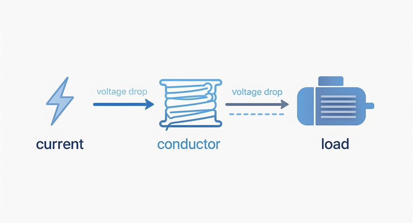
It really drives home that as current travels down a wire to do its job, a loss of voltage is just an unavoidable part of the process.
The More Precise Single-Phase AC Formula
For AC calculations where you need to be spot-on, especially with loads that have a poor power factor, we need to bring out the more advanced formula:
VD = 2 x L x [R x cos(θ) + X x sin(θ)] x I
Okay, don't let this one scare you. Here’s what the new terms mean:
- R is the wire's AC resistance (per 1,000 feet).
- X is the wire's reactance (per 1,000 feet).
- cos(θ) is simply the power factor of the load.
- sin(θ) is the reactive factor of the load.
You don't have to guess these values; you can find R and X in tables right in the NEC, specifically in Chapter 9 (Table 8 and Table 9). While the formula looks a bit intimidating, it’s just accounting for more of the physics happening inside the wire.
Key Takeaway: The simple DC formula is fantastic for quick checks and basic circuits. But for any circuit with motors, transformers, or long runs where precision matters, the detailed AC formula is what the pros use.
This drive for accuracy isn't a new trend. The formulas we use have been fine-tuned over decades to meet real-world engineering demands. The basic formula is really just an adaptation of Ohm’s law, expanded to VD = 2 × I × R × L to account for the total length of the circuit path. This approach helps engineers and electricians keep voltage drop under the widely accepted 3-5% limit, a core principle baked into standards like the NEC to keep installations safe and efficient. For a deeper dive, the folks at Electrical Engineering Portal have some great resources on these calculation methods.
Mastering Calculations for Three-Phase Systems
While single-phase power keeps the lights on at home, three-phase power is the undisputed workhorse of the commercial and industrial world. It's the force behind heavy machinery, massive motors, and complex equipment. But this step up in power brings a slight, but critical, twist to our voltage drop formula.
Three-phase systems are a different beast altogether. Instead of one wave of alternating current, you have three separate currents, each out of sync with the others. This interaction delivers a much smoother, more consistent flow of power, which is ideal for big motors and efficient long-distance transmission.
Because the physics are different, we can't just recycle the single-phase formula. We need an equation that accounts for how these three phases work together.
The Go-To Three-Phase Voltage Drop Formula
For nearly every real-world, three-phase circuit you'll encounter, the formula is a simple tweak on the one we already know. It’s clean, reliable, and gets the job done.
Here’s the standard formula for three-phase voltage drop:
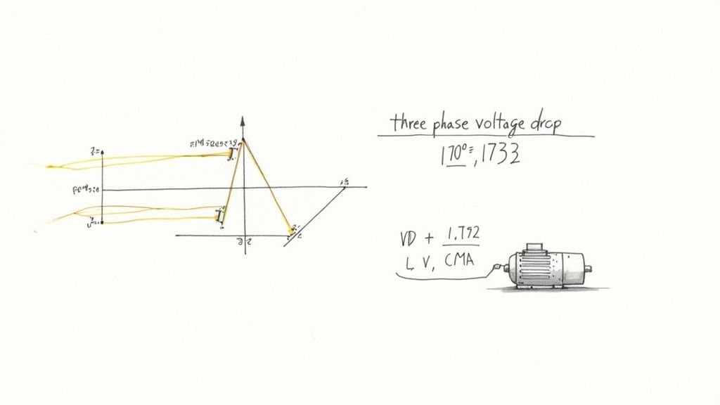
VD = (1.732 x K x I x L) / CMA
Look familiar? It's almost identical to the single-phase version, but we've swapped out the number 2 for 1.732.
What's with 1.732?
That number isn't just pulled out of thin air—it’s the square root of 3 (√3 ≈ 1.732). In a balanced three-phase system, this value mathematically bridges the gap between the voltage on a single phase and the line-to-line voltage, keeping our calculations accurate.
Putting the Three-Phase Formula to Work
Let's run through a common job site scenario. You’re wiring up a 480V, three-phase motor for a conveyor system in a factory. The motor sits 300 feet from the control panel and pulls 25 amps at full load. You've decided to use 8 AWG copper wire, which has a CMA of 16,510.
Time to plug those numbers into our formula.
-
Line up your variables:
- 1.732: Our three-phase constant.
- K: 12.9 (the K-factor for copper).
- I: 25 Amps (the load current).
- L: 300 feet (the one-way distance).
- CMA: 16,510 (for 8 AWG wire).
-
Do the math:
- VD = (1.732 x 12.9 x 25 x 300) / 16,510
- VD = 167,058 / 16,510
- VD ≈ 10.12 Volts
The calculation shows we can expect to lose about 10.12 volts on the way to the motor.
Is This Voltage Drop Acceptable?
Now for the final, crucial step: putting that number in context. Is a 10.12V drop on a 480V system a big deal? We find out by calculating the percentage drop.
- Percentage Drop = (Voltage Drop / Source Voltage) x 100
- Percentage Drop = (10.12V / 480V) x 100
- Percentage Drop ≈ 2.1%
At 2.1%, we are comfortably under the 3% limit the NEC recommends for a single branch circuit. Our 8 AWG wire is the right choice for the job, ensuring the motor gets the voltage it needs to run efficiently without overheating or failing down the line.
When you're designing commercial EV charging solutions, getting these three-phase calculations right is absolutely essential. The high power demands and complex layouts leave no room for error.
This process is critical for any three-phase load, from HVAC units to industrial machinery. Motors are especially sensitive to low voltage; it makes them draw more current, which generates excess heat. For sophisticated setups with Variable Frequency Drives (VFDs), clean and stable power is non-negotiable. Running this simple calculation can prevent costly equipment damage and keep the whole system reliable.
Navigating NEC Rules for Voltage Drop
Knowing how to crunch the numbers with voltage drop formulas is only half the battle. The other half is understanding the industry standards that tell you what’s actually acceptable in the field. For anyone working in the United States, that guidance comes straight from the National Electrical Code (NEC).
The NEC is the bible for safe electrical design and installation. While most of the code is full of hard-and-fast rules you have to follow, its take on voltage drop is a little different. The recommendations show up in what the NEC calls "Informational Notes."
Technically, these notes aren't enforceable laws. But in the real world? They're treated as gospel by professionals. Ignoring them is a recipe for designing an inefficient, problematic, or even unsafe system.
The 3% and 5% Rules of Thumb
The most critical recommendations are boiled down to two simple percentages. These are the guidelines that electricians and engineers live by to ensure every installation is a quality one.
-
NEC 210.19(A) Informational Note No. 4: This note advises keeping the voltage drop on a single branch circuit to 3% or less. This is the run from the breaker in the panel out to the farthest outlet or light fixture.
-
NEC 215.2(A)(1) Informational Note No. 2: This one looks at the bigger picture. It recommends the total voltage drop—across the feeder wires and the branch circuit combined—should not exceed 5%.
Think of it like this: the 3% rule is there to protect the individual appliance or piece of equipment plugged in at the end of the line. The 5% rule protects the health of the entire electrical system, all the way from the main service to that last plug.
If you’re dealing with more complex distribution systems, knowing how feeders and branch circuits are laid out is crucial. You can dive deeper into specific setups in our guide to the NEC tap rule.
To put it all together, here is a quick reference table for the NEC's recommendations.
NEC Recommended Voltage Drop Limits
This table summarizes the key guidelines from the NEC Informational Notes, providing a clear reference for designing efficient and reliable circuits.
| Circuit Type | Recommended Maximum Voltage Drop (%) | NEC Reference |
|---|---|---|
| Branch Circuit Only | 3% | 210.19(A) Informational Note No. 4 |
| Feeder + Branch Circuit Combined | 5% | 215.2(A)(1) Informational Note No. 2 |
Sticking to these limits isn't just about following the code; it’s about good engineering that pays off in the long run.
By sticking to these percentages, you're proactively protecting sensitive electronics, helping motors run cooler and last longer, and preventing the kind of sneaky energy waste that inflates a power bill. It’s a best practice that separates truly professional work from the rest.
Why These Percentages Matter More Than Ever
In today's world, these guidelines aren't just suggestions—they're critical. We're plugging in more high-draw, sensitive electronics than ever before, and there’s simply no room for sloppy voltage. A drop that might have just dimmed an old incandescent bulb can cause serious headaches for modern tech.
Take Electric Vehicle (EV) chargers, for example. An EV charger running on low voltage will charge the car slower and waste electricity in the process. Or think about solar power systems. Every bit of voltage lost between the panels and the inverter is power you can't sell back or use, directly hitting the system's return on investment.
This isn't just a local problem. Energy losses from voltage drop are a huge source of grid inefficiency, with some estimates suggesting that 5-7% of all electricity generated is lost before it's ever used. It’s why in critical DC systems, like commercial solar arrays, designers have long followed an even stricter 2% voltage drop limit to squeeze every last watt out of the system.
At the end of the day, treating the NEC's informational notes as hard requirements is the mark of a true professional. It shows you’re committed to building systems that are not just functional, but efficient, safe, and reliable for years to come.
Avoiding Common Calculation Mistakes
Even the most seasoned pros can get tripped up by simple mistakes when running a voltage drop calculation. It happens. A misplaced decimal point or a forgotten variable can domino into undersized wires, failed inspections, and equipment that just won't perform right.
Getting the math right from the start is non-negotiable. The best way to do that is to know where the common pitfalls are. Think of this as your pre-flight checklist—a quick run-through to make sure your design is built on a solid, accurate foundation.
Forgetting the Round Trip
This one is probably the most common mistake in the book: using the one-way wire length and forgetting that electricity has to make a return trip. It needs a complete circuit to flow, from the source, out to the load, and all the way back again.
Thankfully, most standard voltage drop formulas for single-phase circuits are designed to handle this for you. They already include a multiplier of 2. Where people get into trouble is by either forgetting this or manually doubling the length again in a formula that already does it. That'll throw your results off by a factor of two, leading to some seriously oversized (and expensive) wire.
Rule of thumb: Always use the simple one-way distance for the Length (L) variable in your formula. Trust the formula to handle the round-trip math. For three-phase systems, the 1.732 constant does something similar, accounting for the system's physics.
Ignoring Temperature and Conductor Type
A wire isn't just a wire; its properties change with its environment and what it's made of. Two key details often get missed:
- Ambient Temperature: Resistance goes up as things get hotter. A wire snaked through a blistering hot attic or bundled in a crowded conduit will have a higher voltage drop than one sitting in a cool, open-air environment. You have to apply the right temperature correction factors from the NEC when conditions call for it.
- Wrong 'K' Factor: The resistivity constant, known as the 'K' factor, is completely different for copper (12.9) and aluminum (21.2). If you accidentally plug in the copper value for an aluminum run, your calculation will show a much lower voltage drop than what you'll get in reality. That's a classic recipe for an undersized wire.
Misinterpreting AC Circuit Factors
Alternating current brings a few more variables into the mix that you just don't see in DC circuits. The biggest one people forget is power factor, especially on circuits with motors or other inductive loads. A low power factor means the circuit has to draw more total current to do the same amount of work, and more current means more voltage drop.
For short, simple AC runs, you can often get away with the basic formula as a decent estimate. But for longer distances or circuits feeding motors and other inductive loads, you really need to use the more detailed formula that includes impedance (both resistance and reactance). It's the only way to get precise, reliable results every single time.
Got Questions? We've Got Answers
Even after you've run the numbers, a few practical questions always seem to pop up. Let's tackle some of the most common ones we hear from folks in the field to clear up any lingering confusion.
How Much Voltage Drop Is Too Much?
While the NEC gives us guidance in informational notes, the industry has pretty firm best practices. Sticking to these isn't just about following rules—it's the hallmark of a quality installation that keeps equipment running efficiently for the long haul.
Here are the numbers to live by:
- A branch circuit (think panel to the final outlet) should never drop more than 3%.
- The total system, adding the feeder and the branch circuit together, shouldn't exceed a combined 5% drop.
Pushing past these limits is asking for trouble. You'll see poor performance, wires getting warmer than they should, and you could even shorten the life of the equipment you're trying to power.
Why Is the Three-Phase Formula Different?
It really boils down to the physics of how the power gets from point A to point B. In a simple single-phase circuit, the formula uses a multiplier of 2 because it has to account for the current traveling out on one wire and returning on the other—a complete round trip.
But a balanced three-phase system is a different animal. The return currents are essentially carried on the other phase conductors. The math gets a bit more involved, but the bottom line is that you use the square root of 3 (which is roughly 1.732) instead of 2. This number perfectly captures the push-and-pull interaction between the phases.
Simply put, that 1.732 in the three-phase voltage drop calculation formulas isn't just a random number. It’s the precise constant needed to accurately model how a three-phase circuit behaves in the real world.
Does Power Factor Always Matter for AC Circuits?
Good question. The answer is no, not always.
If you're dealing with simple resistive loads—things like old-school incandescent bulbs or basic electric heaters—the power factor is nearly perfect, right around 1.0 (unity). For these circuits, especially on shorter runs, you can often get away with using the simpler DC voltage drop formula for a "good enough" estimate.
However, the moment you start powering inductive loads like motors, transformers, or big banks of fluorescent or LED lights, power factor becomes a huge deal. A low power factor means the circuit has to draw more total current to do the same amount of work, and that extra current jacks up your voltage drop. For those jobs, you absolutely have to use the more detailed AC formula that accounts for both resistance (R) and reactance (X) to get a number you can trust.
At E & I Sales, we provide the motors, controls, and system integration expertise to ensure your designs are efficient and reliable from day one. For help specifying the right components for your next project, visit us at https://eandisales.com.