
Calculating motor torque is the first, and arguably most important, step in sizing a motor for any job. It all comes down to the relationship between a motor's power (horsepower or kilowatts), its rotational speed (RPM), and the twisting force it can actually produce. A solid torque calculation is your best insurance against picking a motor that can't start, run, and stop a load properly, saving you from premature failures and overheating headaches.
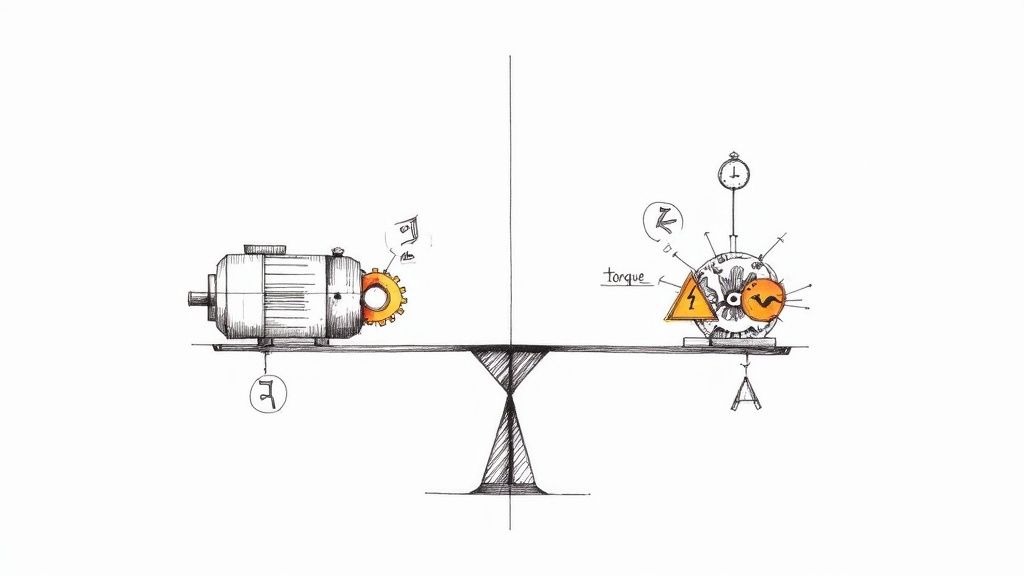
Why Getting Torque Right is Non-Negotiable
Nailing the torque calculation is the bedrock of any reliable mechanical system. We're not just trying to make something move; we're trying to make it move correctly, efficiently, and safely for years to come. Get this wrong, and you're setting yourself up for a domino effect of expensive and potentially dangerous problems down the line.
I always tell people to think of it like picking an engine for a truck. You wouldn't put a four-cylinder sedan engine in a semi-trailer and expect it to haul a full load. It would constantly struggle, redline, and burn out in no time. The reverse is also true—putting a massive diesel engine in a compact car is a colossal waste of money, space, and fuel. The exact same logic applies to industrial motors.
The Real-World Consequences of a Bad Calculation
When you misjudge the torque, the fallout is swift and significant. Undersizing a motor is a classic mistake that leads to constant stalling, overheating, and a drastically shortened service life as the motor strains against a load it was never meant to handle.
On the other hand, oversizing might seem like the "safe" option, but it creates its own set of problems:
- Wasted Energy: An oversized motor runs well below its peak efficiency, which means you're paying for electricity that's just getting turned into waste heat.
- Increased Wear and Tear: The powerful starting torque of a bigger-than-needed motor can slam gearboxes, couplings, and other machinery, causing premature wear.
- Higher Upfront Costs: It’s simple—bigger motors and the beefier controls they require cost more. That’s money straight out of your project budget for no tangible benefit.
Not All Torque is Created Equal
To do a proper torque calculation for a motor, you have to recognize that a motor's job changes from one second to the next. The demands aren't constant, so you need to account for the different phases of its work cycle.
Pro Tip: Look at the entire duty cycle, not just the continuous running phase. I've seen countless motors fail because the engineer only calculated for steady-state operation and completely ignored the massive peak torque needed to get the load moving from a dead stop.
You really need to get familiar with three specific types of torque:
- Starting Torque: You might hear this called "locked-rotor torque." It's the brute force the motor can generate from a standstill. This number has to be high enough to overcome inertia and static friction to get things going.
- Full-Load Torque: This is the workhorse spec—the continuous torque the motor can deliver at its rated speed without breaking a sweat (or overheating). It’s what you’ll be looking at for normal, day-in-day-out operation.
- Breakdown Torque: Sometimes called "pull-out torque," this is the absolute maximum a motor can dish out for a brief moment before it stalls and the speed plummets. It’s a great indicator of how well the motor can handle a sudden, temporary overload.
Once you have a handle on these distinctions, your calculations will start to reflect the true demands of your system, leading to a much more reliable design.
The Core Formulas for Motor Torque
At the end of the day, every motor selection comes down to a handful of essential equations. This is where we stop talking theory and start getting practical, turning a motor’s power and speed ratings into the actual twisting force it can deliver. Getting these formulas right is non-negotiable for sizing a motor that won't let you down.
The main relationship connects torque directly to power and rotational speed. A classic mistake, however, is mixing up your units. A formula built for kilowatts and RPM will give you a useless number if you plug in horsepower. Let's break down the formulas for both Metric and Imperial systems to make sure that never happens.
Calculating Torque from Power and Speed
This is your go-to method for figuring out a motor's full-load torque. You’ll find the power and speed right on the motor's nameplate, making this calculation as straightforward as it gets.
The Metric Formula (Nm)
If you're working in metric, you're using kilowatts (kW) for power and revolutions per minute (RPM) for speed. The result is torque in Newton-meters (Nm), the standard in the SI system.
Here’s the formula:
Torque (Nm) = Power (kW) × 9550 / Speed (RPM)
That magic number, 9550, is a constant that does all the heavy lifting on unit conversions (from kW to watts, and RPM to radians per second). It's a massive shortcut that saves you from having to do that tedious math every single time.
A Lesson from the Field: I once troubleshot a conveyor system that kept stalling. The initial math seemed correct, but the engineer had accidentally used the metric power value (kW) with an imperial formula constant. It was a tiny slip-up, but it resulted in a motor that was nearly 30% underpowered for the application.
The Imperial Formula (lb-ft)
For those of us working with Imperial units, the inputs are horsepower (hp) and speed in RPM. Your torque output will be in pound-feet (lb-ft), which is common across North American industrial equipment.
The formula looks like this:
Torque (lb-ft) = Power (hp) × 5252 / Speed (RPM)
Just like its metric counterpart, the constant 5252 is the key. It neatly reconciles the different units of horsepower, RPM, and pound-feet so the math just works. For a deeper dive into motor sizing, you can find some great information from industry suppliers like E & I Sales.
Common Torque Calculation Formulas and Unit Conversions
To make things even easier, here’s a quick-reference table. It's a good idea to keep this handy to avoid any mix-ups between unit systems.
| Torque Unit | Power Unit | Speed Unit | Formula |
|---|---|---|---|
| Newton-meter (Nm) | Kilowatt (kW) | RPM | Torque = (Power × 9550) / Speed |
| Pound-foot (lb-ft) | Horsepower (hp) | RPM | Torque = (Power × 5252) / Speed |
| Ounce-inch (oz-in) | Horsepower (hp) | RPM | Torque = (Power × 1,008,384) / Speed |
This table covers the most common scenarios you'll encounter, from small-scale robotics to heavy industrial machinery.
An Alternative: Calculating Torque from Current
While the power-and-speed formula is the gold standard for AC induction motors, there's another important relationship to know, especially if you work with DC motors. For brushed and brushless DC (BLDC) motors, torque is almost perfectly proportional to the current it draws.
This relationship is all about the motor's torque constant, or Kt.
- For DC Motors: This connection is beautifully linear. More current means more torque. Simple.
- For AC Motors: Be careful here. This method is much less reliable for AC motors because their torque is also affected by voltage and power factor, both of which change with the load. Using current alone for an AC motor will only give you a rough ballpark figure.
The formula itself couldn't be simpler:
Torque (Nm) = Current (A) × Kt
The Kt value is the torque constant, usually given in Newton-meters per Amp (Nm/A) right in the motor's datasheet. This formula is a game-changer when you're using a motor controller that regulates current, because it means you can directly control the motor's torque output.
For instance, if a BLDC motor has a Kt of 0.08 Nm/A and you're pushing 10 Amps through it, you can confidently expect it to produce about 0.8 Nm of torque. This direct link is fundamental for precision applications like robotics and CNC machines, but remember to stick with the power-based formula for your standard AC induction motors to get an accurate, reliable result.
Getting Your Hands Dirty: Applying Torque Formulas in the Real World
Theory is one thing, but applying these formulas to messy, real-world machinery is where the rubber really meets the road. The equations give you a starting point, but correctly sizing a motor for an industrial application means digging into the specifics of load types, system friction, and the unique demands of the job.
Let's look at a few common scenarios I’ve run into over the years.
This visual really boils it down to the core relationship we're working with: power and speed are your inputs, and torque is the result.
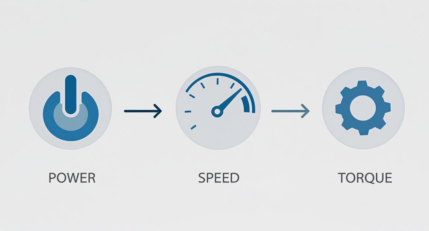
It’s a simple but powerful concept. Everything we do in motor sizing comes back to balancing these three variables to get the performance you need.
Sizing a Motor for a Conveyor Belt
Conveyors are the workhorses of manufacturing and logistics. They're a perfect example of turning a motor's rotation into straight-line motion. The big puzzle here is figuring out how much force it takes to move everything on that belt and overcome all the friction, then translating that back into the rotational torque the motor needs to supply.
Let's say you've got a horizontal conveyor that needs to move 200 kg of product at a steady 0.5 m/s. The drive pulley has a radius of 0.15 meters, and we'll estimate the system's coefficient of friction at 0.05.
First, we need the force required to beat friction.
- Friction Force = Total Mass × g × Coefficient of Friction
- Friction Force = 200 kg × 9.81 m/s² × 0.05 = 98.1 Newtons (N)
That’s the constant pull needed from the belt. Now, let’s see what that means for the motor's drive pulley.
- Torque (Nm) = Force (N) × Radius (m)
- Torque (Nm) = 98.1 N × 0.15 m = 14.72 Nm
So, 14.72 Nm is our baseline torque just to keep the fully loaded belt rolling. But that's in a perfect world, and industrial equipment is anything but.
Don't Forget System Inefficiencies
Every mechanical system has losses. Nothing is 100% efficient. You lose a little bit of energy in the gearbox, in the bearings, and even from the belt stretching. I usually start by assuming an efficiency of about 85% for a standard gearbox and belt drive. It's a safe, real-world number.
To get the actual torque the motor needs to deliver, you have to account for these losses.
- Required Motor Torque = Load Torque / System Efficiency
- Required Motor Torque = 14.72 Nm / 0.85 = 17.32 Nm
There's our number. The motor you choose must be able to comfortably provide 17.32 Nm of continuous torque. If you want to dive deeper into this part of the process, our collection of articles on motor sizing techniques is a great resource.
Calculating Torque for a Centrifugal Pump
Pumps are a whole different animal. Unlike a conveyor with its relatively steady load, a centrifugal pump's torque requirement is deeply tied to its speed. The faster it spins, the exponentially harder the motor has to work. We call this a "variable torque" load.
Imagine we're selecting a motor for a pump that needs 15 kW of power at its target speed of 1750 RPM. Here, the calculation is refreshingly straightforward.
Let's plug it into the metric formula:
- Torque (Nm) = Power (kW) × 9550 / Speed (RPM)
- Torque (Nm) = 15 kW × 9550 / 1750 RPM = 81.86 Nm
Simple as that. The motor we spec for this job must be able to deliver at least 81.86 Nm continuously at 1750 RPM.
Expert Insight: With pumps and fans, the starting torque is usually quite low. The real challenge is making sure the motor has enough guts to handle the load as it ramps up to full speed. I always make it a point to check the motor's speed-torque curve to ensure it can deliver sufficient torque through the entire acceleration phase, not just at the final operating speed.
Determining Torque for a Robotic Arm
Robotics applications are where torque calculations get really interesting because the loads are constantly changing. The required torque shifts with every move, depending on the arm's position, the weight it's lifting, and how fast it needs to accelerate. Your job is to find the peak torque required for the absolute worst-case scenario.
Picture a single joint on a robotic arm holding a 5 kg payload at the end of a 0.8-meter arm segment, stretched out horizontally. The motor has to hold not just the payload, but also the weight of the arm itself—we'll say that's 10 kg, with its center of mass 0.4 meters from the joint.
The total holding torque is a sum of the two forces.
- Torque_payload = 5 kg × 9.81 m/s² × 0.8 m = 39.24 Nm
- Torque_arm = 10 kg × 9.81 m/s² × 0.4 m = 39.24 Nm
- Total Static Torque = 39.24 Nm + 39.24 Nm = 78.48 Nm
And remember, that's just the torque needed to hold the arm steady. To get it moving, you need even more. In electric motors, torque is directly proportional to the supply voltage; more voltage equals more torque. For instance, an electric vehicle motor running on 400V might produce 266 Nm. When that's run through a gear ratio of 7.05, the final torque at the wheels becomes a massive 1,875.3 Nm. This interplay between voltage, gearing, and torque is fundamental to modern machine design.
How to Measure Torque and Verify Your Numbers
After you've run the formulas, you've got a solid theoretical number for your motor's required torque. But in the real world of engineering, theory is only half the battle. The crucial next step is to bridge the gap between your calculations and physical reality, making sure your numbers hold up when the rubber meets the road. This is where measurement comes in, giving you the hard data you need for quality control, performance tuning, and troubleshooting.

Calculations can only get you so far. They don't always account for tricky variables like inconsistencies in materials, minor flaws in assembly, or unexpected friction points in the system. Physical measurement is your ground truth—it confirms that the motor you've picked, or the machine you've built, actually performs the way you designed it to.
The Right Tools for Torque Measurement
To directly measure the twisting force of a motor, you need specialized instruments. The two workhorses for this job are dynamometers and dedicated torque sensors, and each has a specific role to play.
- Dynamometers: Often just called a "dyno," this is a complete testing system. It doesn't just measure torque; it also measures speed, which allows you to map out the motor's full power output across its entire operating range. A dyno applies a controlled load to the motor, making it the perfect tool for creating detailed performance curves.
- Torque Sensors: These are more focused tools designed to measure torque directly. You can install them inline between the motor and the load in a real application, giving you a live feed of how much torque is actually being demanded during a machine's cycle.
When it comes time to check your calculated torque numbers, these physical measurement tools are absolutely essential. To get a better feel for the equipment, it's worth understanding how a dynamometer works and the principles behind it.
How Modern Torque Sensors Work
Most modern torque sensors are built on a brilliantly simple concept: the strain gauge. This technology is the bedrock of industrial measurement. Back in 1938, Professor A.C. Ruge developed the first one, and by 1952, the foil strain gauges we still use today became the standard. Modern sensors based on this principle can achieve impressive accuracies, often within 0.1% to 0.5% of their full scale.
So how does it work? A strain gauge is basically a flexible resistor that's bonded directly to the motor's shaft. When torque is applied, the shaft twists ever so slightly, which stretches or compresses the gauge. This tiny physical change alters its electrical resistance. That change can be measured with incredible precision and converted into a torque value.
There are two main flavors of torque sensors built on this principle:
- Reaction Torque Sensors: These are for measuring stationary torque. They're perfect for jobs like checking the tightening torque on a bolt or measuring the force needed to hold a robotic arm in a fixed position.
- Rotary Torque Sensors: As the name implies, these are designed to measure torque on a spinning shaft. They use slip rings or wireless telemetry to send the signal from the rotating sensor to a stationary receiver, making them indispensable for testing motors while they're running.
Setting Up a Practical Test Rig
You don't always need a million-dollar lab to verify your torque calculations. A well-designed test rig can get you the data you need without breaking the bank.
A Tip from the Trenches: Always start with a rigid, securely mounted base. I've seen countless tests ruined because the motor or sensor was mounted on a flimsy workbench. Any vibration or flexing in your setup will introduce noise and errors into your measurements, making them worthless.
Here's a straightforward approach to building a reliable test rig:
- Mount the Motor Securely: Bolt the motor down to a heavy, stable plate. Make sure it absolutely cannot move or vibrate, even under maximum load.
- Couple the Sensor: Connect your rotary torque sensor to the motor shaft with a high-quality, zero-backlash coupling. Misalignment is the enemy of accurate measurement, so take your time here.
- Apply a Load: Connect the other end of the sensor to a load. For smaller motors, a simple friction brake might do the trick. For larger systems, you'll want a more sophisticated dynamometer or braking system.
- Collect the Data: Use a data acquisition (DAQ) system to record the output from the torque sensor and a tachometer to log the speed simultaneously.
With this setup, you can run the motor through its expected operating conditions and see how the real-world torque lines up with your calculations. If the numbers match, you can move forward with confidence. If they don't, you now have the data you need to figure out what's wrong—whether it's an unexpected source of friction or an issue with one of the many https://eandisales.com/products/electric-motors/ available.
Advanced Considerations for Motor Selection
Getting the basic torque calculation right is a great start, but experienced engineers know that's just the baseline. The real-world isn't a clean, predictable lab environment. To design a machine that lasts, you have to account for the unexpected stresses and strains of daily operation. This is where you move from a good motor selection to a great one.
A critical piece of this puzzle is the service factor. Think of it as an engineering safety net—a multiplier you apply to your calculated torque to build in a buffer for the harsh realities of an industrial setting. It’s what ensures your system doesn't just work on paper but survives in the field.
For instance, a motor driving a fan with a smooth, continuous load might get by with a service factor of 1.0 or 1.1. But if that motor is powering a rock crusher, which gets hammered with shock loads all day, you'll need a service factor of 1.5 or more to prevent a premature burnout.
Applying Service Factors Correctly
Picking the right service factor is part art, part science. It demands a hard look at the actual conditions the motor will face. You have to think about what's going to stress the motor and drivetrain beyond the simple, calculated load.
- Load Type: Is the load steady, or does it hit hard? Things like reciprocating compressors or punch presses are brutal on motors and demand a higher service factor.
- Duty Cycle: How often are you starting and stopping? Any application with more than 10 starts per hour puts a lot of thermal stress on the windings from the repeated inrush current, warranting a higher factor.
- Operating Environment: High ambient temperatures, a ton of dust, or high altitudes all hinder a motor's ability to cool itself. This effectively lowers its performance and means you need to build in a bigger safety margin.
I once saw a conveyor system that kept failing. The engineer had calculated the basic running torque perfectly but completely missed the fact that it was in a dusty warehouse and was started and stopped constantly. A simple 1.25 service factor would have pointed to a tougher motor and saved the company months of downtime.
It's not just the motor, either. The entire powertrain needs to be up to the task. Knowing how to enhance transmission performance and durability with aftermarket parts is crucial, as a stronger motor will just find the next weakest link if the rest of the system can't keep up.
Computational Methods and Dynamic Loads
For complex machinery with constantly changing loads, like robotics or CNC machines, a single torque number just won’t cut it. This is where you need to go beyond static calculations and use modern computational models. These tools let you simulate the motor’s performance through its entire work cycle, not just at one peak moment.
This approach gives you a much clearer picture of the torque calculation for a motor, especially with variable loads. For example, you can model how adjusting the frequency in an AC motor setup will affect its performance under different conditions. Our guide on AC motor variable speed dives deeper into this topic.
The accuracy you can get with these methods is impressive. Research models that account for things like time delays and other non-linear variables have shown torque estimation accuracies above 95%. This level of precision is exactly what's needed to design the highly efficient and responsive automated systems we rely on today.
By embracing these advanced steps—applying the right service factors and using dynamic modeling for complex loads—you stop just picking a motor and start engineering a truly resilient machine.
Frequently Asked Questions About Motor Torque
Even when you've got the formulas down, some practical questions always seem to surface during the motor selection process. That's completely normal—the real world rarely fits perfectly into a neat equation. Let's walk through a few of the most common hurdles to clear up any confusion so you can choose your next motor with total confidence.
Starting Torque vs. Full-Load Torque
People often mix these two up, but they describe two totally different, and equally critical, phases of motor operation.
Starting torque, which you might also hear called locked-rotor torque, is the raw, brute force a motor can generate from a complete standstill (0 RPM). This is the initial muscle needed to overcome the system's inertia and static friction just to get things moving.
Full-load torque, on the other hand, is the steady, continuous twisting force the motor provides when it's humming along at its rated speed and power. This is the "workhorse" spec that tells you if the motor can handle the job long-term without overheating or giving up.
Here's a classic mistake I see all the time: choosing a motor with enough full-load torque but not nearly enough starting torque. The motor might be perfectly capable of running the load once it's up to speed, but it will never actually get it started. You have to check both specs against what your system demands.
How a Gearbox Changes Everything
A gearbox is a game-changer in mechanical design, and it completely alters your torque calculations. Think of it as a torque multiplier—it trades speed for more force. The gear ratio is the key.
For instance, a gearbox with a 10:1 ratio cuts the output speed to just one-tenth of the motor's speed. But in return, it boosts the available torque by a factor of 10, minus a little bit lost to friction inside the gearbox itself (efficiency losses are usually between 5-15%).
So, when a gearbox is in the picture, you have to work your torque calculation for the motor in reverse:
- First, figure out the final torque you need at the load itself.
- Next, divide that load torque by the gear ratio.
- Finally, account for the efficiency loss by dividing that result by the gearbox's efficiency rating (e.g., divide by 0.90 if it's 90% efficient).
The number you're left with is the actual torque the motor needs to produce.
Can I Figure Out AC Motor Torque From Current?
I get this question a lot, and the answer is a hard "it's complicated." With a DC motor, torque and current have a nice, direct, linear relationship defined by its Kt (torque constant). But that's just not the case for AC induction motors.
An AC motor's torque is the result of a complex dance between current, voltage, efficiency, and—the real kicker—the power factor. The power factor isn't a fixed value; it changes dynamically as the motor's load changes.
Because of this, just clamping an ammeter on an AC motor won't give you an accurate torque reading. For reliable and precise results, you really need to stick to the proven formulas that use power (kW or hp) and speed (RPM). It's better to think of amperage on an AC motor as a health indicator or a rough gauge of its workload, not as a direct input for calculating exact torque.
At E & I Sales, we live and breathe this stuff. We specialize in helping engineers and system integrators select the right motor and control solutions for tough industrial jobs. Our experts can walk you through everything from the first calculation to the final commissioning. Discover how our deep product knowledge and system integration services can make your next project a success at https://eandisales.com.