
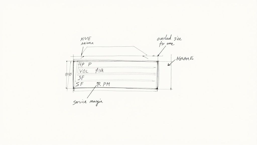
Before you even think about touching a wire, stop and look at the motor's nameplate. This little metal tag is your blueprint for a safe and successful hookup, and it's the foundation for any accurate three phase motor wiring diagram. Honestly, getting this part right is non-negotiable for any tech who wants a motor to run reliably for years to come.
Unlocking the Secrets on a Motor Nameplate
I can't tell you how many times I've seen a motor fail prematurely because someone misread the nameplate. It's not a small mistake—it’s a direct path to fried windings, tripped breakers, and genuinely hazardous conditions. That plate is packed with critical data that dictates everything from your overload settings to whether the motor is even right for the job. It's the most reliable source of truth you have, far more trustworthy than a generic schematic you find online.
A lot of guys will just glance at the horsepower (HP) and voltage and call it a day. While those are obviously important, they're just the start of the story. The real details that prevent callbacks and keep things safe are buried in the other specs.
Key Data Points You Cannot Ignore
When you're inspecting that nameplate, zero in on these values. Each one plays a specific role in how you'll wire and protect the motor.
- Voltage (VOLTS): This tells you the design voltage(s). You'll often see dual-voltage motors, like those marked 230/460V, which need a specific wiring configuration for each. Hooking up a motor wired for 230V to a 460V supply will instantly let the smoke out. It's a fatal mistake.
- Full-Load Amps (FLA or AMPS): This is what the motor will draw when it's working at its rated horsepower. This number is absolutely critical. You use the FLA—not the horsepower—to size your overload protection.
- Service Factor (SF): A service factor of 1.15 means the motor can handle a 15% overload for short periods without damage. If you see an SF of 1.0, it has zero built-in safety margin and you should never push it past its rated HP.
- NEMA Design Letter: This letter (usually B, C, or D) gives you huge clues about the motor's torque characteristics. A Design B motor is your standard workhorse. A Design C gives you higher starting torque, perfect for something like a loaded conveyor. Knowing the difference is key, and if you really want to get into the weeds, you can learn more about torque calculation for motor applications to perfectly match a motor to its load.
A classic field mistake is setting thermal overloads based on a generic horsepower chart. Don't do it. Always use the specific FLA printed on the nameplate. Using a chart can lead to nuisance tripping if the motor's actual draw is higher, or worse, a complete failure to protect the motor if it's lower. The nameplate never lies.
Applying Nameplate Data in a Real Scenario
Let's say you're swapping out a motor on a packaging conveyor. The old one was a 10 HP, 460V motor. The new one you're putting in has the same specs on the box. But when you check the nameplate, you see the new motor has a lower FLA of 12 amps, while the old one was rated for 14 amps.
If you just hook it up without adjusting the overload relay in the starter, you've left that new motor completely unprotected. The relay is still set for the old motor and won't trip until the current hits a point that's already cooking the new motor's windings, drastically cutting its lifespan short.
One more thing: look for a wiring diagram number printed on the plate. This points to the exact connection scheme for the motor's leads (for high vs. low voltage, for example). The diagram is usually on a sticker inside the terminal box cover, but if that's missing or ruined, the nameplate is your permanent backup. That diagram is the heart of your plan.
Choosing Between Wye and Delta Wiring
When you're staring at a three-phase motor's wiring diagram, the choice between a Wye and Delta connection is one of those fundamental decisions that has massive real-world consequences. This isn't just theory; it directly impacts your motor’s starting torque and whether it will even work with your plant's supply voltage.
Getting this right is what separates a technician who just follows a diagram from an engineer who truly understands and optimizes the system.
Pop open the motor's terminal box—often called the peckerhead—and the number of leads you find tells a story. You could see 3, 6, 9, or even 12 leads. This isn't arbitrary. Each count unlocks different wiring options, dictating how the internal windings are grouped and which voltages the motor can handle.
This built-in flexibility is a huge win for everyone. Manufacturers can produce dual-voltage motors that can be adapted in the field, which simplifies inventory and makes them useful across the globe. All it takes is reconfiguring how you connect the leads. For a deeper dive, check out these standard three-phase connections to see the common setups.
Wye Connection: The High-Voltage Workhorse
A Wye connection, also called a "Star" connection because of how it looks on a schematic, is your go-to for higher voltage applications. On a dual-voltage 230/460V motor, for instance, you'd wire it in Wye to run on your 460V supply.
In a Wye setup, one end of each of the three windings is tied together at a common neutral point. The other ends are then connected to your incoming L1, L2, and L3 power lines. This clever arrangement means each individual winding sees a lower voltage—specifically, the line voltage divided by the square root of 3 (about 1.732).
This lower voltage across each winding gives you some distinct advantages:
- Lower Starting Current: This is a big one. It reduces that initial electrical jolt on your system when the motor kicks on.
- Smoother Starts: The resulting lower starting torque is much gentler on connected machinery, making it ideal for equipment like fans and centrifugal pumps.
- A Natural Neutral Point: This can be handy for certain control circuits or monitoring systems that need a neutral reference.
The core principle of Wye wiring is voltage management. By effectively putting the windings in series, you increase their impedance, allowing the motor to run safely on a higher supply voltage without burning up. Get this wrong, and you're looking at catastrophic winding damage.
Delta Connection: The Torque King
When you need raw power, you turn to the Delta connection. This setup is built to deliver the high starting torque required to get heavy loads moving—think fully loaded conveyors, big air compressors, or positive displacement pumps. For that same 230/460V motor, you'd wire it in Delta to run on the lower 230V supply.
In a Delta configuration, the windings are connected end-to-end, forming a closed triangle that looks like the Greek letter delta (Δ). Each corner of the triangle is then fed by one of the three power phases. In this arrangement, every winding gets the full line voltage, which is why it's the choice for the lower of the two voltage ratings.
Here's what you get with Delta wiring:
- High Starting Torque: With full line voltage hitting each winding, the motor produces maximum grunt right from the get-go.
- Higher Starting Current: All that torque comes at a price. The inrush current can be massive, sometimes 5 to 7 times the motor's full-load amp (FLA) rating.
- No Neutral Point: The closed-loop design means there's no common neutral connection available.
That higher current draw in Delta can sometimes cause headaches, especially over long cable runs. If you're pushing the distance, you'll want to review some voltage drop calculation formulas to make sure your motor isn't being starved for voltage when it's under load.
Wye vs. Delta Connection At a Glance
Here’s a quick table to help you keep the two configurations straight. It breaks down the key differences that matter most out on the plant floor.
| Characteristic | Wye (Star) Connection | Delta Connection |
|---|---|---|
| Typical Use Case | Higher voltage operation (e.g., 460V on a 230/460V motor) | Lower voltage operation (e.g., 230V on a 230/460V motor) |
| Starting Torque | Lower, provides a "soft" start | High, for heavy or high-inertia loads |
| Starting Current | Lower, reduces inrush on the power system | Higher, can be 5-7x the Full-Load Amps (FLA) |
| Winding Voltage | Line Voltage / 1.732 | Full Line Voltage |
| Winding Current | Same as Line Current | Line Current / 1.732 |
| Neutral Point | Yes, a common neutral point is created | No, it's a closed-loop configuration |
| Best For | Fans, centrifugal pumps, applications needing a smooth start | Conveyors, compressors, high-torque machinery |
Ultimately, choosing the right connection comes down to matching the motor's capabilities to your supply voltage and the mechanical demands of the load.
Practical Wiring for a 9-Lead Motor
The 9-lead motor is a workhorse in industrial plants precisely because it gives you the flexibility to wire for high or low voltage. Here are the standard NEMA connections you'll use.
Low Voltage (Delta Configuration)
- Tie power line L1 to motor leads T1 and T7.
- Tie power line L2 to motor leads T2 and T8.
- Tie power line L3 to motor leads T3 and T9.
- Connect motor leads T4, T5, and T6 together and cap them off.
High Voltage (Wye Configuration)
- Connect power line L1 to motor lead T1.
- Connect power line L2 to motor lead T2.
- Connect power line L3 to motor lead T3.
- Splice motor leads T4 and T7 together.
- Splice motor leads T5 and T8 together.
- Splice motor leads T6 and T9 together.
A word of caution: always double-check these connections against the diagram on the motor's nameplate or printed inside the peckerhead cover. While these are the NEMA standards, you can still run into variations. Getting it right ensures your motor runs efficiently, delivers the torque you need, and doesn't let out the magic smoke.
Wiring Schematics For Common Motor Starters
Just slapping a three-phase motor on a simple switch and flipping it on is asking for trouble. That initial kick, the inrush current, is massive. It can put a real strain on your whole electrical system and send a nasty mechanical shock down the line to your equipment.
This is exactly why we use motor starters—they give you a controlled, safe way to get things moving. Knowing how to wire them up is a core skill on the plant floor.
You've got options, and each one is a trade-off between cost, complexity, and how much control you get. A basic Direct-On-Line starter is cheap and perfect for little motors. At the other end, a fancy VFD gives you total command but costs a lot more.
Let’s walk through the common setups you'll actually see out there, from the simplest to the most advanced. This diagram gives a great side-by-side of the two core wiring configurations—Wye and Delta—that are the building blocks for most starters.
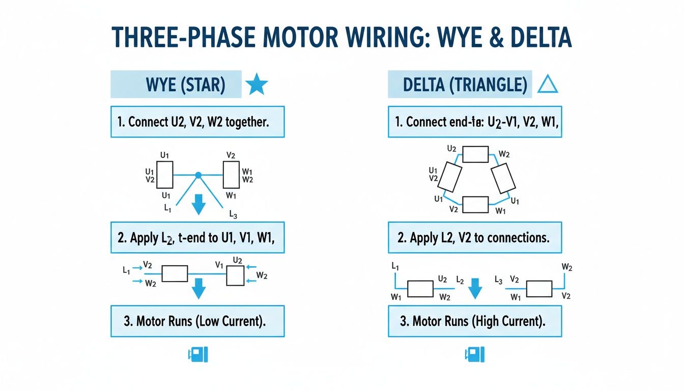
As you can see, the Wye connection creates a central neutral point, which is key for higher voltage setups. Delta, on the other hand, forms a closed loop that delivers more torque at lower voltages. How a starter manages these configurations is what makes each one different.
The Direct-On-Line (DOL) Starter Diagram
This is your bread and butter. The Direct-On-Line (DOL) starter is the go-to for smaller three-phase motors, usually anything under 10 HP. The wiring is refreshingly simple and breaks down into two separate circuits: power and control.
The power circuit does all the heavy lifting. It takes your incoming three-phase power (L1, L2, L3) and runs it straight through a main contactor and an overload relay to the motor terminals (T1, T2, T3). When that contactor slams shut, the motor gets full line voltage instantly.
Then you have the control circuit—the brains of the operation. It typically runs on a lower, safer voltage like 120V AC or 24V DC. Its only job is to energize the contactor's coil. A standard DOL control circuit is made up of:
- A normally closed Stop button.
- A normally open Start button.
- The main contactor coil.
- An auxiliary "holding" contact wired in parallel with the Start button.
- The normally closed contacts from the overload relay.
When you hit "Start," the coil gets juice, the main contactor closes, and the motor runs. That little auxiliary contact also closes, creating a bypass that keeps the coil energized after you let go of the button. To stop it, you either hit the "Stop" button or the overload relay trips, breaking the circuit and dropping out the coil.
The Wye-Delta (Star-Delta) Starter
Once you get into bigger motors, that DOL inrush current becomes a serious problem. The Wye-Delta starter is a classic, effective way to soften the blow. For this to work, you need a dual-voltage motor where all six (or twelve) leads are accessible in the terminal box. The whole idea is to start the motor in a Wye configuration and then switch it over to Delta for the run.
Here's the magic: starting in Wye means the motor windings only see about 58% of the full line voltage. This slashes the starting current and torque down to roughly one-third of a DOL start. It's a much gentler way to get a big motor up to speed.
The wiring is definitely a step up in complexity. You’re juggling three contactors and a timer.
- Main Contactor: Feeds power (L1, L2, L3) to the motor's primary terminals (T1, T2, T3).
- Star Contactor: When it pulls in, it shorts the secondary terminals (T6, T4, T5) together, creating that Wye neutral point.
- Delta Contactor: After the start sequence, this one connects the secondary terminals to the primary ones (T6-T1, T4-T2, T5-T3) to form the Delta connection.
- Timer: This orchestrates the whole dance. You hit "Start," and the Main and Star contactors close. After a few seconds (usually 5-10), the timer kicks out the Star contactor and pulls in the Delta. There's a critical, split-second "off" moment in between to prevent a dead short.
Soft Starters and Variable Frequency Drives (VFDs)
Today, electronic starters give us a level of control the old electromechanical relays could only dream of. And while their internal guts are complex, wiring them up is often surprisingly straightforward.
Wiring a Soft Starter
A soft starter uses solid-state electronics—specifically SCRs (Silicon Controlled Rectifiers)—to gently ramp up the voltage to the motor. The result is a perfectly smooth, stepless start. For a three phase motor wiring diagram using a soft starter, the power wiring is a straight shot:
- Input: Land your incoming L1, L2, and L3 on the starter's input terminals.
- Output: Run wires from the starter's T1, T2, and T3 terminals right to the motor.
- Control: This is just low-voltage wiring for your start/stop signals, which might come from a PLC or a simple set of push buttons.
A lot of modern soft starters also include a bypass contactor. Once the motor is at full speed, this internal contactor closes, taking the electronics out of the circuit. This makes it more efficient and cuts down on heat.
Wiring a Variable Frequency Drive (VFD)
For ultimate motor control, nothing beats a VFD. It lets you fine-tune both speed and torque. Just like a soft starter, the main power connections are simple: L1, L2, L3 in; T1, T2, T3 out to the motor. Where the VFD really shines is in its extensive control wiring possibilities.
A typical VFD setup will include:
- Start/Stop Command: This can be a simple two-wire switch or a three-wire control circuit that mimics a DOL starter.
- Speed Reference: This tells the drive how fast to run. It's usually an analog signal, like a 4-20mA current loop or a 0-10V DC signal, coming from a PLC or a simple speed pot on the control panel.
- Digital Inputs: These are used for all sorts of extra functions—think forward/reverse, jog, or switching between pre-programmed speeds.
VFDs are invaluable in packaging and conveyor applications where you need precise control over acceleration and speed. Deciding between a simple DOL starter and a feature-packed VFD all comes down to what the machine needs to do.
Safe Wiring Practices and Code Compliance
Having the three-phase motor wiring diagram is a great start, but the job isn't done until the installation is safe, secure, and up to code. This isn’t about just passing an inspection; it’s about professional work that protects people from shock, equipment from damage, and your plant from fire.
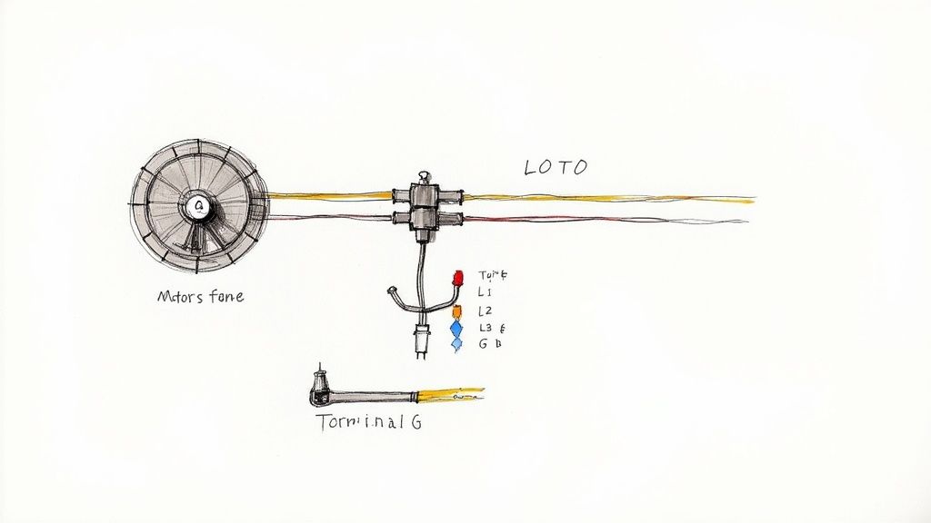
Before you even think about touching a wire, your first step is always Lockout/Tagout (LOTO). This is a hard-and-fast rule, no exceptions. De-energize the circuit, lock out the breaker or disconnect, and make sure you’re the only one holding the key.
Grounding and Conductor Sizing
A solid ground connection is what stands between you and a potentially lethal shock. If a fault occurs, the entire metal frame of the motor can become energized. That’s why you must always connect the green or bare copper ground wire to the grounding lug in the motor’s junction box, ensuring a clean, unbroken path back to the panel.
Next up is choosing the right size wire, or conductor. This isn't a place for guesswork. The wire gauge is determined by the motor's Full-Load Amps (FLA) listed on the nameplate and the rules laid out in the National Electrical Code (NEC). Using a wire that's too small is a recipe for disaster—it’ll overheat, the insulation will melt, and you’ve got a serious fire hazard on your hands.
Think about it this way: a motor with a 25A FLA that's 200 feet from the panel needs a beefier wire than the same motor located just 20 feet away. This is to compensate for voltage drop over distance. The NEC has tables that make this straightforward, helping you select the right conductor based on amperage, material (copper vs. aluminum), and insulation type.
Understanding Conductor Color Codes
Getting your phases mixed up can cause a motor to spin backward, which can be catastrophic for pumps, fans, and conveyors. Consistent color coding is your best tool for preventing this and for making any future troubleshooting much easier.
While you should always check local codes, a widely used standard for 480V three-phase systems in North America is:
- Phase A: Brown
- Phase B: Orange
- Phase C: Yellow
- Ground: Green, Green with a Yellow Stripe, or Bare Copper
For 208/230V systems, you'll more commonly find Black, Red, and Blue. The specific colors are less important than absolute consistency across your facility.
Remember this: Code compliance isn't just a hurdle to clear. It's about building a predictable system. Properly sized fuses and breakers are the designated "weak links"—they are meant to fail first to protect a motor that could cost thousands to replace.
Overload and Short-Circuit Protection
This is a point of confusion for many, but it's critical to get right. Every motor circuit needs two different kinds of protection.
- Short-Circuit Protection: This is your circuit breaker or fuse. Its job is to react instantly to the massive inrush of current from a direct short or ground fault, preventing a fire or explosion. You size these based on NEC tables, not just the motor's FLA.
- Overload Protection: This is usually a thermal overload relay inside the motor starter. It's designed with a time delay to ignore the brief current spike during startup. Its purpose is to protect the motor from sustained, lower-level overcurrents from things like a mechanical jam, which prevents the motor windings from cooking themselves.
Sizing these protective devices correctly is non-negotiable. In some cases, the rules for tapping conductors from a larger feeder can be complex. To do it safely, you need to follow strict guidelines, which you can learn more about by understanding the NEC tap rule.
Finally, don't forget the basics of making a solid physical connection. Use the right size lugs for your wires and torque them down to the manufacturer's spec. A loose connection is a hot connection. It creates resistance, which generates heat—enough to melt terminals and start a fire. A clean, tight, and properly torqued connection is the final step to a safe and reliable motor installation.
Testing and Troubleshooting Your Connections
All your connections are tight, the peckerhead cover is back on, and you’re ready to bring the machine to life. This is the moment of truth. But before you throw that main disconnect, a few quick verification checks will protect the motor and save you from a world of headaches.
Think of it as an engine builder checking the oil before the first startup. Sure, you could skip it and you might get lucky. But the risk of immediate, expensive damage just isn't worth it. Taking a few extra minutes here confirms you've executed the three phase motor wiring diagram perfectly.
Pre-Power-Up Verification Checks
Grab your multimeter. A couple of quick checks before applying power can catch a simple mistake before it becomes a catastrophic failure. These tests are all about confirming the integrity of your work and the motor's internal windings.
- Continuity Check: Flip your meter to the continuity or resistance setting. Check the resistance between each of your phase terminals—T1 to T2, T2 to T3, and T1 to T3. The readings should be very low (just a few ohms) and, more importantly, almost identical across all three pairs. A perfectly balanced reading tells you the windings are good. An open line (infinite resistance) means you’ve got a broken winding or a loose connection somewhere.
- Insulation Resistance Check: Now, grab a megohmmeter (you probably call it a "megger") to hunt for shorts. Test from each phase terminal to the motor's ground lug. You’re looking for a very high resistance reading, deep into the megaohms. This confirms that no windings are shorted to the motor's frame, which could cause a dangerous fault.
A crucial pre-start step is the "bump test." Make sure the motor is uncoupled from the gearbox, pump, or whatever it’s driving. Then, just briefly apply power—literally for a second—and kill it. Watch the shaft or cooling fan. If it's spinning the wrong way for your machine, kill and lock out the power immediately.
Reversing rotation is the easiest fix on the planet. Just swap any two of the three incoming power leads. For instance, swap the wires on L1 and L2. That’s it. This simple change reverses the phase sequence, which flips the direction of the motor's rotating magnetic field.
Common Troubleshooting Scenarios
Even the most seasoned electrician runs into issues. If you know what to look for, the symptoms will point you straight to the problem.
Motor Hums but Won't Start
This is the classic sign of a lost phase. The motor is getting some juice, enough to create a magnetic field that makes it hum, but it doesn't have the complete three-phase power it needs to start turning.
- Check Your Supply: Start at the source. Use a voltmeter to verify you have the correct voltage across all three phases (L1 to L2, L2 to L3, L1 to L3).
- Inspect Fuses & Breakers: A single blown fuse or a tripped pole on a three-pole breaker is a very common culprit.
- Examine Connections: Get your eyes on the wiring. A loose connection at the starter, disconnect, or inside the motor's terminal box can easily cause you to drop a phase.
The smooth, powerful rotation of these motors comes from that nearly constant rotating magnetic field. This design innovation cut torque ripple down to about 15%, a massive leap from older single-phase designs that led to smoother and more productive machinery. You can find more on the history of 3-phase electricity at kathylovesphysics.com.
Overload Trips Immediately on Startup
If the overload relay trips the second you hit the start button, the motor is drawing way too much current. Something is seriously wrong.
- Mechanical Jam: Before you blame the wiring, make sure the motor and its load can actually turn freely. A seized bearing, a jammed conveyor, or a clogged pump will cause an instant overload.
- Incorrect Wiring: Go back and double-check your connections. A common mistake is wiring a dual-voltage motor for low voltage but connecting it to a high-voltage supply. This will create a massive inrush of current and trip the protection instantly.
- Wrong Overload Setting: Check that the amp setting on the overload relay is properly matched to the motor's Full Load Amps (FLA) listed on the nameplate.
Common Questions from the Plant Floor
When you're staring at a three phase motor wiring diagram, a few questions always seem to come up. Whether you're a seasoned engineer or a new tech, getting these right is key to a safe, reliable installation. Let's walk through the ones I hear most often.
What Happens If You Wire a Three Phase Motor Incorrectly?
Getting the wiring wrong can range from a simple fix to a catastrophic failure.
The most common mistake is reversed rotation. If the motor spins the wrong way, don't panic. Just swap any two of the three phase leads—L1 and L2, for example. This flips the phase sequence and gets you spinning in the right direction. Easy.
A much bigger problem is mismatching the voltage. Say you wire a dual-voltage motor for its 230V setting but hook it up to a 460V supply. The result is a massive, almost instant current draw that will fry the windings beyond repair. Always, always double-check your connections against the diagram before you energize.
A word of caution on Wye-Delta starters: one wrong move here can create a dead short circuit between phases the second that timer transitions. This can trigger a dangerous arc flash, trip main breakers, and destroy contactors or the motor itself.
Can You Run a Three Phase Motor on Single Phase Power?
Technically, yes, but you can't just plug it in. You need a converter.
The best and most common way to do it is with a Variable Frequency Drive (VFD). A VFD is smart enough to take a single-phase input and electronically generate a perfectly balanced three-phase output. As a bonus, you get full speed control.
Other options exist, like a rotary phase converter, which uses an idler motor to generate that third leg of power. There are also static phase converters, which are simpler capacitor-based boxes, but be aware they typically cut the motor's horsepower by about a third. This makes them a no-go for heavy-load applications.
How Do You Identify Unmarked 9 Lead Motor Wires?
This is where things get tricky, but a good multimeter is your best friend.
- First, you need to find the three separate winding circuits. Set your meter to continuity and start testing. You should find three distinct groups of three wires that are only connected to each other (for example, T1, T4, and T7 will show continuity, but not with any other wires).
- Now for the hard part: figuring out which wire is which within a circuit (is this T1 or T4?). This requires a more advanced test involving a low DC voltage on one winding while you check for induced voltage and polarity on the others with a sensitive voltmeter. Honestly, this is a job for an experienced motor tech or a rewind shop.
For any motor control needs, from premium electric motors to custom UL-listed control panels, E & I Sales provides the expertise and equipment to ensure your projects are reliable and code-compliant. Find the right solution at https://eandisales.com.