
Three-phase monitoring is like a continuous health check for your most critical industrial equipment. It’s all about spotting electrical issues like voltage imbalances or current spikes before they can cause a catastrophic failure, giving you the hard data needed to prevent costly downtime and protect high-value assets.
What Is Three Phase Monitoring and Why It Matters
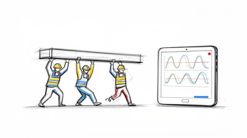
Think about a three-person crew perfectly synchronized, lifting a heavy, expensive piece of machinery. When all three lift with equal force and timing, the load is stable and everything goes smoothly. But what happens if one person stumbles or suddenly loses their grip? The whole operation is at risk. The load becomes unstable, putting immense strain on the other two and risking a disastrous drop.
That’s the perfect way to think about three-phase power. The big motors and pumps that drive your operations depend on three balanced electrical currents—or "phases"—to run efficiently and safely. When those phases are in harmony, your equipment runs like a dream.
The High Cost of an Imbalance
The trouble starts when one phase weakens, surges, or disappears entirely. This condition, known as phase loss or imbalance, has severe and immediate consequences. Your motor is suddenly forced to work much harder under incredible stress, causing it to overheat in a hurry. This kind of thermal stress degrades insulation and can completely destroy windings, leading to a premature and catastrophic failure.
This is why proper three-phase monitoring is so vital for maintaining the health of complex electrical systems. It’s designed to identify these subtle problems long before they escalate into serious equipment damage, acting as an early warning system that gives your team the data they need to step in and fix things.
An unbalanced electrical supply is one of the biggest culprits behind motor failure. Even a small voltage imbalance can dramatically spike a motor's temperature and literally cut its operational lifespan in half, turning a preventable issue into a major capital expense.
Turning Data into Reliability
The real goal of three phase monitoring isn't just about collecting a bunch of data points; it's about turning that data into rock-solid reliability. By keeping a constant watch on the vital signs of your power supply, you can:
- Prevent Unplanned Downtime: Catch phase imbalances, voltage sags, and overcurrent conditions before they trip breakers or burn out motors.
- Extend Equipment Lifespan: Make sure your motors run well within their specified limits, which drastically reduces wear and tear from electrical stress.
- Improve Energy Efficiency: Pinpoint and fix power quality issues that cause equipment to draw more power than needed, helping to lower your operational costs.
In the world of industrial power management, three-phase multifunction monitoring relays are a cornerstone technology. To give you an idea of their importance, the global market for these relays was $1,120.68 million back in 2021 and is projected to climb to $1,438.9 million by 2025. That growth tells you everything you need to know about their vital role in protecting critical assets.
Understanding Your System's Electrical Vitals
To really get a handle on protecting your motors, you need to speak their language. The data from your monitoring system isn't just a bunch of numbers—it's the vital signs of your entire electrical operation. We're going to move past the textbook definitions and get into why each of these metrics is a make-or-break indicator for performance and reliability.
It helps to think of your electrical system like the plumbing in a huge building. The parallels are surprisingly useful and can make some pretty complex electrical ideas click into place. Suddenly, those abstract figures on a screen become real, actionable intelligence.
The Core Duo: Voltage and Current
Let's start with the absolute basics: voltage and current. These two are the foundation of everything else.
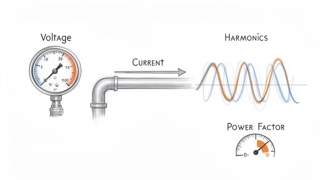
Voltage is your electrical 'pressure.' Just like water pressure is needed to push water through pipes, voltage is the force pushing electrical energy through the wires to your equipment. If that pressure drops too low (undervoltage), your motor will strain to do its job, causing it to overheat and run inefficiently. On the flip side, if the pressure is too high (overvoltage), you risk frying sensitive components and drastically shortening the motor's life.
Current is the 'flow rate.' Measured in amps, it's the amount of electricity your motor is actually pulling to get the work done. A sudden, sharp spike in current is often the first red flag that a motor is struggling with a mechanical problem, like a bearing starting to seize up or a jam on the conveyor line. Watching the current gives you a live look at the motor's real-world workload.
Keeping a close eye on voltage and current is ground zero for any effective three-phase monitoring plan. These two numbers are the starting point for diagnosing nearly every other electrical headache you might encounter on the factory floor.
Imbalance: The Uneven Workload
This is where the 'three' in three-phase power becomes so important. An imbalance happens when the voltage or current isn't perfectly equal across all three phases. Think of it like a three-person team trying to lift something heavy, but one person is slacking off. The other two have to work way harder to pick up the slack, putting a dangerous amount of strain on them.
For a motor, that uneven load is a death sentence. The imbalance creates what are called negative sequence currents, which actively work against the motor's rotation. This generates a massive amount of waste heat, and that thermal stress is one of the biggest killers of winding insulation, leading directly to costly and premature motor burnouts. A solid grasp of motor control circuit design is crucial for understanding how these imbalances wreak havoc.
Harmonics: The Electrical Pollution
Harmonics are a type of electrical 'pollution,' and a common culprit is modern equipment like Variable Frequency Drives (VFDs). VFDs are fantastic for controlling motor speed and saving energy, but they don't draw power in a nice, smooth sine wave. Instead, they chop it up, creating distortion and 'noise' that gets reflected back into your entire electrical system.
This harmonic distortion is especially brutal on motors and transformers, causing them to vibrate and overheat. It's like feeding your equipment electrical junk food; it'll run, but it’s causing serious long-term damage. This is a huge issue in modern plants, where it's not uncommon for 70% of motor drives to be affected by VFD-induced harmonics, making advanced power quality meters an absolute must-have. You can dive deeper into how to improve your overall electrical power quality.
The numbers don't lie. The market for the very three-phase power quality meters needed to fight these issues was on track to hit $1,252 million back in 2021. This explosive growth is a direct answer to the staggering cost of outages, which hit manufacturers for an estimated $50 billion every year.
Power Factor: Your Efficiency Score
Finally, we have the power factor. This metric, scored on a scale from 0 to 1, is basically your system's efficiency report card. It tells you how effectively your equipment is turning the electricity it receives into actual, useful work.
A low power factor (say, 0.75) means your system is pulling more current from the grid than it's actually using, which is just wasted energy. This not only bloats your utility bills but also puts unnecessary stress on your transformers and wiring. In fact, many utility providers will hit you with hefty penalties for a poor power factor, making it a critical number to watch for financial reasons alone. Consistent three phase monitoring is the only way to keep this vital sign healthy.
To tie this all together, here's a quick-reference table breaking down these critical parameters. Think of it as a cheat sheet for diagnosing the health of your three-phase systems at a glance.
Critical Three Phase Monitoring Parameters and Their Impact
| Parameter | What It Measures | Sign of a Problem | Risk of Inaction |
|---|---|---|---|
| Voltage | Electrical 'pressure' in the system. | Sustained levels outside the +/- 10% nominal range (sags or swells). | Equipment damage, overheating, premature failure. |
| Current | Electrical 'flow rate' consumed by the load. | Sudden, unexplained spikes or consistently high readings. | Overheating, insulation breakdown, imminent motor failure. |
| Imbalance | The difference in voltage or current between phases. | A deviation of more than 1-2% between any two phases. | Severe motor overheating, drastically reduced lifespan, burnout. |
| Harmonics | Distortion or 'pollution' on the electrical waveform. | High Total Harmonic Distortion (THD), especially from VFDs. | Overheating of motors/transformers, equipment malfunction. |
| Power Factor | Efficiency of converting power to useful work. | A value consistently below 0.90. | High energy bills, utility penalties, wasted system capacity. |
Understanding what these numbers mean is the first step. By actively monitoring them, you're not just collecting data—you're getting ahead of catastrophic failures, optimizing energy use, and protecting your most valuable assets.
The Hardware You Need for Accurate Monitoring
Knowing what to measure is one thing, but having the right tools for the job is what makes effective three-phase monitoring actually happen. Think of your monitoring system as a small, specialized team. You’ve got the sensors acting as the eyes and ears, the meter as the brain crunching the numbers, and the protective gear that steps in when things get dicey.
Putting this team together correctly is the difference between getting raw data and getting real, actionable intelligence. It's how you spot trouble brewing long before it takes down a critical piece of equipment.
The Eyes and Ears of Your System
First things first: you can't just hook up a multimeter to a 480V industrial circuit. It’s not just impractical; it’s incredibly dangerous. That's where instrument transformers come in. They are the essential sensory organs of your entire setup.
There are two main types you'll be working with:
- Current Transformers (CTs): These are your system's 'ears.' A CT is a ring you simply clamp around one of the main power conductors. It doesn't make any direct electrical contact. Instead, it senses the magnetic field generated by the current and scales it down to a safe, low-level signal that a meter can easily read.
- Potential Transformers (PTs): These are the 'eyes.' A PT (or voltage transformer) is wired in parallel with the high-voltage line. It does for voltage what a CT does for current—stepping it down from something like 480V to a standardized, safe level like 120V for your meter to analyze.
These two components work in tandem to provide a safe, perfectly scaled-down version of the heavy-duty power flowing through your circuits, feeding reliable information to the brain of the operation.
The Brain of the Operation: Power Meters
All that data from the CTs and PTs is just noise without something to make sense of it. That’s the job of the multifunction power meter—the true brain of any modern monitoring system. These aren't just simple readouts; they're powerful little computers that take the raw signals and instantly calculate everything we care about, from basic voltage and current to tricky stuff like power factor and harmonic distortion.
The market for these devices is exploding, projected to hit $15 billion by 2025, which shows just how critical they've become. In industrial motor control centers, where a simple imbalance can be responsible for 25% of all motor failures, these smart meters are non-negotiable. You can dig into the numbers yourself by reading the full market research on this industrial shift.
A multifunction meter is the nerve center of your monitoring strategy. It translates the complex electrical language of your system into clear, understandable metrics you can actually use to make smart decisions.
Protective Relays and Analyzers
If the meter is the brain, then a protective relay is the system's guardian angel. This device goes a step beyond just monitoring—it takes action. You can program a relay to automatically trip a breaker if it sees a dangerous condition, like a massive overcurrent or a complete phase loss. It’s an automated safety net that can shut down a motor before it self-destructs, reacting far faster than any human ever could.
For those really tricky, intermittent electrical gremlins, you might need to bring in the specialist: a power quality analyzer. While your meter gives you the day-to-day vital signs, an analyzer is like an EKG for your electrical system. It can capture high-speed events and perform a deep-dive analysis of harmonic issues, helping you find the root cause of problems that otherwise seem to appear and disappear at random. Whether you need a standard meter or a full-blown analyzer really just depends on how complex your facility is and how deep you need to go.
Integrating Monitoring into Your Control Panels
Having the right hardware is a great start, but a pile of even the best components doesn't automatically create an intelligent system. The real magic happens when you bring it all together. Integration is where you transform individual devices into a single, cohesive network that gives you clear, actionable data.
Think of it as building the central nervous system for your electrical assets, connecting them all back to your main command center.
This process is about more than just plugging things in. It demands careful planning to ensure everything is safe, the signals are clean, and you’re compliant with standards like the National Electrical Code (NEC). When you get it right, data flows seamlessly from your current transformers and meters directly into your PLC or SCADA system, painting a live picture of your entire operation's electrical health on one central dashboard.
This flowchart shows the fundamental journey of data in a three-phase monitoring system—from a raw signal to an intelligent action.
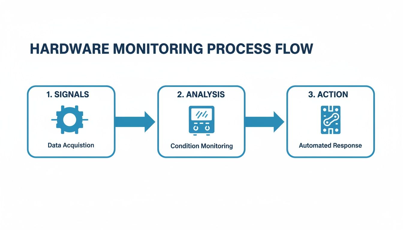
As you can see, it starts with sensors gathering the raw electrical data. That data is then processed by a meter and finally used to trigger a protective or automated response.
Wiring Best Practices for Signal Integrity
Reliable data starts with clean wiring. Industrial environments are electrically noisy places, full of interference from large motors and VFDs. Protecting the low-voltage signals coming from your monitoring hardware is absolutely critical. A corrupted signal can lead to false alarms or, far worse, a missed fault condition that could have been prevented.
To keep your signals clean, stick to these essential best practices:
- Use Shielded Cabling: Always run shielded twisted-pair cables for your communication lines (like Modbus or Ethernet) and for the analog signals from CTs and PTs. This shield is your first line of defense against electromagnetic interference (EMI).
- Proper Grounding: Ground the shield at one end only, usually at the control panel or meter side. If you ground both ends, you can create a ground loop, which actually invites noise onto the line and corrupts the very signal you're trying to protect.
- Separate Power and Signal Wires: This is a big one. Never run your low-voltage signal wiring in the same conduit or wire tray as high-voltage power cables. Keep them as far apart as possible to prevent the powerful magnetic fields from the power lines from bleeding noise into your sensor wiring.
Connecting to Your PLC and SCADA Systems
Once your hardware is properly wired, the next step is talking to your primary control system, whether that's a Programmable Logic Controller (PLC) or a Supervisory Control and Data Acquisition (SCADA) system. This is what unlocks centralized three phase monitoring and historical data logging.
Most modern meters speak the common industrial languages. The ones you’ll run into most often are:
- Modbus RTU: A serial communication protocol that's been the workhorse of industrial automation for decades. It's incredibly reliable and supported by pretty much every PLC and HMI out there.
- Modbus TCP/IP: This is the Ethernet version of Modbus, letting your meters connect directly to the facility's network. It’s faster and gives you more flexibility for tying into modern SCADA systems.
- EtherNet/IP: Another popular Ethernet-based protocol, especially common in plants that lean heavily on Rockwell Automation/Allen-Bradley PLCs.
The goal here is to map the data registers from the meter to the tags in your PLC or SCADA software. This mapping tells the control system where to look for specific data points—like the voltage on Phase A, the total harmonic distortion, or the power factor—so it can be displayed, logged, and used to trigger alarms.
Proper integration isn't just about seeing what's happening right now; it's about creating a historical record. That data lets you track trends over time, figure out what really happened after a trip, and finally shift from reactive repairs to a data-driven, predictive maintenance strategy.
The Role of UL-Listed Control Panels
While you could piece together a monitoring system yourself, that path is loaded with risks related to safety, compliance, and performance. This is where professionally engineered, UL-listed control panels are worth their weight in gold.
A UL listing (like UL508A for industrial control panels) is an independent stamp of approval certifying that the entire panel assembly—not just the individual parts—meets tough safety and construction standards. To really appreciate the work that goes into this, it's worth exploring the principles behind industrial control panel design.
Going with an expertly engineered and certified panel takes the guesswork and risk out of the equation. It guarantees that all components were chosen to work together perfectly, wired according to best practices, and fully tested before they ever show up at your facility. This approach saves a massive amount of time during commissioning and ensures you get reliable, safe performance from day one.
Translating Monitoring Data into Actionable Fixes
All that raw data streaming from your meters? It's just noise until you know how to read it. The real power of three phase monitoring isn't in collecting data—it's in translating those numbers into smart, decisive action.
Think of this as your field guide for turning a blinking light on a screen into a practical fix on the floor. When you understand the story the data is telling, your team can stop reacting to problems and start preventing them, catching small electrical issues before they have a chance to snowball into catastrophic failures.
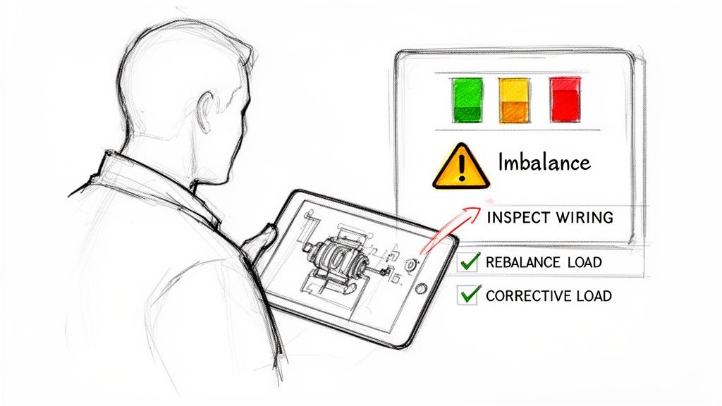
Diagnosing a Persistent Voltage Imbalance
A voltage imbalance alert is one of the most common—and destructive—issues you'll run into. If your system flags a persistent difference of more than 1-2% between phases, that’s a direct warning that your motors are under serious thermal stress.
First things first, you have to find where the problem is coming from. Voltage imbalances usually have one of two sources: an issue inside your facility or a problem with the power coming from the utility.
Here’s how to track it down:
- Isolate the Source: Start at your main service entrance. Check the voltage before it gets to your distribution panels. If the imbalance is already there, the problem is likely on the utility’s end. Time to give them a call.
- Inspect Your Panels: If the power coming in is clean and balanced, the issue is on your side of the meter. The usual suspect? Too many single-phase loads—things like office equipment, lighting, or small heaters—loaded up on one or two phases.
- Balance the Loads: This is a job for an electrician. They can help redistribute those single-phase circuits more evenly across your panels. The goal is to get the current draw on each phase as close to equal as possible, which will bring your voltage back into balance and save your three-phase gear.
Responding to Overcurrent and Overload Alerts
An overcurrent alert means a piece of equipment, usually a motor, is pulling more current than its nameplate rating. This is a critical warning. Sustained overcurrent is the number one cause of motor overheating and burnout. The root cause could be mechanical or electrical.
Start by looking at the nature of the overcurrent. Was it a massive, sudden spike, or has it been creeping up over time?
A sudden trip often points to a mechanical jam, a short circuit, or a ground fault. A slowly rising current, however, typically indicates a developing mechanical issue, like a failing bearing that is forcing the motor to work progressively harder.
This distinction is key. If the current spike was instantaneous, you should be inspecting the driven equipment for a physical jam. If the current has been climbing for a while, the motor itself is the likely culprit and needs a mechanical inspection. This is the kind of insight that builds an effective strategy for predictive maintenance for manufacturing operations.
Tackling Low Power Factor and Harmonics
Alarms for low power factor and high harmonic distortion often go hand-in-hand. A poor power factor (anything below 0.90 is a red flag) means you're wasting energy and probably getting hit with utility penalties. High Total Harmonic Distortion (THD), often created by VFDs, pollutes your electrical system and causes sensitive equipment to overheat.
When these alarms pop up, the fix usually involves power quality correction.
- For Low Power Factor: The most direct fix is to install power factor correction capacitors. Think of them as a local reservoir of reactive power, improving efficiency and reducing the current your facility has to draw from the grid.
- For High Harmonics: If VFDs are creating the electrical noise, installing harmonic filters or line reactors is the solution. These components act like shock absorbers, cleaning up the distortion and protecting everything else on the circuit.
By connecting specific alerts to a logical diagnostic process, your team can act quickly and with confidence. This table is a quick cheat sheet for that initial response.
Common Three Phase Faults and Diagnostic Clues
| Symptom / Alert | Potential Cause | First Diagnostic Step |
|---|---|---|
| Voltage Imbalance | Unevenly distributed single-phase loads; utility supply issue. | Measure voltage at the main service entrance to isolate the source. |
| Overcurrent Trip | Mechanical jam, bearing failure, short circuit. | Check driven equipment for obstructions; analyze current trend data. |
| Low Power Factor | Inductive loads (motors) without correction. | Install power factor correction capacitors at the motor or panel. |
| High Harmonics | Prevalent use of Variable Frequency Drives (VFDs). | Install harmonic filters or line reactors to absorb distortion. |
Having a simple, repeatable process takes the guesswork out of troubleshooting and turns your monitoring system into a true problem-solving tool.
The Financial Case for Three-Phase Monitoring
While the technical perks of three-phase monitoring are obvious to any engineer, the decision to actually write the check often boils down to one simple question: what’s the payback?
A well-planned monitoring strategy isn’t just another line item in the maintenance budget. It's a powerful financial tool that pays for itself, often many times over, by preventing catastrophic costs and finding hidden efficiencies you never knew you had.
The numbers are staggering. Unscheduled downtime in manufacturing costs the industry an estimated $50 billion every year. A huge chunk of that comes from electrical issues that a good monitoring system is built to see coming a mile away. Let's get out of the clouds and look at a couple of real-world situations where this tech delivers a direct, measurable ROI.
From Unplanned Downtime to Scheduled Maintenance
Picture a big manufacturing plant where a single critical conveyor motor is the heart of the main production line. Without monitoring, the first sign of a problem is usually the motor seizing up, bringing everything to a screeching halt.
This kind of surprise shutdown unleashes a torrent of costs: lost revenue for every minute the line is down, overtime for the scramble to fix it, and maybe even rush shipping for a new motor. A single incident like this can easily balloon into tens or even hundreds of thousands of dollars.
Now, let's hit rewind and play that same scenario back, but this time with a solid three-phase monitoring system installed.
- The Problem: The system starts picking up on a small but steady climb in the motor's current draw over a few weeks, along with a slight phase imbalance.
- The Monitoring Solution: This data automatically triggers an alert for the maintenance manager. The pattern is a classic tell-tale sign of a mechanical problem, like a bearing starting to go, which is forcing the motor to work harder.
- The Financial Return: Instead of a middle-of-the-night failure, the team schedules the motor replacement during a planned shutdown. They completely avoid a line-down disaster, saving an estimated $75,000 in lost production and emergency costs. That one catch just paid for the monitoring system several times over.
Slashing Energy Bills Through Efficiency Gains
Here’s another classic example: a municipal water treatment facility running dozens of huge pumps 24/7. These things are absolute energy hogs, and even tiny inefficiencies add up to massive utility bills over the year.
For many industrial operations, energy is one of the top three operating expenses. Three-phase monitoring provides the granular data needed to transform energy consumption from an uncontrollable overhead into a manageable, optimizable cost center.
The facility decides to install a monitoring system, focusing specifically on power consumption and power factor. The data quickly tells a story: several pumps are running with a poor power factor. This forces the plant to pull more current than it actually needs, and the utility company is hitting them with penalty fees for it.
Armed with this data, the engineers can precisely size and install the right power factor correction capacitors. The result? A 15% reduction in electricity costs for those assets, saving the city over $50,000 a year. The monitoring system just went from being a maintenance tool to a strategic weapon for cutting costs, justifying its initial price tag with a clear and predictable payback.
Got Questions About Three-Phase Monitoring?
Even after you get the basics down, the real questions start popping up when you're on the shop floor, planning an upgrade or trying to solve a problem. Let's tackle some of the most common ones we hear from the field.
What’s the Real Difference Between Single-Phase and Three-Phase Monitoring?
Think of it like this: single-phase monitoring is like watching just one lane on a three-lane highway. It’s perfectly fine for homes or small shops where power comes in on a single, simple waveform. You can see if traffic is flowing, but that’s about it.
Three-phase monitoring, on the other hand, is mission-critical for industrial gear because it watches all three lanes at once. Why does that matter? Because a nasty voltage sag or spike on just one of those "lanes" can absolutely cook an expensive motor. A single-phase system would be completely blind to that kind of imbalance, which is exactly why you need full three-phase protection on your high-value assets.
Can I Bolt This Onto My Existing Equipment?
You bet. In fact, retrofitting is one of the smartest and most common ways to boost your facility's reliability. It usually involves adding a set of current transformers (CTs) and a modern multifunction meter right into an existing motor control panel.
But hold on—this isn't a weekend DIY job. To make sure the install is safe, up to code, and doesn't kill your panel’s UL listing, you have to bring in a certified panel shop. They know how to do the modifications right so the whole system works together without creating a safety hazard or performance nightmare.
Retrofitting older panels with modern monitoring hardware is a killer strategy for cost-effective upgrades. You get all the perks of advanced diagnostics and predictive maintenance without ripping and replacing everything, giving you a fast and obvious return on your investment.
How Does This Actually Help With My Power Bill?
A sharp monitoring system is your secret weapon for cutting down energy costs. It hands you the exact data you need to stop guessing and start making targeted fixes that show up on your utility bill.
Here’s how it works:
- Dodge Utility Penalties: By keeping a constant eye on your power factor, you can fix inefficiencies before your utility provider slaps you with costly penalties for poor performance.
- Pinpoint Energy Hogs: Detailed current and power data lets you spot oversized or worn-out motors that are just burning cash.
- Slash Wasted Heat: Fixing even a small voltage imbalance makes a huge difference. You stop wasting energy as excess heat, which eases the load on your cooling systems and helps your motors live a lot longer.
At E & I Sales, we live and breathe this stuff. We engineer and build the custom UL-listed control panels that make reliable three-phase monitoring a reality. Our solutions give you the clear, actionable data you need to protect your equipment and run a tighter ship. Learn more about our turnkey integration services at eandisales.com.