
Sizing a circuit breaker correctly is the bedrock of any safe, reliable electrical system. It's what keeps your equipment protected without triggering frustrating and costly downtime.
The process is a careful balance—calculating load currents, factoring in continuous operation and punishing inrush spikes, and perfectly matching the breaker to the conductor's capacity. Get it right, and the system just works, safely and efficiently, for years. Get it wrong, and you’re looking at production halts, damaged equipment, or even catastrophic failure.
Why Precise Circuit Breaker Sizing Is So Critical
In high-stakes industrial environments, getting circuit breaker sizing right is far more than a box-ticking exercise. It's fundamental to your operational uptime, the longevity of your equipment, and ultimately, your bottom line. This isn't just about following the code; it's about engineering robust systems that perform flawlessly under pressure.
The consequences of a miscalculation can be severe. An undersized breaker, for example, will lead to constant nuisance tripping, interrupting the circuit even during normal operation. This translates directly into lost production, frustrated maintenance crews, and wasted hours chasing phantom electrical gremlins. Every one of those unnecessary trips chips away at profitability.
The Dangers of Oversizing
Oversizing, on the other hand, is a much more sinister problem. An oversized breaker simply won't trip when it's supposed to during an overcurrent event. This allows wires to dangerously overheat, creating a very real fire hazard.
It also leaves your expensive motors and control components completely exposed to damaging currents, leading to premature failure and unplanned capital expenses. In a worst-case scenario, it can be a key contributor to a devastating arc flash event.
The goal of sizing a circuit breaker isn't just to let the power flow—it's to stop it at the precise moment danger occurs. Think of it as the ultimate failsafe for your entire electrical system.
A Growing Industrial Challenge
The need for this level of precision has never been greater. As industrial demands have intensified, so has the global market for these critical devices. In 2018, the worldwide circuit breaker market was valued at USD 15.09 billion and is projected to skyrocket to USD 25.75 billion by 2026, all fueled by exploding electricity demand.
Worse yet, research shows that improper sizing contributes to 30% of all electrical downtime in factories—a statistic that really puts the financial stakes into perspective. For a closer look at these market trends, you can read the full report on global circuit breaker demand from Fortune Business Insights.
Beyond the initial design, ongoing vigilance is key to maintaining system integrity. Advanced diagnostics, for instance, are an indispensable tool for ensuring safety in electrical switchgear operations, where breakers play that vital protective role. From the first spec sheet to long-term maintenance, every decision you make impacts the safety and reliability of your entire operation.
Calculating Your Base Load and Continuous Current
Getting circuit protection right starts with one fundamental thing: knowing your load. Before you even glance at a circuit breaker catalog, you need a rock-solid, data-driven understanding of how much electricity your equipment is actually going to pull.
Mess this up, and I can almost guarantee you'll have problems, whether it's nuisance trips shutting down a line or a far more dangerous failure.
The first step is always to figure out the Full Load Amps (FLA) for every single device on the circuit. You'll find this number stamped on the equipment's nameplate, and it represents the absolute maximum current that device should draw. You need to add up the FLA for everything—motors, heaters, VFDs, power supplies, you name it—to get your total connected load.
Understanding Continuous vs. Non-Continuous Loads
Not all loads are the same in the eyes of the National Electrical Code (NEC). The code draws a hard line between continuous and non-continuous loads, and this distinction completely changes your math.
- Continuous Load: This is any load you expect to run at its maximum current for three hours or more straight. Think of things like facility lighting, big process heaters, or always-on ventilation fans in an industrial plant.
- Non-Continuous Load: This is everything else. Loads that cycle on and off, like convenience outlets, short-cycle conveyor motors, or other machinery that doesn't run flat-out for hours at a time.
This matters because continuous loads build up a ton of heat in wires and breakers. To keep things from getting dangerously hot, the NEC gives us a critical safety factor.
The NEC 125% Rule Explained
Here’s the key takeaway: NEC 210.19(A)(1) requires you to size the circuit and its breaker to handle 100% of the non-continuous load plus 125% of the continuous load.
That 125% isn't just a random number. Standard thermal-magnetic circuit breakers are only rated to continuously handle 80% of their trip rating. The 125% sizing factor is simply the inverse of 80%, and it forces you to build in a buffer so you never exceed that 80% threshold.
It's a common point of confusion, but a standard 20-amp breaker isn't built to run at 20 amps for six hours. It's designed to handle 16 amps (80% of 20) indefinitely without overheating or degrading. The 125% rule just builds that physical limitation right into your design calculations.
Getting this right is non-negotiable. The consequences of poor breaker sizing are real, from lost production to fire hazards.
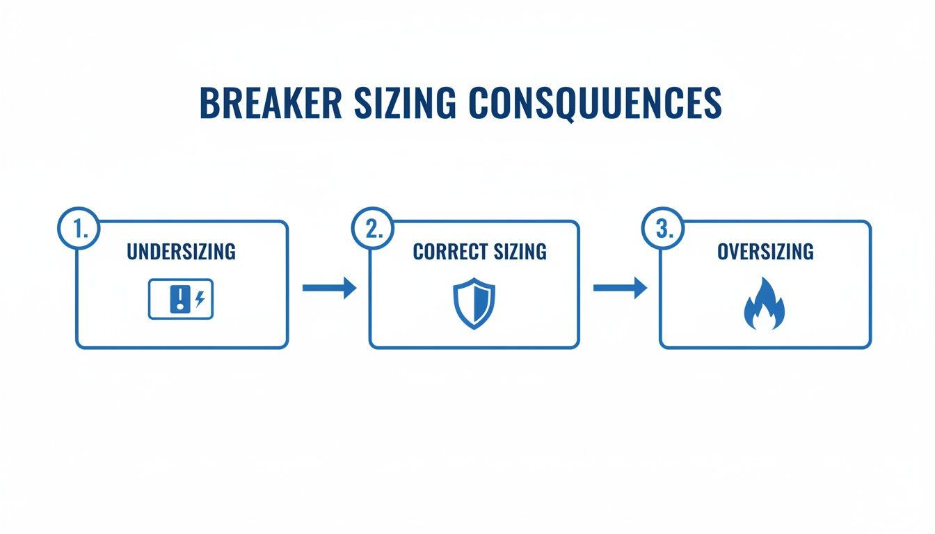
As you can see, undersizing causes constant tripping and downtime. Oversizing is even worse—it creates a serious fire risk by not protecting the wire. Correct sizing is the only option for a safe, reliable system.
A Practical Calculation Example
Let's walk through a typical industrial control panel scenario. You're sizing a breaker for a branch circuit with a mix of loads:
- A 1,500-watt process heater (definitely Continuous)
- A small control transformer with a 2A primary draw (Continuous)
- A standard convenience outlet for occasional tool use (Non-Continuous)
First, we need everything in amps. On a 120V single-phase circuit, the math looks like this:
- Heater FLA: 1500W / 120V = 12.5A (Continuous)
- Transformer FLA: 2A (Continuous)
- Outlet FLA: The NEC considers a standard outlet 1.5A for these calculations (Non-Continuous)
Now, we apply the NEC factors to see what the circuit actually needs to handle. The table below breaks down how the 125% rule for continuous loads and the 100% rule for non-continuous loads are applied.
Continuous vs Non-Continuous Load Calculation Examples
| Load Type | Nameplate FLA | NEC Factor | Calculated Load Amps |
|---|---|---|---|
| Process Heater (Continuous) | 12.5 A | 125% | 15.63 A |
| Control Transformer (Continuous) | 2.0 A | 125% | 2.50 A |
| Convenience Outlet (Non-Continuous) | 1.5 A | 100% | 1.50 A |
Adding these up, our total calculated load is 19.63 amps.
This means you must choose the next standard-size breaker above that value. A 20-amp circuit breaker is the correct and only safe choice here. A 15-amp breaker would trip constantly, and a 25-amp breaker would fail to protect the circuit wiring from overheating. This simple, methodical calculation is the foundation of a safe and compliant system.
Sizing a breaker for a simple, continuous load is one thing. But the real challenge begins when you start dealing with demanding, inductive loads.
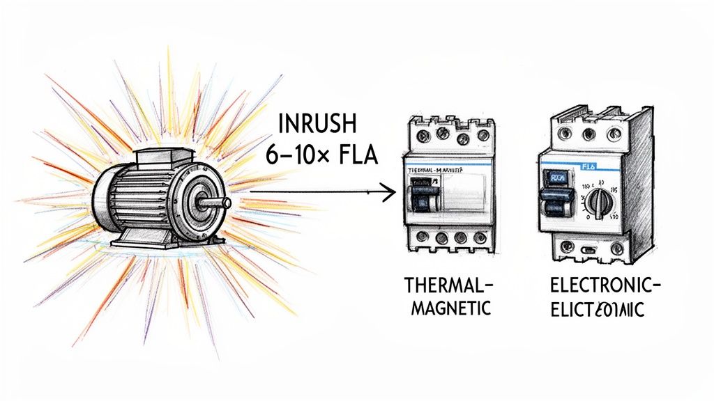
Industrial motors are the classic example here, and they're one of the biggest headaches because of the massive inrush current they pull the instant they fire up.
This initial surge can easily spike to 6 to 10 times the motor's normal Full Load Amps (FLA). Think about it: a 20-amp motor might momentarily draw 120 amps or more for a few critical seconds as it gets up to speed. A standard breaker sized for the 20-amp running load would see that as a catastrophic failure and trip immediately. The result? Nuisance tripping and frustrating production halts.
The trick is to find a breaker that can ride out this predictable startup surge without compromising its core job of protecting the circuit from a genuine fault. This is where understanding breaker trip characteristics becomes absolutely essential.
Choosing the Right Breaker Type for Motors
When you're dealing with motors, you quickly learn that not all circuit breakers are created equal. The two main players you'll be working with are thermal-magnetic and electronic trip breakers, and each has its place.
- Thermal-Magnetic Breakers: These are the rugged workhorses you see everywhere. The "thermal" part is a bimetallic strip that heats up and trips on sustained overloads, while the "magnetic" part is an electromagnet that trips instantly on a short circuit. For motors, you need one with a specific trip curve—often called a "D-curve"—that's intentionally designed to ignore high inrush currents for a few moments.
- Electronic Trip Breakers (Motor Circuit Protectors): These are the high-precision tools of the trade. They use current transformers and smart electronics to monitor the circuit, which gives you incredible control. You can dial in the exact trip settings for both long-time overloads and instantaneous faults, perfectly matching the breaker's response to a specific motor's startup profile.
A standard thermal-magnetic breaker can get the job done, but an electronic motor circuit protector gives you the fine-tuning you need for high-inertia loads or tricky applications. This level of control is also a huge part of learning how to properly size a motor starter, since the breaker and starter have to work together as a complete protection system.
Navigating NEC Article 430 for Motor Circuits
Thankfully, we have a rulebook for this. The National Electrical Code gives us specific guidance for motor circuits in Article 430. This section is your best friend, and it explicitly allows you to size a motor's short-circuit protection much higher than its running current.
NEC Table 430.52 lays out the maximum allowable percentage of the motor's FLA for an inverse-time circuit breaker. Depending on the motor, this can be as high as 250% of the FLA.
This feels wrong at first, doesn't it? Why put a 50-amp breaker on a motor that only draws 20 amps? Because the breaker isn't there for overload protection—that's the job of the overload relay in the motor starter. The breaker's primary role is to handle a dead short.
Let's walk through a quick example for a common 460V, 10 HP induction motor with an FLA of 14 amps:
- Find the FLA: Per NEC Table 430.250, a 10 HP motor has an FLA of 14A.
- Apply the Multiplier: Using NEC Table 430.52, the maximum rating for our inverse-time breaker is 250% of FLA.
- Calculate Max Breaker Size: 14A x 2.50 = 35A.
- Select the Breaker: You can use a standard breaker up to 35A. A 30A or 35A breaker is a common and compliant choice here, giving that motor plenty of breathing room during startup.
Other Demanding Industrial Loads
While motors are the star of the show, they aren't the only demanding loads you'll encounter. Transformers and Variable Frequency Drives (VFDs) also need special attention.
- Transformers: These have their own magnetic inrush current when first energized. NEC Article 450 provides the sizing rules, typically allowing protection up to 125% of the primary current, with some exceptions letting you go as high as 250%.
- VFDs: VFDs have a soft-start feature that smooths out motor inrush, but the drives themselves create their own inrush to charge up their internal capacitors. Always, always check the VFD manufacturer's manual. They will recommend a specific breaker type and size to protect the drive's sensitive electronics.
For the engineers and integrators out there, this means you have to match breaker trip ratings to those inrush currents—often 6-10 times the full load amps. Getting this wrong is a big reason for the 15-20% failure rate we see from undersized units in MV switchgear. It's a tough job, especially since many of these systems are in outdoor applications like oil & gas that demand weatherproof designs, while others need gas-insulated breakers for high-voltage reliability.
Matching Conductors with Breaker Ratings
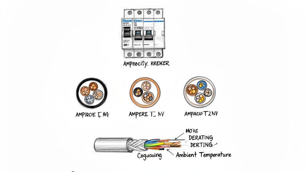
A perfectly sized circuit breaker is worse than useless if the wire it's supposed to protect can't handle the current. In fact, it's downright dangerous. The breaker's fundamental job is to keep the conductor from overheating, and if the wire is too small for the breaker, you've just installed a fire hazard.
This relationship between the breaker and the wire is the final, critical piece of the puzzle. You've already calculated the load and accounted for any inrush, but none of that matters if you don't select a wire with an ampacity—its safe current-carrying capacity—that meets or exceeds the breaker's rating.
Using the NEC for Wire Ampacity
Your go-to resource here is NEC Table 310.16. This is where the code lays out the allowable ampacity for various gauges of copper and aluminum wire, based heavily on their insulation temperature rating. For most industrial work, you'll be looking at the 75°C and 90°C columns.
It's a common rookie mistake to just grab the 90°C value because it lets you use a smaller, cheaper wire. But hold on. NEC 110.14(C)(1) throws a wrench in that plan, stating that the entire circuit's temperature rating is limited by its weakest link. Most circuit breakers and terminal blocks are only rated for 75°C, which effectively makes the 75°C column your real-world limit.
A wire might have 90°C insulation, but if it lands on a 75°C breaker terminal, you must use the 75°C ampacity value. The connection point is the weakest link in the thermal chain, and the code forces you to design for it.
The Overlooked Impact of Derating Factors
Picking a wire size from the table is just the beginning. The real world of industrial facilities is rarely as neat as a codebook table. The NEC requires us to "derate," or reduce, a conductor's listed ampacity to account for two huge variables: ambient temperature and conduit fill.
These aren't suggestions; they're mandatory calculations for a safe, compliant installation.
Adjusting for Ambient Temperature
Many industrial spaces aren't sitting at a comfortable room temperature. A control panel in a hot warehouse or baking in the sun will operate far above the standard 30°C (86°F) baseline used in the NEC tables.
As wires get hotter, their ability to carry current safely drops. You'll need to turn to NEC Table 310.15(B)(1) for the correction factors. For example, a wire running through a space with an ambient temperature of 40°C (104°F) only keeps 88% of its listed ampacity. That small difference can easily bump you up to the next wire gauge. Our guide on voltage drop calculation formulas offers more context on how temperature affects electrical systems.
Adjusting for Conduit Fill
Another critical factor is how many current-carrying conductors you're pulling into a single conduit. Every wire generates heat, and when they're bundled together, that heat has nowhere to go.
NEC Table 310.15(C)(1) forces a reduction in ampacity as soon as you have more than three current-carrying conductors in a raceway. The penalties get steep, fast.
- 4-6 Conductors: Ampacity drops to 80%.
- 7-9 Conductors: Ampacity is cut to 70%.
- 10-20 Conductors: Ampacity is slashed to just 50%.
As you can see, this has a massive impact. Running ten conductors in one pipe literally cuts their effective capacity in half, forcing you into a much larger and more expensive wire to do the same job.
A Real-World Derating Example
Let's walk through a common scenario. You’ve determined a 40A circuit breaker is right for a motor load. You plan to run THHN copper wire in a conduit that already holds five other current-carrying conductors. To make things interesting, the facility is hot, with an ambient temperature of 45°C (113°F).
- Pick a Starting Wire: Looking at NEC Table 310.16 (in the 75°C column), an 8 AWG copper wire is rated for 50A. On paper, that seems perfect.
- Apply Temperature Derating: At 45°C, the NEC correction factor is 0.82. So, our wire's true ampacity is now 50A x 0.82 = 41A. Still looking good.
- Apply Conduit Fill Derating: We have six total conductors, so the adjustment factor is 0.80. Now we calculate the final ampacity: 41A x 0.80 = 32.8A.
That 8 AWG wire is no longer sufficient. It can only safely carry 32.8A, yet it's being protected by a 40A breaker. That’s a code violation and a serious safety risk waiting to happen.
The only solution is to upsize the wire. A 6 AWG copper wire, with its base ampacity of 65A, would be the right call here, as its final derated value would still land safely above the 40A breaker rating.
Verifying Short Circuit and Interrupting Ratings
You’ve done the hard work. You’ve calculated your loads, wrestled with motor inrush, and meticulously derated your conductors. But there’s one final, absolutely critical safety check that separates a reliable system from a catastrophic failure waiting to happen.
We need to talk about what happens when things go really wrong—during a dead short.
This is where two of the most important terms in electrical safety come into play: Ampere Interrupting Capacity (AIC) and Short Circuit Current Rating (SCCR). These ratings aren't about normal operation; they are all about a component's ability to survive a worst-case scenario.
AIC vs. SCCR: What's the Difference?
It's easy to get these terms mixed up, but they represent two sides of the same safety coin. Getting the distinction right is fundamental.
- Ampere Interrupting Capacity (AIC): This rating applies specifically to overcurrent protective devices like circuit breakers and fuses. Think of it as the maximum fault current a breaker can safely interrupt without exploding or welding its contacts shut.
- Short Circuit Current Rating (SCCR): This is a broader rating that applies to an entire assembly, like a UL508A control panel, or to individual components like terminal blocks and contactors. It’s the maximum fault current the component or assembly can withstand without causing a fire or shock hazard.
The core principle is simple but completely non-negotiable: your circuit breaker’s AIC rating must be greater than or equal to the available fault current where it's installed.
Think of it this way: if a pipe in your house can only handle 100 PSI, you wouldn't connect it to a city water main pumping out 150 PSI. The same logic applies here. Installing a breaker with a 10,000A AIC rating in a location where 22,000A of fault current is available is a recipe for disaster.
Estimating Available Fault Current
Calculating the precise available fault current at every point in a large facility is a complex engineering task. Luckily, for most control panel and equipment applications, you can use a simplified, conservative approach to ensure safety.
The rule of thumb is that fault current is always highest closest to the power source (the utility transformer) and decreases as you move downstream.
Imagine a large manufacturing plant. The main switchgear right after the utility transformer might see an available fault current of 65,000 amps (65kA). This means the main breaker in that panel must have an AIC rating of at least 65kA.
Now, picture a small motor control panel located 200 feet away, fed by a long run of smaller wire. The impedance of that wire will naturally limit the fault current. At that downstream panel, the available fault current might only be 18,000 amps (18kA). In this spot, a standard breaker with a 22kA AIC rating would be perfectly safe and compliant.
For anyone specifying equipment, a key piece of information you need from the end-user or facility manager is the available fault current at the point of connection. Without it, you're just guessing.
Coordinating SCCR in UL508A Panels
This concept gets really important when you're designing custom control panels. According to UL508A standards, the entire panel assembly gets an overall SCCR, and that rating is limited by the lowest-rated component in the entire power circuit.
You could have a main breaker with a 65kA AIC rating, but if you install a power distribution block rated for only 10kA, the entire panel’s SCCR is now just 10kA. For a deeper look at specific components, exploring options from a reputable ABB circuit breaker distributor can show you what's possible with high-rated components.
This is why coordination is everything. Every single component in the path of a potential fault—from the main breaker to contactors, terminal blocks, and overload relays—must have an SCCR that meets or exceeds the required rating for the panel. Verifying these ratings is the final step that ensures your carefully sized system doesn't just work, but fails safely.
Common Questions on Sizing Circuit Breakers
Even when you have the fundamentals down cold, real-world projects have a way of throwing curveballs. Sizing circuit breakers means you're constantly juggling codes, equipment quirks, and the specific demands of the application. Let's dig into some of the most common questions and hang-ups that pop up in industrial settings.
Think of these as the bridge between theory and what actually happens on the plant floor. Getting these right is how you build a system that's not just compliant, but genuinely reliable.
What Is the Difference Between a Standard and a 100% Rated Breaker
This question comes up all the time, and the answer really boils down to heat. A standard thermal-magnetic circuit breaker isn't built to run at its nameplate rating forever. It's actually designed to handle only 80% of its rated current on a continuous basis—that's why we have the 125% sizing rule for continuous loads. If you try to run a standard breaker at its full rating for more than three hours, it's going to get hot and trip.
A 100% rated circuit breaker is a different beast. It's built with components that can handle and dissipate the heat from carrying its full rated current indefinitely, and it goes through much tougher testing to prove it.
So, when would you use one? They're often specified for tight spots, like a packed control panel where every bit of space counts and getting rid of heat is a challenge. But it's not a simple swap. To use a 100% rated breaker correctly, the conductors connected to it must also be sized for 100% of the load using their 90°C ampacity, and you have to use lugs that are specifically rated for that higher temperature.
Can I Just Use a Larger Breaker if Mine Keeps Tripping
Let's be blunt: absolutely not. A frequently tripping breaker is a warning sign, not an annoyance. Swapping it for a bigger one is like yanking the battery out of a smoke detector because the alarm is loud. You’re silencing the warning and creating a much, much bigger risk.
The breaker is sized to protect the wire. When you install a bigger breaker, you’re giving it permission to let more current flow through the wire than it can safely handle. That wire can quickly turn into a fire-starting heating element inside your wall.
Instead of reaching for a larger breaker, put on your detective hat. A tripping breaker is telling you something is wrong. The culprit is usually one of these:
- An Overloaded Circuit: You’re simply trying to run too much equipment on one circuit.
- A Failing Component: A motor with bad bearings, for instance, will draw more and more current until something gives.
- Incorrect Initial Sizing: It's possible the original design didn't properly account for inrush currents or the true continuous load.
Figuring out the why is everything. If you're dealing with nuisance tripping, it's critical to understand the common reasons for Why Your Circuit Breaker Keeps Tripping before you can safely solve the problem.
How Does a Variable Frequency Drive Change Breaker Sizing
Variable Frequency Drives (VFDs) throw a wrench in the standard motor protection playbook. In one sense, they make life easier. The VFD's soft-start capability gets rid of that massive inrush current from the motor, which means you don't have to oversize the breaker to 250% just to get the motor started.
But VFDs bring their own baggage to the party. The drive itself has an inrush current when it first powers on to charge its internal capacitors. More importantly, the drive is full of sensitive electronics that need their own special kind of protection.
Because of this, you should always follow the VFD manufacturer's specific guidelines for the upstream breaker. The VFD manual will tell you exactly what you need—usually a specific thermal-magnetic breaker or fuse class and a maximum size. This protection isn't really for the motor anymore; it's about protecting the expensive VFD from short circuits and other faults.
At E & I Sales, we bring decades of hands-on experience to every project, from supplying the right components to designing and building custom UL-listed control panels. If you need a partner who understands the nuances of industrial motor control and circuit protection, we're here to help you get it right the first time. Visit us at https://eandisales.com to learn more.