
Picture this: you've just been handed a frosty mug of beer.
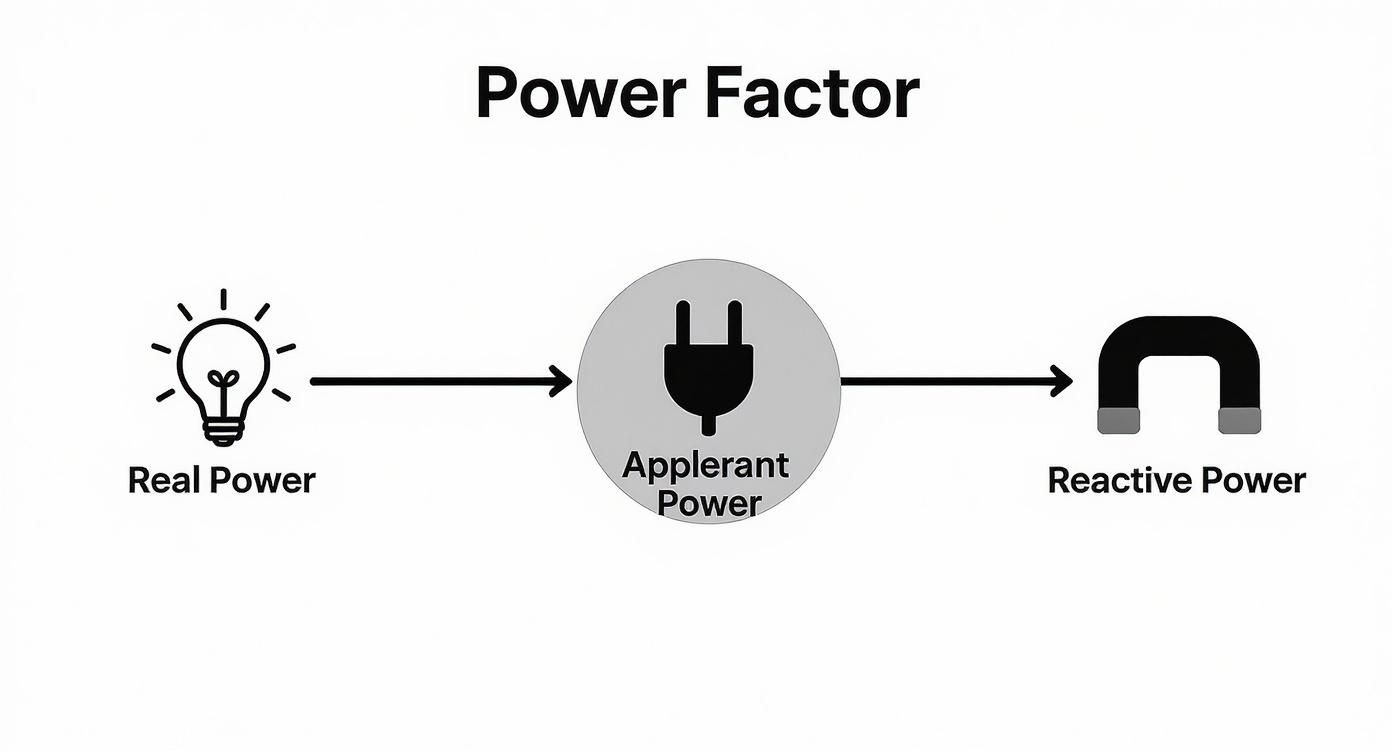
The whole thing—glass, beer, and foam—is the total power your facility is pulling from the grid. But it's only the actual beer that does you any good. That's your Real Power, the stuff that actually runs your motors and keeps the lights on.
That thick layer of foam at the top? It takes up space in the mug, but you can't drink it. That's your Reactive Power. It's not doing any real work, but the utility still has to supply it.
Power factor is simply the ratio of the good stuff (the beer) to the entire mug.
So, What Is Power Factor, Really?
At its heart, power factor is a straightforward measure of electrical efficiency. It’s a number between 0 and 1 that tells you how effectively your equipment is turning electricity into useful work.
A perfect score is 1.0 (unity). This means every last drop of power sent to your facility is being put to productive use. But if your power factor is, say, 0.75, you're only using 75% of the power you're drawing. The other 25% is essentially wasted energy that's just circulating in your system.
This isn't just some abstract number, either. That "wasted" power puts a real strain on your cables and transformers. More importantly, it shows up on your utility bill. Power companies have to generate and deliver that extra non-productive power, which stresses their grid, so they often hit facilities with low power factor with some hefty penalties.
The Three Amigos of Electrical Power
To really get a handle on power factor, you need to understand the three distinct types of power that make it up. Engineers often talk about the "power triangle," but let's stick with our beer analogy.
-
Real Power (kW): This is the beer. It’s the power that gets the job done—turning motor shafts, heating elements, and lighting up your plant. It’s measured in kilowatts (kW), and it's what you actually want and need.
-
Reactive Power (kVAR): This is the foam. It's the power required by equipment like motors and transformers just to create their magnetic fields. While it’s necessary for them to operate, it performs zero tangible work. It's measured in kilovolt-amperes reactive (kVAR).
-
Apparent Power (kVA): This is the whole mug. It’s the combination of Real Power and Reactive Power, representing the total power your utility has to supply to your doorstep. This is measured in kilovolt-amperes (kVA).
Here's a quick cheat sheet to keep these straight:
The Three Types of Electrical Power at a Glance
| Power Type | What It Does | Unit of Measurement | Analogy (Beer Mug) |
|---|---|---|---|
| Real Power | Performs actual, useful work. | Kilowatts (kW) | The beer |
| Reactive Power | Creates and sustains magnetic fields. | Kilovolt-Amperes Reactive (kVAR) | The foam |
| Apparent Power | The total power supplied by the utility. | Kilovolt-Amperes (kVA) | The entire mug |
Understanding these three components is the key to unlocking better efficiency.
Power factor is a fundamental concept in electrical engineering, defined as the ratio of real power (measured in watts, W) to apparent power (measured in volt-amperes, VA) in an alternating current (AC) power system. A power factor of 0.8 means that only 80% of the electrical power is doing useful work, while 20% is wasted. You can explore a more detailed technical breakdown of the power factor on Wikipedia.
Ultimately, getting a grip on what power factor means is the first, most crucial step toward a more efficient facility. When you improve your power factor, you’re not just trimming energy waste—you're cutting operating costs and freeing up electrical capacity to help your plant grow.
Identifying the Causes of Poor Power Factor
Okay, so you get the concept of power factor. But knowing the definition and finding the real-world culprits dragging it down in your facility are two different things. Poor power factor isn’t some random fluke; it’s a direct result of the equipment you fire up every single day.
The main offenders are devices that need reactive power to do their job, which in turn creates a phase shift between voltage and current.
This is almost always tied to something called inductive loads. Just think of anything that runs using magnetic fields. To build and maintain those fields, this equipment constantly sips reactive power (kVAR)—the "foam" in our beer analogy. This isn't "working" power, but it still puts a strain on your electrical system, making the current lag behind the voltage.
The more of these inductive loads you have running, the bigger that lag gets, and the further your power factor plummets. Finding these machines is the first step to fixing the electrical waste in your plant.
This diagram really helps visualize how the different types of power relate to each other and define your power factor.
As you can see, the Apparent Power you pull from the utility is a combination of the Real Power doing useful work and the Reactive Power that isn't. When that reactive slice of the pie gets too big, your efficiency tanks.
Common Inductive Loads in Industrial Settings
So, what specific gear should you have your eye on? In most plants and commercial buildings, a few usual suspects are responsible for almost all the reactive power demand.
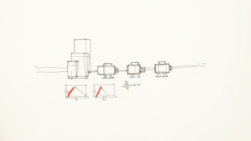
- AC Induction Motors: These are, without a doubt, the single biggest contributors. They are the absolute workhorses of industry, running everything from pumps and fans to conveyors and compressors. Their entire operation depends on creating a rotating magnetic field, which is a massive consumer of reactive power, especially when they aren't fully loaded.
- Transformers: Every facility has transformers stepping voltage up or down. Just like motors, they rely on magnetic induction and need a steady diet of reactive power to function.
- Welding Equipment: Arc welders and similar induction-based machines also generate powerful magnetic fields to operate, adding to the inductive load on your system.
- High-Intensity Discharge (HID) Lighting: If you’re still using older lighting like mercury vapor or high-pressure sodium lamps, their magnetic ballasts are highly inductive and contribute to the problem.
The combined impact of these loads can be huge. A single motor might not seem like a big deal, but hundreds of them running across a facility can easily drag the plant's power factor down to 0.80 or lower, and that’s when you start seeing those painful utility penalties on your bill.
Why Lightly Loaded Motors Are a Problem
Here’s a common misconception: a motor running at partial capacity must be more efficient, right? Wrong. When it comes to power factor, it’s actually the opposite.
An induction motor draws a fairly constant amount of reactive power just to keep its magnetic field energized, no matter how much mechanical work it’s actually doing.
This means a motor chugging along at 50% of its rated load will have a much worse power factor than one running at 90% load. While the real power (kW) it uses goes down, the reactive power (kVAR) it needs stays pretty much the same. Suddenly, the "foam" (kVAR) takes up a much larger percentage of the total "mug" (kVA).
This is exactly why sizing motors correctly for the job is so critical—not just for mechanical performance, but for your electrical health. If you think you might have oversized or underloaded motors, it’s worth investigating your options. You can learn more about the wide range of electric motors available to make sure you've got the right tool for the job. Pinpointing and fixing these specific sources of inefficiency is the only way to get your power factor back where it needs to be.
The Real-World Costs of a Low Power Factor
Understanding the theory behind power factor is one thing. Watching it hit your bottom line makes it a problem you can't afford to ignore.
A low power factor isn't just a technical footnote for engineers; it's a financial anchor dragging on your profitability. The consequences pop up everywhere, from glaring penalties on your utility bill to hidden stress on your entire electrical system.
When you have poor efficiency, you're literally paying for electricity you can't even use. The utility still has to generate and transmit that non-productive reactive power, and you can be sure they’re passing that cost right along to you.
Direct Financial Penalties from Your Utility
The most immediate—and painful—cost of a low power factor comes straight from your electricity provider. Most utilities tack on a power factor surcharge or penalty for their commercial and industrial customers.
This isn't just some minor fee. It’s a serious financial motivator designed to push businesses to operate more efficiently and reduce the strain on the grid.
These penalties kick in when your facility's power factor drops below a certain threshold, typically 0.95 or 0.90. If your plant is humming along at a 0.85 power factor, you're not just paying for the real power (kW) you actually used. You're also getting an extra bill for the excessive reactive power (kVAR) you demanded.
These surcharges can bloat a facility's electricity costs by several percentage points. For a medium-sized operation, that can easily add up to thousands—or even tens of thousands—of dollars a year. It's a direct, measurable expense that bleeds your budget month after month.
Increased Energy Losses and Wasted Money
Beyond the utility bills, a low power factor creates expensive problems inside your own facility. All that extra reactive current sloshing around your system doesn't do any work, but it definitely generates heat. This is all thanks to I²R losses, where "I" is the current and "R" is the resistance of your wiring.
Because a low power factor demands higher total current to deliver the same amount of useful power, your I²R losses climb exponentially. This waste shows up in a few ways:
- Wasted Energy: Your cables, transformers, and switchgear get warmer than they should, burning off energy as heat instead of powering your machines. It's electricity you paid for, vanishing into thin air.
- Higher Cooling Costs: In places like data centers or climate-controlled production areas, that extra heat forces your HVAC system to work overtime, inflating your energy bills even further.
These internal losses might not be a separate line item on a bill, but they represent a constant and significant financial leak.
Crippled System Capacity and Avoidable Upgrades
This might be the most damaging consequence in the long run. A low power factor puts a chokehold on your entire electrical distribution system. Your transformers, switchgear, and cables are all rated for a maximum apparent power (kVA). When useless reactive current hogs that capacity, there’s less room for the real power that actually makes you money.
Picture this: A facility's main transformer is running at 95% of its kVA capacity. But because the power factor is a dismal 0.75, only about 71% of that capacity is doing productive work. The rest is just electrical dead weight.
Now, let's say you need to add a new production line.
Even though you have enough real power headroom, your transformer is screaming for help. Your only options are a costly, disruptive upgrade of your electrical service or fixing the power factor. By simply improving the power factor to 0.95 or higher, you could free up over 20% of your system's capacity without buying a single new transformer. That new equipment could be installed tomorrow, avoiding a massive capital expense.
This is exactly why a poor power factor is often called a "capacity thief." It steals the potential of the infrastructure you already own. In fact, data shows that poor power factor can drive system losses 20-30% higher than in a well-run facility. To dig deeper into these figures, you can learn more about the economic impact of the power factor from leading industry sources.
How to Measure and Analyze Your Power Factor
Alright, let's move from theory to action. To fix a low power factor, you first have to figure out what's actually happening on your shop floor. It's all about gathering the right data, identifying the main culprits, and seeing exactly where the utility is hitting you on your bill.
The good news? You don't need to be a seasoned electrical engineer to get started. The first clues are usually hiding in plain sight.
Start with Your Utility Bill
Your monthly electricity bill is the absolute best place to start your investigation. Utilities love to bill for poor efficiency, but they don't always call it the same thing.
Comb through the line items and look for these tell-tale signs:
- Power Factor Surcharge/Penalty: This one is pretty straightforward. It's a direct penalty for dropping below their target, which is often 0.95.
- kVAR Demand Charge: Some utilities bill you directly for peak reactive power demand. Think of this as a charge for all that "foam in the beer" your equipment is demanding from the grid.
- kVA Billing: This is a sneaky one. If your bill is based on apparent power (kVA) instead of just real power (kW), a low power factor is guaranteed to inflate your demand charges.
If you spot any of these, you have your smoking gun. Poor power factor is already costing you money, month after month. This is the ammo you need to build a business case for fixing it.
Using the Right Diagnostic Tools
While your utility bill confirms you have a problem, you need professional tools to pinpoint the cause. The go-to instrument for this job is a power quality analyzer.
This is a specialized piece of gear you can clamp onto your electrical feeders to record incredibly detailed data over time. It measures everything: voltage, current, real power (kW), reactive power (kVAR), apparent power (kVA), and, of course, power factor.
By logging this data, you can see how your power factor fluctuates as different machines kick on and off throughout the day. This is how you connect a low power factor reading to a specific piece of equipment or operational schedule.
Conducting a Basic Power Factor Study
With an analyzer in hand, you can conduct a quick study to get a clear picture of your system's health. It’s a pretty logical process.
Here’s how a successful study usually plays out:
- Measure at the Main Service: First, hook up the analyzer right where power enters your building. This gives you the big-picture view—the exact power factor your utility is seeing and billing you for.
- Identify Large Inductive Loads: Walk the floor and make a list of your biggest potential offenders. We're talking large motors, compressors, grinders, and welders. These are your prime suspects.
- Measure at Key Distribution Panels: Now, move the analyzer downstream to the panels feeding those high-horsepower motor loads. This is how you isolate which areas of the plant are the biggest contributors to the problem.
- Analyze the Data: It's time to connect the dots. Compare the power factor readings from different spots. If you see a major drop at a panel feeding a motor control center, you've found exactly where your reactive power demand is coming from.
This systematic approach takes a vague, facility-wide problem and turns it into a targeted hit list of inefficient equipment. The data you gather here is the foundation for designing a correction strategy that actually works.
So, you’ve found a low power factor in your facility. What’s next?
Fixing it, of course. The good news is that this is a well-understood problem with tried-and-true solutions. Think of it like rebalancing a wobbly tire—the goal is to counteract the forces throwing your system out of whack and restore smooth, efficient operation.
The core issue, as we've seen, is the excessive reactive power (kVAR) that inductive loads like motors demand from the grid. The fix is surprisingly simple in concept: supply that reactive power right at the source. Doing this takes the strain off the utility, cuts the total current flowing through your wiring, and nudges your power factor back toward the perfect 1.0.
Capacitor Banks: The Go-To Solution
For most industrial and commercial applications, the most common and cost-effective tool in the toolbox is the capacitor bank.
If inductive loads are the problem, capacitors are the antidote. They generate leading reactive power, which directly cancels out the lagging reactive power that motors and transformers gobble up.
Imagine your big induction motor is constantly "borrowing" reactive power from the utility to keep its magnetic fields spinning. A capacitor bank acts like a small, on-site energy reservoir that "lends" that power to the motor instead.
Because this transaction now happens locally, that reactive power no longer has to travel all the way from the power plant. This one change dramatically lowers the total current in your system, which cuts down on heat losses and frees up electrical capacity you didn't even know you had.
Fixed vs. Automatic Capacitor Banks
Not all capacitor banks are built the same. Picking the right type—fixed or automatic—is a critical decision that depends entirely on how your facility operates.
-
Fixed Capacitor Banks: These are the simple, no-frills option. They deliver a constant, unchanging amount of correction. You’ll often see them wired directly to a large, continuously running motor. They are a great "set it and forget it" solution for a single, steady load but are a poor choice for facilities with fluctuating power needs.
-
Automatic Capacitor Banks (APFC): This is the smarter, more dynamic approach. An APFC panel is a cabinet full of individual capacitor "stages" managed by an intelligent controller. The controller constantly watches your facility's power factor and switches these stages on and off as needed, delivering the perfect amount of correction in real time.
Key Takeaway: For any facility with varying loads—like a factory where machines start and stop all day—an automatic capacitor bank is almost always the right call. It keeps you from over-correcting, which can be just as bad as not correcting at all.
Other Advanced Correction Methods
While capacitors handle the bulk of PFC work, a few other technologies come into play for more specialized or heavy-duty situations.
Synchronous Condensers
In massive operations like steel mills or mines, you might find a synchronous condenser. This is essentially a huge synchronous motor running without any mechanical load attached. By tweaking its field excitation, operators can make it generate or absorb massive amounts of reactive power, giving them incredibly precise, dynamic control over the grid.
Active Filters
Today's facilities are packed with VFDs, LED lights, and other electronics that create another power quality headache: harmonic distortion. An active harmonic filter is a sophisticated piece of power electronics that not only corrects for power factor but also injects opposing currents to cancel out those damaging harmonics.
This connection between power factor and harmonics is crucial. For a solid foundation, check out our guide on variable frequency drive basics.
To help you navigate these options, here’s a quick comparison of the most common PFC methods.
Comparing Power Factor Correction Methods
Choosing the right technology is key to a successful PFC strategy. This table breaks down the main options to help you decide which approach best fits your facility's needs and budget.
| Correction Method | Best For | Pros | Cons |
|---|---|---|---|
| Fixed Capacitor Banks | Individual, constant loads (e.g., a large motor that runs 24/7). | Simple, low cost, easy to install. | Can cause overcorrection if the load turns off; no flexibility. |
| Automatic Capacitor Banks | Facilities with multiple, varying loads (most manufacturing plants). | Highly efficient, prevents overcorrection, adapts to changing needs. | Higher initial cost, more complex installation. |
| Synchronous Condensers | Utility-scale or very large industrial applications (mining, steel mills). | Extremely precise and dynamic control; can absorb or generate reactive power. | Very expensive, large physical footprint, requires significant maintenance. |
| Active Harmonic Filters | Facilities with high levels of non-linear loads (VFDs, electronics). | Corrects PF and eliminates harmonic distortion simultaneously. | Highest cost, primarily a power quality solution with PFC benefits. |
Ultimately, the goal is to pick the solution that provides the most effective correction without introducing new problems. For most, an APFC panel hits that sweet spot.
As you can see, the right method depends entirely on your load profile. The growing demand for electric vehicles, for example, makes boosting EV charging efficiency a key area where precise power factor control is essential for managing costs and grid stability.
Common Mistakes and Advanced Considerations
Getting power factor correction right is about more than just bolting a capacitor bank to the wall. It’s a balancing act, and a few common missteps can easily turn your solution into a whole new set of problems.
Two of the biggest tripwires in modern facilities are the risk of overcorrection and the chaotic influence of harmonic distortion.
The Dangers of Overcorrection
Simply throwing capacitors at an inductive load without a deeper look is a classic, and frankly dangerous, mistake. The idea is to neutralize reactive power, not swing the pendulum too far in the other direction.
Overcorrection happens when you have more capacitance online than your current inductive load requires. We see this all the time with fixed capacitor banks wired to motors that cycle on and off. When the motor shuts down, its inductive load disappears, but those capacitors just keep pumping reactive power into a system that has nowhere to put it.
This shoves your system into a leading power factor, which can be just as damaging as a lagging one. The fallout is often immediate and expensive:
- System Over-voltage: All that excess capacitive energy has to go somewhere, and it often shows up as a sharp, damaging spike in system voltage. This is poison for sensitive electronics, hard on motor insulation, and a primary cause of nuisance trips on breakers.
- Utility Penalties: The utility company doesn't care which direction your power factor is off. Just as they'll bill you for lagging PF, many will hit you with surcharges for a leading PF, too. Your "fix" just became another line item on the bill.
The real takeaway here is that power factor correction has to be dynamic. For any facility with loads that fluctuate, an Automatic Power Factor Correction (APFC) system isn't a luxury—it's essential. It intelligently switches capacitor stages in and out to chase a target PF, keeping you in the sweet spot without ever pushing the voltage too high.
Navigating the Challenge of Harmonics
The other elephant in the room is harmonic distortion. Think of it as electrical noise pollution, and it's absolutely everywhere in a modern plant thanks to the rise of non-linear loads. The biggest offenders? Variable Frequency Drives (VFDs), LED lighting, welders, and even the power supplies in your office computers.
Unlike a clean motor load that draws a smooth AC sine wave, these devices sip current in short, high-frequency gulps. This action injects distorted currents—harmonics—back into your electrical system.
This becomes a five-alarm fire when you introduce standard PFC capacitors. Your system's natural inductance combined with the new capacitors can accidentally create a resonant circuit, tuned perfectly to one of those harmonic frequencies.
When that happens, the circuit acts like an amplifier, taking a small harmonic current and magnifying it to destructive levels. This is where we see capacitor fuses blowing for no apparent reason, transformers overheating dangerously, and sensitive electronics failing mysteriously. Standard capacitor banks simply weren't built for a high-harmonic world. To get a better handle on this, check out our guide on using a harmonic filter for VFD systems.
If your plant relies heavily on VFDs or other non-linear loads, specialized PFC gear is non-negotiable. Detuned capacitor banks include reactors that shift the system's resonant point to a harmless frequency. For an even more robust fix, active harmonic filters act like noise-canceling headphones for your power, electronically eliminating harmonics while also correcting power factor.
At E & I Sales, we specialize in designing and implementing robust electrical solutions that account for these advanced challenges. From engineered UL-listed control panels to turnkey system integration, we provide the expertise to ensure your power factor correction project is safe, effective, and reliable for the long haul. Find out how we can help optimize your facility at https://eandisales.com.