
At its core, a Power Distribution Center (PDC) is the nerve center of your plant's electrical system. It’s the single point where massive, high-voltage power from the utility grid gets tamed, organized, and sent out to every piece of equipment on your floor.
Think of it as the quarterback of your entire operation, taking the raw power and distributing it precisely where it needs to go, ensuring everything from giant motors to sensitive control panels gets a clean, reliable feed.
Decoding the Role of a Power Distribution Center
Let’s use an analogy. Imagine the power coming from the utility is like a raging river—incredibly powerful, but far too chaotic and dangerous to be useful. A PDC acts like a sophisticated dam and irrigation system. It takes that raw, high-voltage flow, safely steps it down, and channels it into a network of smaller, manageable circuits.
Each of those smaller streams is perfectly sized for the equipment it feeds. Without that control, you’d have an unmanageable and hazardous surge of energy. The PDC provides the essential structure, protection, and a single point of command for your facility’s entire electrical backbone.
The Core Mission of a PDC
When you strip everything else away, a PDC is all about safety and operational reliability. It’s a purpose-built fortress designed to protect your people, your multi-million-dollar assets, and your production schedule from catastrophic electrical failures.
It accomplishes this mission through a few critical jobs:
- Voltage Transformation: It uses transformers to step down high utility voltage (like 13,800 volts) to a safe, usable plant voltage (typically 480 volts).
- Circuit Protection: It’s packed with circuit breakers and fuses that act as sentinels. They instantly cut power during an overload or short circuit, preventing equipment damage and fires.
- Centralized Control: By bringing all the main breakers and distribution points into one spot, it makes operations, maintenance, and emergency shutdowns straightforward and safe.
A well-engineered PDC is much more than a steel box full of wires. It's the foundation of your plant's uptime. It ensures a problem in one area doesn't trigger a domino effect, taking down the entire facility and costing you a fortune in lost production.
Beyond traditional fixed installations, it's also worth looking at how innovations in mobile energy solutions are changing the game for temporary or remote power needs.
The table below breaks down the essential functions of a PDC and why they matter in a real-world industrial setting.
| Function | Core Purpose | Operational Benefit |
|---|---|---|
| Voltage Reduction | To step down high-voltage utility power to safe, usable levels for plant equipment. | Prevents equipment damage from over-voltage and ensures compatibility with standard machinery. |
| Power Distribution | To divide the main power feed into multiple smaller, dedicated circuits. | Allows for isolated control and protection of individual machines or operational areas. |
| Overcurrent Protection | To automatically interrupt power flow during short circuits or overload conditions. | Protects expensive assets from electrical damage and significantly reduces fire hazards. |
| Centralized Control | To consolidate main disconnects and controls into a single, accessible location. | Simplifies maintenance, speeds up troubleshooting, and makes emergency shutdowns fast and effective. |
| Fault Isolation | To contain electrical faults to a single circuit, preventing a plant-wide outage. | Maximizes operational uptime by ensuring a localized problem doesn't cascade across the facility. |
| Metering & Monitoring | To measure and record electrical usage, voltage, and current for the facility. | Provides critical data for energy management, load balancing, and predictive maintenance. |
Each of these functions contributes to a more resilient, safe, and efficient operation.
Why Centralization Matters
The genius of the PDC lies in its centralized design. Instead of having a messy web of electrical panels scattered all over your plant, you get a single, organized source of truth for power management.
This makes life infinitely easier for your maintenance crews when they're troubleshooting an issue. It also makes critical safety protocols, like lock-out/tag-out procedures, simple and effective to implement. By consolidating all this hardware into one place—often a dedicated electrical house (e-house)—you build a tough, manageable, and secure power backbone for your entire plant.
Anatomy of a Power Distribution Center
To really get what a power distribution center does, you have to look past the heavy steel box and see the critical components working together inside. The best way to think of a PDC is as a highly specialized team, where every member plays a specific part in safely wrangling and delivering electricity. From the moment high-voltage power hits the enclosure, it starts a carefully controlled journey through a series of essential devices.
This entire flow is engineered to take raw, high-voltage utility power and tame it into a safe, reliable, and usable form for everything in your facility. The visual below really breaks down this core job, showing how the PDC acts as the vital link between the grid and your plant floor.
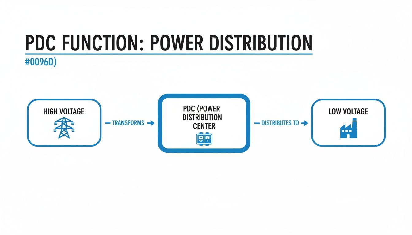
As the diagram shows, the PDC’s primary mission is simple but critical: take high-voltage power, step it down, and send it out as manageable low-voltage circuits ready for the real work.
The Main Incoming Section
The journey starts at the main incoming section. This is the single, secure gateway for all power entering the PDC. It’s where you’ll find the main circuit breaker or a fused switch, which acts as the master on/off switch for the whole system. This one point of control is absolutely essential for maintenance and emergencies, giving qualified people the ability to kill power to the entire center with one action.
This section is built like a fortress, engineered to handle the full force of the utility's available fault current. Its rugged design ensures it can withstand the incredible electrical forces of a short circuit, shielding all the downstream components from a catastrophic meltdown. Think of it as the main gatekeeper—controlling access and providing the first line of defense.
Transformers and The Main Bus
Once power is safely inside, its first stop is the transformer. You could argue this is the single most important component in the whole setup. Its job is to step down the high utility voltage—often 13.8 kV or even higher—to a usable plant voltage, like 480V. This transformation is what makes the electricity compatible with, and safe for, all your standard industrial motors and machines.
From the transformer, the now lower-voltage power flows to the main bus. This is the PDC’s superhighway. The main bus is a set of thick copper or aluminum bars that distribute power horizontally across the unit, feeding it to all the individual circuit breakers connected to your equipment.
The main bus is the central artery of your power distribution center. Its size and bracing are meticulously engineered to handle the total electrical load of your facility and withstand the powerful magnetic forces generated during a fault condition.
Circuit Breakers: The Guardians of Your Equipment
Branching off that main bus, you'll find the individual circuit breakers. These are the vigilant guardians protecting your expensive assets. Each breaker is sized for a specific circuit, constantly monitoring the current flowing to a motor, a production line, or a control panel. If it senses an overload or a short circuit, it trips automatically, instantly cutting off the power.
You’ll typically see a few common types of breakers inside a PDC:
- Molded Case Circuit Breakers (MCCBs): These are the workhorses for most branch circuits. They provide reliable, compact protection for loads usually under 1,200 amps.
- Insulated Case Circuit Breakers (ICCBs): A step up from MCCBs, these offer higher interrupting ratings and more advanced trip units, making them a great middle ground for more critical loads.
- Air Circuit Breakers (ACBs): Found on main disconnects and large feeder circuits, these are heavy-duty, often withdrawable devices built for high currents and the toughest industrial settings.
Getting the selection and coordination of these breakers right is non-negotiable. A properly designed system ensures that a fault on one small motor trips only its dedicated breaker, instead of causing a domino effect that shuts down an entire section of the plant. This strategic isolation is the secret to maintaining uptime and the hallmark of a well-engineered power distribution center.
Navigating Safety with UL Listings and Electrical Codes
In the high-stakes world of industrial power, safety isn’t a guideline—it's everything. When you're managing the kind of energy that flows through a power distribution center, there’s simply no room for error. This is exactly why third-party certifications and standardized electrical codes aren't just red tape; they are your most trusted partners in keeping people and equipment safe.
Think of these standards as a library of lessons learned the hard way, built from decades of real-world experience. Following them isn’t about checking a box. It’s about laying the foundation for a reliable, compliant, and fundamentally safe electrical system.
The UL Mark: More Than Just a Sticker
When you see that little UL mark on a power distribution center, it’s a big deal. It’s a public declaration that the entire piece of equipment has been pushed to its limits in a series of grueling safety tests by Underwriters Laboratories (UL), a name respected around the globe.
A UL-listed assembly, like a switchboard built to the UL 891 standard, has been tested as a complete, integrated system. This is a critical point. It confirms that all the individual parts—the breakers, the bus bars, the wiring—don't just meet their own standards but can work together safely under the immense stress of a full load or a fault condition.
That holistic certification gives you genuine peace of mind, knowing the PDC has been engineered to prevent foreseeable risks of fire, electric shock, and other hazards. It’s a crucial difference, and knowing the details matters. You can dig deeper into why a fully listed assembly is so vital for your project by understanding the difference between a UL Listed vs UL Recognized panels.
Playing by the Rules: The National Electrical Code
While UL confirms the equipment itself is built safely, the National Electrical Code (NEC), or NFPA 70, dictates how to install it safely. The NEC is the gold standard for electrical design and installation in the U.S., and you can bet your local inspector knows it inside and out.
For PDCs, a few parts of the code are especially important:
- Working Clearances (NEC 110.26): This isn't about giving technicians extra elbow room for comfort. It’s a strict requirement for unobstructed space around gear, ensuring they can do their job without being put in a dangerous, cramped position near live components.
- Grounding and Bonding (NEC Article 250): You could argue this is the single most important safety feature in any electrical system. Proper grounding gives fault currents a safe, easy path to follow, which allows breakers to trip in a fraction of a second and keeps lethal voltage off the metal enclosures of your equipment.
- Overcurrent Protection (NEC Article 240): This article lays out the rules for sizing and coordinating breakers. The goal is what’s called "selective coordination"—making sure that if a fault happens, the breaker closest to the problem is the only one that trips, isolating the issue without shutting down a whole section of your plant.
Nothing stops a project dead in its tracks faster than a failed electrical inspection. Partnering with a UL-certified panel shop that designs and builds to NEC standards from day one is the surest way to avoid expensive rework, infuriating delays, and the very real safety risks that come with non-compliance.
At the end of the day, UL listings and the NEC are two sides of the same safety coin. One proves the equipment is inherently safe. The other ensures it’s installed for a lifetime of safe operation. Together, they create the framework for a system that protects your people, your investment, and your peace of mind.
How to Size and Specify Your Power Distribution Center
Picking the right power distribution center isn't like grabbing a part off a shelf. It's a foundational engineering decision that dictates the safety, efficiency, and future of your entire operation. Getting it wrong leads to real consequences: dangerous under-protection, wasteful over-engineering, or a system that chokes the moment you try to expand.
You have to be methodical. The whole process kicks off with one simple but absolutely critical question: how much power do you actually need?
Calculating Your Total Electrical Load
First things first, you need to make a list. A really detailed list. I'm talking about every single piece of equipment that will pull power from this PDC. It's not just about the huge motors and conveyor systems; it’s the lighting panels, the HVAC units, the control cabinets—everything.
For each item, you need its full-load amperage (FLA) and voltage. And don't you dare forget about inrush current. Large motors can draw 5 to 8 times their normal running current for a split second on startup. If you only size for the running load, your main breaker will trip the moment a big motor kicks on.
Once you have your complete load list, you can add it all up. But let's be realistic—it's rare that every machine will be running at 100% capacity all at the same time. This is where demand factors, straight from the National Electrical Code (NEC), become your best friend. They help you size the system for how it will actually be used, saving a ton of money.
And whatever you do, plan for the future.
One of the most common and costly mistakes I see is sizing a power distribution center only for today's needs. A good rule of thumb is to add 20-25% additional capacity to your calculated load. This gives you room to grow without needing a massive, expensive overhaul in a few years.
Determining Voltage and Fault Current Ratings
With your load figured out, it's time to define the electrical environment your PDC will live in. You need to lock down the system voltage, which is usually set by what the utility provides and what your biggest machines need. Here in North America, 480V three-phase is the workhorse of industrial power.
Just as important is the available fault current. This is the absolute maximum amperage the grid can slam into your PDC during a dead short. It’s a scary number, and it’s one of the most critical safety metrics in your entire facility. You'll need an electrical engineer to perform a short-circuit study to get this value.
That number directly tells you what the Short Circuit Current Rating (SCCR) of your PDC needs to be. The SCCR is a measure of how well the gear can take a punch—its ability to withstand a massive fault without exploding or catching fire. The PDC's SCCR must be higher than the available fault current. There is zero room for negotiation on this. We dive deeper into all the factors that play into this in our guide on proper circuit breaker sizing.
Accounting for Environmental and Physical Constraints
Finally, you have to think about the real world. Where is this thing actually going to sit? The physical environment has a massive impact on the enclosure you choose and the components inside.
Ask yourself these questions:
- Location: Is it going inside a clean, climate-controlled e-house? Or will it be sitting outdoors, getting blasted by rain, snow, and scorching sun? This will determine the NEMA rating you need (like a NEMA 3R for outdoor gear).
- Atmosphere: Are you dealing with explosive gases or combustible dust? If it's a hazardous location, you're looking at specialized, explosion-proof enclosures and components.
- Footprint: How much real estate do you have? If you're crammed into a tight spot, you might need a custom-engineered layout or a multi-section design to make it fit.
Working through these questions will tell you if a standard, off-the-shelf design will work or if you need to go custom. Standard PDCs are great and cost-effective for many jobs, but a custom unit gives you the flexibility to handle unique voltages, specific brands, or a really challenging footprint. This way, you end up with a PDC that's not just good enough, but perfectly matched to your operation.
Integrating Power Centers With Automation Systems
A modern power distribution center is so much more than a passive electrical box. It’s an active, intelligent nerve center for your entire facility's operational network. A truly effective PDC doesn’t just shuttle power around; it talks, giving you a real-time window into the health and performance of your whole electrical system.
This leap—from silent hardware to a communicative asset—is one of the biggest advancements we've seen in industrial power management. When you integrate your PDC with your plant-wide automation systems, you’re tearing down the old walls between power and control. What you get is a single, unified ecosystem.
From Isolated Power To Connected Intelligence
In the old days, the power system and the control system were two separate worlds. The PDC did its job, the automation system managed the processes, but they rarely spoke the same language. Frankly, that model is obsolete.
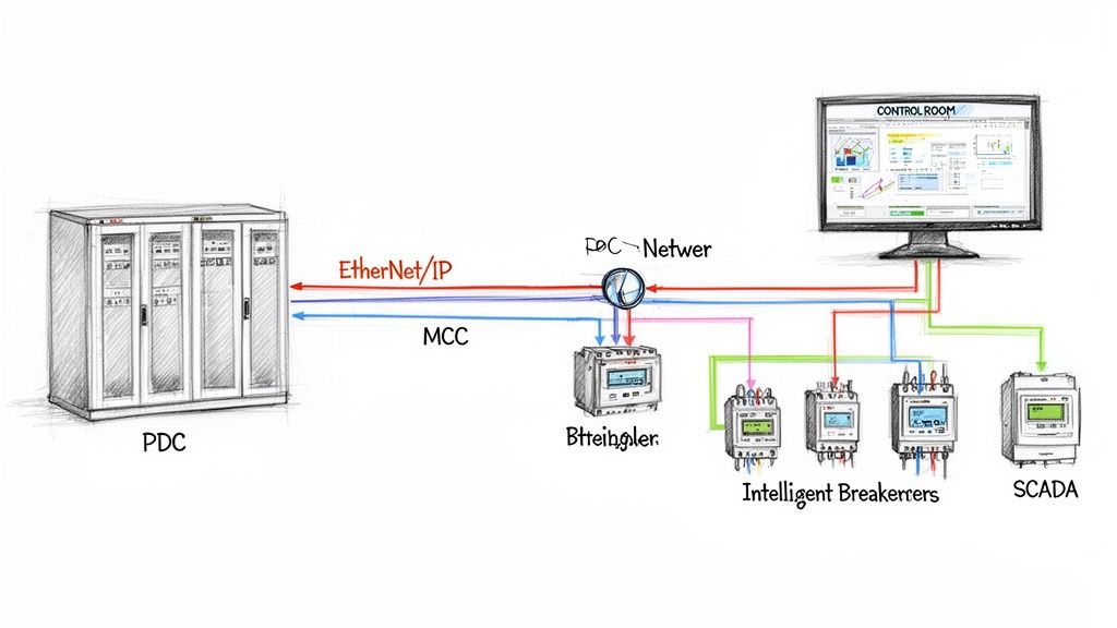
Intelligent devices are the bridge. Today’s circuit breakers, meters, and protective relays come equipped with communication capabilities right out of the box. Using standard industrial protocols like EtherNet/IP or Modbus TCP/IP, these devices feed a constant stream of valuable data from the PDC straight to your central control platform, whether that’s a Programmable Logic Controller (PLC) or a SCADA system.
This connectivity transforms the PDC from a simple electrical panel into a rich source of operational intelligence. It unlocks powerful new capabilities that were just a pipe dream with older, isolated setups.
What Integration Really Gets You
Hooking up your power and control systems isn't just a technical exercise; it delivers real, tangible benefits that hit your bottom line. The data flowing from your PDC provides deep insights that directly drive efficiency and reliability.
Here's what that looks like in practice:
- Real-Time Energy Monitoring: You can finally track power consumption down to the individual circuit. This lets you pinpoint energy-hogging equipment, get a handle on peak demand charges, and actually prove the ROI of any efficiency upgrades you make.
- Predictive Maintenance Alerts: Intelligent breakers can tell you when they’re nearing the end of their life or if they're seeing abnormal conditions. You can schedule maintenance on your own terms instead of reacting to a costly, middle-of-the-night failure.
- Instant Fault Diagnostics: When a breaker trips, the system doesn't just go dark. The smart device immediately pings the control room with a detailed alert, telling you the exact location and nature of the fault. This slashes troubleshooting time from hours to mere minutes.
By unifying your power distribution center with your automation network, you gain a holistic view of your facility's health. You can now see not just that a machine stopped, but why it stopped, all from a single control interface.
The move toward smarter, more data-driven power systems is accelerating across every industry. It’s especially true in the data center world, where uptime and efficiency are everything. The global Power Distribution Unit (PDU) market, currently valued at US$4.3 billion, is expected to hit US$6.1 billion by 2030, a surge driven almost entirely by the explosive growth of AI and cloud computing. You can dive deeper into the market forces shaping the future of power distribution technology.
Let's break down the real-world difference between a siloed approach and a modern, integrated one.
Comparing Integration Approaches
| Feature | Traditional Approach | Modern Integrated Approach |
|---|---|---|
| Data Visibility | Limited to local readouts. Information is trapped in the PDC. | Centralized, real-time data available in SCADA/HMI. |
| Troubleshooting | Manual process. Requires electricians with meters on-site. | Instant alerts with precise fault location and diagnostics. |
| Energy Management | Basic, plant-level utility billing data only. | Granular, circuit-level tracking for targeted optimization. |
| Maintenance | Reactive or based on a fixed schedule (run-to-failure). | Predictive, based on actual device health and performance data. |
| System Complexity | Two separate systems (power and control) with different vendors. | A single, unified system architecture for streamlined management. |
This single-source approach is a core principle of modern industrial controls and automation. It ensures every component, from the main breaker down to the smallest motor starter, works together seamlessly. Ultimately, it simplifies engineering, speeds up commissioning, and creates a much more resilient and transparent operation.
Getting Installation and Maintenance Right
The long-term health of your power distribution center comes down to two simple things: a rock-solid installation and a disciplined maintenance plan. A PDC is a serious investment in your facility’s uptime and safety. Protecting that investment starts the moment it lands on-site and doesn't stop.
Following a structured approach is the only way to get the most out of the equipment, head off expensive failures, and keep your power system safe and reliable.
It all starts with a good foundation—literally. For containerized units, that means making sure the thing is perfectly level. Following shipping container levelling best practices isn’t just a suggestion; it’s critical for stability and door operation.
Nailing the Installation and Commissioning
A smooth installation is a methodical one. It begins with proper site prep, ensuring the concrete pad is cured, level, and ready to handle the unit's considerable weight. When it comes time to offload and place it, always use the designated lift points and follow the manufacturer's rigging instructions to the letter to avoid tweaking the structure.
Once the PDC is set, the real detailed work begins. This is no time to cut corners.
- Connection Verification: Every single connection—from the main bus joints down to the tiniest control wire—needs to be torqued to the manufacturer’s exact spec. Use a calibrated torque wrench. Bad connections are one of the biggest culprits behind electrical faults.
- Insulation Resistance Testing: Before you even think about flipping the switch, a megger test is non-negotiable. This confirms that there are no conductive paths between energized parts and the ground, proving the insulation wasn't damaged during its journey to you.
- Functional Checks: Test everything. Manually open and close every breaker. Verify trip settings. Check all safety interlocks and protective relays to ensure they work exactly as they should.

Building a Maintenance Program That Actually Works
After commissioning, the game shifts to proactive maintenance. A well-thought-out preventive maintenance (PM) plan is your best defense against catastrophic failures and the brutal costs of unplanned downtime.
A robust maintenance plan treats your power distribution center like the critical asset it is. It's not just about cleaning; it's about using diagnostic tools to see the invisible and predict the future health of your electrical system.
A comprehensive PM program for your power distribution center has to include a few key activities on a strict schedule.
Key Preventive Maintenance Tasks
- Infrared Thermography: At least once a year, get an IR scan done on all electrical connections while the system is under a normal load. This is the fastest way to spot "hot spots" from loose connections, which are a major fire and failure hazard.
- Routine Cleaning: Dust and grime are silent killers. They degrade insulation and trap heat. A scheduled shutdown for a proper cleaning, using approved methods, is absolutely essential for long-term health.
- Component Exercising: Circuit breakers and switches that sit idle for years can get stiff and refuse to operate when you need them most. Periodically "exercising" them—just opening and closing them a few times—ensures they'll work in an emergency.
Combine a meticulous installation with a proactive maintenance strategy, and you can count on your PDC to operate safely and reliably for decades to come.
Your Top Questions About Power Distribution Centers, Answered
When you're dealing with industrial electrical gear, questions are a good thing. It means you're being thorough. Even the most seasoned plant engineers and OEMs run into tricky situations when specifying, installing, or upgrading a power distribution center. Let's tackle some of the most common ones we hear.
We'll cover everything from key component differences to the critical safety math, giving you practical insights straight from the field. Getting these details right is the key to a system that’s not just efficient, but also safe and up to code.
What’s the Real Difference Between a Switchboard and Switchgear?
People use these terms interchangeably, but they are fundamentally different beasts. The biggest distinctions come down to their construction, the standards they're built to, and where you typically find them.
Switchgear is the heavy-hitter, built to tough ANSI/IEEE C37 standards and designed for serious industrial applications where downtime is simply not an option. Think of it as a collection of individual, heavily armored compartments, each with a withdrawable circuit breaker. This design makes maintenance safer and easier and prepares it for much higher fault currents.
On the other hand, you have switchboards. These are governed by UL 891 and are more at home in commercial buildings and lighter industrial spots. Their components are typically mounted on a single, shared frame. This makes them more compact, but you lose the compartmentalization. The right choice really boils down to your required fault rating, system voltage, and just how critical easy maintenance access is for your operation.
How Do I Figure Out the Right Short Circuit Current Rating?
This is one area where you absolutely cannot guess. Determining the proper Short Circuit Current Rating (SCCR) is a critical safety calculation that has to be done by a qualified electrical engineer. It’s not just a quick lookup—it requires a full-blown fault current study of your entire electrical system, starting from the utility’s transformer and tracing all the way to where your PDC will be installed.
The study calculates the absolute maximum amperage that could slam through the system in a worst-case short circuit.
The rule is simple and absolute: The SCCR of your power distribution center must be equal to or greater than the available fault current at its connection point. Anything less is a major safety hazard and a direct violation of the electrical code.
Can I Add More Circuits to My PDC Later On?
Yes, but only if you planned for it from day one. It all comes down to foresight during the initial design. The best practice is to always spec a new PDC with a mix of "spaces" (the empty physical slots for future breakers) and "spares" (breakers that are fully installed and wired but not yet in use).
Having that capacity built-in makes adding a new motor or piece of equipment a simple, quick, and relatively cheap task. Without it, you’re looking at a major project that could involve a full shutdown, tricky modifications to the existing gear, or even having to replace an entire section of your PDC. And remember, any time you modify the system, the law says you need a new arc flash hazard analysis to keep your team safe.
Why Is an Arc Flash Study So Important for a PDC?
Think of an arc flash study as non-negotiable life insurance for your team. It's a detailed engineering analysis that calculates the potential intensity of an arc flash—a violent, explosive release of energy from an electrical fault—at different points inside the PDC.
The study determines two critical things: the incident energy (the thermal energy, measured in cal/cm²) and the arc flash boundary (a safe approach distance). This isn't just a report that sits in a file; the data is printed on warning labels placed directly on the equipment. These labels tell qualified electricians the specific hazard level and, most importantly, the exact Personal Protective Equipment (PPE) they must wear to work on or near that gear while it's energized. This isn't just a good idea—it's mandated by NFPA 70E and OSHA to prevent catastrophic injuries.
At E & I Sales, we don't just sell components; we engineer complete, reliable systems. We specialize in designing custom UL-listed control panels and integrating them seamlessly with robust power distribution centers. From the first sketch to final commissioning, our team has the expertise to make sure your project is safe, compliant, and ready for whatever you throw at it. See how we build turnkey solutions at https://eandisales.com.