
So, you're ready to wire a shunt trip breaker. The core idea is simple: you're connecting a separate, low-power control circuit to the breaker's internal trip coil. When you send voltage down that control line—say, by slamming an emergency stop button—it mechanically forces the breaker to open, killing power to the main circuit instantly.
Get to Know Your Shunt Trip Breaker First
Before you strip a single wire, it’s critical to understand what you're working with. A shunt trip breaker isn't just another overcurrent device; it's a purpose-built safety component. Its whole job is to provide a remote "off switch," a function that's absolutely vital in modern industrial control systems.
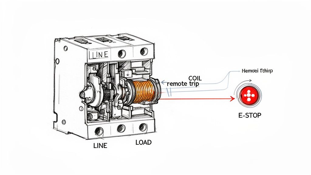
Inside that familiar breaker housing is a small solenoid coil, completely separate from the main current path. This coil just sits there, dormant, until it sees its specific control voltage. The moment that voltage hits, the solenoid actuates a mechanism that physically shoves the breaker's internal trip bar, opening the main contacts and cutting the power.
The magic is in that separation. You have the high-power work circuit and the low-power control circuit living side-by-side but acting independently.
The Role of the Control Circuit
Think of the control circuit as the brains of the operation. It's a completely isolated electrical path that does one thing and one thing only: tells the shunt trip coil when to fire. Typically, this circuit gets its power from a dedicated control power transformer, keeping it clean and separate from the main load.
So, what tells the control circuit to act? It’s usually a pilot device wired in series.
In the real world, this could be:
- Emergency Stop (E-Stop) Buttons: Those big red buttons you see plastered all over machinery for immediate, manual shutdown.
- Fire Alarm System Relays: A signal from the building's fire panel can automatically trip breakers to de-energize equipment, preventing it from fueling a fire or creating other hazards.
- Process Control Interlocks: Imagine a sensor on a machine guard. If an operator opens the guard while the machine is running, the interlock trips the breaker, protecting them from moving parts.
It all boils down to a simple but powerful principle: applying power to the small control circuit removes power from the big main circuit. Get that relationship straight, and you’re halfway to a safe and correct installation.
Before we dive into the specific components, here's a quick reference table to keep the key players straight.
Shunt Trip Breaker Core Components and Functions
| Component | Function | Importance in Wiring |
|---|---|---|
| Circuit Breaker | Provides standard overcurrent and short-circuit protection for the main power circuit. | This is the main device being controlled. Your main power lines (line/load) connect here as usual. |
| Shunt Trip Coil | An internal solenoid that, when energized, mechanically trips the breaker mechanism. | This is where your control circuit connects. It has dedicated terminals, often labeled, that must receive the correct control voltage. |
| Control Power Source | A separate, often low-voltage (e.g., 24VDC or 120VAC) source to power the control circuit. | You must wire from this source, not by tapping off the main breaker's line or load side, to maintain isolation. |
| Pilot Device | A switch or relay (like an E-Stop button or PLC output) that completes the control circuit. | This is the trigger. It's wired in series between the control power source and the shunt trip coil. |
Understanding how these pieces fit together is the foundation for a successful wiring job.
Remote-trip technology has a long history, born from the need to manage massive electrical systems safely. Early standards for handling major faults were pioneered on projects like the 1935 Boulder Dam, which had to clear 2,500 MVA faults in just three AC cycles. While the tech has changed, the principle of remote intervention remains the same. For a deeper dive, check out our guide on what a shunt trip is.
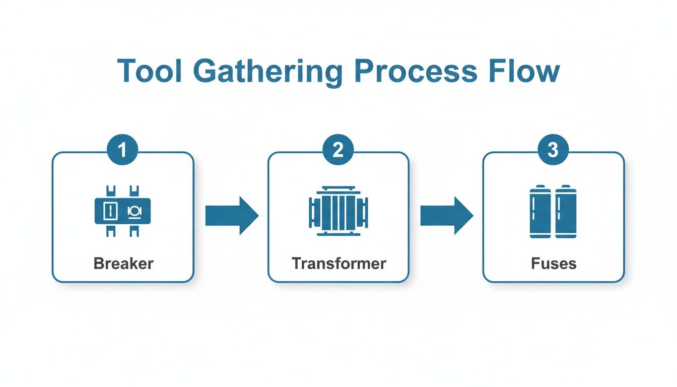
Getting Your Ducks in a Row: Tools and Parts for the Job
Any pro will tell you that a clean, safe, and code-compliant shunt trip installation starts long before you ever strip a wire. It begins right at the supply house counter.
This isn't the place to cut corners. Using the right parts, with the right ratings, isn't just "best practice"—it's a non-negotiable for keeping things safe and reliable.
The star of the show, of course, is the shunt trip circuit breaker. It needs to be a UL 489 listed device, and its amperage and voltage ratings have to match the main power circuit you're protecting. But here's a detail that trips people up: you absolutely must verify the shunt coil's voltage rating matches your control circuit (like 120VAC or 24VDC). A mismatch here will either burn out the coil instantly or it just won't work.
The Supporting Cast: Control Circuit Essentials
Once you have the breaker, you need to think about the rest of the control circuit. I’ve seen plenty of projects get derailed because all the focus was on the breaker itself, while these critical support components were treated as an afterthought. That's a recipe for headaches and potential safety hazards.
Here's what your shopping list should look like:
-
Control Power Transformer (CPT): This is what isolates your control circuit from the main power, stepping the voltage down to a much safer level. A classic rookie mistake is undersizing the CPT. The shunt coil itself doesn't draw much power once it's settled, but that initial inrush current when you hit the button is a whole different story. An undersized CPT will cause the voltage to sag, which can make the coil chatter or just plain fail to trip the breaker.
-
Fuses and Fuse Holders: Under UL 508A, you need fuses on both the primary and secondary sides of the CPT. We almost always reach for Class CC time-delay fuses for this. If you grab a fast-acting fuse by mistake, you’ll be chasing nuisance trips caused by the transformer's own inrush current.
-
Pilot Devices: This is whatever you're using as a trigger—an E-stop button, a relay contact from a fire alarm panel, or a PLC output. Just make sure the device's contacts are actually rated for the voltage and current you're running through them.
-
Control Wire: For wiring inside a control panel, 18 AWG MTW (Machine Tool Wire) is the gold standard. If your run has to leave the panel and go through conduit, you'll need to switch to THHN/THWN wire, sized correctly for the distance and load.
My Two Cents: Always, and I mean always, buy a CPT with a VA rating at least 25% bigger than your calculated continuous load. That little bit of buffer easily handles the inrush kick from the shunt coil and anything else on the circuit, saving you a world of trouble later.
Finally, you need a proper home for all these components. The enclosure you pick depends entirely on the environment. A simple NEMA 1 box is fine for a clean, dry control room, but you’ll need something like a NEMA 4X for a washdown area. If you want to dive deeper, you can learn more about picking the right types of electrical boxes to make sure your setup is protected and compliant.
With this bill of materials in hand, you're ready to build a circuit that’s not just functional, but robust and safe for the long haul.
Wiring Your Shunt Trip Circuit: A Practical Walkthrough
Alright, you’ve got your components picked out. Now it's time to put it all together and build a solid, reliable circuit. We're going to walk through a classic industrial setup: creating a dedicated control circuit to remotely trip a main breaker. The focus here is on getting the connections right and building in the safety checks that separate a professional job from a service call waiting to happen.
The whole process starts by creating a safe, isolated power source for your control logic. I always recommend tapping the line side of the main breaker to feed a dedicated Control Power Transformer (CPT). This is a critical detail because it ensures your control circuit stays electrically separate from the main power load and can still trip the breaker even if it's already open.
Building Your Control Power Source
First things first, find a good tap point on the incoming line-side conductors of the main breaker. This is non-negotiable. You need your control circuit to have power and be able to trip the breaker regardless of the breaker's own state. This tap is what will feed the primary side of your CPT.
Now, this isn't just about slapping on a couple of wires. You absolutely must install correctly rated primary fuses between that line-side tap and the CPT. Don't skip this. It’s a cornerstone of UL 508A compliance and is what protects that expensive transformer from any upstream faults.
Next up is the secondary side of the CPT. Just like the primary, this side needs its own fuse. In my experience, this secondary fuse is even more important because it’s what protects all your small-gauge control wiring and the delicate shunt trip coil from an overcurrent situation. A short in your control wiring shouldn't cause a fire; it should simply blow this fuse. That's the goal.
Wiring the Control Circuit Logic
With a clean, protected control power source ready to go, we can get into the "brains" of the operation. This is where we run the energized control wire through all your pilot devices—E-stops, sensors, alarm contacts—in series before it finally makes its way to the shunt trip coil.
The path is pretty straightforward when you break it down:
- One leg from the CPT's secondary fuse heads out to the first pilot device, like an Emergency Stop button's normally closed contact.
- The wire coming off that device then feeds the next device in the chain, maybe a normally open contact from a fire alarm relay.
- You just keep daisy-chaining like this until you've looped through every device in your series.
The wire leaving that very last pilot device is the one you’ll land on one of the shunt trip coil terminals. To complete the circuit, the other shunt trip terminal connects directly back to the neutral or common side of your CPT's secondary. The beauty of this series setup is that any single device in the chain can open the circuit and fire that trip coil.
A Word of Warning: The shunt trip coil is built for a momentary jolt of power, nothing more. If you apply continuous voltage, you will burn it out, often in less than a second. Your control logic has to be designed to ensure that coil only gets energized for the split-second it takes to do its job.
It’s amazing to think how far we’ve come since Square D's QO breaker changed the game in 1955. These modern breakers have highly integrated safety mechanisms. The solenoid actuator is ganged right to the main breaker mechanism, ready to be triggered by a signal from a fire alarm or other device. In fact, UL 489 requires these breakers to prove their reliability by tripping at 135% of their rated current within an hour. You can read up on some of the history of these advancements over at Plant Engineering.
Landing the Final Connections
We're in the home stretch. The last step is to connect the control wires to the shunt trip accessory itself. On the breaker, you'll find two dedicated terminals, often marked "S1" and "S2" or clearly shown in the manufacturer's diagram. These are the only two spots your control circuit should touch.
Once your wires are landed, stop and do a final check. I can't stress this enough. Tug on every connection to make sure it's tight. Look for stray wire strands that could cause a short. Most importantly, verify your series logic is correct: all your E-stops and other "off" switches should be normally closed, while your "trip" signals (like a fire alarm) should use normally open contacts that close when activated. Taking a few extra minutes here will save you hours of frustrating troubleshooting later.
Navigating Safety Protocols and Code Compliance
Look, getting a circuit to work is one thing. Making it safe, reliable, and up to code? That's what separates the pros from the amateurs. This is where we move beyond just "making it work" and focus on making it right.
Sloppy work or ignoring these guidelines isn't just bad practice—it's a massive liability waiting to happen. When you're wiring a shunt trip breaker, two big players dictate how you do the job: the National Electrical Code (NEC) and UL 508A for industrial control panels.
Understanding Key NEC and UL 508A Rules
Think of the NEC as the rulebook for all electrical installations in the US. For what we're doing, NEC Article 725, which covers remote-control and signaling circuits, is your go-to reference. It spells out exactly how your control circuits need to be installed and protected.
If that shunt trip breaker is going into an industrial control panel, then UL 508A is your bible. This standard gets incredibly granular, detailing everything from how far apart components need to be for proper cooling to the minimum wire bending radius so you don't stress the terminals. And that clear, permanent labeling on every wire and component? Not a suggestion. It’s a hard requirement for a compliant panel.
A critical point from UL 508A is the absolute mandate for control circuit protection. This is precisely why we install primary and secondary fusing on the control power transformer. It’s not just a good idea; it’s a core safety requirement to protect everything downstream from a fault.
Prioritizing Practical On-the-Job Safety
Code books are essential, but what keeps you safe in the field is disciplined, hands-on procedure. Before you even think about putting your hands inside a panel, a strict Lockout/Tagout (LOTO) process must be followed. This is more than just flipping a breaker; it’s a formal system to guarantee that a machine is completely de-energized and can't be started up by accident.
Here's what that looks like in the real world:
- Verify Zero Energy: Always use a properly rated multimeter to test for voltage at every single connection point before you touch anything. Never, ever just assume a breaker is off. That's a rookie mistake that can have serious consequences.
- Use Insulated Tools: Your screwdrivers, wire strippers, and pliers should all be properly insulated. This is a crucial layer of defense against any stray voltage or overlooked energized parts.
The technology inside the breakers themselves has also come a long way in making our jobs safer. The move from old-school thermal-magnetic trip units to modern electronic ones was a huge leap forward. In fact, research between 1980 and 2000 showed an incredible 70% drop in common-cause failures for circuit breakers, especially in fail-to-open situations. You can learn more about the evolution of molded case circuit breakers to see how far we've come.
Knowing your gear is half the battle. To make sure you're starting with the right component for the job, check out our guide on correct circuit breaker sizing.
Testing and Troubleshooting Common Wiring Issues
A clean wiring job is a great start, but you're not done until you’ve proven the circuit is rock-solid. Commissioning is where you catch the small stuff before it becomes a big problem on the plant floor. This isn't a race; it's a methodical process to validate your work.
First things first: commission the control circuit with the main breaker locked out. After your LOTO is in place, go ahead and energize the control power transformer only. Grab your multimeter and confirm you’ve got the correct voltage on the secondary side of the CPT.
Next, trigger your pilot devices one by one. You should hear a distinct click from the shunt trip mechanism inside the breaker. That sound is your confirmation that the control logic works, all without sending a single amp downstream.
Once you’ve passed that bench test, it’s time for a live one. With the area clear, close the main breaker and send the trip signal. That breaker should open instantly. No hesitation.
Identifying and Solving Common Problems
Even the most careful installs can have hiccups. I’ve been on enough service calls to know that most issues boil down to a few common culprits. Knowing what to look for can turn a major headache into a quick fix.
The classic mistake? The breaker trips the second you try to close it. This is almost always a sign that the shunt trip coil is being continuously energized. This usually happens when a pilot device, like an E-stop button, is wired normally-open instead of normally-closed. That coil isn't built for continuous duty and will burn out fast. You need to fix that logic immediately.
Another common one is a breaker that just won't trip when commanded. Nine times out of ten, that points to an open circuit somewhere in your control wiring.
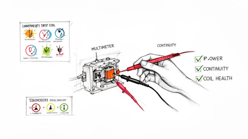
Field Tip: When a shunt trip circuit fails, start your diagnosis at the coil itself. A quick continuity check with a multimeter will tell you instantly if the coil has fried. If it ohms out okay, you know the problem is somewhere in your control wiring or power source.
Having a good handle on general troubleshooting and replacing electrical components is a huge asset for any technician and provides a solid foundation for these skills.
Common Shunt Trip Wiring Problems and Solutions
When you're staring at a circuit that isn't behaving, it's easy to get tunnel vision. This table breaks down the most frequent issues I've seen in the field, pointing you directly to the likely cause and how to get it sorted out.
| Symptom | Likely Cause | How to Fix |
|---|---|---|
| Breaker trips immediately upon closing | Shunt coil is continuously energized due to incorrect pilot device wiring (e.g., NO contact used instead of NC). | Correct the control circuit logic. Ensure pilot devices provide only a momentary signal to the coil upon activation. |
| Breaker fails to trip when commanded | 1. Blown control fuse. 2. Open in the control wiring. 3. Faulty or burned-out shunt coil. |
1. Check and replace the secondary fuse. 2. Check wiring continuity from the CPT through each pilot device. 3. Test coil for continuity; replace the shunt trip accessory if open. |
| Nuisance tripping | Control circuit voltage is unstable, or there are momentary voltage spikes from nearby inductive loads. | Ensure the CPT is properly sized and not overloaded. Consider adding a surge suppressor or control relay to buffer the shunt coil from noise. |
Keep this diagnostic chart handy. Following a logical troubleshooting path saves time and prevents you from chasing ghosts in the machine.
Frequently Asked Questions About Shunt Trip Wiring
Even when you’ve got a solid set of drawings, questions always pop up out in the field. Let's dig into some of the most common things we hear from engineers and integrators wrestling with shunt trip breaker wiring.
Getting these little details right is what separates a safe, reliable installation from a future service call.
Can I Use Any Voltage For The Shunt Trip Coil?
Absolutely not. This is one of those things you have to get exactly right. The voltage rating on the shunt trip coil is a hard spec, not a friendly suggestion. These coils are precision-wound for a very specific voltage, like 120VAC or 24VDC.
If you hit it with too much voltage, you'll fry the coil in an instant—sometimes with a nice puff of smoke. If the voltage is too low, the coil just won't generate enough magnetic oomph to physically kick the trip mechanism.
Always, always double-check the manufacturer's data sheet. Your control power source has to be a perfect match.
What’s The Difference Between A Shunt Trip And An Undervoltage Release?
I see this one trip people up all the time, but the distinction is critical for safety. They're basically opposites in how they operate.
-
A shunt trip is an active device. It needs you to apply voltage to make the breaker trip. Think of it as a "push-to-trip" system. This makes it perfect for things like emergency stop circuits where you want a deliberate, positive action to shut things down.
-
An undervoltage release (UVR) is more of a passive, failsafe device. It needs a constant "hold-in" voltage to keep the breaker closed. The second that power disappears, it trips. This is your go-to for preventing equipment from unexpectedly restarting after a power outage, which could be a massive safety hazard.
The bottom line is this: a shunt trip gives you a commanded shutdown, while a UVR gives you an automatic shutdown when control power is lost. Choosing the right one is all about the safety requirements of your specific machine.
Is Fusing The Control Circuit Really Necessary?
Yes, and it’s completely non-negotiable. Fusing the control circuit is a mandatory safety requirement under both NEC Article 725 and UL 508A for industrial control panels. It’s there for two very important reasons.
First, it’s protecting the small-gauge control wiring itself from an overcurrent situation. A short circuit in a control wire without a fuse could easily cook the insulation and spark a fire. Second, it protects the delicate shunt trip coil. A fault condition could destroy that coil in a heartbeat.
A properly sized fuse on the secondary side of your control power transformer is your first and best line of defense. Don't skip it.
At E & I Sales, we live and breathe this stuff, designing and building reliable, code-compliant UL control panels for all kinds of industrial applications. If you need a hand specifying the right components or figuring out how to integrate a shunt trip circuit into your system, our team is here to help. Explore our custom control solutions at https://eandisales.com.