
Sizing a motor starter isn't just about matching a few numbers on a spec sheet. It’s about creating a perfect partnership between your motor and its protective device, ensuring everything runs smoothly, safely, and without costly interruptions. You're selecting a contactor and overload relay that can handle the raw power of motor startup and the long haul of daily operation, all while standing guard against electrical faults.
Get this right, and you’ve built in protection and reliability. Get it wrong, and you’re looking at fried equipment and unscheduled downtime.
Why You Can't Afford to Guess on Starter Sizing
Before we jump into the nitty-gritty of charts and calculations, let's talk about why this is one of the most critical tasks for any plant engineer or control packager. A motor starter is more than a simple on/off switch; it’s the motor's bodyguard.
Think of it as a two-part system. First, you have the contactor, the heavy-lifter that makes and breaks the high-current circuit needed to get the motor spinning. Then you have the overload relay, the vigilant watchdog that monitors the current. If the motor starts drawing too much power for too long, the overload relay steps in and trips the circuit, saving the motor from a slow, expensive death by overheating.
The Bedrock of a Safe, Compliant System
Every choice you make here is guided by standards, with the National Electrical Code (NEC) being the law of the land. Specifically, NEC Article 430 lays out the rules of the road for everything from conductor sizes to overload protection. Following these rules isn’t just good practice—it’s mandatory for creating safe installations that protect your people and your machinery.
This process chart shows the foundational thinking that needs to happen before you even touch a calculator.

It’s a simple but powerful reminder: start with accurate data and a clear understanding of the standards you need to meet.
The Big Decision: NEMA vs. IEC
Early on, you'll face a fork in the road. Will you go with NEMA or IEC standards? They both get the job done, but they have very different philosophies.
- NEMA (National Electrical Manufacturers Association) starters are the classic North American workhorses. They're built tough, sized conservatively based on standard horsepower ranges, and can take a beating.
- IEC (International Electrotechnical Commission) starters are the more modern, "Euro-style" choice. They’re compact, often more cost-effective, and demand a precise sizing approach based on the motor's exact current draw and application details.
This choice dictates everything from how much space you need in the panel to how deep you need to go with your calculations. It’s no surprise that the demand for these components is surging. The global motor starter market jumped from USD 7.4 billion to USD 7.8 billion in just one year and is on track to hit over USD 12 billion by 2034. That growth is a testament to how critical proper motor control is in today’s industrial world.
Key Takeaway: Sizing a motor starter is a strategic engineering decision, not just a technical task. It directly impacts your facility's uptime, the lifespan of your equipment, and overall safety. A miscalculation can easily lead to nuisance trips, motor failure, and a major hit to your bottom line.
Quick Sizing Checklist Overview
To keep things straight, here’s a high-level look at the steps we'll be walking through. This table outlines the critical actions you'll take at each stage of the sizing process, ensuring nothing gets missed.
| Sizing Step | Key Action | Governing Standard |
|---|---|---|
| Gather Motor Data | Record motor nameplate HP, voltage, FLA, and Service Factor. | NEC Tables / Manufacturer Data |
| Determine FLA | Use nameplate FLA if available; otherwise, use NEC tables. | NEC Article 430 |
| Apply Derating Factors | Adjust for high ambient temperatures and altitudes. | NEMA / IEC Standards |
| Select Overload Relay | Set the trip current based on motor FLA and Service Factor. | NEC 430.32 |
| Choose Contactor/Starter | Select a starter rating that meets or exceeds the motor HP. | NEMA ICS 2 / IEC 60947 |
| Verify Coordination | Ensure proper short-circuit protection and coordination. | UL 60947-4-1 / NEC 430.52 |
Following this structured approach turns a potentially complex task into a manageable and repeatable process, giving you confidence in your final selection.
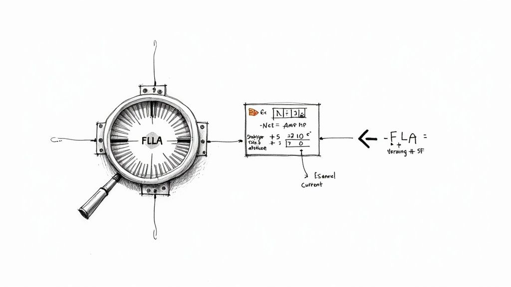
Before you can even think about picking out hardware, you need to nail down one absolutely critical number: the motor’s Full-Load Amps (FLA).
Everything that follows—the overload relay, the contactor, the short-circuit protection—is based on this value. It’s the current the motor is designed to pull when it’s running at its rated horsepower, and getting it wrong is a recipe for disaster.
Start with the Nameplate FLA
The first place you should always look for the FLA is right on the motor's nameplate. This is the manufacturer's certified data, your ground truth for that specific piece of equipment. You'll usually find it listed right alongside the horsepower (HP), voltage, and phase.
But we’ve all been there. You get out to the floor, and the nameplate is covered in 20 years of paint, corroded beyond recognition, or just gone. Now what?
This is when you turn to the industry’s trusted backup plan: the National Electrical Code tables. For a three-phase motor, you'll want to pull up NEC Table 430.250. This table gives you a standardized FLA based on horsepower and voltage. It's important to know that these values are intentionally a bit conservative—often higher than the actual nameplate FLA—to account for swings in motor efficiency and power factor. That built-in safety margin makes them a solid, reliable substitute when you can't read the nameplate.
A Critical Distinction: NEC 430.6(A) lays out a rule that trips people up all the time. You must use the NEC table values for sizing your wires (conductors) and your short-circuit protection (fuses or breakers). But for setting the overload relay, you must use the actual nameplate FLA. This little detail is key to preventing nuisance trips while still making sure your wiring can handle the load.
Adjusting for Real-World Conditions
A motor's nameplate rating assumes it’s operating in a perfect lab—usually at sea level and a comfortable 40°C (104°F). Your plant is probably not a perfect lab. That's where derating factors come in.
Two big environmental factors can make a motor work harder and pull more current than expected:
- High Ambient Temperature: If a motor is running in a space hotter than its 40°C design rating, it can't cool itself effectively. To keep from burning up, its effective horsepower has to be reduced, or "derated."
- High Altitude: Ever try to catch your breath at high elevations? Motors feel it, too. At altitudes above 3,300 feet (1,000 meters), the air is thinner and less effective at cooling. This also forces a derating.
These factors stack. A motor in a hot facility located high in the mountains is going to need a significant adjustment.
Don't Forget the Service Factor
The last piece of the puzzle is the Service Factor (SF), another value you'll find on the nameplate. Think of the Service Factor as a built-in "overload" capacity that the motor can handle for short bursts without damage.
- A standard motor typically has an SF of 1.15.
- Many newer energy-efficient motors have an SF of 1.0.
An SF of 1.15 means the motor can safely handle a load 15% greater than its rated horsepower. This is hugely important when setting your starter's overload protection. Per NEC 430.32, you can set the overload trip point up to 125% of the nameplate FLA if the motor has an SF of 1.15 or more. If the SF is 1.0, your maximum setting drops to 115%. For a good visual breakdown, this NEMA motor starter sizing chart is a handy reference.
Let’s walk through a quick, practical example.
Say you've got a 25 HP, 460V, 3-phase motor with this data on the nameplate:
- FLA: 32 Amps
- Service Factor: 1.15
To figure out the maximum current you can allow before the overload trips, you just do a simple calculation:
32A (FLA) x 1.25 (for SF ≥ 1.15) = 40 Amps
This tells you to select an overload relay that has 40A within its adjustable range. By setting it correctly, you're giving the motor the protection it needs without causing frustrating shutdowns when it's just doing its job within that service factor buffer. This calculated value—your design current—is what you’ll use to select the rest of your starter components.
Matching Overloads and Contactors to Your Motor
Alright, with your motor’s design current nailed down, we can get into the heart of the starter itself: the overload relay and the contactor. These two components are the workhorses, providing the protection and control your motor needs to live a long, productive life. Getting this pairing right is absolutely critical.
First up is the overload relay. Think of it as your motor's bodyguard, protecting it from thermal damage. The idea here is simple: you need to pick a relay with an adjustable current range that neatly brackets your motor's nameplate FLA. This gives you the wiggle room to dial in the perfect trip setting.
According to NEC 430.32, the rules for setting it are pretty clear:
- For motors with a Service Factor of 1.15 or higher, you can set the overload up to 125% of the nameplate FLA.
- For motors with a Service Factor of 1.0, the ceiling is a bit lower at 115% of the nameplate FLA.
That small distinction is important. It ensures the motor is protected from slow-burning overcurrents but still has the breathing room to handle brief periods of hard work within its designed service factor.
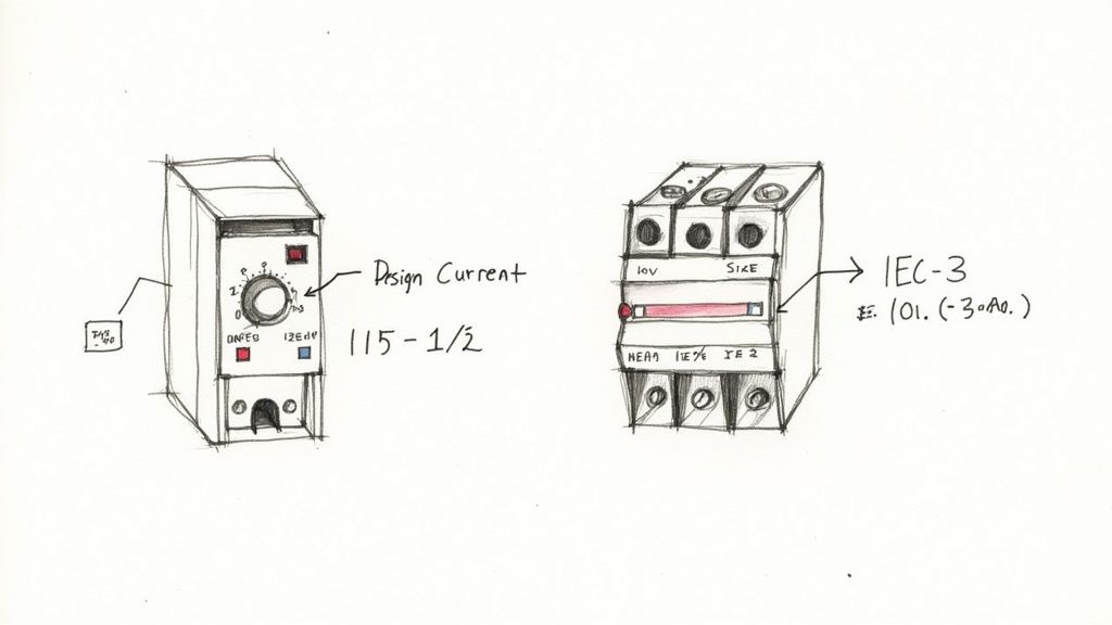
Selecting the Right Contactor: NEMA vs. IEC
Now for the contactor—the heavy-duty switch that takes the punch of inrush current every time the motor kicks on. How you choose this component depends entirely on whether you're working with NEMA or IEC standards. They're two completely different philosophies.
If you're looking for a deep dive, Kent Electrical Supply has a great guide on selecting the perfect contactor that covers a lot of ground for industrial work.
NEMA Starters: The Simple Powerhouse
NEMA sizing is all about being straightforward and tough. You don't mess around with fine-tuned amperage calculations. Instead, you just match the motor's horsepower and voltage to a standard NEMA size. It's that easy. For example, a 25 HP motor running at 460V is a textbook NEMA Size 2. These starters are built like tanks with a generous safety margin, making them incredibly robust and forgiving in the field.
IEC Starters: The Precision Instrument
IEC sizing, on the other hand, demands more precision. You don't use broad horsepower ranges. Instead, you select an IEC contactor based on its exact amperage rating and its utilization category. For the vast majority of motor jobs (starting and stopping standard squirrel-cage motors), you'll be looking for an AC-3 rating. The rule is simple: the contactor's AC-3 amp rating must be higher than the motor's design current you calculated earlier. Of course, knowing how to wire them correctly is just as important; our guide to the three-phase motor wiring diagram can give you some valuable context here.
Here’s a pro tip from the field: always consider the motor's duty cycle when picking an IEC contactor. If a motor is starting, stopping, or reversing constantly—think jogging or plugging duty—that falls under the more severe AC-4 category. An AC-3 rated contactor will burn out fast in that scenario. You’ll need to either grab a contactor specifically rated for AC-4 or significantly upsize your AC-3 unit to handle the abuse.
NEMA vs IEC Starter Sizing Approach
The decision between NEMA and IEC often comes down to the demands of the application, how much panel space you have, and your budget. This table breaks down the fundamental differences in how you size them.
| Characteristic | NEMA Starters | IEC Starters |
|---|---|---|
| Sizing Basis | Horsepower and Voltage | Amperage and Utilization Category |
| Design Philosophy | Robust, conservative, built-in safety margin | Precise, application-specific, compact |
| Selection Process | Match HP/Voltage to NEMA Size (0, 1, 2, etc.) | Match motor current to contactor's AC-3 rating |
| Best For | Heavy-duty applications, simplicity | OEM equipment, space-constrained panels |
At the end of the day, both approaches get the job done, but they get there from different directions. NEMA prioritizes ruggedness, while IEC focuses on precision and efficiency.
While we've focused on traditional across-the-line starters, it's worth noting the industry is changing. Soft starters have become the fastest-growing part of the market, accounting for USD 2.12 billion recently. That segment is set to grow at an accelerated 8.7% clip through 2030, showing a real shift in priorities. This isn't just about starting motors anymore; it's about saving energy, reducing mechanical wear and tear, and connecting equipment to the IIoT. Sizing today is as much about optimizing performance as it is about pure protection.
Ensuring Proper Short-Circuit Protection
While your overload relay is the motor's bodyguard against slow-burn thermal damage, it's completely outmatched by the sudden violence of a short circuit. For that, you need a dedicated Short-Circuit Protective Device (SCPD), which is almost always a fuse or a circuit breaker.
Getting this component right isn't just a good idea—it's a critical safety mandate. It's what stands between you and catastrophic equipment failure, arc flash, and fire.
Your first step is to figure out the Available Fault Current (AFC) right at the installation point. This is the absolute maximum current that could flow during a dead short, a value determined by things like the utility transformer's size and how far away it is. If you don't have this number from an engineering study, you absolutely need to get it calculated. Without it, you're just guessing.
Choosing the Right SCPD
Your chosen SCPD must have an Interrupting Rating (IR) that is equal to or, even better, greater than the AFC. If your system can produce 15,000 amps of fault current, a breaker rated for only 10,000 amps is an accident waiting to happen. The SCPD is your last line of defense, and its ability to handle the worst-case scenario is non-negotiable.
Once you know the required IR, you can size the SCPD’s trip rating based on the motor's Full-Load Amps (FLA), following the guidelines in NEC Article 430.52. The code provides different multipliers for different types of SCPDs:
- Non-Time-Delay Fuses: Can be sized up to 300% of the motor FLA.
- Dual-Element (Time-Delay) Fuses: Capped at 175% of the motor FLA.
- Instantaneous Trip Breakers: Allowed up to a whopping 800% of motor FLA.
- Inverse Time Breakers: Limited to 250% of motor FLA.
These multipliers are carefully calculated to let the harmless inrush current of a motor starting up pass by without a nuisance trip, while still reacting instantly to a legitimate, dangerous short circuit.
The Importance of Coordination
This is where I see a lot of installations fall short. It's not enough to just grab a starter and an SCPD off the shelf; they must be tested and listed to work together. This is what we call coordination. Manufacturers publish tables showing exactly which fuses or breakers have been tested with their starters to ensure they operate as a safe, predictable system during a fault.
A key concept here is the difference between UL Type 1 and Type 2 coordination. Type 1 protection means the fault is cleared safely (no explosion), but the starter is probably toast and needs replacing. Type 2 protection also ensures safety, but the starter will be reusable after the fault. For any critical application, always aim for Type 2 coordination. It drastically reduces downtime and replacement costs.
Properly coordinated protection of motors is a complex but vital aspect of electrical design.
A Final Compliance Check
Think of this as your final pre-flight check. Before you sign off, you have to verify the entire assembly—motor, starter, and SCPD—is fully compliant. This means double-checking that the starter's own Short-Circuit Current Rating (SCCR) is high enough for the installation point and that your SCPD is one of the specific models the manufacturer listed for achieving that rating.
This is especially true when you consider the global picture. The Asia-Pacific region, for instance, now represents over 40% of the global motor starter market, driven by huge infrastructure projects. Meanwhile, in North America, the market—valued at USD 1.87 billion recently—is more focused on specialized enclosed starters for advanced automation. This shows that proper sizing isn't just about local codes, but also the specific demands of the industrial environment you're working in.
By meticulously verifying your short-circuit protection and coordination, you turn a collection of individual parts into a truly safe and reliable motor control system.
Real-World Examples and Common Sizing Mistakes

Theory gets you to the starting line, but knowing how to apply it in the real world is what wins the race. Let's walk through the entire process with a couple of common scenarios you'll definitely encounter. Seeing the numbers in action is the best way to make it all click.
After that, we’ll dive into the most common—and costly—errors I see engineers and technicians make in the field. Trust me, avoiding these pitfalls is just as crucial as knowing the right steps in the first place.
Example 1: The Standard NEMA Starter
Let's kick things off with a classic industrial application: a conveyor motor humming away in a climate-controlled facility. This is about as straightforward as it gets, making it a perfect job for a rugged, no-nonsense NEMA starter.
Motor Details:
- Power: 25 HP
- Voltage: 460V, 3-Phase
- Nameplate FLA: 32 Amps
- Service Factor (SF): 1.15
- Environment: 25°C (77°F) at sea level (so no derating needed)
First up, the overload setting. Since this motor has a 1.15 SF, the NEC allows us to set the overload up to 125% of the nameplate FLA. The math is simple: 32A x 1.25 = 40A. Our job now is to find an overload relay with an adjustable range that includes 40A.
Next, we pick the NEMA starter size. A quick look at any standard NEMA sizing chart shows a 25 HP motor at 460V falls squarely into the NEMA Size 2 category. A Size 2 starter is rated for this exact job and has a continuous current rating of 45A, giving us plenty of headroom. This kind of simplicity is the real beauty of the NEMA system.
Example 2: The Precision IEC Starter
Now for something a little more nuanced. We've got an IEC starter for a pump, but it's located in a pretty tough environment. This is where precision and careful calculation become critical.
Motor Details:
- Power: 15 HP
- Voltage: 460V, 3-Phase
- Nameplate FLA: 19 Amps
- Service Factor (SF): 1.0
- Environment: 50°C (122°F) ambient temperature (derating is a must)
That high ambient temperature is the key detail here. Most IEC starters are rated for a comfortable 40°C, so we absolutely have to derate the contactor's capacity. Pulling up the manufacturer’s derating chart, we see that at 50°C, we need to reduce the contactor's current rating by 10%.
The motor is running a standard pump, which calls for an AC-3 utilization category contactor. To handle the 19A FLA after that derating, our contactor needs a normal rating of at least 19A / 0.90 = 21.1A. We'd then select the next standard size up, which is likely a 25A AC-3 rated contactor.
For the overload, the motor's 1.0 SF means we're limited to a 115% setting. That works out to 19A x 1.15 = 21.85A. We'll need to choose an electronic overload relay whose adjustment range covers that 21.85A setpoint.
Expert Insight: Environmental factors are, without a doubt, the most overlooked part of sizing an IEC starter. Always, always check the ambient temperature and altitude against the manufacturer’s spec sheet. A starter that works flawlessly in a 20°C air-conditioned room can become a chronic source of nuisance trips in a 50°C boiler room if it isn't properly derated.
Top Mistakes to Avoid When Sizing a Starter
Knowing the right steps is half the battle. Knowing what not to do will save you from expensive rework, damaged equipment, and frustrating downtime. Here are the most frequent errors I run into on the job.
1. Ignoring the Service Factor
This is probably the most common slip-up: applying a blanket 125% overload setting without looking at the motor's service factor. Many modern, high-efficiency motors come with an SF of 1.0, which means the NEC strictly limits the overload setting to 115% of FLA. Go higher, and you've just left your expensive motor under-protected.
2. Miscalculating Environmental Effects
As we saw in the IEC example, heat and altitude aren't just suggestions on a datasheet; they are hard physical limits that choke a starter's capacity. Failing to apply derating factors for conditions outside the standard (typically 40°C and 3,300 ft) is a surefire recipe for premature failure and nuisance tripping.
3. Choosing the Wrong Overload Trip Class
Most off-the-shelf starters come with a standard Trip Class 20 overload. This means it will trip in 20 seconds when the current is 600% of its setting. But what about a high-inertia load like a massive centrifugal fan that takes a while to get up to speed? That Class 20 will likely cause nuisance trips on startup. You need a Trip Class 30 to give the motor enough time to accelerate without tripping.
4. Failing to Verify Short-Circuit Coordination
Just because your fuse, breaker, and starter are all individually rated for the job doesn't guarantee they'll play nice together during a short circuit. This is a huge safety issue. You must consult the starter manufacturer’s published tables to select a specific SCPD (short-circuit protective device) model that has been tested and listed for use with that starter. This is the only way to achieve a certified SCCR (Short-Circuit Current Rating) and is non-negotiable for safety and code compliance.
Frequently Asked Questions About Sizing Motor Starters
Even after you’ve got the basic process down, the real world has a knack for throwing curveballs. When you're standing in front of a panel, a few specific questions always seem to come up. Let's tackle some of the most common ones I hear from engineers and technicians in the field.
What Happens If I Use the Wrong Starter Size?
Getting the starter size wrong is a guaranteed headache, but how it goes wrong depends on whether you undersize or oversize it.
An undersized starter is an immediate fire drill—sometimes literally. The contacts and overload relay simply aren't built to handle the motor's full-load amps (FLA). You're almost certain to see nuisance tripping right away, followed by rapid overheating and premature failure. It's a genuine safety hazard.
On the other hand, a grossly oversized starter introduces a more subtle, but equally destructive, problem. The overload relay's adjustment range will be so high that you can't dial it in to accurately protect the motor. This creates a massive protection gap where a minor but persistent overload condition can go completely unnoticed, slowly cooking the motor windings over weeks or months until it fails.
Can I Use an IEC Starter Instead of a NEMA Starter?
You absolutely can, but you have to play by their rules. These two types of starters come from different design philosophies, and you can't just treat them as interchangeable.
NEMA starters are the North American workhorses—big, rugged, and sized into broad horsepower categories. IEC starters are more compact, application-specific, and demand precise sizing based on the motor's exact current draw and duty cycle.
If you're making a switch:
- Going from NEMA to IEC: You'll need to do your homework. Calculate the motor's precise design current and select an IEC contactor with an AC-3 rating that comfortably exceeds it.
- Going from IEC to NEMA: This is much simpler. You just match the motor's horsepower and voltage to the corresponding NEMA size (e.g., NEMA Size 1, Size 2). It's a far more forgiving process.
How Do I Size a Starter for a Motor with No Nameplate?
It happens more often than you'd think—a motor's nameplate is either painted over, corroded, or just plain missing. When this happens, your best friend is the National Electrical Code (NEC). Your starting point is Article 430.
For a standard three-phase motor, you'll use NEC Table 430.250. This gives you a standardized Full-Load Current (FLC) value based on the motor's horsepower and voltage.
This is a critical distinction: The NEC requires you to use these table values for sizing your conductors and short-circuit protection. But for setting the overload relay, you're supposed to use the actual nameplate FLA. When the nameplate is gone, using the NEC table value is a safe, conservative fallback, but be aware it might cause nuisance trips if you're dealing with a modern, high-efficiency motor.
Do I Always Need to Derate for Temperature and Altitude?
Not always, but you always need to check if it's required. It's a step you can't afford to skip.
Most standard starters are rated to perform perfectly up to a certain point, typically 40°C (104°F) and an altitude of 3,300 feet (1,000 meters). If your control panel is going into a boiler room, a sun-baked enclosure in Arizona, or a facility in the Rocky Mountains, you're likely exceeding those limits.
When you do, you must apply the manufacturer's derating factors. Ignoring this means the starter can't dissipate heat properly, which reduces its current-carrying capacity and sets it up for an early grave. Always have the manufacturer's data sheet handy.
What is the Difference Between Trip Class 10, 20, and 30?
The trip class on an overload relay is all about timing. It tells you how long the relay will wait before tripping when the motor is in a locked-rotor state, pulling roughly 600% of its normal current.
- Trip Class 10: Trips in 10 seconds or less. This is for light, easy-starting loads like small fans, blowers, or centrifugal pumps.
- Trip Class 20: Trips in 20 seconds or less. This is your standard, go-to class for the vast majority of general-purpose motor applications.
- Trip Class 30: Trips in 30 seconds or less. You need this for heavy, high-inertia loads that take a long time to get up to speed—think big flywheels, loaded conveyors, or rock crushers.
Picking the wrong class will either drive you crazy with nuisance trips at startup (if it's too fast) or fail to save your motor from a stall (if it's too slow).
Sizing a motor starter correctly is more than a technical exercise; it's a foundational skill for building safe, reliable systems. If you need a partner with deep expertise in motor controls and UL-listed panel packaging, E & I Sales has the experience to guide your project from specification to startup. Explore our solutions and see how we can help at https://eandisales.com.