
Think of Fault Current Indicators, or FCIs, as the smoke detectors for your electrical system. They don't stop a fault from happening—like a short circuit or a ground fault—but they instantly tell you exactly where the problem is. This cuts troubleshooting downtime from hours to minutes, which is absolutely critical for safety and keeping operations online.
The Critical Role of Fault Location
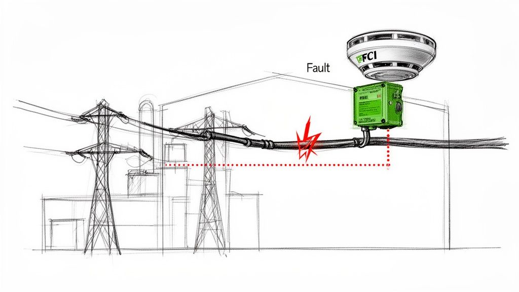
In any complex industrial plant or data center, an electrical fault is never a small hiccup. It's a direct threat to your entire operation. When a vital circuit trips, the real challenge isn’t just fixing it; it’s finding it in the first place.
Without FCIs, maintenance crews are stuck in a painful process of elimination. They have to manually hunt through breakers and feeders, one by one, trying to track down the source. This "hunt-and-peck" method can drag on for hours, leaving production lines dead in the water and costing thousands in lost revenue with every tick of the clock.
The longer a fault remains hidden, the higher the risk of other equipment getting damaged. This is where FCIs prove their worth, turning a long, frustrating search into a quick, targeted fix.
From Hours to Minutes
An FCI’s job is simple but powerful: provide a clear, impossible-to-miss signal right at the point of failure. This is usually a bright, flashing LED or a pop-up mechanical flag that immediately eliminates all the guesswork.
An FCI transforms a chaotic troubleshooting emergency into a controlled, directed response. Instead of your team asking, "Where do we even start looking?" they can see the faulted section instantly and get to work on isolation and repair.
This immediate visual cue empowers technicians to act fast. They can strategically bypass the affected circuit to get the rest of the facility back up and running while the repair is handled. This kind of tactical advantage is a cornerstone of modern electrical substation design and smart maintenance.
This isn't just a niche technology; it's a global standard. In recent years, over 1.2 million fault indicators were installed worldwide, a number that speaks volumes about their role in modernizing power grids. These devices can slash fault-finding time by up to 45%.
Core Functions of Fault Current Indicators
At their heart, FCIs do more than just point to a problem. They are a fundamental part of a system designed for safety, asset protection, and operational excellence. Here's a quick breakdown of what they do.
| Function | Primary Benefit | Impact on Operations |
|---|---|---|
| Fault Detection | Instantly identifies abnormal current surges from short circuits or ground faults. | Reduces the need for manual circuit testing, saving valuable technician time. |
| Visual Indication | Provides a highly visible local alert (LED, flag) at the fault location. | Allows maintenance staff to quickly pinpoint the exact feeder or cable that has failed. |
| Rapid Isolation | Enables faster isolation of the faulted circuit segment from the main system. | Minimizes the scope of the outage, keeping unaffected parts of the facility online. |
| Downtime Reduction | Drastically cuts the time required to locate and address electrical faults. | Boosts Overall Equipment Effectiveness (OEE) and maintains production schedules. |
Ultimately, integrating FCIs into your infrastructure is a proactive step toward a more resilient and efficient electrical system. They provide the clarity needed to keep small issues from turning into major operational disasters.
How Fault Current Indicators Actually Work
At its heart, a fault current indicator is a simple device built for a complex and critical job. Imagine it as a watchdog clamped onto a power cable, constantly monitoring the flow of electricity. Under normal conditions, this current hums along predictably.
But when a fault happens—like a dead short or a ground fault—the game changes in an instant. The current surges to many times its normal level, creating a massive, sudden spike. The FCI’s entire job is to see that specific event and raise an immediate, obvious alarm.
To pull this off, FCIs use some clever sensing technology that can pick up on these abrupt changes without ever making direct electrical contact with the live conductor. This non-invasive design is what makes them so safe and easy to install in tight, energized spaces.
Sensing the Surge
The real magic behind an FCI is its ability to measure the effects of electrical current from a safe distance. Two main technologies have become the go-to methods, each with its own way of spotting the tell-tale signs of a fault.
-
Magnetic Field Sensors: Every current-carrying wire generates a magnetic field. When a fault occurs, that massive spike in current creates an equally massive and instantaneous expansion of this magnetic field. These sensors are designed to react to that powerful change, tripping an alarm the moment the field strength blows past a preset threshold.
-
Rogowski Coils: A Rogowski coil is essentially a specialized, air-cored loop of wire that acts as a precision current transducer. Because it lacks a magnetic core, it can't get saturated by huge current spikes. This makes it incredibly good at measuring very fast-changing currents (high di/dt, or rate-of-rise) and, more importantly, distinguishing a real fault from a temporary inrush current, like when a big motor kicks on. If you want to dig deeper into what causes these events, we have a guide on what can cause a breaker to trip.
This diagram shows a Rogowski coil in action, measuring current and signaling a fault.
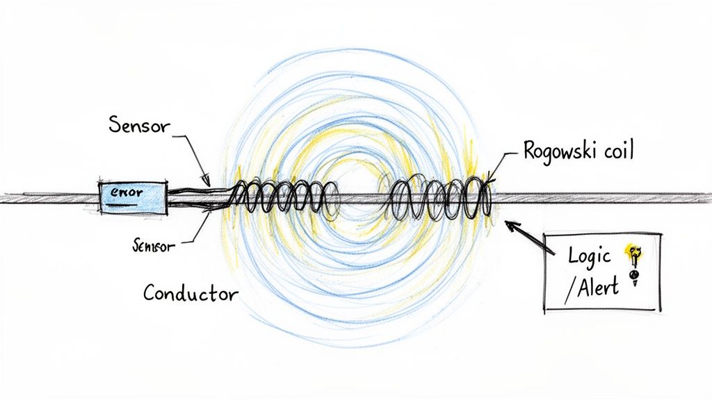
You can see the core parts at play: the coil wrapped around the conductor, the sensor that interprets its signal, and the logic that trips the alert. It’s an elegant solution for accurate fault detection without risky direct contact.
The Anatomy of an FCI
While the sensing tech might differ, the basic building blocks of most FCIs are pretty much the same. Knowing the parts helps you understand how they work together as a system.
A typical FCI is made of three key components:
- The Sensor: This is the part that actually clamps around the cable. It houses the magnetic sensor or Rogowski coil and is built tough enough to handle the harsh electrical and physical environment inside switchgear or motor control centers.
- The Logic Circuit: This is the brains of the operation. It takes the signal from the sensor, compares it against the programmed trip settings, and decides whether to sound the alarm. Good ones have built-in intelligence to ignore temporary inrush currents and prevent false alarms.
- The Indication System: This is the output—how the FCI tells you something is wrong. It could be a simple, bright flashing LED for a local visual cue, a mechanical flag that physically pops up, or a communication output that sends a signal to a remote SCADA system or PLC for centralized monitoring.
Powering the Watchdog
An FCI needs a reliable power source to stay on guard. The choice here usually comes down to the specific application and how easy it is to get to for maintenance.
Self-Powered FCIs: These are pretty ingenious. They draw all the power they need to operate directly from the magnetic field of the very conductor they're monitoring. This makes them completely self-sufficient—no batteries, no external wiring. They're a true "fit-and-forget" solution.
Battery-Powered FCIs: These units rely on long-life lithium batteries that can last 15 to 20 years. They're perfect for spots where the normal line current is too low to power a self-contained unit, or where you need more power for advanced communication features. Most modern units will even give you a low-battery warning, so you can swap it out long before it dies.
This flexibility in design means there's an FCI out there for just about any industrial environment you can throw at it.
Where to Put Fault Current Indicators for the Biggest Payoff
Knowing how fault current indicators work is one thing. Knowing exactly where to install them to save the most time and money? That’s the real trick. Their value skyrockets when you place them strategically across your industrial electrical system, like sentinels guarding your most critical assets.
The core idea is to break a huge, tangled distribution system into smaller, more manageable zones. When you put a fault current indicator on every outgoing feeder, you get instant visibility. A fault happens, and you're no longer playing a guessing game across dozens of circuits. The triggered FCI is a bright, flashing signpost pointing your maintenance team straight to the problem.
This zoning strategy is a game-changer in big facilities where single circuits might feed multiple production lines. Instead of a single fault tripping a main breaker and throwing the whole plant into darkness, the FCI contains the blast radius. It’s the difference between a minor hiccup and a full-blown crisis.
Motor Control Centers: A No-Brainer Application
Motor Control Centers (MCCs) are the nerve center of an industrial plant, packed with starters and protection for countless motors. A fault in one motor feeder can go from bad to worse in a heartbeat, triggering a dangerous arc flash or tripping the entire MCC's main breaker. When that happens, a huge chunk of your production grinds to a halt.
By placing FCIs on the outgoing feeder for each motor—or even groups of motors—you get a much clearer picture.
- Picture this: A motor down the line develops a nasty winding fault.
- Without FCIs: The main feeder breaker trips. Now your crew has to open up each MCC bucket, run tests, and hunt down the bad motor. It's slow, tedious, and puts them right in the line of fire.
- With FCIs: The indicator on that one specific feeder lights up. Technicians can see the problem from a safe distance, isolate that single circuit, and get everything else powered by the MCC back up and running fast.
This kind of proactive monitoring is crucial for protecting expensive equipment. FCIs are essential for keeping things safe and efficient, especially in facilities that rely on a backup power generator to keep the lights on during utility outages.
Boosting Reliability in Switchgear and E-Houses
Your medium-voltage switchgear and modular E-Houses are the backbone of the plant’s power distribution. They feed entire sections of your facility, so their reliability is absolutely non-negotiable. In these applications, FCIs are your first line of defense, stopping a localized fault from cascading into a massive outage.
Think about an E-House that feeds three separate processing units. If you install an FCI on each of the three main outgoing cables, you’ve just created three distinct fault zones. A cable fault in Unit A instantly flags its FCI, letting operators reroute power or shut down just that section without touching Units B and C.
This targeted approach doesn't just get you back online faster; it gives you solid data for diagnostics. An FCI that keeps tripping on the same circuit is telling you something’s wrong—maybe a cable is starting to fail or a piece of equipment is on its last legs. It’s a sign that you need a permanent fix, not just another reset. You can get a better sense of how these buildings work in our guide to the modern power distribution center.
The market is catching on. The global fault circuit indicator market is projected to hit USD 3.07 billion by 2032, climbing at a healthy 6% CAGR. This isn't surprising. With the expansion of smart grids and the ever-increasing power demands of industry, the need to protect equipment has never been greater.
When you integrate fault current indicators into your MCCs, switchgear, and E-Houses, you’re fundamentally changing your electrical system from reactive to proactive. It stops being about just finding faults faster. It becomes about building a tough, resilient infrastructure that protects your gear, keeps your people safe, and squeezes every last minute of uptime out of your operation.
How to Select the Right Fault Current Indicator
Picking the right fault current indicator isn't just about grabbing one off the shelf. It's a critical decision that needs to align perfectly with your electrical system's specific DNA. Get it wrong, and you're stuck with a device that either misses faults entirely or cries wolf with constant nuisance trips—completely defeating the purpose.
Think of it like choosing a fuse. A fuse that's too small will blow every time a big motor kicks on. One that's too big won't protect your equipment when a real fault happens. Selecting an FCI demands that same level of precision, and it all starts with the basic electrical character of the circuit you're monitoring.
A well-chosen FCI is like a reliable informant on your network. A bad one just adds to the noise.
Matching Voltage and Current Ratings
First things first, you have to match the FCI to your system's fundamentals. You can't just slap a low-voltage device on a medium-voltage feeder and expect it to work—or even survive.
-
System Voltage (MV vs. LV): Is your system medium voltage or low voltage? Make sure the FCI is rated for the correct voltage class. MV units are built tougher to handle the higher electrical stresses you see in switchgear, while LV models are a perfect fit for places like Motor Control Centers (MCCs).
-
Continuous Current: The indicator has to comfortably handle the normal, everyday load current running through the circuit without breaking a sweat. This is the absolute baseline for compatibility.
-
Fault Current Withstand: When a fault does happen, it's violent. The FCI needs to be tough enough to withstand the maximum potential fault current it could ever see, enduring massive electromagnetic and thermal forces to send its signal.
This decision tree gives you a quick visual guide for placing FCIs in common industrial spots.
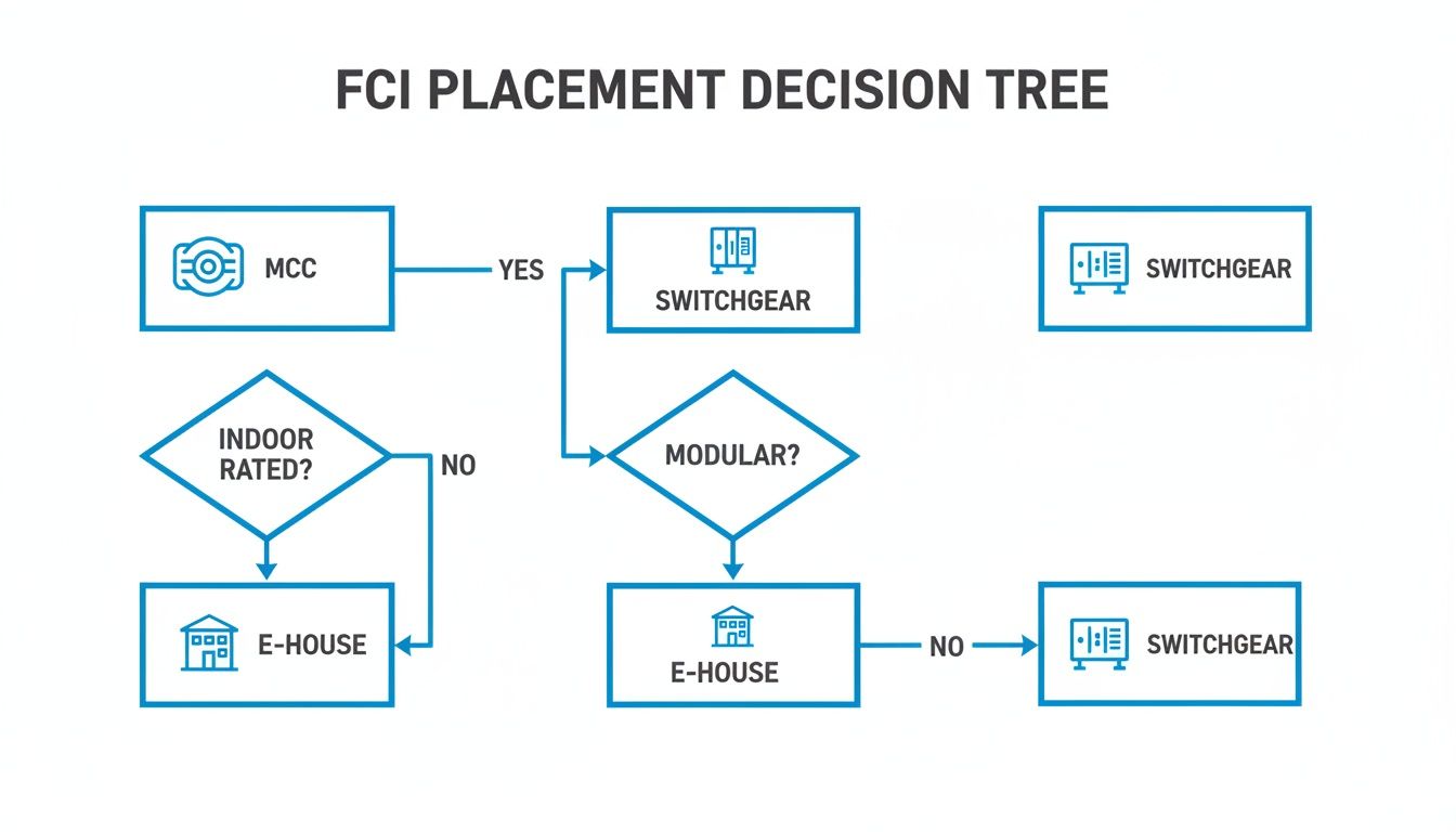
As you can see, factors like whether it's an indoor setup or if you need modularity help point you toward the right home for the FCI, whether that's an MCC, switchgear, or E-House.
Setting the Right Trip Threshold
Once you've got the basic ratings nailed down, the most critical setting is the trip threshold. This is the magic number that tells the FCI, "Okay, this is a fault." Getting it right is everything.
The trip threshold of a fault current indicator must be set high enough to ignore temporary inrush currents—like those from a large motor starting—but low enough to reliably detect the smallest genuine fault current your system can produce.
Thankfully, many modern fault current indicators are smart enough to handle this themselves with self-adjusting trip settings. For instance, a device might watch the load current for a while and then automatically set its trip point at something like four times the measured load. This dynamic approach is brilliant because it prevents false alarms from normal operations while staying sharp enough to catch real faults.
FCI Technology Comparison for Industrial Use
Not all FCI sensors are created equal. The technology inside—whether it's a simple magnetic field sensor or a more sophisticated Rogowski coil—directly impacts its performance and where it fits best. Choosing between them depends on what you're trying to achieve, from basic fault flagging to more precise analysis.
The table below breaks down the two most common types to help you decide.
| Feature | Magnetic Field Sensor FCI | Rogowski Coil FCI | Best Application Scenario |
|---|---|---|---|
| Operating Principle | Senses the magnetic field produced by fault current. | A flexible coil measures the rate of change of current (di/dt). | Magnetic sensors are great for straightforward overcurrent detection. Rogowski coils are for more nuanced applications. |
| Accuracy & Linearity | Generally lower accuracy; can become saturated by high currents. | Highly accurate and linear across a very wide current range. | For simple "go/no-go" fault flagging, magnetic sensors are fine. For systems needing precise data, go with Rogowski. |
| Installation | Typically a simple clamp-on or split-core design. Quick to install. | Flexible "rope-style" coil is easy to wrap around large or awkward busbars. | Both are relatively easy, but Rogowski coils really shine in tight spots or on large, non-standard conductors. |
| Cost | More cost-effective for basic applications. | Generally more expensive due to higher precision and electronics. | If you just need to know where a fault happened, a magnetic FCI is a budget-friendly workhorse. |
| Inrush Handling | Can be prone to nuisance trips from motor inrush if not set properly. | Better at distinguishing between transient inrush and true fault current. | In motor-heavy environments like MCCs, a Rogowski coil's superior inrush handling is a huge advantage. |
Ultimately, for a basic feeder where you just need to know if a fault occurred, a magnetic field FCI is often all you need. But in a complex system with variable loads or where you need to avoid any chance of a false trip, the precision of a Rogowski coil is well worth the investment.
Short Circuit vs. Earth Fault Detection
Faults come in different flavors. A phase-to-phase short circuit is a sledgehammer—a massive, obvious surge of current. But an earth fault, where current leaks to the ground, can be a whisper. It's often far more subtle and trickier to track down.
You need to decide which type of fault you're hunting for:
- Short Circuit Indicators: These are the bread and butter. They're designed to catch those high-magnitude phase-to-phase or phase-to-ground faults.
- Earth Fault Indicators: These are the specialists. They're more sensitive and often use a summation current sensor that wraps around all three phase conductors. By measuring any imbalance or "leaked" current, they can detect very low-level ground faults that a standard FCI would completely miss.
For critical systems where a sneaky ground fault could cause serious damage or downtime, investing in an indicator with dedicated earth fault detection is a no-brainer.
Communication and Environmental Factors
Last but not least, think about how the FCI is going to talk to you and what kind of environment it's going to live in.
-
Indication Method: Is a simple flashing LED on the unit enough for your local crew? Or do you need that fault signal sent straight to a central SCADA or PLC system? Remote communication gives your control room immediate alerts, kicking off a much faster, system-wide response.
-
Environmental Ratings: Industrial plants are not friendly places. Look for an FCI with a high IP rating, like IP68, to seal it against dust and water. You also need to check its operating temperature range to make sure it can handle its home, whether that's a climate-controlled E-House or a sun-baked outdoor switchyard.
Getting Installation and Integration Right
You can specify the perfect fault current indicator, but it’s all for nothing if the installation is botched. Proper installation isn’t just the last step on a checklist; it's the very foundation of the device's reliability. Getting these details right from the start means your FCI will be ready to perform exactly as designed the moment a fault occurs.
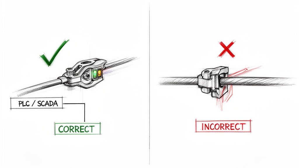
It all starts with getting the sensor physically positioned and oriented correctly on the conductors. This is what guarantees you'll get accurate readings. Get it wrong, and the sensor might miss a fault entirely or—just as bad—trigger a false alarm. Think of it as the mechanical bedrock for the entire system's electrical performance.
Sensor Placement and Orientation
Let’s be clear: properly mounting the sensor is non-negotiable for accurate fault detection. The FCI has to be installed on the correct phase conductors and oriented precisely according to the manufacturer’s specs.
Simple mistakes here can snowball into major problems. For example, mounting a sensor backward or on the wrong side of a connection can completely scramble how it interprets current flow and magnetic fields. That leads to flaky, unreliable performance right when you need it the most.
For earth fault detection, the rules are even more specific when using a summation current sensor. This sensor absolutely must encircle all three phase conductors of the circuit. Its entire job is to measure the vector sum of the currents. If anything is out of balance, it means current is leaking to the ground—the classic signature of an earth fault.
Wiring for Local and Remote Indication
With the sensor locked in place, the next job is to wire up the indication and communication outputs. These connections are how the FCI "talks," telling your team when and where a problem has cropped up.
The wiring typically follows two key pathways:
- Local LED Indicators: These are the high-visibility LEDs for personnel on the floor. Wiring them should be straightforward, running from the FCI’s output terminals to the light. The key is ensuring a secure, weather-resistant connection that will last.
- Remote Communication Outputs: To tie into a central control system, you'll connect the FCI’s relay or digital output to your PLC or SCADA system. This demands close attention to the wiring diagrams to make sure the signal transmission is clean and compatible.
An improperly terminated communication wire is a silent failure. Your FCI might detect a fault perfectly, but if the signal never reaches the control room, the primary benefit of rapid, system-wide response is completely lost.
Dodging Common Installation Pitfalls
There are a few common, but totally avoidable, mistakes that can torpedo a fault current indicator installation. Knowing what they are is the best way to defend against them and ensure your system is solid from day one.
A classic error is improper grounding of the FCI unit or its wiring. This can introduce electrical noise that messes with the sensitive electronics inside, leading to erratic behavior or nuisance trips.
Another frequent hang-up is misconfiguring the communication protocols when linking the FCI to a PLC or SCADA system. Mismatched baud rates or incorrect addressing means the systems can't talk to each other, effectively cutting your smart device off from the control network. It pays to take the time to double-check these settings during commissioning—it's critical for a successful integration.
Getting It Right: Testing, Commissioning, and Troubleshooting
A fault current indicator is useless if it doesn't work when you need it most. That’s why proper testing, a solid commissioning process, and a clear troubleshooting plan aren’t just "nice-to-haves"—they're absolutely essential. This is how you turn a newly mounted piece of hardware into a reliable guardian for your electrical system.
The journey from a fresh install to a trusted asset starts with commissioning. This is the final quality check before you flip the switch, a series of real-world tests to confirm the FCI works exactly as it should.
Commissioning Your Fault Current Indicators
Before you can trust an FCI, you have to prove it. The gold standard for this is primary injection testing.
This isn't a simulation; you're actually injecting a controlled, fault-level current right through the conductor the FCI is monitoring. It's the most realistic way to see if the indicator trips at its designated threshold. This test validates everything—the sensor, the internal logic, and the flag or light that signals a fault.
And don't forget the communication links. If your FCI is tied into a SCADA or PLC system, you need to confirm that a trip signal actually makes it back to the control room. A quick check here ensures your remote monitoring is ready to go from day one.
Sticking to a Routine Maintenance Schedule
Once they're up and running, FCIs are pretty low-maintenance. But "low" doesn't mean "no." A simple, proactive maintenance schedule keeps them ready for action and prevents nasty surprises down the road.
A good plan is straightforward:
- Visual Inspections: Give the units a regular once-over. Look for any physical damage, dirt buildup, or signs of moisture that could compromise the housing. Make sure the LEDs or flags are clean and easy to see.
- Battery Health Checks: For battery-powered units, just follow the manufacturer's guidelines. Most modern FCIs have a low-battery LED, so this is often just a quick look to make sure the light isn't on.
- Communication Verification: Every so often, trigger a manual test (if the unit has that feature) to double-check that the signal path to your central control system is still solid.
This kind of proactive care is a big deal, especially in tough industrial environments. In fact, the market for these devices is expected to grow significantly by 2035, largely because facilities need better diagnostics on cables that are constantly exposed to moisture, heat, and physical stress. Consistent maintenance is what guarantees they’ll be reliable when things get rough. You can find more market insights and trends over at futuremarketinsights.com.
Common Troubleshooting Scenarios
Even with a perfect install, things can go sideways. Having a go-to troubleshooting guide helps your maintenance crew sort out problems fast.
Problem: The indicator tripped, but there was no fault.
This is a classic "nuisance trip." The most common culprit is a trip threshold set too low, making the FCI over-sensitive to normal inrush currents when a big motor starts up. The fix is to review the settings and adjust the trip point to be safely above the maximum inrush current but still well below the minimum fault current.
Problem: A known fault occurred, but the FCI didn't trip.
This one’s more serious. It could be anything from a dead battery or a failed sensor to a trip setting that’s just too high to catch the fault. Start with the simplest check: the power source. If that's good, then it's time to verify the settings are actually matched to your circuit's specific fault characteristics.
Got Questions About FCIs? We've Got Answers.
Even after you've got the basics down, a few practical questions always seem to pop up when it's time to actually specify and install fault current indicators. I get these all the time from engineers and technicians in the field, so let's walk through the most common ones to clear up any lingering confusion.
What's The Real Difference Between An FCI And A Circuit Breaker?
Think of them as two specialists on the same emergency response team. The circuit breaker is the firefighter—it rushes in and actively stops the danger by interrupting the fault current. Its entire job is to protect the circuit from catastrophic damage.
The fault current indicator, on the other hand, is the forensic expert who arrives after the scene is secured. It doesn't stop the fault. It simply "witnesses" it and leaves a clear visual marker, pointing a big red arrow right at where the trouble happened. This lets your maintenance crew head straight to the source instead of wasting hours on frustrating trial-and-error testing.
Will A Motor Starting Up Cause A False Trip?
That's a great question, and the answer is no—at least not with any modern FCI worth its salt. While a very simple, old-school FCI with a fixed trip setting could be fooled by motor inrush, today's advanced units are much smarter.
Many of the best FCIs on the market have a self-adjusting trip threshold. The device actively monitors the normal load current and automatically sets its trip point well above it—often four times the sustained load. This clever logic allows it to completely ignore temporary, high-current events like a motor kicking on, yet it stays sensitive enough to instantly catch a genuine short circuit or ground fault.
How Long Can I Expect The Batteries To Last?
This is a key concern, especially for units installed in hard-to-reach places. The good news is that longevity is a primary design goal for battery-powered FCIs. Most are equipped with high-density lithium batteries engineered for an incredibly long service life, typically lasting 15 to 20 years in normal operating conditions.
Plus, you won't be caught by surprise. These devices almost always include a low-battery alert, like a dedicated yellow LED, which gives you plenty of notice to schedule a replacement long before the unit stops monitoring.
Do I Need To Calibrate These Things Regularly?
Nope. Generally, fault current indicators are designed to be "fit-and-forget" devices. The sensor technology—whether it's a simple magnetic switch or a more advanced Rogowski coil—is inherently stable and doesn't drift over time.
Your routine maintenance should really just focus on the simple stuff: quick visual inspections, checking the battery status on powered units, and making sure any communication links are solid. The core fault-sensing mechanism itself doesn't need periodic recalibration, which is great for minimizing the long-term cost of ownership and ensuring they’re always ready to do their job.
At E & I Sales, we specialize in integrating robust solutions like fault current indicators into custom UL control panels, switchgear, and modular electrical buildings to enhance system reliability and safety. Explore our engineering services and products at https://eandisales.com.