
When we talk about electrical substation design, we're really talking about the blueprint for the heart of our power grid. It's the whole engineering process—from initial concept to final commissioning—that brings a substation to life. At its most basic level, a substation is all about transforming voltage. It either steps it up to send power efficiently over long distances or steps it down so it can be safely used in our homes and businesses.
Why Substations Are the Heart of the Power Grid
Think of a substation as a critical traffic interchange for electricity. You wouldn't just connect a massive interstate directly to a quiet neighborhood street, right? You need on-ramps, off-ramps, and interchanges to manage the flow. A substation does exactly that for electrical power, directing it where it needs to go safely and reliably. Without these crucial nodes, our grid would be a chaotic, single-voltage mess, completely unable to power distant cities or local factories.
Every single design decision boils down to getting three things right:
- Safety: This is non-negotiable. Protecting people from the dangers of high-voltage equipment is always the top priority.
- Reliability: The goal is an uninterrupted flow of power. This means building in redundancy and robust protection systems to handle faults without causing widespread blackouts.
- Cost-Effectiveness: It's a balancing act. The design needs to deliver on performance and safety without breaking the bank, both in initial construction and for long-term operation.
Exploring Different Types of Substations
No two substations are exactly alike. Their design is dictated entirely by the job they need to do within the larger power grid. They can be massive, complex facilities spread across acres of land or small, compact units tucked onto a concrete pad behind a shopping center. The first step to understanding their design is knowing their purpose.
For example, a transmission substation is like a major international airport. It handles huge amounts of power at extremely high voltages, often acting as the connection point between multiple power plants and the main transmission lines. A distribution substation, on the other hand, is more like a local bus station. It takes that high-voltage power from the transmission lines and steps it down for final delivery to neighborhoods and industrial parks.
A huge goal in modern electrical substation design is to maximize efficiency while shrinking the physical footprint, especially in crowded urban areas. This challenge has been a major driver of technological innovation over the years.
To give you a clearer picture, here's a quick breakdown of common substation types and what they do.
Substation Types and Their Primary Functions
This table provides a simple overview of the different kinds of substations you'll find, their typical voltage ranges, and their specific roles in getting power from the generator to your wall outlet.
| Substation Type | Typical Voltage Level | Primary Function | Common Location |
|---|---|---|---|
| Generator Step-Up | 13.8kV to 765kV | Increases voltage from power plants for long-distance transmission. | Adjacent to power generation facilities (hydro, nuclear, gas). |
| Transmission | 230kV to 765kV | Interconnects high-voltage lines, forming the backbone of the grid. | Strategic points along major power corridors, often in rural areas. |
| Sub-transmission | 69kV to 138kV | A middle tier, stepping down voltage for regional distribution. | On the outskirts of metropolitan areas or large industrial zones. |
| Distribution | 4kV to 34.5kV | Steps down voltage for delivery to end-users. | Within local communities, neighborhoods, and commercial areas. |
| Switching Station | All levels | A "traffic cop" that redirects power flow without changing voltage. | Key interconnection points within the grid to improve reliability. |
Each type serves a unique purpose, and the design complexity and equipment choice vary dramatically from one to the next.
This constant push for smaller, safer substations led to a huge breakthrough in the mid-20th century: the Gas-Insulated Substation (GIS). By using sulfur hexafluoride (SF6) gas as an insulator instead of open air, engineers could drastically shrink the size of switchgear for voltages from 72.5 kV all the way up to 800 kV. This was a game-changer, making it possible to build powerful substations in tight city spaces where it was previously impossible. You can learn more about the history of gas-insulated substations and how they shaped the modern grid.
With this foundational understanding of what a substation does and why we have different types, we're ready to dive into the technical details of site layouts, one-line diagrams, and equipment selection.
Developing the Substation Design Blueprint
Every solid substation design starts long before the first shovel hits the dirt. It begins with a blueprint—a detailed plan that turns raw power requirements into a tangible, workable design. This whole process is what lays the foundation for a safe, reliable, and efficient facility. And the very first big decision you have to make is site selection.
Choosing the right spot is a balancing act. You've got to think about technical needs and real-world constraints. How close are we to the existing transmission lines? The closer, the better, as it cuts down on connection costs. But you also need to make sure construction crews and, later, maintenance teams can actually get to the site. Then you layer on environmental studies, land costs, and local zoning laws. Get this wrong, and you could be dealing with unnecessary costs and operational headaches for years to come.
From Site Selection to Physical Layout
Once you’ve got the land, the focus shifts to the physical layout. This is where you start arranging all the major equipment. Think of it like setting up a workshop; you need enough space around each piece of machinery for people to work safely and for routine maintenance to happen without a fuss.
In a substation, that "space" is critical. We're talking about maintaining proper electrical clearances between high-voltage gear and anything grounded to prevent a dangerous arc flash. The layout also has a huge impact on how easily technicians can access things like circuit breakers and transformers for inspections. A smart layout always leaves a little extra room, because you can bet that the demand for power is only going to grow.
Decoding the One-Line Diagram
If there’s one document that’s the heart and soul of any substation design, it's the one-line diagram. This is the master map. It shows how every single piece of equipment is electrically tied together, from the high-voltage lines coming in to the feeder circuits going out. Instead of a messy schematic showing all three electrical phases, it simplifies everything into a single, clean line. It makes the entire system much easier to understand at a glance.
This diagram is the common language for everyone involved—engineers, operators, and the maintenance crew. To get a better sense of where the substation fits into the bigger picture, take a look at this.
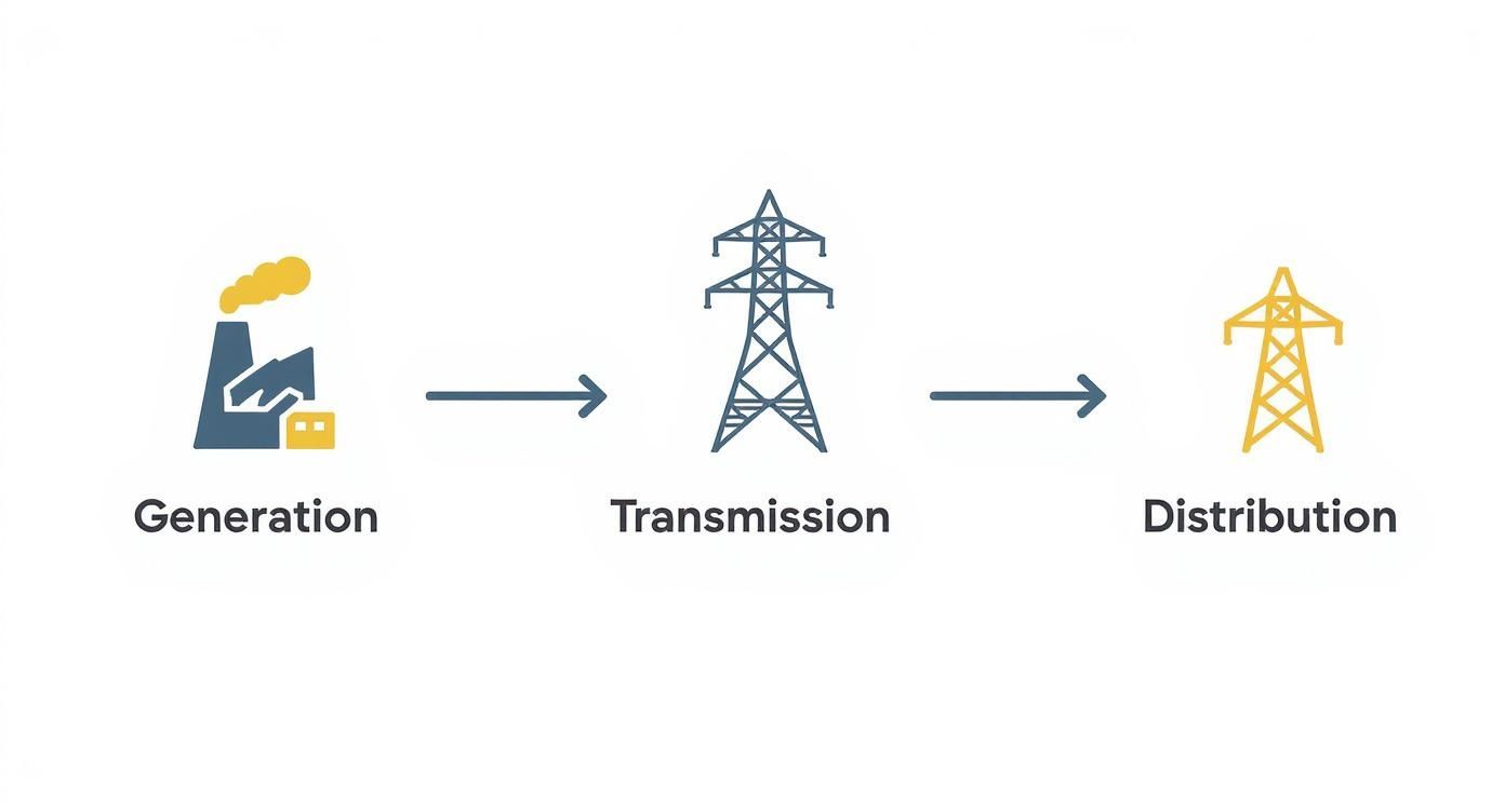
This shows how substations are the crucial middleman, stepping down the high-voltage power from transmission lines to a lower voltage that can be distributed out to homes and businesses. The one-line diagram zooms in on what’s happening inside that box.
Let's walk through a simplified path on a diagram for, say, an industrial plant:
- Incoming Line: Power arrives from the utility on a high-voltage line.
- Disconnect Switch: The first stop is usually a big manual switch. Its job is to completely isolate the substation from the grid so crews can work safely.
- Circuit Breaker: Right after the switch is the main circuit breaker. This is the primary automatic safety device that will trip and cut power if there's a fault.
- Power Transformer: From there, the electricity flows into a step-down transformer. This is what drops the voltage to a level that the plant's motors and machinery can actually use.
- Main Bus: The transformer then feeds a central conductor, what we call a busbar. Think of it as a power strip for the whole facility.
- Feeder Breakers: Connected to this bus are several smaller breakers, each protecting an individual "feeder" circuit that runs to a specific area or piece of equipment in the plant.
By laying out the sequence and relationship of every major component, the one-line diagram becomes the absolute single source of truth for the entire electrical system. It's an indispensable tool for troubleshooting, planning maintenance, and operating the substation safely.
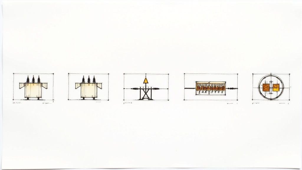
Selecting Critical Substation Equipment
An electrical substation design is only as good as the hardware that brings it to life. Once the one-line diagrams and layouts are nailed down, the real work begins: picking the actual equipment that will manage the flow of power.
Think of it like building a race car. You've got the chassis design, but now you need to choose the engine, the transmission, and the brakes. Every single component has to be tough, reliable, and perfectly matched to what you're trying to achieve. Get this part wrong, and the whole project is at risk.
This isn't just a shopping trip. It's a deep dive into technical specs, a careful balancing act between cost, performance, and what will keep the lights on for the next 30 years.
The Heart of the Substation: Power Transformers
If a substation has a heart, it's the power transformer. It's almost always the single most expensive piece of gear on site, and its job is non-negotiable: changing voltage levels. Picking the right one is absolutely fundamental to the whole design.
You can't just guess here. The selection comes down to hard numbers:
- Power Rating (MVA): This is the transformer's raw muscle. It tells you how much power it can handle continuously. You figure this out by adding up all the loads it will serve, then tacking on a healthy margin for future expansion.
- Voltage Levels: It has to perfectly match the grid's incoming voltage and the plant's distribution voltage. For instance, a common setup in an industrial site is stepping down from a 34.5kV utility feed to a more usable 4.16kV for running large motors.
- Cooling Method: Transformers throw off a ton of heat. How they get rid of it—whether it’s through natural air circulation (ONAN) or with the help of fans (ONAF)—directly affects how hard you can run it and how long it will last.
Switchgear: The Brains and Brawn
While the transformer is the heart, the switchgear is the nervous system and the muscles all rolled into one. It’s the collection of circuit breakers, switches, and protective relays that acts as the traffic cop for the entire system.
This is the equipment that safely connects and disconnects circuits, whether for routine maintenance or in the split second a fault occurs. To get a feel for how these critical protective devices work, you can see our breakdown of the ABB circuit breaker and its role in the system.
One of the biggest forks in the road for any design is the type of switchgear technology you choose.
The choice between Air-Insulated Switchgear (AIS) and Gas-Insulated Switchgear (GIS) represents a fundamental trade-off between physical space, environmental conditions, and project budget.
This choice really tells a story about the evolution of substation design. Back in the day, everything was big, open, and air-insulated. But the 1960s brought a revolution with GIS technology, which shrank the footprint of a substation by nearly 90%. This was a game-changer for cities where land is gold, allowing high-voltage substations to be built indoors for the first time.
- Air-Insulated Switchgear (AIS): This is the old-school, tried-and-true method. It uses the air around the conductors as the primary insulator. It’s reliable and relatively cheap, but it needs a lot of real estate to maintain safe clearances.
- Gas-Insulated Switchgear (GIS): This is the high-tech, compact solution. All the live parts are sealed inside a metal enclosure filled with an insulating gas (like SF6). GIS is incredibly small, secure, and shrugs off nasty environmental conditions like salt spray or dust. The trade-off? A much higher upfront cost.
No matter which you choose, you have to think about keeping it running for decades. Modern utility maintenance and power line inspection techniques have come a long way in making this easier and safer.
Busbar Configurations: The Electrical Roadway
Inside the switchgear, all the circuits—both incoming and outgoing—connect to a common conductor called a busbar. The easiest way to think of it is as the main electrical highway running through the substation.
How you arrange these "highways" has a massive impact on both reliability and your ability to perform maintenance without shutting everything down. It's a classic engineering trade-off: simplicity and low cost versus flexibility and high reliability.
Comparison of Common Busbar Configurations
This table breaks down the most common arrangements, showing how each one stacks up in the real world.
| Busbar Scheme | Relative Cost | Reliability | Operational Flexibility | Best Use Case |
|---|---|---|---|---|
| Single Bus | Low | Low | Low | Small industrial plants or distribution substations where brief outages are acceptable. |
| Double Bus | High | High | High | Critical transmission stations or large industrial facilities where reliability is paramount. |
| Ring Bus | Medium | High | Good | Distribution and sub-transmission substations needing a good balance of cost and reliability. |
As you can see, there's no single "best" answer. A small manufacturing plant might be perfectly happy with a simple and cheap single bus. But for a hospital, a data center, or any critical facility, the extra investment for a rock-solid ring or double bus configuration is a no-brainer.
Essential Auxiliary Systems
Finally, you can't forget the support crew. The most critical backup player in any substation is the DC battery bank.
This isn't just for emergency lights. This system provides the clean, uninterrupted power needed to run the protection relays and control circuits. If the main power goes out completely, it’s the battery bank that ensures the circuit breakers can still operate, allowing the substation’s “brain” to stay online and safely manage the restoration of power.
When you boil it all down, a substation has two jobs that tower above everything else: keeping people safe and protecting the millions of dollars of equipment that make the grid work. These aren't just bullet points on a spec sheet; they're the core principles that drive every single design decision.
This responsibility plays out on two levels that are separate but deeply connected. First, you have the physical safety of anyone setting foot on the site, which is all about a rock-solid grounding system. Second, you have the operational safety of the entire system, which is handled by a sophisticated network of protection relays—the substation's digital nervous system.
The Foundation of Safety: Grounding Systems
A good grounding system is the substation's silent, unseen guardian. Its primary purpose is to give fault currents an easy, low-resistance path straight into the earth. Without it, something like a lightning strike or a short circuit could turn every metal object on site—from the perimeter fence to the equipment housings—into a lethal hazard.
The system is basically a grid of heavy copper conductors buried just below the surface, creating what we call an equipotential plane. In simple terms, this grid works to keep the voltage across the ground surface as even as possible during a fault. This prevents deadly voltage differences from developing between a worker's feet (step potential) or between their hand and a piece of energized equipment (touch potential).
A well-designed ground grid ensures that even in a worst-case fault scenario, these voltages stay below survivable limits. Our guide on understanding ground fault protection digs deeper into how these systems are the first line of defense against electric shock.
Designing one involves some serious number-crunching. Engineers have to factor in soil resistivity (which can vary wildly), maximum available fault current, and the physical footprint of the substation to get the conductor size and grid spacing just right.
The Vigilant Guards: Protection and Control Relays
If the grounding system is the passive, physical shield, then the relaying system is the active, intelligent defense. Think of protection relays as a team of hyper-vigilant digital guards, each one assigned to watch over a specific piece of equipment. Every relay is programmed to know exactly what normal operating conditions look like for its zone—be it a transformer, a bus, or a transmission line.
The second they spot an anomaly—like the massive inrush of current from a fault—they don't hesitate. They don't fix the problem directly, but they do the next best thing: they send an instantaneous "trip" signal to the right circuit breaker, which physically opens the circuit to isolate the problem area.
This idea of selective coordination is the bedrock of modern substation protection. The whole point is to disconnect the absolute smallest part of the system necessary to clear a fault. It’s what prevents a single downed line from taking out an entire city.
This coordination works like a chain of command. The relay closest to the fault is supposed to act first. If for some reason it fails, the next relay upstream is programmed to provide backup protection after a brief, intentional delay. It's a built-in failsafe to make sure the fault always gets cleared.
Zones of Protection and Relay Coordination
To make this kind of surgical precision possible, engineers divide the entire substation into distinct zones of protection. Each zone is defined by the current transformers (CTs) that act as the relays' eyes and ears, feeding them real-time data.
- Transformer Zone: Here, a differential relay meticulously compares the current going into the transformer with the current coming out. If they don't add up perfectly, it knows there’s an internal fault and trips the breaker.
- Bus Zone: This scheme monitors every amp flowing into and out of the main bus. Any imbalance is a dead giveaway that there's a fault on the bus itself—one of the most severe types of faults.
- Line Zone: Distance relays protect the long transmission lines. By calculating the impedance from the substation to the fault, they can pinpoint its location with incredible accuracy and decide whether to trip.
The evolution of these "guards" has been remarkable. Early substations relied on simple fuses and clunky electromechanical relays. But the invention of the first microprocessor-based relay in 1979 was a complete game-changer, packing dozens of protection functions into one smart, programmable box. These modern numerical relays are now the undisputed standard, giving us the speed, precision, and communication capabilities that today's grid depends on.
Implementing Modern Automation with SCADA
A modern substation isn't just a passive collection of steel and wire anymore; it's an intelligent, interconnected hub. That intelligence comes from a system known as SCADA (Supervisory Control and Data Acquisition), which acts as the brain and nervous system for the entire facility, enabling remote management and smart automation.
Think of an operator sitting in a control room, potentially miles away from the substation itself. SCADA is what gives them a live, real-time window into everything that’s happening—from the temperature of a main transformer to the exact power flowing through every single circuit. Even better, it lets them take action. They can remotely trip a breaker to isolate a fault or reroute power to head off an overload, all with a few clicks.
Core Components of a SCADA System
SCADA isn't one single box you buy. It’s an entire ecosystem of components, all working in concert. Grasping how these pieces fit together is the key to understanding how a modern substation really ticks.
It all starts at the ground level with Intelligent Electronic Devices (IEDs). These are your smart relays, meters, and sensors—the eyes and ears of the system. They’re directly connected to the equipment, constantly measuring vitals like current, voltage, and temperature.
This raw data gets gathered up by a Remote Terminal Unit (RTU) or a gateway inside the substation. The RTU is like a local data manager; it bundles all the information from the IEDs and sends it back to the central control center over a communication network, whether that’s fiber optic cable or a wireless link.
The real magic of SCADA is how it centralizes information and control. It turns a chaotic flood of isolated data points into a clear, actionable picture of the entire grid, paving the way for faster, smarter decisions when they matter most.
Finally, back at the control center, all this data is displayed on a Human-Machine Interface (HMI). These are the user-friendly screens where operators see alarms, track performance trends, and send commands back out to the field, closing the control loop. While the concepts can seem similar, it helps to understand the nuances between different platforms; our article exploring SCADA vs DCS digs deeper into these control systems.
The Role of Communication Protocols
For all these different devices to talk to each other, they need to speak the same language. That’s where communication protocols come in. In the old days, this meant running complex, custom wiring for everything. Modern standards have completely changed the game.
The undisputed heavyweight champion in substation design today is IEC 61850. It’s much more than just a protocol; it's a comprehensive framework that defines how everything communicates.
Here’s what makes it so important:
- Interoperability: It allows IEDs from completely different manufacturers to talk to each other flawlessly. This is huge—it gives you the freedom to pick the absolute best device for a specific job without getting locked into a single vendor.
- High-Speed Communication: IEC 61850 enables devices to send peer-to-peer messages directly to each other over the local network. This allows for lightning-fast protection schemes where IEDs can coordinate to isolate a fault in a matter of milliseconds.
- Drastically Reduced Wiring: Instead of running miles of copper control cables, communication flies over a few thin fiber optic strands. This massively simplifies construction, slashes costs, and gets rid of countless potential points of failure.
By integrating SCADA and adopting standards like IEC 61850, a substation evolves beyond just stepping voltage up or down. It becomes a dynamic, responsive asset that strengthens grid stability, accelerates fault response, and ultimately delivers more reliable power to everyone.
Navigating the Substation Project Lifecycle
Taking a substation from a blueprint to a humming, energized facility isn't a single event—it's a journey. This is a highly structured, multi-phase process designed to make sure every single detail is nailed down, from the big-picture concept to the final flick of the switch. It’s where engineering theory gets its hands dirty and meets real-world construction.
You can think of the whole project lifecycle as a roadmap. It guides the team from a simple idea scribbled on a napkin to a fully operational asset, ensuring no critical steps are missed along the way.
From Concept to Detailed Engineering
Everything starts with the conceptual design and a good, hard look at feasibility. This is the 30,000-foot view where we define the project's core mission. What's this substation for? What kind of capacity does it need? And where in the world will it live? This initial phase locks in the preliminary budget and timeline.
Once the concept gets the green light, we dive deep into detailed engineering. This is where the real magic happens. One-line diagrams are finalized, physical layouts are drafted, and every last nut, bolt, and component gets specified. What comes out of this stage is the complete set of construction drawings and technical specs—the bible for the entire build.
The success of any electrical substation design is built on a disciplined project lifecycle. Sticking to industry standards from bodies like IEEE and IEC isn't just a suggestion; it's absolutely essential for delivering a safe, reliable, and long-lasting final product.
Procurement and Construction Management
With the engineering plans in hand, the procurement phase kicks into high gear. This is all about ordering the big-ticket items: the power transformer, the switchgear, and the control panels. You have to be smart about it, especially with long-lead items. A custom-built transformer can take months to manufacture, so getting that order in early is key to keeping the whole project on schedule.
At the same time, the hard hats go on and the construction phase begins. This usually starts with civil works—grading the site and pouring massive concrete foundations. Then comes the steel, as support structures rise from the ground. As the big equipment arrives, it's carefully installed, and crews get to work pulling and terminating what can feel like miles of power and control cables.
The Final Step: Commissioning and Energization
The final sprint to the finish line is the commissioning phase. This is an absolutely exhaustive series of tests on every single piece of equipment and every system. Technicians run through their checklists, verifying everything.
- Do the protection relays trip when they're supposed to? Check.
- Do the circuit breakers open and close correctly? Check.
- Are all the communication links to the SCADA system up and running? Check.
Only after every single test is passed with flying colors can the substation be safely energized and officially handed over for service. It’s this rigorous, step-by-step process that turns a complex electrical design into a dependable, operational reality.
Of course. Here is the rewritten section, designed to sound completely human-written and natural, following the style and tone of the provided examples.
Your Top Substation Design Questions, Answered
Even with the best guides, big projects like substation design always bring up specific questions. It’s a complex field, and it’s natural to want to clarify a few things before breaking ground.
This section is your quick-reference guide. We’ll tackle the most common questions we hear from engineers and project managers, cutting through the jargon to give you straight answers.
AIS vs. GIS: Which One Do I Actually Need?
One of the first big decisions is whether to go with an Air-Insulated Substation (AIS) or a Gas-Insulated Substation (GIS). The right choice really comes down to a classic trade-off: space versus cost.
Think of an AIS as the traditional, open-air approach. It uses the air around it to insulate high-voltage components. It’s a proven, reliable, and cost-effective method, but it needs a lot of room to maintain safe electrical clearances. If you’ve got plenty of land—say, in a rural or suburban area—an AIS is often the most practical choice.
A GIS, on the other hand, is the compact, modern solution. It seals every live component inside a metal-clad unit filled with insulating gas (SF6). This design is incredibly efficient with space, shrinking the substation’s footprint by up to 90% compared to an AIS. For tight urban spaces, offshore platforms, or any industrial site where every square foot counts, GIS is the clear winner.
What Are the Absolute Top Priorities for Safety?
When it comes to high-voltage environments, safety isn't just a priority; it's everything. You’re not just protecting expensive equipment; you’re protecting lives. A few non-negotiables should be at the top of every design checklist.
- A Rock-Solid Grounding System: This is your first line of defense. A well-designed grounding grid is critical for managing fault currents and preventing deadly step and touch potentials for anyone working on-site.
- Secure Fencing and Controlled Access: It sounds basic, but physical security is vital. You have to keep unauthorized people out of hazardous areas, period.
- Proper Clearances, No Exceptions: Keeping enough space between live equipment and grounded structures is fundamental. It’s the key to preventing catastrophic arc flashes.
- Smart Insulation Coordination: This is how you protect your multi-million dollar transformers from getting fried by a lightning strike or a switching surge.
At the end of the day, every design decision has to be seen through a safety lens. Sticking to established codes like the National Electrical Safety Code (NESC) isn't optional—it's what ensures your facility is both reliable and safe for the people who run it.
How Is Automation Changing the Game for Substations?
Automation has completely transformed substations from passive electrical junctions into the intelligent, active nerve centers of the modern grid. Thanks to SCADA systems and advanced protocols like IEC 61850, we can do things today that were just a dream a couple of decades ago.
This technology gives operators real-time visibility and remote control, allowing them to spot and react to problems in seconds, not hours. Automation also powers predictive maintenance; by analyzing equipment data, you can fix issues before they cause a failure. It makes the entire grid more resilient, automatically detecting and isolating faults to get the power back on faster than ever after an outage.
For over 50 years, E & I Sales has been a trusted partner in delivering reliable motor control, automation, and power distribution solutions. From initial specification to final commissioning, our team provides the expertise and high-quality equipment needed to bring your most complex industrial projects to life. Connect with us to see how we can support your next upgrade, expansion, or greenfield installation at https://eandisales.com.