
At their core, the difference between a contactor and a relay comes down to muscle versus finesse. A contactor is the heavy-duty switch you need for brawny, high-current loads like electric motors and industrial lighting. A relay, on the other hand, is a precision switch built for delicate, low-current control signals and logic circuits. Your choice hinges on a simple question: are you switching serious power or just controlling information?
Understanding The Key Differences
While both devices use the same electromagnetic principle—a coil closing a set of contacts—they are fundamentally engineered for completely different jobs. You can think of a contactor as a super-sized, beefed-up relay, built with rugged features to safely handle the immense electrical stresses that come with industrial equipment. In contrast, a relay’s design is all about speed, precision, and low power draw for signal-level switching.
The distinction is absolutely critical when you're dealing with inductive loads like motors. When a motor starts, it draws a massive inrush of current, often 6 to 8 times its normal running load. A contactor is specifically designed to take that punch without its contacts welding themselves shut.
More importantly, it has built-in safety features like arc suppression chutes. These are essential for extinguishing the powerful electrical arc that forms when you try to break a high-current circuit—a feature you simply won't find on a standard relay.
Trying to use a relay where a contactor is needed is a recipe for catastrophic failure. It's a major safety risk and a surefire way to destroy your equipment. On the flip side, using a bulky contactor for a tiny control signal is just overkill—inefficient and unnecessarily expensive. Getting this right is the first step in building a control system that is safe, reliable, and cost-effective.
Quick Comparison Contactor vs Relay At a Glance
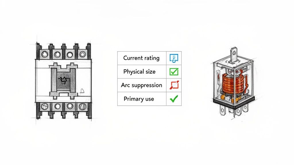
For a quick side-by-side view, this table breaks down the main differences between contactors and relays across the most important characteristics. It's a handy reference for seeing where each device shines.
| Characteristic | Contactor | Relay |
|---|---|---|
| Current Rating | High (typically > 10A, often hundreds of Amps) | Low (typically < 10A) |
| Primary Application | Switching high-power loads (motors, heaters, lighting) | Switching low-power control signals (PLC outputs, logic) |
| Physical Size | Large and robust | Small and compact |
| Arc Suppression | Yes, built-in arc chutes are standard | No, not designed for high-current arcing |
| Safety Features | Designed for high fault currents and safety | Designed for signal isolation and control logic |
| Contact Type | Normally Open (NO) is standard for power | Both Normally Open (NO) and Normally Closed (NC) are common |
| Cost | Higher | Lower |
Ultimately, this table reinforces the core idea: contactors are built for power, and relays are built for control. Knowing when to use which is fundamental to sound electrical design.
Exploring The Design and Operating Principles
To really get the difference between a contactor and a relay, you have to look past the fact they both use an electromagnet and dive into how they're built. At a high level, sure, they both use a small electrical signal to switch a bigger one. But crack them open, and you see two totally different philosophies at work.
A contactor is a brute—a fortress built to handle serious power. A relay, on the other hand, is a precision instrument, designed for logic and control. The internal guts of each device tell the whole story.
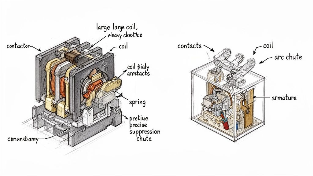
Contactor Construction: Built for Power and Safety
Every piece inside a contactor is beefed up for one reason: survival. The coil is bigger and needs more juice to create a magnetic field strong enough to slam those heavy contacts shut. This powerful action has to overcome some seriously stiff return springs, which are there to make sure the contacts snap open decisively the moment you kill the power. No hesitation.
But the real game-changer is how a contactor handles arc suppression. When you try to break a high-current circuit—especially one feeding a motor—a violent electrical arc jumps across the contacts as they separate. This arc is destructive. To kill it, contactors are armed with a few key features:
- Arc Chutes: These are special chambers built around the contacts. They are designed to contain, stretch, cool, and ultimately extinguish the arc before it can weld the contacts shut or start a fire.
- Double-Break Contacts: Instead of one big arc, this design creates two smaller, more manageable arcs. It’s a clever way to divide and conquer the electrical energy, making it much easier to snuff out.
Think of a contactor's arc suppression system as its most critical safety feature. It's not just a nice-to-have; it's the core engineering that lets it survive the punishing job of switching heavy, inductive loads day in and day out.
This heavy-duty design is precisely why a contactor can handle the massive 600% to 800% inrush current from a motor starting up and then safely disconnect that power thousands of times over its lifespan.
Relay Design: Optimized for Logic and Precision
Now, look inside a relay. It’s a completely different world. A relay is a model of efficiency, built for finesse in low-power control circuits. We're talking currents typically under 10 amps and much lower voltages. Everything is smaller and more delicate.
The coil is tiny and sips power—often just a few milliwatts—which is perfect for being controlled directly by a PLC or a sensitive electronic circuit. The contacts are small, made from materials that prioritize clean signal transmission, not brute force current handling.
Since relays are only switching small amounts of energy, they don't have to worry about the massive, destructive arcs that contactors face. That means no need for bulky arc chutes or heavy-duty springs. The entire design is focused on being fast, reliable for millions of cycles, and compact enough to cram onto a crowded DIN rail in a control cabinet. For a good look at how these control signals are separated from the main power, you can check out a wiring diagram for lighting contactors.
Ultimately, form follows function. The guts of a contactor—its big coil, heavy springs, and arc chutes—are non-negotiable for safely controlling power. The relay’s minimalist, precise build is perfectly tailored for its job as a signal-level traffic cop. One look inside tells you exactly what each tool was made for.
When you get past the design theory and start looking at the spec sheet, the differences between a contactor and a relay become impossible to ignore. These electrical ratings aren't just abstract numbers; they define the absolute operational limits of each device and tell you exactly where it can be installed safely and reliably.
The biggest distinction, hands down, comes down to the contact ratings—the maximum current and voltage the contacts can actually switch. This one factor tells you almost everything you need to know.
A small, compact relay you might find on a PLC output card could be rated for 5 amps at 240VAC. In stark contrast, a standard industrial contactor for a 25-horsepower three-phase motor will likely be rated for 40 amps at 480VAC. The contactor's entire purpose is built around its ability to handle this kind of power.
Contact Ratings Under Inductive Loads
The real test, however, is switching inductive loads like motors. When a motor kicks on, its inrush current can spike to 6 to 8 times its normal full-load amperage (FLA). A relay rated for 10 amps would be destroyed instantly by the 150-amp inrush from even a small motor. Its contacts would weld themselves shut on the very first try.
This is exactly the kind of abuse contactors are built for. They are often given an AC-3 utilization category rating (an IEC standard), which is a specific certification for starting and stopping squirrel-cage motors. This rating is a guarantee that the contactor can handle the massive inrush current and safely break the locked-rotor current over and over again without failing.
The true value of a contactor is its brute-force ability to survive the punishing cycle of starting and stopping motors. Its heavy-duty contacts and arc suppression systems are engineered to manage electrical stresses that would vaporize a relay in a single operation.
This ruggedness is what maintenance managers count on to minimize downtime and what machine builders rely on to standardize components that they know won't fail in the field.
Coil Characteristics and Control Voltage
Looking at the control side of these components also reveals some key differences. The coil is what gets the signal to actually flip the switch.
- Relay Coils: These are designed to sip power, often drawing just a few milliamps at common control voltages like 24VDC. Their efficiency is what allows them to be driven directly from sensitive electronics, like PLC output cards, without any extra hardware.
- Contactor Coils: Because they have to slam heavy-duty contacts shut against powerful springs, contactor coils need a lot more juice. You'll find them in a wide range of voltages—24VDC, 120VAC, and 240VAC—to fit into just about any industrial control panel.
That higher power draw from a contactor coil is a practical detail you can't overlook. Sometimes, you'll need to use a small "interposing" relay just to switch the power for the contactor coil, especially if the main control signal from a PLC can't supply enough current on its own.
Switching Capacity and Market Significance
At the end of the day, it's the raw power-handling capacity that truly separates these two. In the world of industrial motor control, contactors are the undisputed heavyweights, a market dominated by major players in electric motors and controls. The global contactor market was valued at USD 1 billion in 2024 and is expected to keep growing, thanks to the relentless push for automation in factories, commercial buildings, and even homes.
This growth underscores the contactor's vital role in running everything from motors and HVAC systems to large-scale lighting and renewable energy systems. These devices can switch loads up to thousands of amps and hundreds of kilowatts—a completely different league from relays, which are typically kept to signaling tasks under 20 amps. For a deeper dive, you can check out recent contactor market growth analysis from industry reports.
This massive gap in switching capacity makes their roles mutually exclusive. A relay is perfect for turning on an indicator light or activating a small solenoid valve. But for a conveyor belt motor or a large industrial heater, a contactor is the only safe and reliable choice. Using a relay in a high-power circuit isn't just a design mistake; it's a serious safety hazard that will lead to catastrophic equipment failure.
Choosing The Right Component for Your Application
Knowing the technical specs is one thing, but making the right call in a complex industrial environment is where the real expertise comes in. The choice between a contactor and a relay isn't just about voltage or amperage ratings; it's about understanding the nature of the load and the demands of the system you're building or maintaining.
A good rule of thumb to start with is this: if you're switching a significant power load, especially an inductive one like a motor, a contactor should be your default choice. For low-power control signals, logic circuits, or small resistive loads, a relay is almost always the smarter, more efficient option. Getting this wrong isn't just inefficient—it's a fast track to premature component failure and serious safety hazards.
When to Specify a Contactor
Contactors are the heavy-duty workhorses of industrial power. They are engineered from the ground up for durability and safety under immense electrical stress. Their beefy construction and built-in arc suppression features make them the only real choice for demanding, high-current jobs.
You should always be reaching for a contactor in these classic industrial scenarios:
- Motor Control Centers (MCCs): This is the bread-and-butter application. A contactor is the heart of a motor starter, built to handle the brutal inrush current of three-phase motors that run conveyors, pumps, and heavy machinery. To see how they fit into the complete assembly, check out our guide on what a motor starter is and does.
- Large HVAC Systems: Think commercial and industrial systems. The powerful compressors, massive fans, and heavy heating elements in these units require contactors to reliably switch high-amperage loads, often through millions of cycles.
- Industrial Heating Elements: Large-scale industrial ovens, furnaces, and process heaters draw an enormous amount of current. A contactor provides the raw switching capacity needed to control these resistive loads safely without contacts welding shut or overheating.
- Heavy-Duty Lighting Circuits: When you need to control entire banks of high-wattage lights in a warehouse, stadium, or parking lot from a single point, a contactor is the tool for the job. It’s built to handle the significant inrush current that these lighting arrays produce.
When a Relay Is the Right Choice
Relays bring precision and efficiency to control-level circuits. Their compact size, low power consumption, and quick switching speeds make them perfect for tasks where finesse is more valuable than brute force. Think of them as the nervous system of an automation panel, translating low-power digital commands into real-world actions.
A relay is your best bet for applications like these:
- PLC Control Logic Isolation: Relays are often used as "interposing" devices. They sit between a PLC's sensitive, expensive digital output card and the field device it needs to control, isolating the PLC from damaging voltage spikes or feedback.
- Interlocking Safety Circuits: In safety systems, relays are essential for creating logic that prevents dangerous situations. For example, a relay can ensure a machine guard is securely closed before allowing a motor to start.
- Switching Small Devices: Relays are perfectly suited for activating low-power components like solenoid valves, indicator lights on a control panel, small cooling fans, or audible alarms.
The decision between a contactor and a relay is a direct reflection of the application's demands. A high-cycle conveyor system needs the durability of a contactor, while a simple alarm panel requires the low-power precision of a relay. Matching the component to the task is fundamental for operational reliability.
Looking at market trends, you can see these distinct roles reflected in the numbers. The global contactor and relay market is projected to grow from USD 3.5 billion in 2024 to USD 6.5 billion by 2033, with a big push from industrialization in the Asia-Pacific region.
This data shows a clear divide: contactors are dominating in high-power projects like MV switchgear and EV charging infrastructure, while relays are the go-to for signal-level applications in aviation and telecom. You can discover more insights on the contactor and relay market trends to see this evolution. By understanding these specific roles, you can build systems that are not just functional but also safe, efficient, and cost-effective.
Lifespan, Standards, and Why Safety Can't Be Ignored
In any industrial plant, reliability isn't just a goal—it's a requirement. When a component fails, you’re looking at expensive downtime and potentially dangerous situations. This is where the conversation about contactors versus relays gets serious, moving beyond simple specs to operational lifespan and safety standards. These numbers aren't just for data sheets; they directly inform your total cost of ownership and your entire preventive maintenance strategy.
The core difference in their construction dictates how long they last and under what conditions. Contactors are engineered for the long haul, built to withstand heavy electrical and mechanical abuse. Relays, on the other hand, are designed for a high volume of switching cycles, but only with lighter loads.
Mechanical vs. Electrical Lifespan: What Really Matters
When you see a "lifespan" number, you need to ask: is that mechanical or electrical? It’s a critical distinction.
Mechanical lifespan is the number of times a device can switch with no power running through it. Think of it as a stress test for the moving parts. Electrical lifespan measures how many cycles it can handle while switching its fully rated load, which is the true test of its real-world durability.
- Contactors: These brutes often have a mechanical lifespan of 10 to 20 million cycles. But the real story is their electrical lifespan, which can exceed 1 million cycles even under a full AC-3 motor load.
- Relays: They look impressive on paper with a mechanical lifespan that can top 50 million cycles. Dig deeper, though, and you’ll find their electrical lifespan, even at their much lower rated current, is often between 100,000 and 500,000 cycles.
This is a huge deal. A contactor's ability to break a heavy, angry inductive load over a million times is a direct result of its tough build and integrated arc suppression. That kind of durability means more uptime and fewer component swaps in your most important machinery. To get a better handle on this, it helps to understand the fundamentals of the protection of motors in these demanding environments.
The Critical Role of Safety Standards in Your Choice
Picking the right component isn't just a performance decision; it's a matter of safety and compliance. Major standards from Underwriters Laboratories (UL) and the International Electrotechnical Commission (IEC) set the rules for a reason. Ignoring them can lead to fried equipment, serious safety risks, and failing an inspection.
History and hard data have proven the superiority of contactors in industrial applications, which is a key factor for anyone building custom UL control panels. Contactors, which have been around since the early 1900s, are built to manage currents from 10A all the way up to 5000A, with a typical lifespan of 1 to 10 million cycles. Relays are in a different league, usually handling 5-10A with a lifespan of 100,000 to 1 million cycles. The presence of arc chutes in contactors is a game-changing safety feature, allowing them to safely switch high voltages and reducing failures by 30-50% in harsh settings where a relay’s contacts would be prone to welding shut.
When you're designing a control panel, following standards like UL 508A isn't optional—it's mandatory for certification and safety. This standard explicitly guides component selection based on the load, ensuring a robust device like a contactor is used for motor control where its safety features are absolutely essential.
A few key standards you should always have on your radar:
- UL 508 (Industrial Control Equipment): This is the bible for North American industrial control panels, covering components like contactors, motor starters, and relays.
- IEC 60947 (Low-Voltage Switchgear and Controlgear): The international equivalent, with specific sections for different devices. For instance, IEC 60947-4-1 lays out the requirements for contactors.
Choosing a component certified to these standards means it's been through rigorous testing and has the built-in safety mechanisms for its intended job. Ultimately, the choice between a contactor and a relay isn't just technical—it's a critical safety decision.
A Practical Selection Checklist
Trying to decide between a contactor and a relay? It all comes down to asking the right questions. Getting this choice right is about more than just making the circuit work—it’s about building a system that’s safe, reliable, and up to code. This checklist boils down the key differences into a straightforward framework to help you make the right call.
If you work through these questions logically, you’ll be able to specify the right component for the job, every time. The process starts with the most critical factor—the load itself—before moving on to other important details like your control logic and how the system will be used day-to-day.
This simple chart gets right to the heart of the matter.
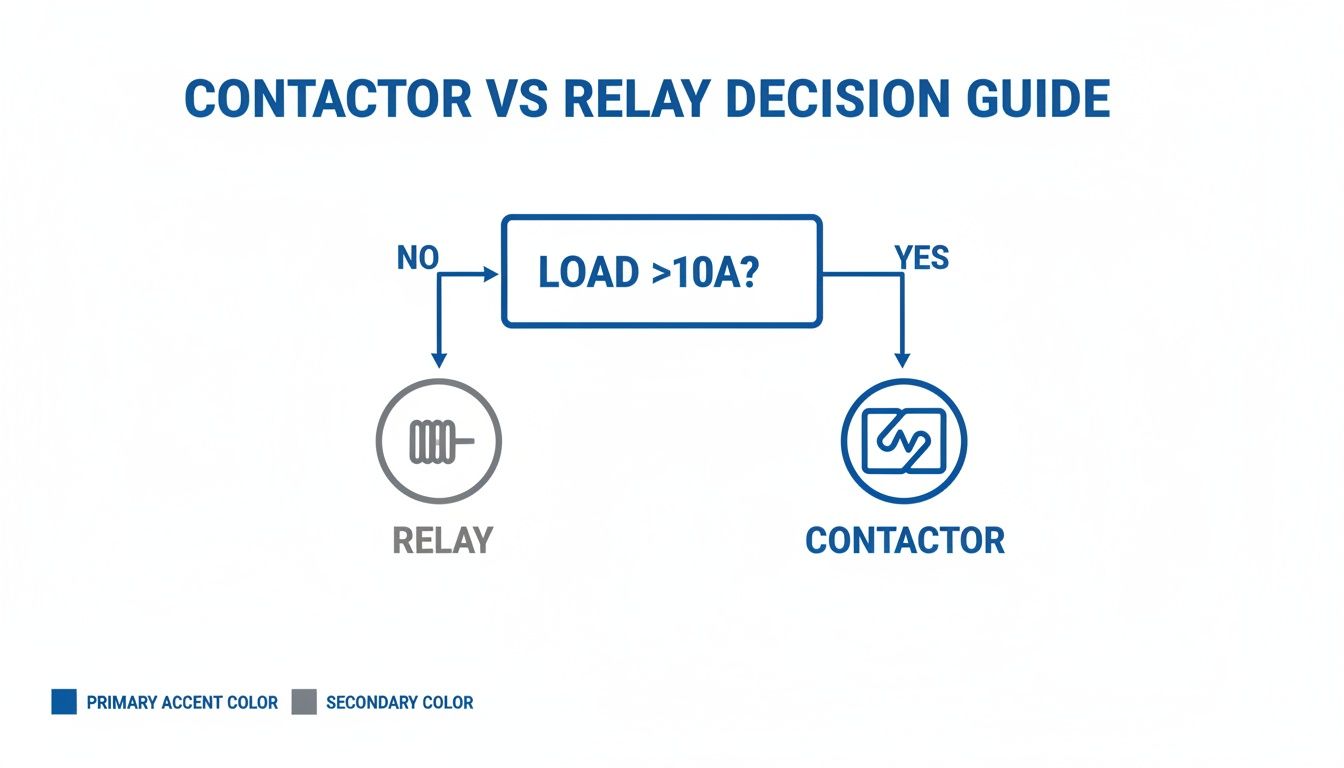
As you can see, that 10-amp line is the first major fork in the road. It immediately points you toward a contactor for power switching and a relay for control signals.
Load Characteristics
The nature of the electrical load is, without a doubt, the most important piece of the puzzle. Answering these two questions will narrow down your options fast.
- What’s the full-load amperage (FLA)? If the steady current draw is over 10A, a contactor is almost certainly the answer. Relays are best kept to loads comfortably below that mark.
- Is the load inductive or resistive? Inductive loads—think motors, transformers, or solenoids—are tough on switching components. They create huge inrush currents and nasty electrical arcs. Contactors are built for this abuse, with features like arc suppression. Relays, on the other hand, are much happier switching simple resistive loads like heaters or lights.
You can think of this choice as a risk assessment. A contactor is engineered to handle the risks that come with switching powerful, inductive loads. A relay is built for the low-risk world of signal-level logic. Using the wrong one is an open invitation to equipment failure and serious safety hazards.
System and Control Requirements
Beyond the load, you need to think about how this component fits into the bigger picture of your control system.
- What control voltage is available? Make sure the coil voltage of your device (whether it's 24VDC, 120VAC, etc.) matches the output from your PLC or whatever is driving it. Contactor coils generally need more power to pull in than relay coils, which sometimes means you’ll need a small interposing relay just to activate the contactor.
- Do you need auxiliary contacts for feedback? If your control logic needs to confirm that a motor has actually started, or if you need a signal for a safety interlock, you’ll want a contactor. They are designed with built-in or add-on auxiliary contacts specifically for this kind of feedback. While a standard relay might have multiple contacts (Form C), they aren't meant for feeding status back from a power circuit.
Operational Demands
Finally, look at the long-term operational needs to make sure the component you choose will last.
- How often will it be switching? For high-cycle applications that are turning on and off many times per minute, the heavy-duty mechanical construction of a contactor is a must if you want it to have a long service life.
- What’s the required electrical lifespan? Always check the manufacturer’s datasheet for the electrical life rating at your specific load current. A contactor is designed to survive over a million cycles switching a heavy motor, a number that a relay would never come close to in the same high-stress job.
Answering Your Lingering Questions
Even after laying out the core differences, a few common questions always pop up when it's time to apply these components in the real world. Let's tackle some of the most frequent ones to clear up any confusion and give you some practical answers for your next project.
Can I Use a Contactor Instead of a Relay?
Technically, yes. You could use a contactor to switch a tiny load that a relay would normally handle. But you really shouldn't.
It’s almost always a bad idea. The contactor will be bigger, cost more, and its coil will pull way more power than a relay's coil ever would. While it's a safe substitution, it’s not an efficient one. Using a contactor where a relay belongs is a classic case of over-engineering the solution.
What Happens If I Use a Relay to Control a Motor?
This is where things get dangerous. Putting a standard relay on a motor is a recipe for catastrophic failure, guaranteed. A relay's contacts just aren't built for the massive inrush current a motor draws at startup—often 6 to 8 times its normal running amps.
That huge surge of current creates a powerful arc that will instantly weld the relay contacts together. When that happens, you've created a nightmare scenario where the motor can't be shut off, putting both your equipment and your team at serious risk.
Never, ever substitute a relay for a contactor in a motor circuit. The lack of arc suppression and the wrong contact material will cause an immediate and unsafe failure. This is the critical difference between these two components.
What Are Auxiliary Contacts on a Contactor Used For?
Auxiliary contacts are the contactor’s sidekick. They are smaller, low-power contacts that are physically linked to the main power contacts but are electrically separate. They open and close right along with the main contacts, but they're strictly for control logic, not for switching the heavy load.
You'll see them used for a few key jobs:
- Status Feedback: Sending a signal to a PLC to confirm that the contactor has pulled in and the motor is actually running.
- Safety Interlocks: Preventing another contactor from turning on at the same time, like in a forward/reverse motor starter.
- Indicator Lights: Lighting up a lamp on a control panel to give operators a visual cue about the machine's status.
Are There Smart Contactors and Relays?
Absolutely. Intelligent versions of both have been making their way into modern industrial setups. Smart contactors, in particular, are becoming a staple in Industry 4.0 applications. They often come with built-in electronic overload protection, communication protocols like EtherNet/IP, and diagnostic capabilities that monitor current and temperature for predictive maintenance.
While you can find smart relays with advanced timing and logic functions, the push towards integrated intelligence is much stronger with contactors. It makes sense—they're protecting high-value assets like motors, so the extra insight is well worth it.
For over 50 years, E & I Sales has been the trusted partner for industrial system integrators, plant managers, and OEMs, providing not just components but complete, reliable solutions. From premium electric motors to custom-engineered UL control panels, we ensure your operations are safe, efficient, and built to last. Partner with us to standardize your equipment and accelerate your projects with confidence. Learn more about our expertise at https://eandisales.com.