
Putting together an industrial control panel isn't just a matter of connecting a few wires. You're building the very brain of an automated system. This guide is for the system integrators, plant engineers, and OEMs in the trenches, designed to pull back the curtain on the entire process.
We'll walk through the whole journey, from the initial concept and component selection all the way to passing a Factory Acceptance Test (FAT) and making sure the panel is reliable for the long haul.
The Foundation of a Great Control Panel
A well-built control panel is the backbone of any solid automation project. It’s the physical point where electrical drawings and a pile of components become a living, breathing system that’s functional, safe, and easy to work on.
For OEMs and plant engineers, getting this right means fewer headaches on-site, faster commissioning, and equipment that just works, day in and day out.
This process, from a sketch on a napkin to a fully commissioned system, has several key stages. Skipping a step or cutting a corner anywhere along the way can lead to expensive rework, blown deadlines, and even serious safety risks.
We've designed this guide to give you practical, field-tested knowledge for every phase, focusing on:
- Real-World Advice: Actionable tips pulled from actual projects, not just theory.
- Code & Compliance: Building to critical safety standards like UL 508A.
- Smarter Workflow: Pointers to help you streamline the process and sidestep common hangups.
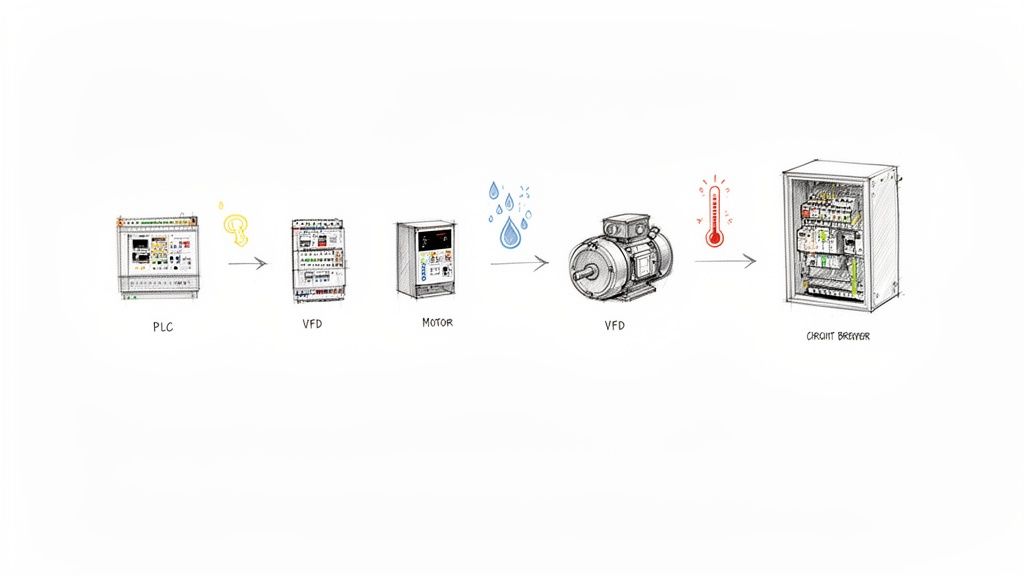
This infographic gives a great high-level view of the workflow, breaking it down into three main stages: concept, build, and commission.

As you can see, a solid plan is what makes a quality build possible, and a quality build is what ensures a smooth, efficient startup in the field.
The demand for these systems is exploding, and it’s a clear sign of a huge shift in the industry. The industrial control panels market was valued at USD 13.5 billion in 2023 and is on track to hit around USD 20.8 billion by 2032.
This isn't surprising when you see how much companies are leaning on automation to get more efficient. And if you’re looking to bring in an expert, knowing what to look for in a quality control panel builder is the perfect place to start.
Defining the Scope and Selecting Components
Every great control panel build starts long before you pick up a single tool. It begins with asking the right questions. Without a crystal-clear project scope, you're essentially flying blind, setting yourself up for expensive changes and delays down the road. A vague plan is a one-way ticket to a busted budget.
Think of it this way: you're defining the panel's entire reason for being. What machine is it running? What’s the exact I/O count for every sensor, valve, and motor? Nailing down these fundamentals is the bedrock of your design and component selection.
Groundwork Before the BOM
One of the most common rookie mistakes is forgetting about the environment. Is this panel going into a pristine, climate-controlled facility, or is it getting bolted to a machine in a washdown area where it'll see humidity and wild temperature swings? The answer changes everything, from the NEMA rating on the enclosure to whether you need an industrial air conditioner.
And then there's power. This is non-negotiable. What's the incoming voltage? What are the full-load amp (FLA) ratings for every single motor? This information is absolutely critical for sizing your breakers, contactors, and wiring correctly. Get this wrong, and you're not just risking equipment—you're creating a serious safety hazard.
As you get into the nitty-gritty, bringing safety into the conversation early is a must. A great way to do this is by understanding and implementing a risk register. This formal process forces you to identify potential electrical and mechanical hazards from the get-go, directly influencing your component choices to build a safer machine.
Making Smart Component Choices
Once you have a solid scope, you can start building your Bill of Materials (BOM). This is where the plan becomes a shopping list, and every line item is a decision that balances performance, cost, and availability.
Here’s a practical look at how these decisions play out when selecting key parts for your panel.
Key Component Selection Criteria
| Component | Selection Criteria | Best Fit Application Example |
|---|---|---|
| Motor Starter | Simple On/Off control, lowest cost, reliable for fixed-speed applications. | A basic conveyor belt that just needs to run at a constant speed. |
| Soft Starter | Reduces mechanical shock and inrush current during startup. | A large centrifugal pump where a sudden start would stress pipes and couplings. |
| Variable Frequency Drive (VFD) | Full speed control, energy savings, precise process control. | A packaging machine that needs to vary motor speed for different product sizes. |
| Programmable Logic Controller (PLC) | I/O count, memory, processing speed, communication protocols. | An automated assembly line requiring complex logic and communication with a plant-wide network. |
These are just a few examples, but they show how the application dictates the technology you need.
Take motor control. A simple conveyor might be perfectly happy with an across-the-line motor starter. But if you're building a packaging line that needs to vary its speed, a Variable Frequency Drive (VFD) is the only real answer. Somewhere in the middle is the soft starter—great for something like a large pump where you want to reduce the startup jolt but don't need full-blown speed control.
Then you have the brains of the operation: the Programmable Logic Controller (PLC). When sizing a PLC, don't just think about today. A good rule of thumb I always follow is to spec a PLC with at least 20-25% spare I/O capacity. This little bit of foresight can save you a world of pain when, a year from now, someone wants to add just one more sensor.
The real goal is to build a panel that not only works on day one but is also easy to service and adapt for years. Thinking about the future during the initial component selection is what separates a good panel from a great one.
The demand for well-engineered panels is exploding, right in line with the massive industry push toward automation. The global electric control panel market hit USD 6.37 billion in 2024 and is still climbing, all thanks to automation and grid modernization efforts. Automation panels are the fastest-growing piece of that pie, which tells you everything you need to know about where the industry is headed.
This growth means making smart component choices is more important than ever. Sticking with reputable brands known for reliability might cost a bit more upfront, but it almost always saves you money on maintenance and downtime later.
And one last pro tip: check supplier lead times early. A critical component with a 12-week lead time can completely torpedo your project schedule. This is where building solid relationships with a few good distributors really pays off—they can be lifesavers when you're in a pinch.
Designing Schematics for UL 508A Compliance
Once you have your components picked out, it's time to translate that physical plan into a detailed electrical design. This is so much more than just drawing lines on a page. You’re creating the definitive roadmap your panel shop technicians will follow to the letter.
A well-crafted schematic is, without a doubt, the single most important piece of documentation you will create for this project.
This is where safety and compliance, especially with UL 508A standards, really take center stage. These aren't just friendly suggestions; they're a hard requirement for getting your equipment to market and keeping operators safe in North America.
In fact, you can see the impact of these regulations just by looking at the market. The North American electric control panel market was valued at a cool USD 1.6 billion in 2023 and is on track to hit USD 2.8 billion by 2033. That growth is being pushed by more industrial automation and, you guessed it, strict safety rules. As the market grows, sticking to standards like UL 508A becomes non-negotiable.
The Core of Your Drawing Package
A truly complete drawing package is more than a simple wiring diagram. It’s a full-blown set of documents designed to leave zero room for guesswork. Think of it as the instruction manual for the panel's entire life, from the first wire being pulled to a maintenance call years down the road.
At a minimum, your package needs these four things:
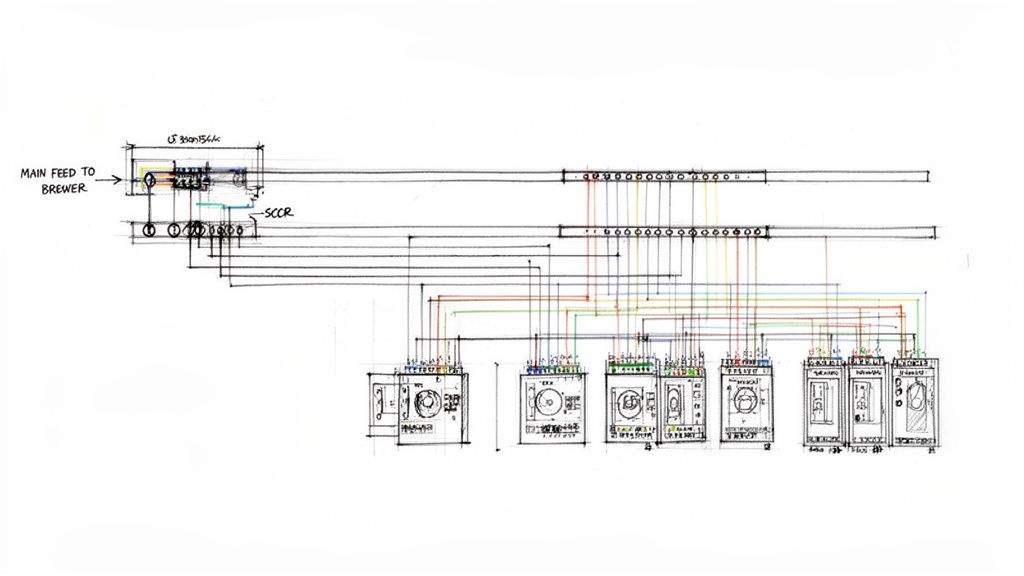
- Power Distribution Diagram: This is your 30,000-foot view. It shows how power comes in from the main disconnect and makes its way through every breaker, distribution block, and power supply to feed the whole system.
- I/O Schematics: These are the nitty-gritty pages. They detail every single PLC input and output, the device it connects to, its terminal block number, and the wire tag. This is where a tech will spend their time when troubleshooting.
- Network Layout: A clean map of your industrial network is a must. It should show how your PLCs, VFDs, and HMIs are all talking to each other. Always include device names and any critical network settings.
- Panel Layout Drawing: This is the physical blueprint, showing exactly where every component gets mounted on the back panel and door. It’s what ensures the real-world build actually matches your electrical design.
I’ve seen it a hundred times: schematics that are technically correct but practically useless. A technician shouldn't need a magnifying glass and a decoder ring to figure out what you were thinking. Use clean layouts, consistent symbols, and text that’s actually legible.
Demystifying UL 508A Requirements
Diving into UL 508A can feel like a lot, but it really boils down to a few core principles that all point back to safety. One of the most critical—and honestly, one of the most frequently misunderstood—is calculating the Short-Circuit Current Rating (SCCR).
SCCR is the maximum fault current a panel can handle without turning into a fire or shock hazard. And it’s not just about your main breaker. The SCCR of the entire panel is determined by the lowest-rated component in the power path. Every single device, from the main disconnect down to the smallest terminal block, has an SCCR value that you have to account for. Getting this calculation wrong is one of the fastest ways to get a red tag from a UL inspector.
Another big one is component spacing. Things like VFDs and power supplies throw off a lot of heat. UL 508A has specific rules for how much clearance you need around these devices to make sure air can circulate properly. Skimp on this, and you’re asking for overheated components, premature failures, or worse, a fire.
Wire Sizing and Protection
Getting your wire sizing and circuit protection right is fundamental to a safe control panel build. This is no place for guesswork. You have to select wire gauges based on the full-load amperage (FLA) of whatever you're powering, and you need to account for real-world factors like ambient temperature and how many wires are bundled together.
Every circuit needs its own properly sized fuse or circuit breaker. A classic mistake I see is using a breaker that’s way too big for the wire it's supposed to be protecting. The protector’s job is to trip before the wire turns into a toaster element during an overcurrent event.
It’s also crucial to get the different component certifications straight. To keep everything compliant, you need to understand the nuances between UL Listed vs. UL Recognized components, because they each have a specific role in the panel's overall rating. Picking the right parts and protection from the start is the foundation of a safe, reliable, and compliant panel.
Building the Panel: Mechanical Layout and Wiring
This is where the rubber meets the road—where your schematics and component lists start to look like an actual control panel. Don't underestimate this step. A thoughtful mechanical layout is just as critical as your electrical design. I’ve seen brilliantly designed circuits become a nightmare to service simply because the panel was laid out poorly.
Think of your backpanel as prime real estate. Every square inch matters.
Before you drill a single hole, lay all your major components out on the backpanel. This dry run is your best chance to see how everything fits, spot potential interference, and visualize the wiring paths. You’re looking for a logical power flow, which usually means top-to-bottom and left-to-right. Your main disconnect sits at the top, feeding power distribution blocks, which in turn supply everything else—breakers, drives, and power supplies.
Optimizing Component Placement for Longevity
Where you put things directly impacts how long they'll last. Heat is the number one enemy of electronics, so your layout is your first line of defense against it.
A hard and fast rule is to place heat-generating components like Variable Frequency Drives (VFDs) and power supplies toward the top of the enclosure. Heat rises. Placing them high allows that heat to be exhausted by fans or vents without cooking everything else in the cabinet. Putting a VFD at the bottom is a rookie mistake that guarantees you'll be replacing the PLC above it sooner rather than later.
Here’s how I approach placing the key players:
- PLC and I/O Modules: This is the brain of the operation. I like to position it centrally, keeping it as far as practically possible from high-voltage motor wiring. This separation is crucial for minimizing the electrical noise that can wreak havoc on your control signals.
- Power Supplies: Group these with other hot components near the top. Pay close attention to the manufacturer's spec sheet for required clearances. Crowding a power supply and blocking its airflow is just asking for a thermal shutdown at the worst possible time.
- Terminal Blocks: Group them logically. I create separate, clearly labeled zones for incoming power, motor outputs, and low-voltage I/O. It makes the initial wiring faster and saves massive headaches during troubleshooting down the line.
And please, plan for the future. A panel stuffed to the gills the day it’s built is a failure in planning. I always aim to leave at least 20% free space on the backpanel. The maintenance tech who has to add a new sensor six months from now will thank you for it.
Professional Wiring and Cable Management
With all the hardware mounted, it's time to run the wire. This is what separates a professional control panel build from an amateur job. The goal isn't just connecting Point A to Point B; it's creating a clean, secure, and easily traceable installation.
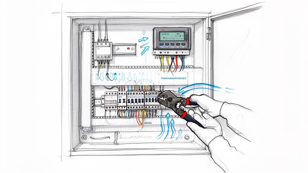
The workhorse here is the wire duct. These plastic channels are non-negotiable for a clean build. They let you route wire bundles neatly and keep the panel from turning into a rat's nest. A key pro-tip: never fill a duct more than 75% full. Overstuffing it not only looks terrible but also traps heat and makes pulling a single wire for troubleshooting nearly impossible.
Secure terminations are just as critical. A loose wire is a future service call waiting to happen.
- Proper Crimping: Use the right tool for the job. A high-quality crimper designed for the specific ferrules or terminals you're using is a must. Using pliers will get you a weak connection that will eventually fail.
- Correct Torque: Terminal blocks have torque specs for a reason. Get a calibrated torque screwdriver and use it. Over-tightening can crack the terminal, while under-tightening creates a high-resistance spot that can overheat.
- Strain Relief: Make sure any cables entering or leaving the panel are properly secured. This takes the physical stress off the terminal connections, especially for things that might get moved around like HMI pendants or remote sensors.
A panel’s quality isn't just in its function, but in its craftsmanship. When a technician opens the door five years from now, the layout and wiring should be so clear that they can understand the system's logic without needing to hunt through pages of prints.
The Critical Final Touches: Labeling and Grounding
Finally, let's talk about two things that are absolutely non-negotiable: labeling and grounding. Rushing or skipping these is one of the most expensive mistakes you can make in the long run.
Every single wire, terminal, and component needs a label. No exceptions. Invest in a good thermal transfer printer for durable wire tags that won't smudge or fall off. A clear, consistent labeling scheme that matches your schematics is the single most valuable thing you can do to speed up commissioning and future troubleshooting.
Proper grounding is the bedrock of a safe and reliable system. I always establish a central grounding point—a copper bar is ideal—and run dedicated ground wires from every single component back to it. This "star grounding" method is the best way to prevent ground loops and fight the electrical noise that can plague sensitive analog signals and communication networks.
Testing and Commissioning for a Smooth Handover
Let’s be honest: a control panel build isn't finished until it’s proven to work flawlessly. Shipping a panel without putting it through its paces is one of the biggest—and most common—gambles you can take. Trust me, discovering a simple wiring mistake on-site, with your client breathing down your neck, is a nightmare scenario. It's ten times more stressful and expensive to fix in the field than it is in your own shop.
This final phase is what separates the pros from the amateurs. Testing, documentation, and commissioning transform a collection of wired components into a bulletproof, field-ready system. It’s the final quality gate before the panel leaves your hands and the first step toward a successful project handover.
The Factory Acceptance Test: Your First Line of Defense
The Factory Acceptance Test (FAT) is your formal, in-house verification process. It's a systematic series of checks confirming the panel was built exactly to the drawings and functions as intended, before it ever leaves your facility. Think of a well-run FAT as your best insurance policy against on-site chaos.
It all starts with "dead" checks—no power allowed just yet.
- Point-to-Point Continuity: Get out the multimeter. You need to buzz out every single wire to confirm it’s landed correctly per the schematics. It’s tedious, but this one step catches the vast majority of simple wiring errors. Don't skip it.
- Insulation Resistance Test: You’ll want to megger the panel to check for shorts between conductors and from conductors to ground. This is a critical safety check to prevent a very bad, very loud surprise when you first apply power.
- Torque Verification: Grab a torque wrench and double-check every single terminal. Loose connections are a ticking time bomb and a primary cause of heat-related failures down the road.
Only when these checks are complete is it safe to move on to live power-up testing. This is where you apply control power, then main power, to check voltages, verify power supply outputs, and see the components come to life. The final piece is I/O simulation, where you manually trigger inputs and watch for the correct outputs—lights, contactor coils, etc.—to energize just as the program commands.
A detailed FAT isn't just a technical task; it's a confidence-building exercise for your client. Inviting them to witness the test demonstrates transparency and proves that you're delivering a quality product, making the final handover much smoother.
From the Shop to the Site: Seamless Commissioning
Commissioning is where the rubber meets the road. It starts the moment the panel is installed at its final destination and gets integrated with the actual machine and process. The goal here is to get from initial power-up to a fully operational system as quickly and efficiently as possible.
The final trial is the Site Acceptance Test (SAT). While the FAT often relies on simulated I/O, the SAT uses the real deal—the machine's actual sensors, motors, and actuators. This is your chance to verify motor rotation is correct, confirm every sensor is functioning, and fine-tune operational parameters like VFD speeds or timer delays.
To clarify the distinction, here’s a quick breakdown of FAT vs. SAT.
| Aspect | Factory Acceptance Test (FAT) | Site Acceptance Test (SAT) |
|---|---|---|
| Purpose | Verify panel is built and functions according to design specs. | Verify the panel and machine work together as a complete system. |
| Location | At the panel builder's shop or facility. | At the final end-user site. |
| Key Activities | Point-to-point checks, power-up tests, simulated I/O testing. | Real-world I/O testing, motor rotation checks, system tuning. |
A well-planned commissioning process, backed by a successful FAT and solid documentation, ensures the SAT is a final confirmation, not a frantic troubleshooting session. This smooth transition is the hallmark of a professional build and the key to a happy client.
The Power of a Complete Documentation Package
Once testing is complete, the final step is to assemble a comprehensive documentation package. This binder (or digital folder) is the panel's official "owner's manual." For the end-user's maintenance team, it will be an invaluable resource for years to come.
A truly great package always includes:
- As-Built Schematics: The updated drawings reflecting any redlines or minor changes made during the build.
- Bill of Materials (BOM): The final, verified list of every component, including manufacturer and part number.
- Component Datasheets: The manufacturer's technical PDFs for every major item, like the PLC, drives, and power supplies.
- Program Backups: A copy of the PLC and HMI programs on a USB drive tucked into the binder sleeve.
- FAT Report: The signed-off checklist from the Factory Acceptance Test. This is your documented proof of a successful test.
For more on building a great test plan, check out this comprehensive Factory Acceptance Test checklist guide.
Common Questions About Control Panel Builds
Even with the best plan in hand, questions are going to pop up during a control panel build. It’s just the nature of the beast, especially when you're juggling complex safety standards and a dizzying array of components.
Getting ahead of these common sticking points can save you a world of hurt—and a lot of money—down the road. So, let's jump into some of the most frequent questions we hear from engineers and clients out in the field.
What Is the Most Critical Factor in a UL 508A Control Panel Build?
This is a big one. While everything from wire gauge to terminal torque matters, the single most critical piece of the puzzle is calculating the Short-Circuit Current Rating (SCCR) correctly.
This number defines the maximum fault current your panel can handle without, well, exploding or catching fire. It is the absolute, non-negotiable foundation of any UL 508A compliant panel and is paramount for personnel safety.
Failing to calculate SCCR properly is probably the number one reason we see panels get red-flagged during a UL inspection. The process is intense; it requires you to analyze every single power component, from the main breaker all the way down to the smallest contactor. The whole panel's rating is only as strong as its weakest link.
Getting SCCR right isn't just a box-ticking exercise for an inspector. It's about making sure that if the worst happens, the panel fails in a predictable and safe way. It truly is the bedrock of your panel's entire safety certification.
How Can I Improve the Serviceability of My Control Panel Design?
Making a panel easy to work on boils down to two things: a smart, logical layout and documentation that’s crystal clear. A panel that’s a nightmare to troubleshoot is a panel that won't get maintained properly, and that means more downtime later.
Here are a few practical tips we’ve learned over the years to make life easier for the technicians:
- Leave Room to Grow: Always plan for the future. We live by a simple rule: leave at least 25% spare space on the back panel and on the DIN rails. This turns adding a new VFD or I/O slice from a full-blown rewiring project into a simple afternoon task.
- Don't Jam the Ducts: A common mistake is packing wire ducts to the brim. Try to keep them at about 75% capacity. This not only helps with heat dissipation but makes it infinitely easier for a tech to trace a wire without having to pull out the whole bundle.
- Label Everything. No, Really: Every component, every terminal block, and every single wire needs a clear, durable label. Crucially, these labels must match your electrical schematics perfectly. This creates a one-to-one map from paper to panel.
- Use Service Loops: For anything mounted on the enclosure door—like your HMI or pushbuttons—leave a generous loop of wire. This prevents strain on the terminals when the door swings open and makes swapping out a faulty button a quick fix instead of a headache.
What Are the Key Differences Between Motor Starters?
Picking the right motor starter is all about matching the hardware to the job's demands for control, efficiency, and mechanical stress. You’ve basically got three main flavors to choose from.
| Starter Type | Primary Function | Common Application |
|---|---|---|
| Across-the-Line (DOL) | The simplest option. It's just on/off control, hitting the motor with full voltage. | A basic conveyor belt that just needs to run at one constant speed. |
| Soft Starter | Ramps up voltage for a smooth, controlled start, reducing shock to the system. | A large pump or fan where a sudden DOL start would hammer the couplings or piping. |
| Variable Frequency Drive (VFD) | Controls both voltage and frequency for precise speed control during operation. | A packaging machine that has to adjust motor speed on the fly for different products or line rates. |
Think of it this way: a DOL starter is your basic light switch. A soft starter adds a dimmer for a gentle start but offers no speed control once it’s running. A VFD gives you that gentle start plus complete speed regulation, which is fantastic for process control and saving energy.
Why Is a Factory Acceptance Test So Important?
A Factory Acceptance Test (FAT) is your final quality gate before the panel ever leaves your shop. It’s your chance to validate everything in a controlled environment, and trust me, it’s far cheaper and easier to fix a wiring bug or a programming glitch at your own facility than it is on a customer's floor with their entire production team watching.
A good FAT doesn't just find problems; it provides documented proof that the panel works exactly as promised. It drastically cuts down on commissioning time, builds a ton of confidence with your client, and makes the final on-site startup a much, much smoother process.
At E & I Sales, we've spent decades mastering the art and science of the control panel build. From initial design and UL 508A compliance to rigorous testing and commissioning, our team provides the expertise to deliver reliable, code-compliant solutions for any industrial application. Learn more about how our turnkey services can accelerate your next project at eandisales.com.