
Getting the circuit breaker size right is one of those fundamental tasks that separates a reliable, safe industrial system from a problematic one. It’s a careful balancing act: the breaker's amp rating needs to be high enough to handle the normal operational current but low enough to trip before the wires overheat and create a fire hazard.
For anyone working on industrial gear—OEMs, packagers, plant engineers—this isn't just about theory. Critical details like motor inrush current and high ambient temperatures can make or break a design.
Why You Can't Afford to Get Breaker Sizing Wrong
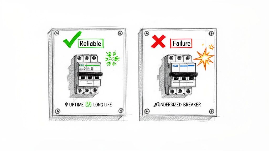
Meticulous circuit breaker sizing is far more than a simple box-checking exercise; it’s the bedrock of a dependable system. A miscalculation here creates a cascade of problems that can haunt you long after commissioning. This is about building machines and control panels that just work, day in and day out.
An undersized breaker is a constant headache. It leads to nuisance trips that kill production and send operators scrambling. On the other hand, an oversized breaker is a genuine menace. It won't protect the conductor from overheating, which is a textbook fire risk that can destroy expensive equipment and, worse, endanger your team.
The Real-World Impact on Operations
Precision here directly translates to uptime, the lifespan of your equipment, and even the profitability of a project. The demand for correctly specified components is massive. The global circuit breaker market hit USD 23.2 billion in 2024, with growth being pushed by the need for smarter, safer electrical systems.
The costs of getting it wrong are just as significant. Some studies have found that up to 30% of industrial downtime can be traced back to mismatched or poorly sized protective devices. You can find more data on the circuit breaker market on gminsights.com.
At the end of the day, a circuit breaker’s number one job is to protect the wire. Every decision you make has to flow from that single principle. If the breaker doesn’t open the circuit before the conductor’s temperature limit is breached, it has failed.
Before we dive into the nitty-gritty calculations, it's helpful to have a high-level view of the key considerations. This table summarizes the core pillars we'll be covering, acting as a quick reference guide.
Key Factors in Circuit Breaker Sizing
| Sizing Factor | Primary Consideration | Relevant Code/Standard |
|---|---|---|
| Load Assessment | Differentiating continuous vs. non-continuous loads; calculating total amps. | NEC Article 220 |
| Code Compliance | Applying the 125% rule for continuous loads and motor-specific FLC rules. | NEC Article 210, 430 |
| Conductor Ampacity | Ensuring the wire gauge can safely handle the current under its conditions of use. | NEC Table 310.16 |
| Environmental Factors | Applying derating for high ambient temperatures or multiple conductors in a conduit. | NEC Article 310.15 |
| Interrupting Rating | Confirming the breaker can safely interrupt the maximum available fault current. | NEC Article 110.9 |
| Selective Coordination | Ensuring the correct breaker trips to minimize the scope of an outage. | NEC Article 700.32 |
Each of these factors is a critical piece of the puzzle. Let's start breaking them down one by one.
Laying the Groundwork: Your Load and Conductor Foundation
Before you even think about grabbing a circuit breaker off the shelf, you have to answer a simple question: what, exactly, are you protecting? Every circuit breaker sizing job starts here, with a deep dive into the load. This isn't just about adding up amps; it's about really understanding what your equipment needs to operate safely and reliably.
This first step is what dictates your conductor size, and the two are joined at the hip. A breaker’s number one job is to protect the wire from melting down. If you don't have an accurate load profile, you're just guessing. That leads to two bad outcomes: constant nuisance tripping that kills productivity, or a catastrophic fire hazard because your breaker is too big for the wire.
Continuous vs. Non-Continuous Loads: Why It Matters
The first thing to sort out is the nature of your loads. The National Electrical Code (NEC) doesn't treat all electrical loads the same because they don't all generate the same amount of heat.
- Non-Continuous Load: Think of this as something that runs for less than three hours at a time. A small conveyor motor that cycles on and off or a temporary work light are perfect examples.
- Continuous Load: This is the big one in most industrial plants. A load is considered continuous if it's expected to run at its maximum current for three hours or more. We're talking about your big HVAC systems, workhorse air compressors, and pumps that run an entire shift without a break.
This isn't just a technicality—it fundamentally changes your math. The NEC requires you to build in a safety factor for any continuous load to handle the extra heat.
Applying the 125 Percent Rule
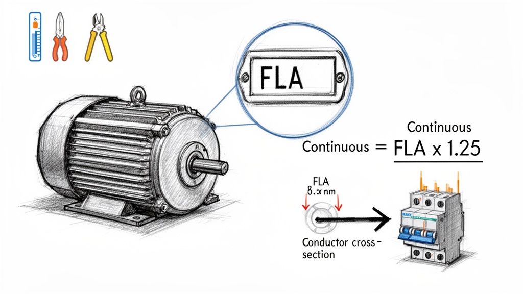
To deal with the thermal stress from equipment that runs for hours on end, NEC Article 210.19(A)(1) is crystal clear. It states that your branch circuit wires must have an ampacity of no less than 125% of the continuous load. By extension, the circuit breaker protecting that wire gets sized using the same logic.
Think of it as a built-in safety cushion. This 125% multiplier makes sure your wires and breakers aren't screaming hot at their absolute thermal limit all day long. It's one of the most common corners people cut, and it's a recipe for circuits that run way too hot and breakers that pop for no apparent reason.
Here's a quick example. Say you have a heater bank that pulls a steady 20 amps and runs all day.
You have to size your wire and breaker for at least: 20A x 1.25 = 25A
That means you're reaching for a 25A circuit breaker and picking a wire that can handle at least 25A (after you've accounted for any other derating factors, which we'll get to).
Finding Your Full Load Amps (FLA)
To do any of this math, you need real numbers. The absolute best place to get current data for any piece of equipment is its nameplate. That little metal tag is packed with gold, including the Full Load Amps (FLA)—the current a motor draws when it's doing the work it was designed for.
If the nameplate is missing or unreadable, your next best bet is the manufacturer's spec sheet or the engineering submittals. For standard three-phase motors, you can also turn to the tables in NEC Article 430 (specifically Tables 430.248, 430.249, and 430.250) to get a Full Load Current (FLC) based on horsepower and voltage. But if you have the nameplate, use it. It reflects how that specific motor actually performed in testing.
Here's a pro tip that trips up a lot of people: Always use the motor nameplate FLA for sizing your conductors and overload protection. But for sizing the breaker (the short-circuit and ground-fault protection), you have to use the NEC tables. It’s a specific nuance in NEC Article 430 that's easy to miss.
Let's walk through a real-world scenario with a small control panel.
Example: A Mixed-Load Control Panel
Imagine you're engineering a panel on a 480V/3-phase system with this equipment:
- Motor 1: A 10 HP pump motor (runs all day—continuous)
- Motor 2: A 3 HP conveyor motor (cycles on and off—non-continuous)
- Heater: A 5 kW resistive heater strip (on for hours—continuous)
First, we hunt down the FLA for each load:
- Motor 1 (10 HP): Nameplate says 14A.
- Motor 2 (3 HP): Nameplate says 4.8A.
- Heater (5 kW): We need to do a quick calculation:
(5000 W) / (480V * √3) = 6.0A.
Now we can apply the 125% rule where it's needed—only on the continuous loads.
Continuous Load Amps = (14A * 1.25) + (6.0A * 1.25) = 17.5A + 7.5A = 25ANon-Continuous Load Amps = 4.8A
By sorting our loads and doing the math correctly, we now have the real-world amperage values we need. This solid foundation is what allows us to move on to the next step: sizing our conductors properly before we pick out the final breakers.
Once you have your load calculations nailed down, it's time to get into the nitty-gritty of the National Electrical Code (NEC). This isn't just a box-ticking exercise; it’s about applying the rules correctly to build a system that's both bulletproof and reliable. Think of the NEC as the official playbook that helps us sidestep catastrophic failures and annoying nuisance trips.
You'll be spending most of your time in two key areas: NEC Article 240, which lays out the fundamentals of Overcurrent Protection, and NEC Article 430, the bible for everything related to Motors and Motor Circuits. These articles give you the roadmap to go from a calculated load to a compliant, real-world breaker.
Getting this right is a huge deal. The circuit breaker market is projected to explode from USD 25.2 billion in 2025 to an incredible USD 57.5 billion by 2035. That growth is all about the increasing need for precisely sized, reliable protective devices. For a common 50HP motor running at 460V, a simple sizing mistake can lead to much higher failure rates, turning a small oversight into a major headache.
Sizing for Motor Branch Circuits
Motors are a special breed. When they kick on, they draw a massive surge of current for a few seconds—what we call inrush current. This spike can hit anywhere from 600% to 800% of their normal running current, or Full Load Amps (FLA). If you sized a breaker just for the FLA, it would see that inrush as a dead short and trip every single time.
This is where NEC Article 430.52 comes in. It gives us permission to use specific multipliers to size a motor’s branch circuit protection (like a thermal-magnetic breaker) well above the motor's FLA.
For a typical thermal-magnetic breaker, the NEC allows you to size it up to 250% of the motor's Full Load Current (FLC) from the NEC tables. This buffer is there specifically to allow the motor to get up to speed without tripping the breaker, while still giving you solid protection against a true short circuit.
A lot of people see that 250% number and treat it like a target. It's not. It’s a maximum ceiling. Your goal should be to pick a breaker that's just big enough to handle the inrush, but as close as possible to the motor's needs to provide tighter, more effective protection.
The Critical Step: Derating for the Real World
Now we get to one of the most important—and most frequently missed—parts of sizing: derating. A wire's ability to carry current, its ampacity, isn't set in stone. It drops when things get hot or when wires are bundled together in a raceway.
These real-world conditions create heat that the wires can't shed easily. The NEC gives us correction factor tables to adjust, or derate, the wire's ampacity to account for this. And since the breaker’s entire job is to protect that wire, any reduction in the wire’s ampacity directly affects your breaker choice. You have to size the breaker to protect the wire at its final, derated value.
Dealing with High Ambient Temperatures
The ampacity values you see in NEC Table 310.16 are all based on a cozy 86°F (30°C). But if your panel is sitting in a boiler room, on a sun-baked rooftop, or anywhere the temperature regularly climbs higher, you have to apply a correction factor.
Let's say you're running 90°C-rated THHN wire in a spot that regularly hits 104°F (40°C). According to the NEC, you have to multiply its base ampacity by 0.91. Suddenly, a wire that was good for 100 amps is now only rated for 91 amps, and your breaker size has to come down to match.
Adjusting for Bundled Conductors
Heat also becomes a problem when you pack multiple current-carrying conductors into the same conduit. NEC Table 310.15(C)(1) gives us the adjustment factors for this exact scenario.
- 1-3 Conductors: You're in the clear, no adjustment needed.
- 4-6 Conductors: Reduce the ampacity to 80% of its value.
- 7-9 Conductors: Reduce it down to 70%.
The more wires you cram in there, the more you have to derate. This is also where things can get complex, as these adjustments can interact with other rules, which is something we cover in our guide on the NEC tap rule.
To illustrate, here are some common situations where derating is essential.
Common Derating Scenarios and Adjustments
| Scenario | Applicable NEC Table | Example Ampacity Adjustment | Impact on Sizing |
|---|---|---|---|
| Conductors in a hot attic (125°F / 52°C) | Table 310.16 | For 90°C wire, apply a 0.76 correction factor. | A 50A wire becomes a 38A wire, requiring a smaller breaker. |
| 5 current-carrying conductors in a conduit | Table 310.15(C)(1) | Adjust ampacity to 80% of its listed value. | A 30A circuit may now require a larger wire gauge to be protected by a 30A breaker. |
| 8 conductors in a conduit in a hot attic | Both Tables | The two factors are multiplied together (e.g., 0.76 x 0.70). | The wire's capacity is drastically reduced, demanding a much smaller breaker. |
| Solar conduits on a commercial rooftop | Table 310.16 | Ambient temperature adders may apply on top of the base temp. | This often results in significant ampacity reduction and upsizing of conductors. |
These examples show that you can't just look at the base ampacity of a wire; you have to consider the environment to select the right breaker.
A Quick Derating Example
Let's put it all together. Imagine you're pulling nine current-carrying 90°C THHN conductors through one conduit in a factory space where the ambient temperature is a toasty 110°F (43°C).
- Temperature Correction: From NEC Table 310.16, the factor for 43°C is 0.87.
- Conductor Adjustment: For nine conductors, Table 310.15(C)(1) tells us to use a factor of 0.70 (70%).
Now, just multiply these together. If we're using 10 AWG THHN wire with a base ampacity of 40A (from the 90°C column), the math looks like this:
Final Derated Ampacity = 40A × 0.87 × 0.70 = 24.36A
Even though we started with a 40A wire, under these specific conditions, its true safe capacity is only 24.36 amps. That means the largest breaker you can put on this circuit is a 20A or 25A model (depending on standard sizes). This is a perfect example of why derating isn't just a suggestion—it's the final word in getting breaker sizing right.
Mastering Short-Circuit Ratings and Coordination
Sizing a circuit breaker for predictable overloads is just the start. If you want to build a truly resilient and safe industrial system, you have to plan for the immense, destructive energy of a short circuit. This is where we move past just protecting a single wire and start thinking about system-level reliability under the absolute worst conditions.
It's easy to confuse a standard overload with a short circuit, but they're worlds apart. An overload is a slow burn—a motor struggling, a circuit drawing a bit too much current, generating heat over time. A short circuit is a violent, nearly instant surge of thousands of amps that can vaporize metal and cause catastrophic failure. Your breaker's standard trip settings are far too slow for this; you need a device that can physically withstand and extinguish that explosive arc.
Understanding Interrupting Ratings
This brings us to the Interrupting Rating, or Ampere Interrupting Capacity (AIC). The AIC is the absolute maximum short-circuit current a breaker can safely interrupt without blowing itself to pieces.
There’s one non-negotiable rule here: the breaker’s AIC rating must be higher than the available fault current (AFC) at its installation point. If the AFC at a panel is 12,000 amps and you install a breaker rated for only 10,000A (10kA), it will fail violently during a major fault. We're talking arc flash explosion potential.
Figuring out the AFC usually requires a short-circuit study, which looks at the utility transformer size, conductor lengths, and impedance. While you can often use standard values for smaller systems, a formal calculation is a must for large industrial facilities. Safety depends on it.
The Power of Selective Coordination
Once you've confirmed your breakers can survive a fault, the next step is to control how they respond. This is the whole idea behind selective coordination—a design strategy that stops a small, localized fault from triggering a widespread outage. It's the difference between a minor hiccup and a full-blown production shutdown.
The goal is simple: only the circuit breaker immediately upstream of the fault should trip. All the breakers further up the chain need to stay closed, keeping power flowing to everything else.
Think about a large control panel with a main 400A breaker feeding dozens of smaller 20A branch circuits. If a fault happens on a single 20A motor circuit, a coordinated system ensures only that 20A breaker opens. Without coordination, that same small fault could trip the 400A main, needlessly killing power to every single load in the panel.
Selective coordination is a cornerstone of reliable power system design, especially in critical facilities like hospitals and data centers where uptime is paramount. For industrial plants, it's a powerful tool to minimize costly downtime and simplify troubleshooting.
How to Achieve Coordination
Getting coordination right means digging into the time-current curves (TCCs) of your upstream and downstream breakers. These graphs show exactly how long a breaker takes to trip at any given current. For coordination to work, the entire curve of the downstream breaker has to sit below the curve of the upstream breaker, with zero overlap. This guarantees the device closest to the fault always has time to act first.
Major manufacturers provide software and tables to make this much easier. When you're designing with specific product lines, you can often just consult their published coordination tables, which show which breaker combinations are proven to work together. If you're looking for guidance on specific components, our overview of the ABB circuit breaker lineup can be a helpful starting point.
The push for these advanced protection schemes is only getting stronger. The market, valued at USD 22.13 billion in 2025, is on track to nearly double to USD 44.81 billion by 2035, driven by a 7.31% CAGR from growing electrification in manufacturing. Medium-voltage breakers, which often require careful coordination, already hold a 45% market share. Having built custom UL panels since 1974, we see this trend firsthand in the demand for smarter, better-engineered motor control centers. You can find more details in the full circuit breaker market analysis from Precedence Research.
By mastering both interrupting ratings and selective coordination, you elevate your work from basic circuit protection to thoughtful system design. This approach ensures your systems are not just safe from a short circuit’s raw power, but also smart enough to contain disruptions and keep your operations humming.
A Complete Sizing Walkthrough for a UL 508A Panel
Theory is great, but putting it into practice is where the rubber really meets the road. Let’s walk through a complete, numbers-driven sizing example for a pretty common UL 508A industrial control panel.
This scenario will tie together everything we've talked about—load calcs, derating, and the critical NEC rules—into a workflow you can actually use on your own projects.
Imagine you're engineering a control panel for a small conveyor system. The power feed is 480V/3-Phase, and the panel will live indoors where the ambient temperature can hit 104°F (40°C).
Establishing the Panel Loads
First thing's first: we have to identify every single load inside this panel. For this project, our list is straightforward:
- Motor 1 (M1): A 15 HP main drive motor, running continuously.
- Motor 2 (M2): A 5 HP auxiliary motor, also a continuous load.
- VFD: A variable frequency drive for that 15 HP motor.
- Control Transformer: A 500 VA (0.5 kVA) transformer to create our 120V control power. This is a continuous load.
Calculating Branch Circuit Requirements
Okay, now we size the protection for each individual branch circuit. We'll start with the motors, using FLC values from NEC Table 430.250 for the breakers. Just remember, conductor sizing is based on FLA (though for this exercise, we'll assume FLA and FLC are the same).
Motor 1 (15 HP drive motor)
- NEC Table 430.250 tells us the FLC for a 15 HP motor at 480V is 21A.
- For the wire, we need that 125% multiplier for continuous duty:
21A x 1.25 = 26.25A. This means we need a conductor with at least that ampacity. We'll go with 10 AWG THHN copper wire, which is good for 35A at 75°C. - For the breaker, we need to account for inrush current. NEC Table 430.52 gives us a 250% multiplier:
21A x 2.50 = 52.5A. You can't just grab a 52.5A breaker off the shelf. Per NEC 240.6, you have to round down to the next standard size. That lands us at a 50A thermal-magnetic breaker.
Motor 2 (5 HP auxiliary motor)
- The FLC for a 5 HP motor is a much smaller 7.6A.
- Conductor sizing is next:
7.6A x 1.25 = 9.5A. 14 AWG THHN wire is rated for 20A at 75°C, so that's plenty. - Breaker sizing:
7.6A x 2.50 = 19A. Here, the "next size up" rule applies, so we can safely select a standard 20A breaker.
Control Transformer (500 VA)
- First, we need the primary current:
500 VA / 480V = 1.04A. - Sizing the breaker is governed by NEC 450.3(B), which lets us size primary-only protection up to 125% of the primary current:
1.04A x 1.25 = 1.3A. A standard 2A supplementary protector is the perfect fit for this control circuit.
Sizing the Main Feeder and Breaker
With all the branches handled, it's time to size the main incoming breaker for the whole panel.
NEC 430.24 gives us the formula: 125% of the largest motor's FLC + the sum of all other motors' FLC + the sum of all other loads.
Let's do the math:
- Largest Motor Calc:
21A (15 HP motor) x 1.25 = 26.25A - Add Other Motors:
26.25A + 7.6A (5 HP motor) = 33.85A - Add Other Loads:
33.85A + 1.04A (transformer) = 34.89A
Our calculated total load comes out to 34.89A. The next standard breaker size up from that value is 40A. So, we'll spec a 40A main circuit breaker.
Applying Derating Factors
We're not quite done. The final—and crucial—step is to double-check that our conductors can handle the load under the panel's actual operating conditions.
Remember that 40°C ambient temperature? Using NEC Table 310.15(B)(1), the correction factor for our 75°C wire is 0.88. Let's check the 10 AWG wire we picked for the 15 HP motor:
Derated Ampacity = 35A (base ampacity) x 0.88 = 30.8A
Our required ampacity was 26.25A. Since 30.8A is greater than that, our 10 AWG wire is good to go. This kind of systematic process is the absolute cornerstone of safe and effective industrial control panel design.
This flowchart really brings the safety process into focus, from preventing simple overloads to coordinating protection for a major short circuit.
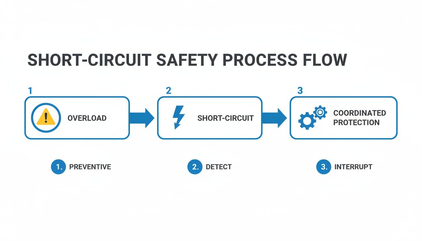
It’s a great visual reminder that robust protection is about more than just tripping on an overload. It’s a full strategy for interrupting faults safely and selectively.
The Final Sanity Check: Always, always verify your work. Does each branch breaker actually protect its conductor? Does the main breaker protect the main feeders? Are all the interrupting ratings high enough for the available fault current? This last review is what prevents expensive mistakes and ensures you're building something that's safe and built to last.
Even after you get a solid process down for sizing breakers, some questions just keep coming up. I see them all the time in the field—these are the real-world gray areas that can trip up even experienced engineers and lead to code violations or, worse, unsafe equipment.
Let's clear the air on a few of the most common ones.
Can I Just Use the Next Standard Breaker Size Up?
It’s tempting, I get it. But grabbing the next size up is almost always the wrong move.
That "next size up" rule you might have heard about, found in NEC 240.4(B), is incredibly specific and loaded with restrictions. A big one is that it generally doesn't apply to motor circuits (they have their own rules in Article 430) or any circuit over 800A.
Slapping an oversized breaker on a standard circuit is a serious fire hazard. The breaker's number one job is to protect the wire from melting down. If you round up when you shouldn't, you create a dangerous gap where the conductor can get dangerously hot long before the breaker ever thinks about tripping.
Always size the breaker to protect the wire at its final, derated ampacity. No exceptions.
What's the Difference Between UL 489 and UL 1077 Breakers?
This one is absolutely critical for anyone building industrial control panels. The two are not interchangeable.
A UL 489 Miniature Circuit Breaker (MCB) is a listed device specifically designed for branch circuit protection. Think of it as the primary, frontline defense for a circuit.
On the other hand, a UL 1077 device is just a "supplementary protector." It's only meant for use inside listed equipment, providing an extra layer of protection for sensitive components like a PLC's power supply. It simply doesn't have the muscle (the interrupting rating) to handle a true branch-level fault.
Using a UL 1077 device where a UL 489 breaker is required is a common and dangerous code violation. It creates a massive safety risk because the device was never tested or built to handle the kind of fault currents it could see at the head of a circuit.
How Should I Size a Breaker for a Variable Frequency Drive?
When you’re working with a Variable Frequency Drive (VFD), there is only one source of truth: the manufacturer's installation manual. The power electronics inside a modern VFD are incredibly sophisticated and require very specific protection.
VFD manufacturers do extensive, destructive testing to figure out the exact breaker size and type (like thermal-magnetic vs. instantaneous trip) needed to protect the drive from short-circuit damage without nuisance tripping. Just sizing the breaker based on the motor's Full Load Amps (FLA) is a recipe for failure and will likely void the drive’s warranty.
Bottom line: Always follow the VFD manufacturer's tested and approved recommendations.
For over 50 years, E & I Sales has been the partner that engineers, OEMs, and plant managers trust for reliable motor control and power distribution solutions. If you need help specifying the right components or designing a complete UL-listed control panel, our team has the expertise to deliver a safe, compliant, and robust system. Visit us at https://eandisales.com to learn more.