
Before you even think about cutting a single wire, we need to talk about why you absolutely must build a control panel to UL standards. This isn't just about getting a sticker for the enclosure door; it’s the entire foundation of safety, reliability, and market acceptance for your machinery. Following a standard like UL 508A is your first and best line of defense against risk.
Why UL Compliance Is Non-Negotiable
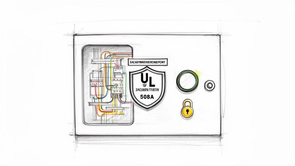
When you build a control panel, you're building the brain of a machine or an entire process. If it fails, the consequences can be catastrophic, going way beyond simple downtime. That's where UL 508A, the Standard for Industrial Control Panels, enters the picture. Think of it as a comprehensive blueprint for safety and quality assurance that's recognized and respected all across North America.
This certification isn’t a friendly suggestion—it’s frequently a hard requirement. Many jurisdictions, most insurance carriers, and countless major industrial customers simply won't allow equipment on their floor without that UL mark. For OEMs and packagers, it's a badge of quality that unlocks access to bigger and better markets.
The Foundation of Safety and Reliability
At its core, a UL 508A certification means the panel was designed and built using a proven, systematic methodology. This process validates that every single component is right for the job and that the entire assembly can safely handle its rated electrical load without a problem.
This standardized approach tackles the critical safety details that prevent disasters. We're talking about things like:
- Component Spacing: Ensuring proper clearances between parts to stop electrical arcing and manage heat buildup.
- Short Circuit Current Rating (SCCR): Verifying the panel can withstand a massive fault current without exploding or catching fire.
- Wire Sizing and Protection: Making sure every conductor is sized for its load and backed up by the correctly rated fuse or circuit breaker.
By building to these established rules, you are designing safety into the system from the very beginning, not bolting it on as an afterthought. This ensures the panel not only works on day one but keeps running safely and reliably for years to come.
Understanding the Terminology
It's easy to get lost in the jargon. You'll hear terms like "Listed" and "Recognized" thrown around, and while they sound similar, they mean very different things.
A UL Listed product is a complete, standalone item that has been tested for a specific end-use. A UL Recognized component, on the other hand, is meant to be part of a larger assembly. Knowing the difference is absolutely vital when you're selecting parts. To get the full picture, you can learn more about the crucial differences between UL Listed vs. UL Recognized components in our deep-dive guide.
A non-compliant panel isn’t just a code violation; it’s a tangible risk. It exposes operators to electrical hazards, threatens expensive machinery with catastrophic failure, and can lead to immediate project shutdowns by safety inspectors, costing thousands in lost productivity and rework.
The Real-World Costs of Non-Compliance
Let's be blunt: skipping UL standards is a high-stakes gamble you can't afford to take. Picture a new production line, ready to go, shut down completely because an inspector red-tags an unlisted panel. The cost of that downtime, plus the emergency field rework and potential re-engineering, will instantly eclipse whatever you thought you were saving.
Worse yet, if an electrical fire or accident does happen, the first thing investigators will look at is the equipment's compliance. A non-UL panel creates a massive liability for both the panel builder and the facility owner, and it could be grounds for your insurance company to deny the claim. For any plant engineer or OEM, standardizing on UL 508A panels isn't just good practice—it's a fundamental risk management strategy that protects your people, your equipment, and your company's reputation.
Your Blueprint for a Successful Panel Build
Every great control panel starts long before you pick up a single tool. It begins with a solid plan. Think of your design and documentation as the foundation of your entire project—get it right, and everything else falls into place. This is where you iron out the kinks, prevent costly screw-ups, and make sure the final panel is safe, efficient, and won't be a nightmare to maintain down the road.
Trying to jump straight into a build without a blueprint is like a contractor trying to build a house from a napkin sketch. It's a recipe for disaster. The time you spend planning upfront pays for itself ten times over by cutting down on rework, making parts ordering a breeze, and guaranteeing a smoother assembly.
And the need for well-engineered panels is only growing. The global electric control panel market was valued at a whopping USD 6.37 billion in 2024 and is expected to nearly double to USD 12.15 billion by 2034. This boom is fueled by huge investments in automation and grid modernization, which means the demand for properly documented, compliant panels is higher than ever. If you're interested in the numbers, you can dig into the full electric control panel market research.
Defining the Scope of Work
Before you even think about opening your CAD software, you need a rock-solid Scope of Work (SOW). This document is your North Star. It’s what translates a machine's operational needs into concrete technical specs, ensuring everyone—from the engineer to the wireman to the end-user—is on the exact same page.
A good SOW leaves no room for guessing. It should nail down specifics like:
- Motor Loads: List out every single motor. I’m talking horsepower (HP), full-load amps (FLA), voltage, and exactly how it will be controlled (a simple starter, a VFD, a soft starter?).
- I/O Points: Map out all your discrete and analog I/O. What kind of sensors are you using (NPN or PNP)? What signal levels do you need (4-20mA, 0-10V)? Any special communication protocols?
- Environmental Conditions: Where is this panel going to live? A clean, climate-controlled room is one thing, but a food processing plant that gets washed down daily is another entirely (hello, NEMA 4X). Don't forget to account for potentially hazardous locations.
- Power Source: What are you plugging into? Specify the incoming voltage, phase, frequency, and most importantly, the available fault current. You absolutely need this to calculate the panel's Short Circuit Current Rating (SCCR).
Getting these details right in the SOW is non-negotiable. An incomplete scope is the number one cause of mid-project change orders, and those always cost more time and money than you planned for.
Think of your documentation package as the panel’s biography. It tells the story of how it was designed, what it’s made of, and how it’s supposed to work. Without it, future troubleshooting and maintenance become a frustrating guessing game.
Creating Essential Panel Documentation
With a tight SOW, you can now build out the core documents that will guide the hands-on work. These aren't just papers to be filed away; they are the literal instruction manual for building, wiring, and commissioning the panel.
No matter the project size, there are a few foundational documents you'll always need. I've broken them down here to show why each one is so critical to getting the job done right.
Essential Documentation for Your Control Panel Project
| Document Type | Purpose and Value | Key Information to Include |
|---|---|---|
| Electrical Schematics | This is the complete wiring roadmap. It shows how every single component is electrically connected, making wiring and future troubleshooting possible. | Power distribution, control circuits, I/O wiring, component tags, wire numbers, and terminal block layouts. |
| Panel Layout Drawing | A physical map of the panel. It shows the precise placement of components on the backpanel and door for an optimal fit and function. | Component dimensions, required clearances for heat dissipation, wire duct routing, and locations for operator devices like buttons and HMIs. |
| Bill of Materials (BOM) | The comprehensive parts list. This ensures every necessary component is ordered correctly and acts as a checklist during assembly. | Manufacturer part numbers, quantities, descriptions, and component tags that cross-reference back to the schematics. |
These documents work together to form a complete picture of your control panel. A tech should be able to pick them up years from now and understand exactly what they're looking at without having to trace a single wire.
From Design to Bill of Materials
Modern CAD software is your best friend here. It’s indispensable for creating accurate schematics and layout drawings that you can trust. Good software helps you visualize component placement and, more importantly, catch common mistakes—like not leaving enough space for wire bending radii or proper airflow for thermal management. A great layout isn't just about cramming everything in; it's about building a panel that’s easy to work on for years.
Once your design is locked in, generating the Bill of Materials (BOM) is the next step. A well-structured BOM is more than just a shopping list. I always recommend organizing it logically by component type (e.g., power distribution, control, I/O). It makes purchasing far less painful and helps the assembly team stage their work efficiently. This detailed planning is what turns a digital design into a real-world, reliable control panel.
Choosing the Right Components for Reliability
The components you pick are the heart and soul of your control panel. Getting this right isn't just about making sure everything fits—it's about building a system that can take a beating day in and day out, all while staying safely within UL specifications. A truly solid panel is built with parts that are correctly sized, properly rated, and tough enough for the environment they'll live in.
It all starts with the core power and control components. Think of them as the engine and transmission of your system. If you get these right, everything else has a strong foundation to build on. This is absolutely not the place to cut corners; the reliability of your entire machine hangs on their performance.
Sizing Your Core Power Components
When you build control panel systems, it's easy to fall into the trap of oversizing "just in case." That's a waste of money. Undersizing? That's just asking for a catastrophic failure. Precision is the name of the game here, and it all begins with understanding your load—which, for most of us, means motors.
Your calculations have to be based on the motor's Full-Load Amps (FLA), not just its horsepower rating. The FLA is what the motor will actually draw under its intended load, and it's the number that dictates your protective devices.
- Circuit Breakers and Fuses: These exist to protect the wire and the motor. A good rule of thumb is to size them at 125% of the motor's FLA for standard motors, but you always need to consult the National Electrical Code (NEC) for the final word, especially when dealing with VFDs.
- Contactors and Motor Starters: These switching devices need to be rated for the specific horsepower and voltage of the motor. Don't just match the amperage; you need a contactor that can handle the inductive kick of a motor load.
- Variable Frequency Drives (VFDs): Pick your VFD based on the motor's FLA and voltage. And don't forget the duty cycle. A heavy-duty application like a rock crusher demands a much more robust VFD than a simple conveyor belt does.
Sizing everything meticulously ensures each part operates within its safe thermal limits. This simple step prevents those frustrating nuisance trips and keeps components from failing prematurely. You can dive deeper into the specifics of industrial control panel design to really dial in your component selection process.
Selecting the Brains and Nerves
Once your power distribution is mapped out, it's time for the control components. This is your PLC, power supplies, and all the wiring that ties everything together.
The PLC is your central decision-maker. The choice here comes down to the complexity of your process. How many I/O points will you need? What about communication protocols like EtherNet/IP or Modbus TCP? A simple packaging machine might get by with a micro PLC, but a complex robotic cell is going to demand a powerful controller with advanced motion capabilities.
Power supplies are the unsung heroes of any panel. A pro tip: always choose a 24VDC power supply with at least 25-30% more capacity than your calculated control load. That extra headroom accounts for the inrush current when devices first power on and gives you room to add things later without a full redesign.
Choosing components is a balancing act between performance, cost, and availability. But there's one non-negotiable: compliance. Every major component must be UL Recognized to be included in a UL 508A listed panel.
This is where a clear process comes in, moving from the initial project scope to a finalized Bill of Materials. It's the blueprint for everything that follows.
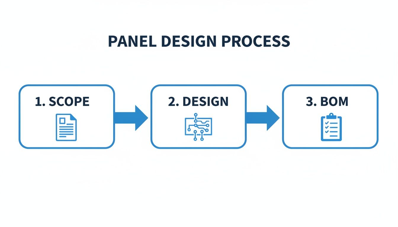
This workflow shows exactly how a detailed design phase prevents procurement mistakes and assembly delays down the road.
Enclosures and Environmental Considerations
The enclosure is your panel's first line of defense. The environment tells you what NEMA rating you need. A NEMA 12 enclosure is perfectly fine for a clean, dry factory floor. But if you’re building a panel for a food processing plant that gets high-pressure washdowns, you need a stainless steel NEMA 4X enclosure to stop corrosion and water from getting in.
Beyond just the components themselves, smart inventory management is a huge factor in project success. Having a clear view of your stock streamlines purchasing and helps you sidestep those last-minute project delays. It's a critical topic covered well in a comprehensive guide to contractor asset and inventory management.
The demand for this work is only growing. The industrial control panels market is set to jump from USD 13.5 billion in 2023 to USD 20.8 billion by 2032. With manufacturing and industrial automation applications grabbing a massive 39.6% of the market in 2024, the pressure to pick high-quality, reliable components has never been higher. This explosive growth shows why getting your component selection right isn't just a best practice—it’s a major competitive advantage.
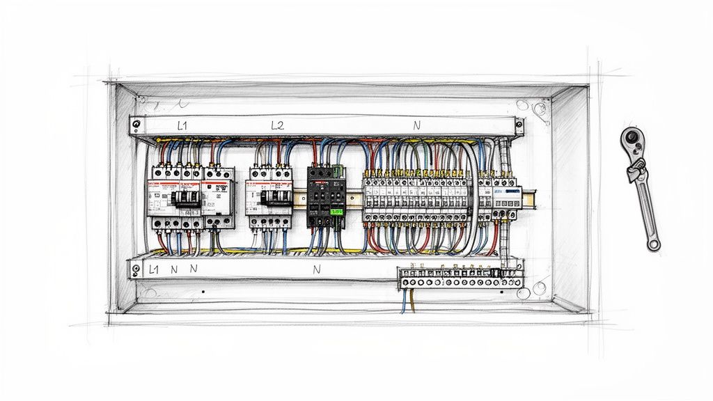
Bringing the Design to Life: Panel Fabrication and Assembly
This is where the rubber meets the road—where your carefully crafted schematics and digital layouts become a tangible, working piece of hardware. When you build a control panel, you're moving from theory to craftsmanship. A clean, well-organized build isn't just about looking professional; it's the foundation of safety, reliability, and sanity for the maintenance crew who will live with this panel for years.
The real difference between a decent panel and a great one is in the details. It's the small, deliberate choices made during assembly that prevent massive headaches down the line. This is about more than just hooking up wires; it's about building a robust system with precision and foresight.
Nail the Backpanel Layout First
Before you mount a single component, lay everything out on the backpanel. Think of this as a dry run, your last chance to catch physical conflicts before they become a real problem. Place the components according to your drawing and ask the important questions.
Is there really enough breathing room around that VFD for proper cooling? Can I actually get a screwdriver onto the terminal screws of that power supply once the wire duct is in?
A logical flow is critical. Keep your high-voltage power components—the main disconnect, breakers, and motor contactors—grouped together, typically at the top of the panel. This separates them from the sensitive, low-voltage control electronics like PLCs and I/O cards. This simple act of segregation is your first line of defense against electrical noise, a notoriously frustrating issue to chase down later.
The Craft of Clean Wiring
With components mounted, the wiring begins. The name of the game is methodical neatness. Wire duct is your best friend here, turning a potential rat's nest into clean, organized channels that protect wires and make future inspections a breeze.
A few pro wiring habits will set your work apart:
- Label Every Wire, Both Ends: This is non-negotiable. Every wire needs a unique label on each end that matches your schematics. Without this, troubleshooting turns into a painful, time-consuming process of manually tracing circuits.
- Get the Wire Length Just Right: Wires cut too short put constant strain on terminal connections, a failure waiting to happen. Wires that are too long create a tangled mess that traps heat and makes it impossible to access components.
- Keep Signals Separated: Use different wire ducts or maintain physical distance between your power (480V), control (24VDC), and communication (Ethernet) cables. Running a motor lead right next to a network cable is asking for signal interference.
A well-built panel tells a story of professionalism. When a technician opens the door five years from now, clear labels, neat routing, and solid connections are what turn a four-hour troubleshooting nightmare into a fifteen-minute fix.
Precision Where It Counts: Terminations
The physical connection points are where most panels fail. A loose connection creates resistance, which generates heat, causes intermittent faults, or can even lead to a catastrophic arc flash. This is where meticulous attention to detail pays huge dividends.
First, every stranded wire must get a ferrule. A ferrule is a simple metal sleeve crimped onto the end of a stranded wire, containing all those tiny strands and ensuring a solid, reliable connection in a terminal block. It prevents fraying and guarantees a superior connection over time. A quality crimping tool is essential to get this right.
Just as critical is applying the correct torque to every screw terminal. Component manufacturers provide torque specifications for a reason.
- Under-torqued screws create a high-resistance connection, which means heat and a potential fire hazard.
- Over-torqued screws can damage the terminal, strip the threads, or crush the conductor, leading to another kind of failure.
A calibrated torque screwdriver isn't a luxury; it's a mandatory tool for building safe, reliable panels. Documenting that terminals have been torqued to spec should be a standard step in your quality control process.
Grounding: The Foundation of Safety and Signal Integrity
Finally, let's talk grounding. A solid grounding system is the backbone of your panel's safety and your secret weapon against electrical noise. Every non-current-carrying conductive part—the backpanel, enclosure door, and component chassis—must be bonded to the central ground bus.
This means more than just running a green wire. Use dedicated grounding terminal blocks and ensure every connection is clean, bare metal-to-metal. On painted enclosures, you need to scrape away the paint where your ground lug connects. This creates a low-impedance path to earth, ensuring circuit breakers and fuses trip instantly in a fault condition. It also provides a stable reference point for your control signals, draining away the electrical noise that causes PLCs and VFDs to act erratically.
Safe Power-Up and Commissioning Protocols
This is it. The moment of truth. After all the design work, component sourcing, and careful assembly, you're ready to flip the switch. This is easily the most critical part of the entire build, and being methodical and safety-obsessed isn't just a good idea—it's mandatory. Rushing now is a sure-fire way to fry expensive components, cause major delays, or worse.
A controlled commissioning process is what separates a smooth handover from a disastrous one. It’s how you turn a static box of wires into a fully functioning, reliable system. Let's walk through the field-tested protocols that will protect your investment and make sure every circuit works exactly as planned.
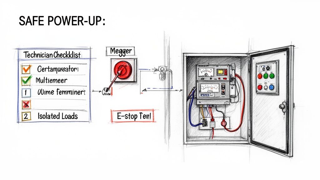
Pre-Power Safety Verifications
Before you even think about throwing that main disconnect, there’s a series of "dead panel" checks you have to perform. These are non-negotiable. They confirm the integrity of your wiring and catch any immediate faults before they have a chance to let the smoke out.
First up is the point-to-point continuity test. Get out your multimeter and your schematics and systematically check every single wire run. It's tedious, but this is how you confirm that Wire 101 actually landed on Terminal 101 and wasn't accidentally swapped with something else. This simple check is your best defense against sending 480V into a sensitive 24V PLC input.
Next, you'll perform an insulation resistance test, what we all call a megger test. By applying a high DC voltage (usually 500V or 1000V), this tool checks for any breakdown in wire insulation. It’ll immediately find pinched wires, damaged insulation, or potential shorts between conductors and the ground. A healthy panel shows incredibly high resistance, telling you everything is properly isolated.
Your pre-power checklist is your final line of defense. Finding a dead short with a multimeter is a minor inconvenience that takes minutes to fix. Finding it with 480V three-phase power is a catastrophic failure that can destroy thousands of dollars in components instantly.
Controlled Initial Power-Up Sequence
Once all the dead-panel checks are complete and signed off, you can move on to a controlled, staged power-up. The key is to energize the panel in sections, verifying each one before moving to the next. All your main loads, like motors, should still be completely disconnected at their terminals.
- Main Power Verification: Close the main disconnect and immediately measure the incoming voltage. Make sure it matches the panel's nameplate, and check all phase-to-phase and phase-to-ground voltages. You're looking for stable, correct power.
- Control Circuit Energization: Now, power up your control transformer and any 24VDC power supplies. Grab your multimeter again and verify the secondary voltages right at the terminal blocks. You should see a rock-solid 120VAC and 24VDC.
- Component Power-On Checks: Do a quick visual scan. All the components with status lights—PLCs, VFDs, network switches—should be powering on. You want to see steady "power on" lights and no red "fault" indicators. This is your basic "smoke test" to ensure nothing was DOA.
Making sure your panel has properly sized protection is a foundational part of this process. This level of electrical infrastructure planning is just as critical as designing robust data center power distribution systems for ensuring uptime. For a more detailed guide on this, check out our article on proper circuit breaker sizing to protect your gear.
Live Functional and I/O Testing
With stable control power and all your core components online, it's time for live functional testing. This is where you bring the logic to life and confirm every single input and output works as designed. It’s a good idea to have the machine operator or a process expert with you for this part.
The game here is to systematically "force" inputs and watch for the correct outputs. For instance, you’ll manually trigger a level sensor and verify that the corresponding pump contactor pulls in.
Your live testing punch list should cover:
- Discrete I/O Checks: Go through and trigger every single limit switch, push button, and sensor. Watch for the corresponding input light on the PLC card to illuminate and confirm the logic fires the right output.
- Analog I/O Scaling: For your 4-20mA devices like pressure transmitters, use a signal injector or process meter to simulate the signal. Check that the value on the HMI or in the PLC code scales correctly (e.g., 4mA reads 0 PSI, 20mA reads 100 PSI).
- Safety Circuit Validation: This is the most important test of all. Physically press every E-stop. Pull every safety pull-cord. Open every interlocked guard door. You must verify that all hazardous motion stops immediately and unconditionally. No exceptions.
- Motor Rotation Check: With every other test passed, you can finally "bump" each motor. A quick pulse of power is all you need to confirm its direction of rotation. If it's spinning backward, just shut down, lock out, and swap any two of the three-phase leads.
Running through this complete commissioning process ensures the panel isn't just built to print, but that it’s also safe, reliable, and truly ready for production.
Clearing Up Common Control Panel Questions
When you're deep in a panel build, questions always pop up, especially around compliance and best practices. Getting the right answers from the start is the difference between a smooth project and a series of expensive, time-consuming do-overs.
Let's walk through some of the most common questions we hear from engineers and technicians out in the field. Think of this as the practical knowledge you need to connect the dots between your schematics and a rock-solid, compliant panel.
What’s the Real Difference Between UL Listed and UL Recognized?
This is probably the single most important distinction to get right.
A UL Listed mark is for a complete, standalone product that's been tested for a specific purpose. Your main circuit breaker? That’s a perfect example of something that should be UL Listed. It’s a self-contained device ready for its intended job.
A UL Recognized component, however, is a part that's meant to be used inside a larger UL Listed assembly. To build a UL 508A Listed panel, you have to use these UL Recognized components according to a certified shop's specific procedures. You can't just put a UL Listed VFD into a box and call the whole thing "UL Listed." The entire, completed panel has to be certified as a system.
How Do I Figure Out the Right Enclosure Size?
Sizing an enclosure is about much more than just making sure the components physically fit. One of the classic mistakes is packing everything in too tightly, which is a recipe for overheating and early component death.
You've got to think about the details that aren't on the component's spec sheet:
- Wire Bend Radius: Big wires don't like to make tight turns. You have to leave plenty of room to bend them without damaging the conductor or violating code.
- Heat Dissipation: VFDs, power supplies, and transformers throw off a lot of heat. Without enough space for air to move, you're essentially slow-cooking your electronics.
- Room to Grow: Always plan for the future. A smart rule of thumb is to keep 25-30% of your backpanel space free for future additions or modifications.
That "empty" space isn't wasted—it's a smart investment in the panel's reliability and makes life easier for anyone who has to service it down the road. And don't guess on cooling; always do the thermal calculations to see if you need fans or an AC unit.
The most common mistakes in a panel build often come down to the small details: improper grounding creating electrical noise, inconsistent wire labels making troubleshooting impossible, and failing to torque terminal connections to spec, which can lead to arcing and catastrophic failure.
What Are the Most Common Panel Building Mistakes?
Besides getting the enclosure size wrong, a few other common slip-ups can really compromise a panel's safety and function.
The number one problem we see? Inconsistent or missing wire labels. It seems small, but it turns a five-minute troubleshooting job into an all-day nightmare of manually tracing circuits.
Another big one is improper grounding. Get this wrong, and you can introduce electrical noise that causes PLCs and other sensitive gear to act erratically. And finally, failing to manage heat with proper ventilation is a direct path to components failing way sooner than they should.
At E & I Sales, we bring over 50 years of hands-on experience to designing and fabricating custom UL-listed control panels that meet the absolute highest standards. Let us help you build your next control panel right the first time.