Let’s cut through the jargon. At its core, variable speed is about giving a motor a gas pedal instead of just an on/off switch.
Think about driving your car with the accelerator floored, using only the brake to control your speed—that’s basically how a traditional fixed-speed motor works. Variable speed technology is the game-changer that lets you dial in the motor’s speed to perfectly match the demands of the job, saving a ton of energy and reducing wear in the process.
Unlocking a Smarter Way to Run Motors
For decades, most industrial electric motors ran on a simple, brute-force principle: all or nothing. They were either off or roaring at full throttle, with zero middle ground. This fixed-speed approach is dead simple and reliable, but it’s incredibly inefficient for any application where the workload isn't constant.
To control the output, you had to rely on clunky mechanical devices like dampers, valves, or gears. It was a crude method, basically like driving with one foot slammed on the gas and the other on the brake to manage your speed.
Variable speed technology completely rewrites that playbook. By adding a smart controller, usually a Variable Frequency Drive (VFD), operators can fine-tune a motor's output with surgical precision. This isn't just a minor tweak; it’s a fundamental shift in how we manage industrial power and processes.
From Brute Force to Finesse
That old fixed-speed method wastes an unbelievable amount of energy. When a pump or fan only needs to run at 70% capacity, forcing it to go full blast and then mechanically choking its output is like trying to run a marathon in ski boots. Sure, you’ll get there, but you’ll burn way more energy than you needed to.
Variable speed control puts an end to that waste. It makes sure the motor only pulls the exact amount of power it needs to meet the current load. This simple concept leads to some massive advantages that are driving its adoption everywhere:
Serious Energy Savings: By matching motor speed to real-time demand, facilities can slash motor energy consumption by 20-50%, sometimes even more.
Tighter Process Control: Precise speed adjustments mean better product quality, less wasted material, and more nimble production lines that can adapt on the fly.
Reduced Mechanical Stress: Gentle starts and stops, often called soft-starting, get rid of the jarring electrical and mechanical shock of a direct-on-line start. This extends the life of everything from the motor itself to the belts, couplings, and gears connected to it.
A VFD gives a standard motor the intelligence to operate at its most efficient point for any given task. This is what moves industrial systems from a state of constant over-performance to one of optimized, demand-based operation.
To give you a quick visual, here’s how the two approaches stack up.
Fixed Speed vs Variable Speed At a Glance
This table breaks down the core differences between the old-school fixed-speed systems and modern variable speed setups. It highlights just how much more control and efficiency you gain.
Characteristic
Fixed Speed Systems
Variable Speed Systems
Speed Control
None. Runs at a single, constant speed.
Infinitely adjustable across a wide range.
Energy Efficiency
Low, especially at partial loads.
High, as power use is matched to the load.
Process Control
Crude. Relies on mechanical throttling.
Precise and responsive.
Mechanical Stress
High. Full-voltage starts are harsh on equipment.
Low. Soft starts reduce shock and wear.
Operating Cost
Higher due to wasted energy.
Lower due to significant energy savings.
As you can see, the move to variable speed is less of an upgrade and more of a complete evolution in motor control.
The impact of this technology is undeniable when you look at its market growth. The global VFD market is on track to jump from USD 23.85 billion in 2025 to USD 40.97 billion by 2034. That kind of growth underscores its vital role in modern industrial efficiency. You can dig deeper into these trends in this detailed VFD industry report.
How a Variable Frequency Drive Makes It All Happen
To really get what "variable speed" means in practice, you have to look inside the box—the Variable Frequency Drive (VFD), which is the brains behind the whole operation. A VFD isn't magic; it’s a sophisticated piece of power electronics that runs a three-stage conversion process to give you pinpoint control over a motor.
Think of it as a translator for electricity. It takes the raw, inflexible power from the utility grid and reshapes it into a new, custom-tailored electrical signal designed for one job: telling your motor exactly how fast to run.
This technology really took off during the industrial automation boom of the 1980s, but its roots go back to the 1970s oil crises. When global energy costs shot up by over 400%, the glaring inefficiency of just running motors at full blast all the time became a very expensive problem to ignore. If you're interested in the history, you can review industry intelligence on drive technology to see how it evolved.
The Three-Stage Power Conversion Process
The journey from a fixed AC input to a variable AC output happens in three distinct steps inside every VFD. Each stage has a critical job in molding the electricity into the perfect shape for precise motor control.
The Rectifier (AC to DC): First up, the VFD grabs the standard alternating current (AC) from your wall outlet and funnels it into a rectifier. This section is filled with diodes, which act like one-way gates for electricity. They effectively chop off the negative half of the AC sine wave, converting it into a rough, pulsating direct current (DC).
The DC Bus (Smoothing Things Out): This raw, bumpy DC isn't clean enough to work with yet. So, it flows into the DC bus, which is essentially a bank of large capacitors. These capacitors act like tiny, fast-acting batteries, soaking up the peaks and filling in the valleys of the pulsating DC. The result is a smooth, stable, and clean DC voltage.
The Inverter (DC Back to a New AC): Here’s where the real magic happens. The smooth DC power is sent to the inverter. This stage uses incredibly fast switches (transistors, usually IGBTs) that flicker on and off thousands of times per second. By chopping up the DC voltage in a very specific pattern, they build a brand-new, synthetic AC waveform from scratch to send to the motor.
This diagram shows you exactly how that three-step process flows, turning fixed utility power into a controllable output.
It’s a clear picture of how the VFD acts as the middleman, taking a fixed input and producing a totally variable output through its internal AC-to-DC-to-AC conversion.
Building the Perfect Wave with PWM
So how does the inverter turn a flat DC line into a beautiful, usable AC sine wave? It uses a clever trick called Pulse Width Modulation (PWM).
Creating a perfect, smooth AC sine wave electronically is complicated and expensive. Instead, the inverter fakes it by generating a rapid-fire series of rectangular DC pulses that have different widths.
It’s a bit like trying to draw a perfect circle using only tiny, straight Lego bricks. If you use enough small, carefully placed bricks, the final shape looks remarkably circular. PWM is the electronic version of that.
The VFD's inverter switches on and off so quickly, creating thousands of tiny voltage pulses. By precisely controlling the width and timing of these pulses, it builds a waveform that looks and acts like a true AC sine wave to the motor, letting it run smoothly at any frequency you command.
This method is stunningly efficient and gives the drive incredible control over both the frequency (speed) and voltage (torque) going to the motor. Want the motor to run slower? The VFD just creates the pulses at a lower frequency. Need more speed? It increases the frequency.
This elegant electronic sleight of hand is the core of how variable speed control becomes a practical, powerful reality in the real world.
The Top 3 Reasons to Make the Switch to Variable Speed
Let's get straight to it. Moving from a fixed-speed "all or nothing" motor to one with variable speed control isn't just a minor tweak—it's a fundamental shift in how your facility operates. The decision pays off in some seriously powerful ways, with benefits that show up everywhere from your monthly utility bill to the lifespan of your most critical machinery.
It really boils down to three game-changing advantages.
Benefit 1: Massive Energy Savings
If there's one reason that gets everyone's attention, it's the huge drop in energy consumption. Think about a fixed-speed system. The motor is either on or off, always running at full tilt, no matter the actual workload. To control the output, you're stuck using mechanical dampers or valves to choke the flow. It’s like flooring the gas pedal in your car while riding the brake to control your speed. Inefficient is an understatement.
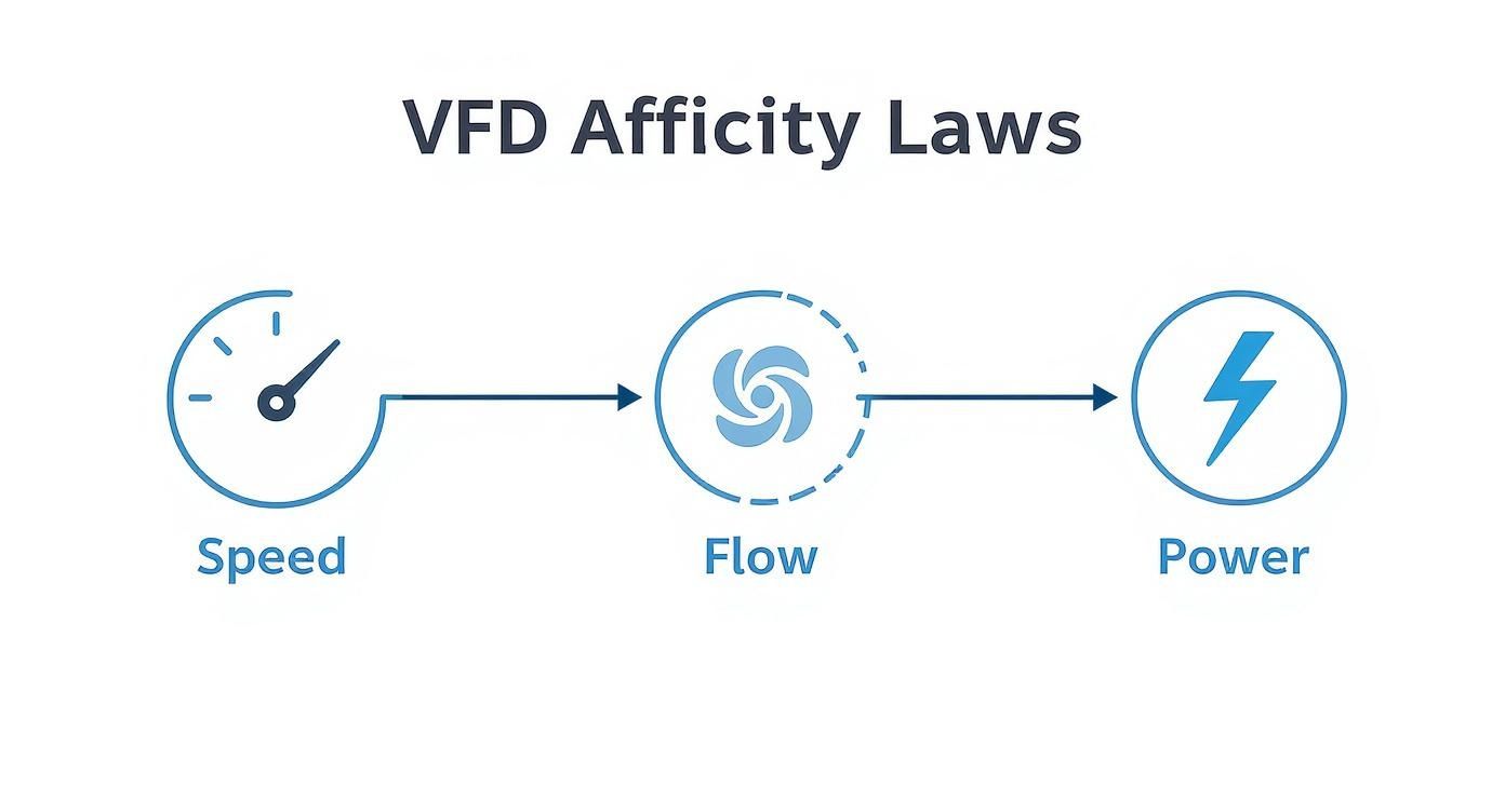
Variable speed control flips the script by perfectly matching the motor's power draw to what the load actually needs in real-time. This is a massive deal for pumps and fans, where a simple rule of physics known as the Affinity Laws comes into play.
The Affinity Laws are an engineer's best friend. They tell us that the power a fan or pump needs is tied to the cube of its speed. This creates an exponential relationship—a small drop in speed leads to a massive drop in power use. For example, slowing a fan down by just 20% can slash its energy consumption by nearly 50%.
That's the magic. Instead of wasting energy by running a motor at 100% and throttling it, a VFD just slows the motor down. The result? We regularly see energy consumption drop by 20-50%. That’s a direct hit to your operating costs and a big win for your carbon footprint. You can dig deeper into the numbers with our guide on calculating VFD energy savings.
Benefit 2: Fine-Tuned Process Control
Energy savings are great, but the precision you gain with variable speed is what transforms your entire operation. Fixed-speed systems are blunt instruments. Variable speed gives you a scalpel.
Picture a bottling plant conveyor. A fixed-speed motor means one speed, all the time. If production needs change, you're stuck. There’s no agility.
Now, add a VFD into the mix. Suddenly you can:
Synchronize multiple production lines to completely eliminate bottlenecks and pile-ups.
Dial in mixer speeds to get the perfect consistency every single time, whether you're making chemicals or cake batter.
Control pump flow rates with incredible accuracy for precise dosing and blending.
This level of control means less wasted material, a higher-quality final product, and a far more flexible manufacturing floor. You can finally adapt on the fly without ever compromising your standards.
Benefit 3: Less Wear, Tear, and Maintenance
Every time a standard motor fires up, it's a violent event. A direct-on-line (DOL) start unleashes a huge inrush of current—often 600% or more of the motor's normal rating. This slams the system with a sudden jolt of torque. It's the mechanical equivalent of getting rear-ended, and it happens every single time you start up.
This repeated shock brutalizes every component down the line, from motor windings and shafts to belts, couplings, and gearboxes.
This is where a VFD's "soft start" capability really shines. It gently ramps up the motor’s speed and voltage, completely eliminating that electrical surge and mechanical shock. This smooth, controlled acceleration dramatically reduces the stress on all your equipment.
The payoff is huge. Less stress means a longer life for your machinery, fewer surprise breakdowns, and way lower maintenance costs over the long haul. You're not just buying a drive; you're buying reliability.
Where Variable Speed Control Really Shines
Theory is great, but seeing how variable speed control works in the real world is where the lightbulb really goes on. This isn't some niche lab technology; it's the workhorse behind the scenes in countless industries, quietly saving money, tightening up processes, and improving final products everywhere from factory floors to high-rise office buildings.
The core idea is simple: match the motor's speed to the actual job at hand. Whether you're running a manufacturing line or a municipal water pump, ditching the old "all-or-nothing" fixed-speed approach for precise control is a total game-changer.
Let's look at a few places where this tech makes a massive difference.
Making HVAC Systems Smarter
Heating, Ventilation, and Air Conditioning (HVAC) systems are probably the most common and impactful place you'll find variable speed drives. Think about a big commercial building—the cooling and heating needs are all over the place during the day, changing with the number of people inside, the weather, and the time.
The Old Way: A fixed-speed fan or pump motor would just run at 100% power, all the time. To control the temperature, the system used mechanical dampers—basically metal flaps that block the vents. It's like flooring the gas in your car and using the brake to control your speed. Incredibly inefficient.
The VFD Way: With a VFD, the fan motor can just… slow down. When demand is low, instead of running at full tilt and fighting itself, the system simply dials the motor back to maybe 40% speed. Because of a principle called the Affinity Laws, that small drop in speed creates a massive drop in energy use. We're talking 30-50% savings on HVAC energy bills, easy.
Taming the Chaos of Conveyor Systems
In any factory or warehouse, conveyor belts are the lifeblood of the operation. They move products from A to B, and keeping that flow smooth is absolutely critical for preventing jams, damaged goods, and costly downtime.
A fixed-speed conveyor line is just asking for trouble. If one belt runs just a tiny bit faster than the one feeding it, you're going to get pile-ups and chaos. With variable speed control, each motor can be tuned perfectly to sync up with the others. This creates a single, seamless production line that can speed up or slow down in unison. That's the foundation of modern automation. If you want to dig deeper into how this works for specific motors, we have a great guide on AC motor variable speed control.
By enabling precise synchronization, variable speed control transforms a series of isolated machines into an intelligent, integrated production line. This eliminates guesswork and manual adjustments, leading directly to higher throughput and reduced waste.
Nailing the Perfect Mix, Every Time
When you're making food, pharmaceuticals, or specialty chemicals, consistency is king. Industrial mixers and extruders need exact speed control to get the texture, viscosity, or chemical reaction just right for every single batch.
A fixed-speed mixer is a blunt instrument. It's either on or off, which can mess up product quality or even ruin a whole batch if the mixing is too rough. Slap a VFD on there, and suddenly the operators have real control. They can:
Program custom mixing profiles with different speeds for different stages of the process.
Tweak the speed in real-time if the material gets thicker or thinner.
Use a gentle soft-start to keep expensive ingredients from splashing out.
This isn't just a nice feature; it's mandatory for meeting today's tough quality standards. And this thinking extends beyond the factory floor, too. You can see similar principles at play in cutting-edge fields like the latest innovations in electric propulsion for boats, where precise speed control is essential for efficiency and maneuverability.
How to Select and Integrate the Right VFD System
Picking the right VFD goes way beyond just matching horsepower ratings. If you want a system that's reliable, safe, and built to last, you need to think about the whole package—from the motor it’s controlling to the panel it lives in.
Getting these details right from the start is the difference between a smooth-running machine and a maintenance headache waiting to happen.
Let's walk through the big-ticket items you need to nail down to avoid common traps and spec a VFD system with confidence.
Ensuring Motor and Drive Compatibility
This is ground zero. Your first job is to make absolutely sure the motor is designed to play nice with a VFD. While you can technically run almost any AC induction motor with a drive, slapping one on a standard motor is just asking for a premature failure.
The rapid-fire voltage pulses from a VFD's output can chew through the winding insulation on a standard-duty motor. That’s why you always, always pair a VFD with an inverter-duty motor. These motors have beefed-up insulation systems built specifically to handle the electrical stress. It's the single best investment you can make for reliability.
Managing Heat Inside the Control Panel
VFDs are powerful pieces of electronics, and they throw off a surprising amount of heat. A drive can lose 2-3% of its throughput power just as heat. If that heat gets trapped inside a sealed control panel, temperatures can skyrocket, cooking sensitive components and dramatically cutting the VFD's lifespan short.
You can't afford to ignore thermal management. The basics include:
Proper Sizing: Give the drive some breathing room. A cramped enclosure is a hot enclosure.
Ventilation: Use filtered fans to create airflow, pulling in cool ambient air and pushing out the hot stuff.
Air Conditioning: For hot environments or panels packed with gear, a dedicated panel air conditioner is often the only way to keep electronics in their happy place.
Addressing Electrical Harmonics
Drives are what we call "non-linear loads." Instead of drawing power in a nice, smooth sine wave, they pull it in short, choppy bursts. This creates electrical "noise" on your power system called harmonics. Too many harmonics can wreak havoc, from overheating transformers to tripping breakers and messing with other sensitive equipment.
Think of harmonics as electrical pollution. One VFD might not be a big deal, but a dozen of them on the same system can poison your power quality and affect the entire facility.
A simple and effective first line of defense is a line reactor. It’s an inductor installed on the input side of the VFD that helps smooth out the current draw, cutting down on distortion. For tougher situations or where power quality standards are strict, you’ll need to explore more advanced options and learn about the different harmonic filters for VFDs to keep your system clean and stable.
The Importance of UL Panels and Proper Enclosures
Safety and compliance aren't optional. Specifying a UL-listed control panel (typically certified to UL 508A) is your assurance that the entire assembly was built to strict, nationally recognized safety standards. This isn't just a "nice-to-have"—it's often demanded by customers, insurers, and inspectors.
Finally, the box itself is your VFD's first line of defense against the real world. Choosing the right NEMA-rated enclosure is critical.
NEMA 1: Good for clean, dry, indoor spots.
NEMA 12: Keeps out dust, dirt, and dripping liquids.
NEMA 4/4X: Built for washdown duty, protecting against direct water spray. The 4X adds corrosion resistance for harsh environments.
To help tie all this together, here’s a practical checklist to run through when you’re specifying your next VFD package.
VFD Selection Checklist for Industrial Applications
Consideration Area
Key Questions to Ask
Why It Matters
Motor Compatibility
Is the motor rated for inverter duty? What is the motor's full-load amperage (FLA) and voltage?
Standard motors will fail prematurely. Matching electrical specs ensures the VFD can properly control and protect the motor.
Load Characteristics
Is it a variable torque (fan/pump) or constant torque (conveyor) load? Are there high starting torque requirements?
This determines the drive's required overload capacity (e.g., 110% for VT vs. 150% for CT) and influences sizing.
Thermal Management
What's the maximum ambient temperature? How much space is in the enclosure? Are other heat-producing devices nearby?
Overheating is a leading cause of VFD failure. Proper cooling (fans, AC) is non-negotiable for ensuring a long service life.
Power Quality
How many other VFDs are on the same transformer? Are there strict power quality requirements (e.g., IEEE 519)?
Prevents harmonics from disrupting other equipment in your facility and avoids potential utility penalties.
Enclosure & Environment
Will the panel be indoors or outdoors? Exposed to dust, moisture, or corrosive chemicals? Is it a washdown area?
The NEMA rating must match the environment to protect the electronics from contamination and damage.
Safety & Compliance
Does the application require a UL 508A listed panel? Are there specific customer or site-wide safety standards to meet?
Ensures the system is safe, insurable, and compliant with regulations, providing peace of mind and reducing liability.
By thinking through these areas from the start, you move from simply buying a drive to engineering a complete, reliable variable speed solution.
Keeping Your VFDs Healthy: Maintenance and Troubleshooting
Getting your variable frequency drive installed is just the beginning. To make sure it’s pulling its weight for years to come, you need a solid plan for its entire lifecycle. Think of it as three key pillars: a smart commissioning process, consistent maintenance, and knowing how to troubleshoot when things go wrong. These are what stand between you and costly downtime.
A great VFD implementation always starts with a careful, methodical startup. This is where you program the drive’s brain, telling it exactly how to manage the motor and its load. You’ll be setting crucial parameters like the acceleration and deceleration ramps, which guarantee smooth starts and stops that don't put unnecessary stress on your mechanical systems.
Another non-negotiable step is running a motor auto-tune. This clever function lets the VFD “get to know” the unique electrical personality of the motor it’s connected to. It builds a precise mathematical model, which allows the drive to dial in its output for the best possible performance and efficiency. The result is rock-solid control under any condition.
A Simple Preventive Maintenance Checklist
Once you're up and running, a simple preventive maintenance routine is your best friend. It’s all about catching the small stuff before it snowballs into a full-blown failure. Consider it a quick health checkup for one of your most critical pieces of equipment.
A proactive approach doesn't need to be a huge time-sink. Here are the essentials:
Look Around: Do regular visual checks for any signs of overheating, like discolored plastic or burnt-looking wires. Make sure all the connections are snug—vibration has a nasty habit of working them loose.
Keep It Clean: Dust is the enemy of all electronics. Every so often, power down the unit and give the VFD’s heat sinks and cooling fans a good cleaning. Proper airflow is vital to preventing overheating, which is hands-down one of the biggest causes of drive failure.
Check the Vitals: When the system is running normally, take a moment to check and log key data points like input voltage and output current. If you see these numbers start to drift from the baseline, it could be an early warning of a problem with the motor or the power coming in.
Proactive maintenance isn't a cost—it's an investment in uptime. A VFD that's kept clean, cool, and secure is a reliable VFD. Spending a few minutes on an inspection can easily save you hours or even days of lost production.
A Field Guide to Common Fault Codes
Even with the best maintenance, a VFD will occasionally throw a fault code to tell you something’s up. These codes aren’t just annoying alarms; they're diagnostic clues pointing you in the right direction. Knowing what the most common ones mean is the first step to getting back online fast.
Common Fault Code
Likely Cause(s)
First Troubleshooting Steps
Overcurrent (OC)
A sudden change in load, a short circuit, or accelerating way too fast.
Look for a mechanical jam; increase the acceleration time; inspect motor wiring for shorts.
Overvoltage (OV)
Regenerative energy from a high-inertia load, or stopping too abruptly.
Increase the deceleration time; you may need to add a dynamic braking resistor.
Undervoltage (UV)
The incoming power supply is unstable or just experienced a momentary dip.
Check that the input voltage is within the VFD's specified range; look for loose power connections.
By getting comfortable with these basic startup, maintenance, and troubleshooting steps, you can dramatically improve the reliability of any system that depends on variable speed technology. This knowledge helps you protect your investment and keep your operations running smoothly.
A Few Common Questions About Variable Speed Drives
When you start digging into variable speed technology, a few practical questions always pop up. Let's clear the air on some of the most common ones so you can make the right call for your equipment.
Can I Just Slap a VFD on Any Old Motor?
Technically, you can connect a VFD to a standard, off-the-shelf motor, but it’s a gamble you’ll probably lose. Standard motors simply weren't built to handle the unique electrical stress from a VFD's high-frequency voltage pulses. That stress chews through the winding insulation, leading to a much shorter, unhappier life for your motor.
The right way to do it is to always use an inverter-duty motor. These are built for the job, with beefed-up insulation systems that can take the heat from a VFD day in and day out. It's the only way to guarantee a long, reliable service life.
What's the Real Difference Between a VFD and a Soft Starter?
This one trips a lot of people up, but it's pretty simple. A soft starter has exactly one job: to gently ramp a motor up to its full, fixed speed. That's it. It’s a smooth on-ramp to the highway, preventing the massive electrical jolt of a direct start. Once the motor is at speed, the soft starter’s work is done.
A VFD, on the other hand, is the whole dashboard. It gives you that same gentle start, but it also lets you control the motor’s speed at any point. Think of it this way: a soft starter is just the on-ramp; a VFD is the gas pedal, the brake, and the cruise control all rolled into one.
How Much Energy Can I Actually Save?
For fans and pumps, there's a handy guideline called the Affinity Laws that gives you a surprisingly accurate estimate. These laws show that the power a motor uses is tied to the cube of its speed.
That relationship has a massive impact. It means a tiny reduction in speed delivers an outsized drop in energy consumption. For example, slowing a fan by just 20% (to 80% speed) can slash its energy use by nearly 50%. It’s one of the most powerful arguments for VFDs.
What's This "Harmonics" Thing I Keep Hearing About?
Harmonics are basically electrical noise—a distortion VFDs can introduce back into your facility's power grid. Think of them as unwanted ripples in an otherwise smooth electrical current. A single small VFD probably won't cause any trouble, but if you have a bunch of them running, that noise can add up.
When do you need to worry? If that distortion gets too high, it can cause real problems, like overheating transformers or tripping sensitive electronics. You’ll want to look at harmonic mitigation when VFDs make up a big chunk of your building's total electrical load or if you need to meet strict power quality standards like IEEE 519.
At E & I Sales, we don't just sell parts; we engineer complete, UL-listed control panels that get the job done right. From picking the perfect motor to commissioning the entire system, we build reliable, code-compliant packages designed to perform. Let us help you build your next project with confidence.
At its most basic, an electric motor control system is the collection of hardware and software that tells a motor what to do. Think of it as the brains and nervous system that turns raw electrical power into precise, controlled work. It dictates everything from when a motor kicks on to how fast it spins.
The Brains Behind the Brawn
Electric motors are the undisputed workhorses of industry. In fact, they’re responsible for over 40% of global electricity consumption. But on their own, they're just brute force—little more than a simple on/off switch. A motor control system is what refines that raw power, giving it purpose, intelligence, and a crucial layer of safety. It's the conductor of an industrial orchestra, ensuring every motor plays its part perfectly.
Picture a massive conveyor system in a distribution center. Without a control system, every motor would slam on at once with a jarring jolt, which is a great way to damage products and put immense stress on the machinery. They'd also run at a single, constant speed, guzzling energy even when the workload is light.
Why Control Is Non-Negotiable
Proper motor control brings order to this potential chaos. Instead of a violent, abrupt start, a soft starter can gently ramp up the conveyor’s speed, saving the belts and gearboxes from unnecessary wear and tear. Even better, a Variable Frequency Drive (VFD) can adjust the speed based on the actual volume of packages, which can slash energy costs.
A well-designed electric motor control system does more than just start and stop a motor; it optimizes performance, protects expensive assets, and ensures the safety of personnel. It's the critical link between raw power and productive output.
This control goes way beyond just speed. These systems are absolutely essential for:
Safety and Protection: They constantly monitor for overloads, short circuits, and overheating, ready to automatically shut down the motor before a catastrophic failure can happen.
Operational Precision: For things like CNC machining or robotics, they deliver the exact speed and torque needed to perform incredibly intricate tasks with repeatable accuracy.
Energy Efficiency: By matching the motor's output to the real-time load demand, control systems can cut electricity use by up to 50% in some applications.
Ultimately, these systems are what transform a simple motor from a dumb component into an intelligent, responsive, and efficient part of a much larger automated process.
Understanding The Core Components
To really get a handle on electric motor control systems, you need to peek inside the control panel. Think of it like the engine bay of a car—it's a collection of specialized parts all working together to turn a simple command into controlled, powerful motion. Each component has a specific job, whether it’s distributing power or fine-tuning speed with incredible precision.
Let’s break down the essential hardware that keeps modern industrial operations running. Getting to know these core elements is the first real step toward designing, maintaining, and getting the most out of any motor-driven process.
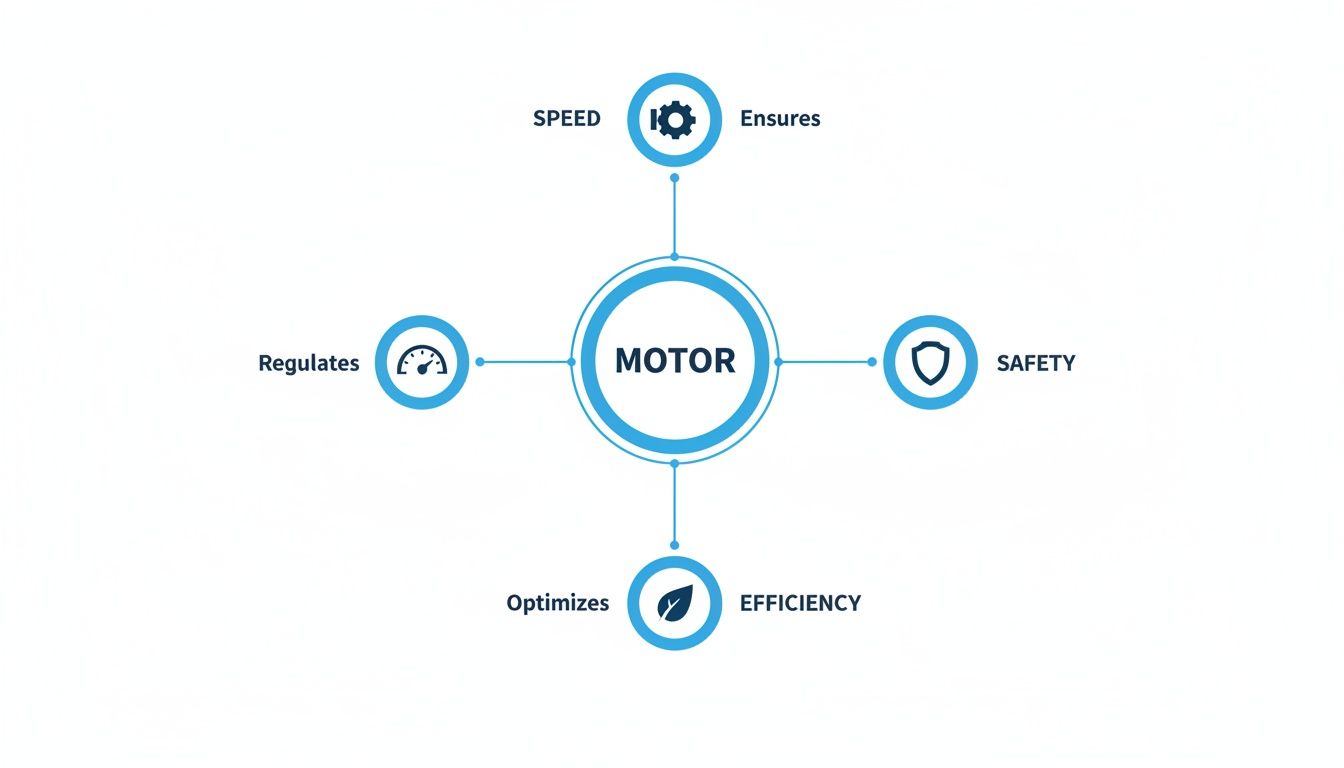
The visual below shows how a control system juggles a motor's three primary functions: speed, safety, and efficiency.
As you can see, motor control isn't just one single action. It's a balanced strategy to regulate performance while protecting the equipment and keeping energy costs down.
The Command Hub: Motor Control Centers
At the heart of many industrial facilities, you'll find the Motor Control Center (MCC). An MCC is the central nervous system for all the motors in a plant or a specific area. It consolidates starters, protective devices, and control wiring into a single, organized enclosure. Instead of having dozens of separate control boxes scattered across the floor, an MCC gives you one place for control and maintenance.
This centralization is a massive win for both safety and efficiency. It’s no surprise the global market for MCCs is growing so quickly—it's expected to jump from USD 6.73 billion in 2026 to a forecasted USD 11.94 billion by 2035. This growth is a direct result of the automation boom in industries where experts like E & I Sales deliver engineered UL panels and integrated motor control systems.
The Gatekeepers: Motor Starters
The most fundamental piece of the puzzle is the motor starter. Its main job is simple but absolutely critical: to safely energize and de-energize a motor. It acts as a gatekeeper, connecting the motor to the power source and—just as importantly—disconnecting it during an overload or fault to prevent costly damage.
There are a few different kinds of starters, but they all rely on two key parts:
Contactor: This is an electrically-operated switch that physically opens and closes the power circuit to the motor. You can think of it as the muscle of the starter.
Overload Relay: A smart protective device that senses when the motor is drawing too much current. It signals the contactor to open the circuit and shut the motor down before it can overheat.
When you're digging into control system hardware, it’s also important to understand the components they're controlling, like the various three and single phase electric motors that pair with different starter technologies.
The Accelerator: Variable Frequency Drives
If a starter is a basic on/off switch, then a Variable Frequency Drive (VFD) is the system's accelerator pedal. A VFD gives you precise, continuous control over a motor's speed by adjusting the frequency of the electrical power it receives. This capability is a total game-changer for both process control and energy savings.
For example, on a pump or fan, a VFD can slow the motor down when demand is low instead of just running it at full blast all the time. That small adjustment can slash energy consumption by 50% or more, delivering a quick return on investment. If you want to dive deeper into how they work, check out our guide on the basics of Variable Frequency Drives.
A VFD transforms a fixed-speed motor into a variable-speed asset. This allows operations to perfectly match motor output to process demand, eliminating wasted energy and enabling a level of precision that a simple starter cannot achieve.
The Shock Absorber: Soft Starters
So, what if you don't need full speed control but want to avoid the mechanical shock of a motor slamming on at full power? That's where a soft starter comes into play. It provides a smooth, gradual ramp-up to full speed, acting like a shock absorber for both your mechanical and electrical systems.
A soft starter gently increases the voltage to the motor during startup. This reduces the massive inrush of current and lessens the physical jolt on belts, gears, and couplings. This is especially useful for equipment like conveyor belts or large pumps, where an abrupt start can cause serious wear and tear over time. By managing only the startup and shutdown, a soft starter offers a cost-effective way to extend equipment life without the full feature set (and cost) of a VFD.
The table below breaks down the key differences to help you decide which technology fits your needs.
Motor Starter Technology Comparison
Control Method
Primary Function
Best Application
Key Benefit
Direct-On-Line (DOL) Starter
On/off control with overload protection.
Simple, fixed-speed applications like small pumps or fans where start-up torque isn't an issue.
Simple, reliable, and low-cost.
Soft Starter
Ramps motor voltage up/down for a smooth start and stop.
Conveyors, large fans, and pumps where reducing mechanical stress is the main goal.
Extends equipment life and reduces electrical strain during startup.
Variable Frequency Drive (VFD)
Full control over motor speed and torque at all times.
Complex processes requiring precise speed control, like HVAC systems, mixers, or machine tools.
Maximum energy efficiency and ultimate process control.
Ultimately, choosing between a starter, soft starter, or VFD comes down to what your application truly demands. Do you need simple on/off, a gentle start, or complete control over the entire speed range? Answering that question is the key.
How to Design the Right Control System
Choosing the right electric motor control system isn’t like picking a part off a shelf. It’s more like drafting a blueprint for your plant's long-term success. A well-designed system goes far beyond matching horsepower ratings—it’s a strategic decision that touches everything from operational reliability and energy bills to employee safety.
The goal here is to build a solution that nails today's demands while being tough enough for whatever you throw at it tomorrow. That whole process starts with a serious look at the application itself. Before you even think about a single component, you have to understand the job the motor is being asked to do. Getting this right from the start saves you from costly headaches down the road.
Analyzing Your Application and Load
First things first: you need to get intimately familiar with the motor's workload, or what we call its load characteristics. Not all loads are created equal, and this analysis is what dictates the type of control you'll need.
Think of it like choosing an engine for a vehicle. A sports car and a dump truck both have engines, but they’re engineered for completely different jobs. You wouldn't put a Ferrari engine in a dump truck and expect it to haul gravel effectively.
Ask yourself these critical questions about your application:
What's the torque demand? Does the load require a massive kick of starting torque, like a fully loaded conveyor belt? Or does the torque demand ramp up with speed, like with a centrifugal pump?
Do I need speed control? Is the process something that needs to run at different speeds, or is a simple on/off, fixed-speed operation good enough?
How often will it start and stop? A motor that cycles hundreds of times an hour needs a much different control strategy than one that runs continuously for days on end.
Answering these questions honestly prevents you from over-engineering with an expensive VFD when a simple starter would do the trick, or under-engineering a system that’s just going to burn out under pressure.
Defining Operational and Environmental Needs
Once you’ve got a handle on the load, the next step is to map out the operational requirements and the environment the system will live in. This is where you translate the real-world physical demands into concrete electrical and mechanical specs.
You’ll want to consider these factors:
Speed and Torque Control Precision: How tight does the speed control need to be? A simple exhaust fan might be fine with a 5% variance, but a CNC machine or a robotic arm could require precision within a fraction of a percent.
Stopping Method: Does the motor need to coast to a stop, brake hard (dynamic braking), or hold its position firmly once it’s stopped?
Environmental Conditions: Where is this control panel going to live? A hot, dusty factory? A corrosive chemical processing area? Or a clean, climate-controlled room? The enclosure rating (like NEMA 12 or 4X) has to match the environment to protect the sensitive electronics inside.
Ignoring the operating environment is a common—and expensive—mistake. A control panel built for an office setting won't last long on a factory floor exposed to washdowns and metal dust. That's a direct path to premature failure and unplanned downtime.
Proper system design isn't just about day-one performance; it's about endurance. Factoring in environmental stressors and operational demands ensures your investment is protected and your process stays reliable for years.
The push for smarter, more robust motor controllers is accelerating, driven by everything from industrial automation to the EV revolution. The global market was valued at USD 37.99 billion in 2026 and is projected to skyrocket to USD 181.29 billion by 2035, growing at an incredible 18.8% CAGR.
Ensuring Compliance and Future-Proofing
Finally, a truly great design has to meet safety standards and be easy to maintain for years to come. This is where compliance and good documentation become absolutely non-negotiable.
UL 508A certification for industrial control panels is the gold standard here. It’s a sign that the panel has been designed and built to meet strict, nationally recognized safety standards. This isn't just a sticker on a box; it’s peace of mind for inspectors, insurers, and your own team that the system is safe to operate.
Just as critical is solid documentation. This should always include:
Electrical Schematics: The detailed wiring diagrams that show how every single component is connected.
Bill of Materials (BOM): A complete parts list, including manufacturer and model numbers.
Panel Layout Drawings: A visual map showing the physical arrangement of components inside the cabinet.
This packet of documents is your roadmap for any future troubleshooting, maintenance, or upgrades. Without it, a simple component replacement can turn into a painful, time-consuming investigation.
By centralizing components in a well-documented assembly like a Motor Control Center, you make managing and upgrading your systems way easier. For a deeper dive, check out our guide on what a Motor Control Center is and see how it can streamline your operations.
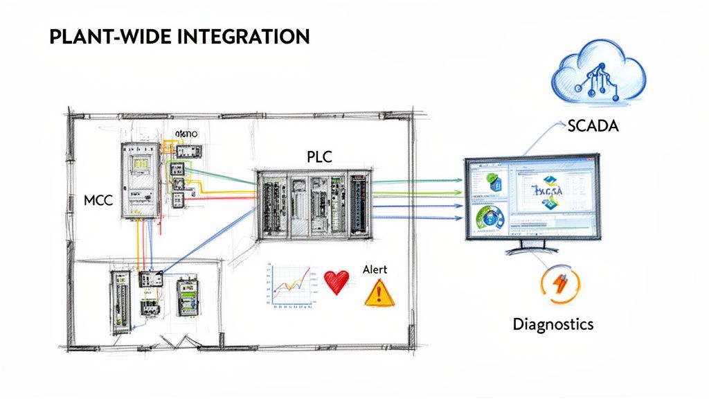
Integrating Controls with Plant-Wide Automation
An electric motor control system is powerful on its own, but its real value is unlocked when it stops being an isolated island of technology. Modern industrial plants thrive on data and connectivity. Tying your motor controls into the bigger automation network is what turns a bunch of individual components into a single, intelligent system that works together.
Think of it this way: a standalone motor starter is like a single musician playing an instrument. They might be skilled, but they have no idea what the rest of the orchestra is doing. Integrating that starter into a Programmable Logic Controller (PLC) network is like giving the musician a headset to hear the conductor and the whole symphony. Suddenly, timing is perfect and everything is in harmony.
This integration connects your motors to the facility's central brain, creating a single source of truth for your entire process. It’s how you get to the next level of efficiency, visibility, and control.
Connecting to PLCs and SCADA Systems
The most common way to do this is by linking your Motor Control Centers (MCCs) and Variable Frequency Drives (VFDs) straight to a PLC. This connection usually happens over standard industrial communication protocols.
EtherNet/IP: This is a popular one because it uses standard Ethernet technology, so most IT and engineering teams are already comfortable with it.
Modbus TCP/IP: An open protocol known for being simple and reliable. You see it a lot when connecting all sorts of different industrial electronics.
PROFIBUS/PROFINET: A really robust standard, especially common in manufacturing and process automation, particularly in facilities running Siemens gear.
Once they're connected, the PLC can send start/stop commands, tell a VFD what speed to run at, and—most importantly—get a constant stream of data back from the motor controls. That information usually gets displayed on a Supervisory Control and Data Acquisition (SCADA) system, giving operators a live dashboard of the entire plant's health.
The Power of Diagnostic Data
This is where the real magic happens. A modern "smart" MCC or VFD does a lot more than just report if it's on or off. It feeds back a ton of diagnostic info that you can use to spot trouble and prevent failures before they bring a line down.
By integrating motor controls with automation platforms, you shift from a reactive maintenance model ("fix it when it breaks") to a proactive, predictive one ("fix it before it fails"). This single change can drastically reduce unplanned downtime and maintenance costs.
Instead of guessing, your team gets hard data on things like:
Current Draw: Is a motor working harder than it should? That could point to a mechanical problem, like a bearing that’s about to fail.
Operating Temperature: A motor running hot might mean a ventilation issue or that a winding failure is on the horizon.
Run-Time Hours: You can schedule maintenance based on how much a motor has actually been used, not just based on a date on the calendar.
Fault Codes: When something does trip, you get a specific code explaining why. This lets technicians find the root cause in minutes instead of hours.
For facilities in logistics and manufacturing, this data-driven approach is essential. It's the foundation for more advanced systems, like fully integrated Automated Storage And Retrieval Systems (ASRS), which depend on this level of connectivity to work.
The demand for these integrated systems is plain to see in the market's growth. The global electric motor market was valued at USD 212.96 billion in 2025 and is projected to hit USD 405.67 billion by 2033. A huge part of that growth is driven by the push for smarter automation and better efficiency. It really just highlights how critical intelligent motor control has become for any operation trying to stay competitive.
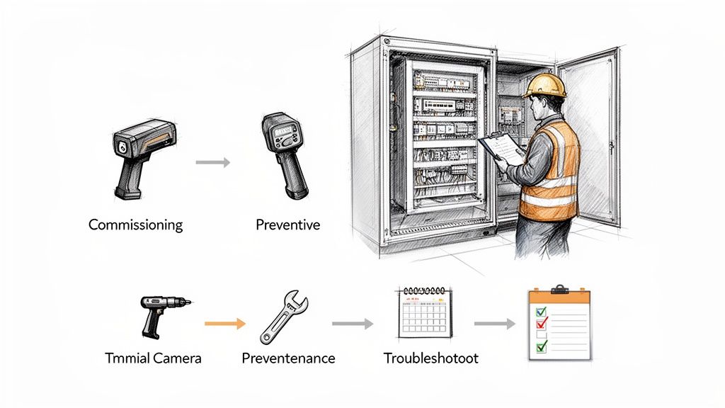
Best Practices for Maintenance and Troubleshooting
Getting a state-of-the-art electric motor control system installed is really just the starting line. If you want to get the most out of that investment, you need a solid plan to keep it running reliably for its entire lifespan. This means ditching the old "fix it when it breaks" mentality and embracing a proactive strategy for commissioning, maintenance, and troubleshooting.
A smart approach to the system's lifecycle does more than just prevent headaches. It minimizes costly unplanned downtime, extends the life of your most critical components, and keeps your whole operation humming at peak efficiency. It turns your control panels from mysterious black boxes into predictable, manageable assets. This journey begins the second the installation is finished, starting with a meticulous commissioning process.
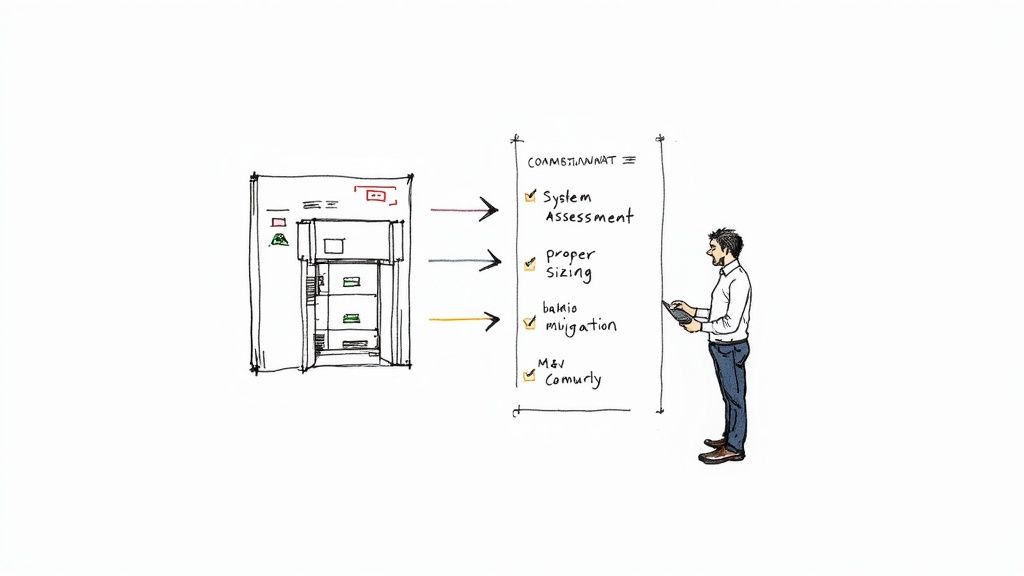
The Commissioning Checklist: Your Guarantee for a Smooth Start
Think of commissioning as a systematic shakedown of your new system. It's the process of verifying that everything was installed correctly and performs exactly as designed before you put it into full production. Skipping steps here is a recipe for disaster down the road. A comprehensive commissioning plan is your final, non-negotiable quality check.
Your process should always hit these fundamental stages:
Pre-Power Checks: Before a single volt goes through the system, get hands-on. Physically confirm that all the wiring matches the electrical schematics. Check that every terminal connection is torqued to the manufacturer's spec. Make absolutely sure all grounding and bonding is buttoned up correctly. This is your best and easiest chance to catch simple mistakes that could cause major damage.
Initial Power-Up and Configuration: Once the physical checks are done, it's time to energize the system. Go through it methodically—verify control power, check input voltages, and carefully program the essential parameters into devices like VFDs and overload relays. This includes inputting motor nameplate data and dialing in the right protection settings.
Performance and Safety Validation: With the system live, you need to test its functionality under controlled conditions. "Bump" the motors to confirm they're spinning in the right direction. Test every I/O signal to make sure it's communicating correctly. Critically, verify that all safety circuits, especially emergency stops, function flawlessly. Finally, run the system through its operational sequences to ensure it meets all performance requirements.
Building a Proactive Preventive Maintenance Schedule
Once your system is up and running, the focus shifts to preventive maintenance (PM). A good PM schedule is all about catching small issues before they snowball into major, production-stopping failures. It’s the difference between a scheduled check-up and emergency surgery.
Preventive maintenance is the single most cost-effective strategy for maximizing the reliability and lifespan of electric motor control systems. It turns maintenance from an unpredictable expense into a manageable operational cost.
Your PM schedule should be built around routine inspections and data collection, focusing on the most common points of failure. Key activities should include:
Thermal Imaging: Use an infrared camera to scan your control panels. You're looking for hot spots on connections, contactors, and circuit breakers. An unusually high temperature is a classic early warning sign of a loose connection or a component on its way out.
Connection Integrity: Periodically re-torque all your power and control wire terminations. The constant vibration and temperature swings in an industrial plant can cause connections to loosen over time, creating resistance and dangerous heat.
Environmental Cleaning: Keep the inside of your panels clean and free of dust and grime. Dust can act as an insulator, preventing proper cooling, and if it's conductive, it can lead to short circuits. Make sure all ventilation fans and filters are clean and working properly.
Component Inspection: Do a visual check of contactors for any signs of pitting or wear on the contacts. Listen for any unusual humming or buzzing from transformers and relays—these sounds can often signal an impending failure.
A Practical Troubleshooting Guide for Common Issues
Even with the best maintenance plan, problems will pop up. When they do, a logical, step-by-step approach to troubleshooting is your best friend for minimizing downtime. Instead of random guessing, arm your team with a structured plan to quickly diagnose and fix the usual suspects.
Here’s a quick-and-dirty guide for tackling common problems:
Problem
Potential Cause
Troubleshooting Steps
Nuisance Tripping
Overload setting is too low, voltage is fluctuating, or a mechanical issue is causing a high motor current.
Check the overload settings against the motor's nameplate data. Monitor incoming voltage for sags or spikes. Inspect the mechanical load for any binding or obstructions.
Motor Overheating
Poor ventilation, incorrect VFD parameters (like the V/Hz pattern), or it's simply being overloaded for too long.
Make sure the motor's cooling fans are clean and clear. Review the VFD settings to ensure they match the motor and application. Measure the motor current to confirm it's within its rated limits.
VFD Fault Code
Could be anything from overvoltage and undervoltage to an external fault signal.
Grab the VFD manual and look up the specific fault code. Check the input power quality. Inspect all motor and control wiring for loose connections or shorts.
By combining a meticulous commissioning process with a disciplined maintenance schedule and a logical troubleshooting framework, you ensure your electric motor control systems remain the reliable backbone of your operations.
Finding the Right Partner for Your Project
Let's be honest, navigating the world of electric motor control systems is a huge undertaking. From picking the right components and designing the architecture to satisfying UL inspectors and integrating everything into your plant, it's a lot to handle. The success of any project—whether it’s swapping out a single control panel or building a new facility from the ground up—really boils down to the expertise of the team you've got in your corner.
This is where having a single, dedicated partner really shines.
Instead of trying to be the ringmaster for a circus of different vendors for motors, controls, and engineering, you get one unified team focused on your outcome. It simplifies communication and gets rid of the logistical nightmares that come from juggling multiple contacts and purchase orders.
The Value of a Single-Source Expert
A true partner does more than just ship boxes. They take ownership of the entire project, from concept to commissioning. It’s a holistic approach that ensures every piece of the puzzle—the VFD, the motor, the PLC, the wiring—all fits together exactly as it should.
Here’s what that looks like in the real world:
Guaranteed Compliance: A good partner knows the code inside and out. They make sure every panel is designed and built to strict standards like UL 508A, giving you certified equipment you can trust. No more worrying about failed inspections.
Seamless Integration: They have the deep-seated knowledge to get your motor controls talking flawlessly with your existing PLCs, SCADA systems, and even the main power distribution gear. It just works.
Standardized Solutions: By bringing a consistent design philosophy to your facility, they make life easier for your maintenance team. Think simplified troubleshooting, a smaller spare parts inventory, and less downtime.
This strategy dramatically cuts down on project risk. You catch potential problems on the drawing board, not during a high-pressure startup with everyone watching.
Choosing a single-source partner turns a project from a bunch of separate purchases into a cohesive, engineered solution. It’s the difference between buying parts and investing in a system built for long-term performance.
At the end of the day, the right partner becomes an extension of your own team. They bring years of practical, in-the-field experience to the table, making sure your system isn't just designed well, but is also tough, easy to maintain, and ready for whatever you throw at it next.
With decades of experience, a dedicated industrial automation system integrator can help you tackle every challenge, from the initial spec sheet to flipping the switch. When you put your project in the hands of one accountable expert, you're building on a foundation of quality that will pay you back for years.
A Few Common Questions We Hear
When you're knee-deep in planning a new system or trying to troubleshoot an old one, a few practical questions always seem to pop up. Let's tackle some of the most common ones we hear from engineers and plant managers in the field.
What's the Real Difference Between a Soft Starter and a VFD?
The easiest way to think about it is specialization versus versatility.
A soft starter is a specialist. Its one and only job is to give a motor a gentle, smooth ramp-up to full speed, kind of like an electrical shock absorber. This is a lifesaver for reducing mechanical stress on equipment like conveyor belts or pump systems during startup.
A Variable Frequency Drive (VFD), on the other hand, is the multi-tool of motor control. Yes, it can also provide a smooth start, but its real superpower is continuous speed control throughout the motor's entire run time. This gives you the power to fine-tune your process on the fly and can lead to some serious energy savings, especially in applications with changing loads.
Why Should I Care About UL 508A Certification for a Control Panel?
That little UL 508A sticker is way more than just a label—it's your independent proof of safety and quality. It confirms that the industrial control panel was built and designed to meet the strict safety standards set by Underwriters Laboratories.
Basically, it's a third-party guarantee that the panel is wired correctly, its components are rated properly for the job, and it meets the National Electrical Code (NEC). For any facility manager, this certification is a must-have for passing inspections and, more importantly, for the peace of mind that your people and your facility are safe.
When Does It Make Sense to Go with an MCC Instead of Individual Starters?
A Motor Control Center (MCC) is your best bet whenever you have a group of motors clustered in the same general area of your plant. Instead of having a bunch of separate starter boxes bolted to walls and columns all over the place, an MCC pulls all that power distribution, control, and protection into one clean, organized cabinet.
This centralized approach makes a huge difference. It simplifies the initial install, makes routine maintenance far more efficient, and takes the guesswork out of troubleshooting. If you're managing more than just a handful of motors, an MCC gives you a standardized, scalable, and safer foundation to build on.
Can I Actually Upgrade My Old Motor Controls to Something Modern?
You absolutely can. In fact, retrofitting older or obsolete motor control systems is one of the most effective upgrades you can make. Swapping out old components for modern intelligent overload relays, soft starters, or VFDs can deliver a surprisingly fast and substantial return on your investment.
These kinds of upgrades don't just improve energy efficiency. They give you much tighter control over your process and unlock a ton of diagnostic data you can use for predictive maintenance. A good systems integrator can take a look at your current setup, pinpoint the best opportunities, and map out an upgrade path that fits your goals and your budget.
Ready to modernize your system or design a new one from scratch? The experts at E & I Sales provide engineered UL-listed control panels and turnkey integration services, ensuring your project is reliable, compliant, and efficient right from the start. https://eandisales.com
Think of a Variable Frequency Drive (VFD) as a smart throttle for your electric motors. Instead of running a motor at 100% speed all the time and using a mechanical valve or damper to choke the output, a VFD fine-tunes the motor's speed to match the exact demand of the moment. This simple but powerful principle is why VFDs consistently slash electricity consumption by 20% to 50% in the right applications.
Why VFDs Are a Must-Have for Industrial Energy Savings
Let's get practical and move past the textbook definitions. The old way of controlling motors in facilities with pumps and fans is just plain wasteful.
Imagine driving your car by flooring the gas pedal while simultaneously riding the brake to control your speed. You’d burn through a tank of gas in no time. That’s precisely what happens in a system where a motor runs full-tilt against a partially closed valve or damper. All that energy is just wasted as heat and noise.
A VFD completely flips that script. It gives you a precision accelerator for your motor, allowing it to ramp up or down to deliver only the power needed. This fundamental shift is the key that unlocks massive VFD energy savings.
The Sheer Scale of the Opportunity
The potential impact here is huge. Electric motors are the workhorses of industry, guzzling around 70% of all industrial electricity. This makes them the single biggest target for efficiency upgrades.
By intelligently matching motor output to the actual load, VFDs can take a serious bite out of that number. For instance, in common pump and fan systems, a seemingly small 20% reduction in motor speed can cut energy use by nearly 50%.
This guide will walk you through the science, the financial math, and the real-world best practices for putting VFDs to work. We'll cover everything from the basic principles to the common mistakes that can chip away at your return on investment.
Core Benefits of VFD Implementation
Installing VFDs delivers a lot more than just a smaller utility bill. The advantages ripple across your entire operation.
Drastic Energy Reduction: The most obvious win. VFDs directly cut kilowatt-hour (kWh) consumption by eliminating the wasted energy from running at a fixed, full speed.
Improved Process Control: Precision speed adjustments give you tighter control over your process, often leading to better product quality and more consistent system performance.
Reduced Mechanical Stress: The "soft start" capability of a VFD means no more jarring, across-the-line starts. This gentle ramp-up reduces wear and tear on motors, belts, and bearings, making your equipment last longer.
Lower Maintenance Costs: Less mechanical abuse means fewer breakdowns and lower maintenance spend over the life of the equipment. It’s that simple.
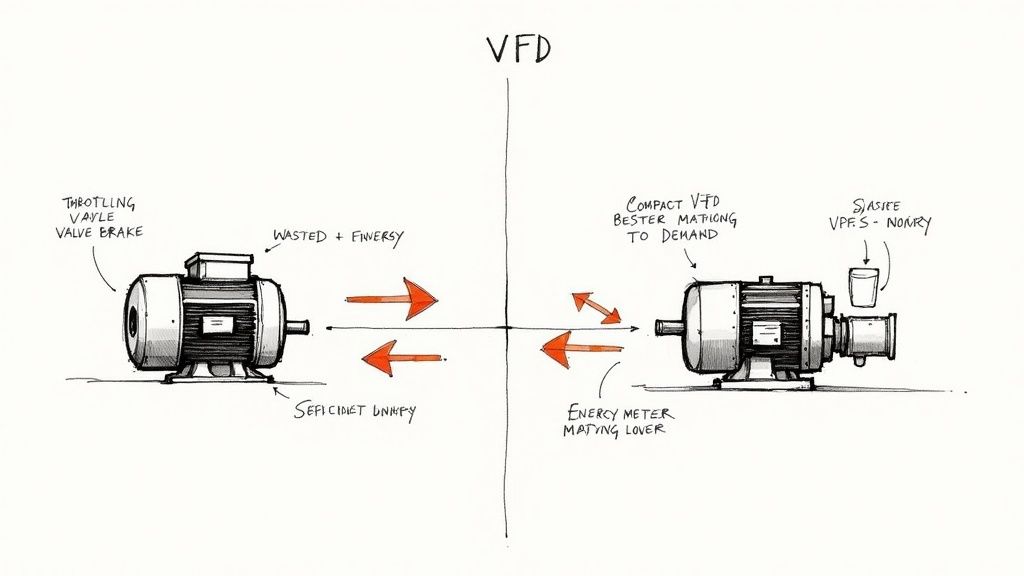
VFD Control vs Traditional Mechanical Control
To really see the difference, it helps to compare the two approaches side-by-side. The old method is about brute force, while the VFD approach is about intelligence and finesse.
Attribute
VFD Control
Throttling or Damper Control
Energy Efficiency
High; motor speed matches load, minimizing waste.
Extremely low; motor runs at full speed, excess energy is lost.
Control Precision
Excellent; allows for precise and dynamic speed adjustments.
Poor; offers crude, step-based control with high-pressure drops.
Mechanical Stress
Low; soft starting and stopping reduces wear and tear.
High; abrupt starts and stops cause significant mechanical shock.
System Flexibility
High; easily adapts to changing process demands.
Low; fixed-speed operation is rigid and inefficient.
Maintenance
Reduced; less stress on components leads to longer life.
Increased; higher stress accelerates wear on valves, bearings, and motors.
The table makes it clear: VFDs aren't just an upgrade; they represent a smarter, more sustainable way to manage motor-driven systems.
If you're just getting started, it helps to get a handle on the key components and how they work together. Our in-depth guide on Variable Frequency Drive basics is the perfect place to build that foundation.
How VFDs Turn Speed Reduction Into Big Savings
To really get why VFDs can slash energy bills, we have to look past the hardware and talk about a core principle in physics: the Affinity Laws. These laws are the playbook for how centrifugal equipment—think pumps and fans—operates. And they reveal a frankly stunning relationship between a motor's speed and how much power it guzzles.
You'd think that if you slow down a fan by 20%, you’d use 20% less energy, right? It seems logical, but that's not how it works. The relationship isn't a straight line; it's exponential, and that’s where the magic happens.
The Power of the Cube
The Affinity Laws lay it out clearly: the power a motor needs is directly proportional to the cube of its speed. This is the secret sauce behind the incredible savings a VFD delivers. A small tweak to the speed has an enormous impact on your power consumption.
Power ∝ (Speed)³. This is the key. That cubic relationship means even a modest drop in motor speed leads to a massive plunge in energy use. It's the whole reason VFDs are so effective for fans, pumps, and other variable torque applications.
This principle is what makes VFDs such a no-brainer. Instead of brute-forcing a system with mechanical dampers or throttling valves—which is like driving your car with one foot on the gas and the other on the brake—a VFD simply tells the motor to do less work. It's elegant and incredibly efficient.
A Real-World Ventilation Fan Example
Let’s put some real numbers on this. Picture a large ventilation fan in a factory. It’s designed to run full tilt, but for most of the day, the building only needs about 80% of its maximum airflow.
Without a VFD: The motor screams along at 100% speed, all day, every day. To cut the airflow, a mechanical damper closes, physically blocking 20% of the air. The motor is still working its heart out, fighting against that restriction, and all that wasted energy just turns into heat and noise.
With a VFD: Forget the damper. The VFD just slows the motor down to 80% of its full speed. Simple.
Now, let's plug that into the Affinity Law and see what happens to the power draw.
Speed Reduction:80% (or 0.8) of full speed.
Power Calculation: (0.8)³ = 0.8 x 0.8 x 0.8 = 0.512
By trimming the fan speed by just 20%, the VFD cuts the energy consumption all the way down to 51.2% of the original amount. That’s a jaw-dropping 48.8% reduction in power from a small change in output. This is exactly the kind of VFD energy savings that can completely change a facility's operating budget. If you want to dig deeper into the mechanics, our detailed article on https://eandisales.com/business/ac-motor-variable-speed/ is a great place to start.
Applications Beyond Industrial Fans
This powerful concept of matching speed to real-time demand isn't just for huge industrial machines. You see the same principle at play in all sorts of applications. For example, modern variable speed heat pumps use it to deliver huge comfort and efficiency gains in our homes.
The core idea is universal. Whenever demand isn't constant, adjusting speed is always smarter than running at full blast and choking the output. Whether it’s a massive water pump or a residential air conditioner, variable speed technology is the key. This is why understanding the Affinity Laws is so important—it takes the promise of VFDs from an abstract idea to concrete, bankable savings.
Calculating Your VFD Savings and Payback Period
Knowing the theory is one thing, but making a rock-solid business case requires real numbers. This is where we bridge the gap between the Affinity Laws and your facility's bottom line. By nailing down your potential VFD energy savings and the payback period, you can walk into any budget meeting with confidence.
The process isn't as complicated as it might sound. It's really just a "before and after" comparison. We'll figure out what a specific motor is costing you right now, then project the new, lower costs once a VFD is doing the work.
Let's run through a practical, real-world scenario to see exactly how the numbers shake out.
Step 1: Establish Your Baseline Energy Cost
First things first: you need to know your starting point. To do that, you’ll need to grab a few key pieces of data for the motor you’re looking to upgrade.
Motor Horsepower (HP): The rated power stamped right on the motor.
Operating Hours: How many hours per year that motor is actually running.
Electricity Rate: Your cost per kilowatt-hour (kWh), which you can find on your utility bill.
Motor Efficiency: The rated efficiency of your current motor, also usually on the nameplate.
To get the most accurate numbers, you have to track your energy use properly. Grabbing a good power consumption monitor is a smart move. It gives you the precise data you need for these initial calculations and for proving the savings later on.
A Worked Example: 100 HP Pump Motor
Let's put this into practice with a very common piece of equipment: a 100 HP pump motor that runs for 6,000 hours per year.
Here are our assumptions:
Motor HP: 100 HP
Conversion Factor: 0.746 kW per HP
Motor Efficiency: 94% (a standard for a premium efficiency motor)
Operating Hours: 6,000 hours/year
Electricity Rate: $0.12 per kWh
First, we calculate the power consumption in kilowatts (kW) when it's running flat out: Power (kW) = (100 HP * 0.746 kW/HP) / 0.94 efficiency = 79.36 kW
Next, let's figure out the total annual energy consumption in kWh: Annual kWh = 79.36 kW * 6,000 hours = 476,160 kWh
And finally, the total annual electricity cost without a VFD: Annual Cost (No VFD) = 476,160 kWh * $0.12/kWh = $57,139
That's right—running this single pump at full speed costs over $57,000 a year. That’s our baseline.
Step 2: Calculate Your VFD Energy Savings
Now, let's see what happens when we install a VFD. Let’s say that for half its run time (3,000 hours), the process only needs the pump to run at 70% speed. For the other 3,000 hours, it still needs to go full throttle.
This is where the magic of the Affinity Laws really kicks in.
As you can see, a small drop in speed creates a massive drop in power consumption. It's not a 1-to-1 relationship; it's a cubic one, which is what makes VFDs so powerful.
Let’s calculate the power draw at 70% speed using that cubed relationship (Power ∝ Speed³): Power at 70% Speed = 79.36 kW * (0.7)³ = 79.36 kW * 0.343 = 27.22 kW
Now we can calculate the new annual energy usage with the VFD in control:
New Total Annual kWh: 238,080 + 81,660 = 319,740 kWh
And the new annual cost: Annual Cost (With VFD) = 319,740 kWh * $0.12/kWh = $38,369
The savings are immediate and substantial: Total Annual Savings = $57,139 – $38,369 = $18,770
That's a 33% reduction in annual energy costs, just from matching the motor's speed to what the process actually needs. If you want to dive deeper into how different factors play into this, check out our resources on https://eandisales.com/tag/motor-efficiency/.
Step 3: Determine the Payback Period
The last step is the one everyone wants to see: how fast does this investment pay for itself? The simple payback period is just the total project cost divided by the annual savings.
Let's say the all-in installed cost for the VFD is $25,000. This covers the drive itself, any necessary filters, and professional installation.
Payback Period (Years) = Total Project Cost / Annual Energy Savings Payback Period = $25,000 / $18,770 = 1.33 years
A payback of just over 16 months makes this an incredibly compelling project. For some operations, it’s even faster. One ceramics factory in Poland, for instance, modernized its systems with VFDs and saw a payback in just seven months after achieving a 30% reduction in energy use. These kinds of results are becoming more and more common.
Common Mistakes That Undermine VFD Savings
Slapping a VFD on a motor isn't a silver bullet for your energy bills. While the potential for savings is huge, a few common and costly mistakes can chew right through your expected ROI, sometimes wiping it out completely. Getting real VFD energy savings means thinking about the drive as one part of a much bigger system.
Time and again, we see facilities make the same handful of errors, turning a promising efficiency project into just another frustrating expense. If you know what these pitfalls are ahead of time, you can steer clear and make sure your VFD project actually delivers the numbers you planned for. Let's walk through the four biggest mistakes we see out in the field.
Oversizing the Drive and Motor
It's a classic engineering impulse: build in a safety margin. But when it comes to VFDs and motors, "bigger" is almost never better. An oversized VFD—one rated for way more horsepower than the motor actually needs—ends up operating in a highly inefficient part of its performance curve. It wastes energy before it even gets to the motor.
It's the same story with an oversized motor. Forcing it to consistently run at less than 40% of its full rated load makes it incredibly inefficient. This habit doesn't just inflate your initial purchase price; it locks in an energy penalty that you'll pay for the entire life of the equipment.
The real secret is to size the VFD and motor for the actual work being done, not some theoretical maximum load that might happen once in a blue moon. Doing accurate load profiling before you buy anything is the single best way to dodge this expensive mistake.
Implementing a Poor Control Strategy
A VFD is only as smart as the instructions it gets. One of the most common ways we see savings evaporate is through a sloppy control strategy. This can show up in a few different ways, but each one chips away at your potential savings.
Running in "Hand" Mode: You'd be surprised how often a technician leaves a VFD in manual (or "Hand") mode, forcing it to run at a fixed speed. Often, that speed is 100%. This effectively turns your sophisticated VFD into a dumb motor starter, killing any chance of saving energy.
Incorrect Setpoints: If you set a pressure or flow setpoint higher than the system actually requires, you're forcing the VFD to run the motor faster than needed, 24/7. It's a constant, silent energy drain.
Forgetting About the Bypass: Most VFDs have a bypass contactor to run the motor across the line if the drive fails. If that bypass gets left on by mistake, all your potential savings are gone. The VFD is just an expensive box on the wall.
Proper commissioning from the start and regular check-ins are essential. You have to make sure the control logic is still optimized for savings and hasn't been overridden for convenience.
Ignoring the Broader System Context
A VFD can't fix a fundamentally flawed system. It’s a tool that optimizes a motor's performance within the existing mechanical setup. If that setup is inefficient, the VFD's impact will be severely limited.
Think of it like dropping a high-performance engine into a car with flat tires and a clogged exhaust. The engine has plenty of power, but the rest of the car is holding it back.
Here are some common system-level problems that hamstring VFDs:
High static head in pump systems: If a pump has to fight gravity just to lift water to a certain height, it has a high static head. This creates a hard floor on how much you can slow the pump down, which puts a ceiling on your potential savings.
Inefficient ductwork or piping: Clogged filters, undersized pipes, and poorly designed ductwork create a ton of resistance. This forces the motor to work harder than it should. A VFD can help, but you'll save far more if you fix these mechanical issues first.
You have to look at the whole picture. Before you even think about a VFD, analyze the entire mechanical loop to find and fix the blockages that will kill your savings potential.
Overlooking Power Quality Issues
Finally, don't forget that a VFD is a complex piece of electronics that has a real impact on your facility's electrical network. By their very nature, VFDs create harmonic distortion as a byproduct of how they work. Without the right mitigation, these harmonics can cause serious problems that erode your efficiency and reliability.
Harmonics can lead to transformers and wiring overheating, circuit breakers tripping for no apparent reason, and interference with other sensitive electronic gear. Every one of these issues introduces waste and eats into the VFD energy savings you were counting on.
Installing the right line reactors or harmonic filters isn't an optional add-on. It's a non-negotiable step to protect both your VFD investment and the health of your entire electrical system.
Getting Your VFD Installation and Verification Right
Realizing the full VFD energy savings you've been promised takes more than just bolting a drive to the wall. It’s all about a smart approach—thoughtful planning, a clean installation, and actually proving the results. Let’s walk through the playbook that separates a successful VFD project from a disappointing one.
The first, and most important, step happens before you ever order a drive. You have to get intimate with the application. Is it a fan or a pump? What’s the real-world operating load profile look like—not just the motor's nameplate rating? Answering these questions first confirms a VFD is even the right tool for the job and helps you size it for peak efficiency.
Smart Installation Strategies
Once you’ve got the green light, the focus shifts to a safe, reliable installation. This isn't the place to cut corners. Rushing the install is a fast track to performance headaches, safety risks, and equipment that dies an early death.
A hugely effective strategy is to opt for pre-engineered, UL-listed control panels. These aren't just boxes; they're integrated systems. The VFD, circuit protection, controls, and any necessary filters are all packaged together in a single, tested enclosure. This move ensures you're up to code, but just as importantly, it makes the field installation faster and drastically cuts down on the chance of wiring mistakes.
Don’t forget about harmonic mitigation. It’s easy to overlook, but VFDs naturally create electrical "noise" (harmonics) that can wreak havoc on other sensitive equipment on your network. Installing the right line reactors or harmonic filters isn't an optional upgrade. It's a non-negotiable part of a professional install that protects your entire facility.
The Make-or-Break Role of Commissioning
This is where the magic happens. Proper commissioning is the process that turns theoretical savings into actual dollars. It involves a skilled technician dialing in the VFD’s parameters to perfectly match what your system needs. They’ll tweak things like acceleration/deceleration ramps, set proper speed limits, and fine-tune PID loop controls so the motor runs as lean as possible.
This is absolutely not a "set it and forget it" task. Commissioning is about making sure your control strategy perfectly mirrors your system’s real demands. It prevents common energy-wasters like running at a setpoint that’s too high or having the motor constantly "hunt" for the right speed. Skipping this is like buying a race car and never taking it out of first gear.
Prove Your Savings: Measurement and Verification
So, how do you actually know if the VFD is saving you money? You prove it. That’s what Measurement and Verification (M&V) is all about—tracking performance to put a hard number on your savings. This step is critical for calculating your ROI and making the case for the next efficiency project.
You can tackle M&V in a few ways:
Onboard VFD Data: Most modern drives are smart enough to log key data like kWh consumed, run hours, and operating speeds. It’s a simple, built-in way to keep tabs on energy use.
External Power Meters: For rock-solid, undeniable proof, installing a dedicated kilowatt-hour meter on the VFD’s input is the gold standard. The numbers don't lie.
Baseline Comparison: The whole point of M&V is to compare the "after" with the "before." By putting your new energy numbers up against the baseline data you gathered pre-VFD, the reduction in consumption becomes crystal clear.
This isn't just theory. A project in the mining sector found that swapping to VFD-controlled pumps slashed their energy costs by nearly 20%. That added up to over $3 million in cumulative savings in 15 years. This is the power of verifying your results—it confirms the financial win and the benefit of longer equipment life. You can dig into the case study on these VFD savings in mining operations.
Answering Your Top Questions About VFDs
When you start digging into VFDs for your facility, a lot of practical questions pop up. It’s only natural. Here, we'll tackle the most common ones we hear from plant managers and engineers in the field, using what we've already covered to give you straight, clear answers. The goal is to help you feel confident about the decisions you’re making to unlock real energy savings.
Will a VFD Save Energy on Any Motor?
This is a fantastic question, and the short answer is no—at least, not in the same way. The real savings potential from a VFD comes down to what kind of work the motor is doing.
VFDs shine brightest when they're paired with "variable torque" loads. Think of your centrifugal pumps and fans. These machines are a perfect match for the Affinity Laws we talked about earlier, where a small drop in speed leads to a massive drop in energy consumption. This is the VFD sweet spot, where cutting energy use by 30% to 50% is a totally realistic goal.
Then you have your "constant torque" loads. This includes equipment like conveyors, positive displacement pumps, or industrial mixers. The savings here are much more straightforward and directly proportional to the speed reduction. If you slow a conveyor down by 20%, you’ll save roughly 20% on energy. Those savings are definitely worth having, but you won't see the same exponential impact you get with fans and pumps.
The Bottom Line: Before you do anything else, identify your load type. Knowing if you have a variable or constant torque application is the single most important factor in figuring out if a VFD project will pay off.
So, How Much Energy Can I Actually Save?
The honest-to-goodness answer? It all comes down to your application's load profile. A VFD only saves you money when your process allows it to slow the motor down. The more time that motor spends running below full speed, the more cash you'll see back in your operating budget.
Let's imagine two scenarios with the exact same fan motor:
The High-Variation System: A building's ventilation system runs at 60% speed for 12 hours overnight and then ramps up to 100% for 12 hours during the day. This setup is going to see huge savings because it's leaning heavily on those Affinity Laws for half its life.
The Low-Variation System: A process fan has to run at 95% speed nearly all day, only kicking up to 100% every so often. A VFD will still give you great control, but the energy savings will be pretty slim because the speed reduction is just too small.
The key isn't just bolting on a drive; it's understanding how much your process really needs to vary. A good, hard look at your system's demand cycle is the only way to get a realistic savings forecast.
Doesn't the VFD Itself Use Power?
It sure does. A VFD is a complex piece of power electronics, and just like any other electronic device, it has some minor efficiency losses. It's constantly converting AC power to DC, then chopping it back up into a simulated AC waveform to control the motor.
A modern, high-quality VFD is typically about 97-98% efficient. That means it consumes a small slice—around 2-3%—of the power that passes through it.
But here’s the crucial part: that tiny internal loss is a drop in the bucket compared to the massive system-level savings the VFD makes possible. For any well-chosen variable torque application, the energy you save by slowing the motor down will absolutely dwarf the small amount the drive itself uses. The net result is always a big win for your energy bill.
What Are the "Hidden Costs" of a VFD Project?
Budgeting for a VFD means looking past the sticker price of the drive itself. A handful of other components and services are almost always needed to get the job done right and ensure the system is reliable for the long haul. Getting these on your radar from the start gives you a much more accurate picture of the total project cost.
Here are the usual suspects to account for:
Professional Installation: A VFD isn't a toaster you just plug in. It needs proper wiring, grounding, and controls integration by a qualified electrician who knows what they're doing.
Shielded Motor Cable: To keep the VFD from creating electrical "noise" (EMI/RFI) that can mess with other sensitive equipment in your plant, you'll often need special shielded cable running from the drive to the motor.
Harmonic Mitigation: As we've covered, VFDs can pollute your electrical system with harmonics. Depending on the existing power quality in your facility, you might need to add a line reactor or a harmonic filter to keep everything running smoothly.
Commissioning & Programming: This is a big one. A qualified technician needs to program the drive's parameters to perfectly match your motor and application. This step is what truly optimizes performance and makes sure you hit your VFD energy savings targets.
Bypass Contactors: For critical processes that can't ever go down, a bypass is often installed. This lets you run the motor directly off the line if the VFD ever fails, guaranteeing uptime.
Factoring in these items ensures your project isn't just up and running, but that it's also safe, reliable, and built to last.
At E & I Sales, we don’t just sell VFDs out of a box. We engineer complete solutions inside UL-listed control panels, designed and built to make your project a success from day one. If you're ready to stop talking about savings and start seeing them, let's have a conversation.