Three-phase monitoring is like a continuous health check for your most critical industrial equipment. It’s all about spotting electrical issues like voltage imbalances or current spikes before they can cause a catastrophic failure, giving you the hard data needed to prevent costly downtime and protect high-value assets.
What Is Three Phase Monitoring and Why It Matters
Think about a three-person crew perfectly synchronized, lifting a heavy, expensive piece of machinery. When all three lift with equal force and timing, the load is stable and everything goes smoothly. But what happens if one person stumbles or suddenly loses their grip? The whole operation is at risk. The load becomes unstable, putting immense strain on the other two and risking a disastrous drop.
That’s the perfect way to think about three-phase power. The big motors and pumps that drive your operations depend on three balanced electrical currents—or "phases"—to run efficiently and safely. When those phases are in harmony, your equipment runs like a dream.
The High Cost of an Imbalance
The trouble starts when one phase weakens, surges, or disappears entirely. This condition, known as phase loss or imbalance, has severe and immediate consequences. Your motor is suddenly forced to work much harder under incredible stress, causing it to overheat in a hurry. This kind of thermal stress degrades insulation and can completely destroy windings, leading to a premature and catastrophic failure.
This is why proper three-phase monitoring is so vital for maintaining the health of complex electrical systems. It’s designed to identify these subtle problems long before they escalate into serious equipment damage, acting as an early warning system that gives your team the data they need to step in and fix things.
An unbalanced electrical supply is one of the biggest culprits behind motor failure. Even a small voltage imbalance can dramatically spike a motor's temperature and literally cut its operational lifespan in half, turning a preventable issue into a major capital expense.
Turning Data into Reliability
The real goal of three phase monitoring isn't just about collecting a bunch of data points; it's about turning that data into rock-solid reliability. By keeping a constant watch on the vital signs of your power supply, you can:
Prevent Unplanned Downtime: Catch phase imbalances, voltage sags, and overcurrent conditions before they trip breakers or burn out motors.
Extend Equipment Lifespan: Make sure your motors run well within their specified limits, which drastically reduces wear and tear from electrical stress.
Improve Energy Efficiency: Pinpoint and fix power quality issues that cause equipment to draw more power than needed, helping to lower your operational costs.
In the world of industrial power management, three-phase multifunction monitoring relays are a cornerstone technology. To give you an idea of their importance, the global market for these relays was $1,120.68 million back in 2021 and is projected to climb to $1,438.9 million by 2025. That growth tells you everything you need to know about their vital role in protecting critical assets.
Understanding Your System's Electrical Vitals
To really get a handle on protecting your motors, you need to speak their language. The data from your monitoring system isn't just a bunch of numbers—it's the vital signs of your entire electrical operation. We're going to move past the textbook definitions and get into why each of these metrics is a make-or-break indicator for performance and reliability.
It helps to think of your electrical system like the plumbing in a huge building. The parallels are surprisingly useful and can make some pretty complex electrical ideas click into place. Suddenly, those abstract figures on a screen become real, actionable intelligence.
The Core Duo: Voltage and Current
Let's start with the absolute basics: voltage and current. These two are the foundation of everything else.
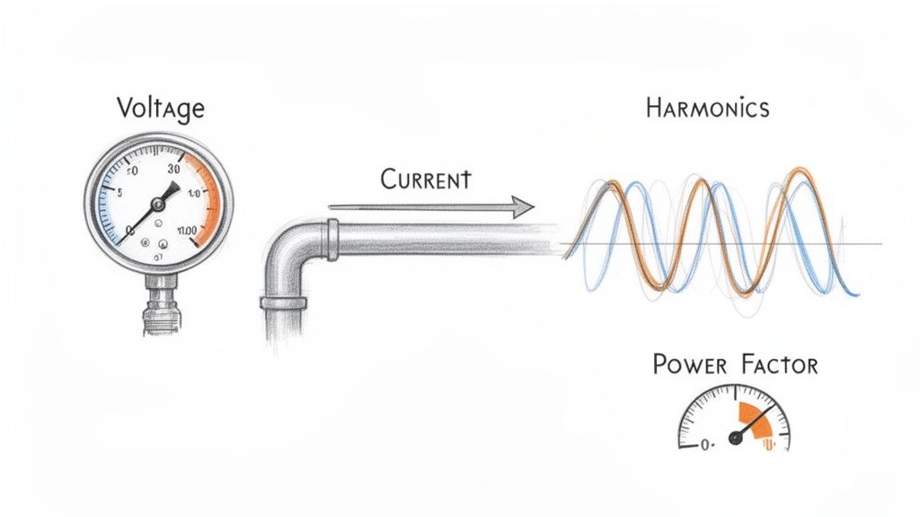
Voltage is your electrical 'pressure.' Just like water pressure is needed to push water through pipes, voltage is the force pushing electrical energy through the wires to your equipment. If that pressure drops too low (undervoltage), your motor will strain to do its job, causing it to overheat and run inefficiently. On the flip side, if the pressure is too high (overvoltage), you risk frying sensitive components and drastically shortening the motor's life.
Current is the 'flow rate.' Measured in amps, it's the amount of electricity your motor is actually pulling to get the work done. A sudden, sharp spike in current is often the first red flag that a motor is struggling with a mechanical problem, like a bearing starting to seize up or a jam on the conveyor line. Watching the current gives you a live look at the motor's real-world workload.
Keeping a close eye on voltage and current is ground zero for any effective three-phase monitoring plan. These two numbers are the starting point for diagnosing nearly every other electrical headache you might encounter on the factory floor.
Imbalance: The Uneven Workload
This is where the 'three' in three-phase power becomes so important. An imbalance happens when the voltage or current isn't perfectly equal across all three phases. Think of it like a three-person team trying to lift something heavy, but one person is slacking off. The other two have to work way harder to pick up the slack, putting a dangerous amount of strain on them.
For a motor, that uneven load is a death sentence. The imbalance creates what are called negative sequence currents, which actively work against the motor's rotation. This generates a massive amount of waste heat, and that thermal stress is one of the biggest killers of winding insulation, leading directly to costly and premature motor burnouts. A solid grasp of motor control circuit design is crucial for understanding how these imbalances wreak havoc.
Harmonics: The Electrical Pollution
Harmonics are a type of electrical 'pollution,' and a common culprit is modern equipment like Variable Frequency Drives (VFDs). VFDs are fantastic for controlling motor speed and saving energy, but they don't draw power in a nice, smooth sine wave. Instead, they chop it up, creating distortion and 'noise' that gets reflected back into your entire electrical system.
This harmonic distortion is especially brutal on motors and transformers, causing them to vibrate and overheat. It's like feeding your equipment electrical junk food; it'll run, but it’s causing serious long-term damage. This is a huge issue in modern plants, where it's not uncommon for 70% of motor drives to be affected by VFD-induced harmonics, making advanced power quality meters an absolute must-have. You can dive deeper into how to improve your overall electrical power quality.
The numbers don't lie. The market for the very three-phase power quality meters needed to fight these issues was on track to hit $1,252 million back in 2021. This explosive growth is a direct answer to the staggering cost of outages, which hit manufacturers for an estimated $50 billion every year.
Power Factor: Your Efficiency Score
Finally, we have the power factor. This metric, scored on a scale from 0 to 1, is basically your system's efficiency report card. It tells you how effectively your equipment is turning the electricity it receives into actual, useful work.
A low power factor (say, 0.75) means your system is pulling more current from the grid than it's actually using, which is just wasted energy. This not only bloats your utility bills but also puts unnecessary stress on your transformers and wiring. In fact, many utility providers will hit you with hefty penalties for a poor power factor, making it a critical number to watch for financial reasons alone. Consistent three phase monitoring is the only way to keep this vital sign healthy.
To tie this all together, here's a quick-reference table breaking down these critical parameters. Think of it as a cheat sheet for diagnosing the health of your three-phase systems at a glance.
Critical Three Phase Monitoring Parameters and Their Impact
Parameter
What It Measures
Sign of a Problem
Risk of Inaction
Voltage
Electrical 'pressure' in the system.
Sustained levels outside the +/- 10% nominal range (sags or swells).
Equipment damage, overheating, premature failure.
Current
Electrical 'flow rate' consumed by the load.
Sudden, unexplained spikes or consistently high readings.
Overheating, insulation breakdown, imminent motor failure.
Imbalance
The difference in voltage or current between phases.
A deviation of more than 1-2% between any two phases.
Severe motor overheating, drastically reduced lifespan, burnout.
Harmonics
Distortion or 'pollution' on the electrical waveform.
High Total Harmonic Distortion (THD), especially from VFDs.
Overheating of motors/transformers, equipment malfunction.
Power Factor
Efficiency of converting power to useful work.
A value consistently below 0.90.
High energy bills, utility penalties, wasted system capacity.
Understanding what these numbers mean is the first step. By actively monitoring them, you're not just collecting data—you're getting ahead of catastrophic failures, optimizing energy use, and protecting your most valuable assets.
The Hardware You Need for Accurate Monitoring
Knowing what to measure is one thing, but having the right tools for the job is what makes effective three-phase monitoring actually happen. Think of your monitoring system as a small, specialized team. You’ve got the sensors acting as the eyes and ears, the meter as the brain crunching the numbers, and the protective gear that steps in when things get dicey.
Putting this team together correctly is the difference between getting raw data and getting real, actionable intelligence. It's how you spot trouble brewing long before it takes down a critical piece of equipment.
The Eyes and Ears of Your System
First things first: you can't just hook up a multimeter to a 480V industrial circuit. It’s not just impractical; it’s incredibly dangerous. That's where instrument transformers come in. They are the essential sensory organs of your entire setup.
There are two main types you'll be working with:
Current Transformers (CTs): These are your system's 'ears.' A CT is a ring you simply clamp around one of the main power conductors. It doesn't make any direct electrical contact. Instead, it senses the magnetic field generated by the current and scales it down to a safe, low-level signal that a meter can easily read.
Potential Transformers (PTs): These are the 'eyes.' A PT (or voltage transformer) is wired in parallel with the high-voltage line. It does for voltage what a CT does for current—stepping it down from something like 480V to a standardized, safe level like 120V for your meter to analyze.
These two components work in tandem to provide a safe, perfectly scaled-down version of the heavy-duty power flowing through your circuits, feeding reliable information to the brain of the operation.
The Brain of the Operation: Power Meters
All that data from the CTs and PTs is just noise without something to make sense of it. That’s the job of the multifunction power meter—the true brain of any modern monitoring system. These aren't just simple readouts; they're powerful little computers that take the raw signals and instantly calculate everything we care about, from basic voltage and current to tricky stuff like power factor and harmonic distortion.
The market for these devices is exploding, projected to hit $15 billion by 2025, which shows just how critical they've become. In industrial motor control centers, where a simple imbalance can be responsible for 25% of all motor failures, these smart meters are non-negotiable. You can dig into the numbers yourself by reading the full market research on this industrial shift.
A multifunction meter is the nerve center of your monitoring strategy. It translates the complex electrical language of your system into clear, understandable metrics you can actually use to make smart decisions.
Protective Relays and Analyzers
If the meter is the brain, then a protective relay is the system's guardian angel. This device goes a step beyond just monitoring—it takes action. You can program a relay to automatically trip a breaker if it sees a dangerous condition, like a massive overcurrent or a complete phase loss. It’s an automated safety net that can shut down a motor before it self-destructs, reacting far faster than any human ever could.
For those really tricky, intermittent electrical gremlins, you might need to bring in the specialist: a power quality analyzer. While your meter gives you the day-to-day vital signs, an analyzer is like an EKG for your electrical system. It can capture high-speed events and perform a deep-dive analysis of harmonic issues, helping you find the root cause of problems that otherwise seem to appear and disappear at random. Whether you need a standard meter or a full-blown analyzer really just depends on how complex your facility is and how deep you need to go.
Integrating Monitoring into Your Control Panels
Having the right hardware is a great start, but a pile of even the best components doesn't automatically create an intelligent system. The real magic happens when you bring it all together. Integration is where you transform individual devices into a single, cohesive network that gives you clear, actionable data.
Think of it as building the central nervous system for your electrical assets, connecting them all back to your main command center.
This process is about more than just plugging things in. It demands careful planning to ensure everything is safe, the signals are clean, and you’re compliant with standards like the National Electrical Code (NEC). When you get it right, data flows seamlessly from your current transformers and meters directly into your PLC or SCADA system, painting a live picture of your entire operation's electrical health on one central dashboard.
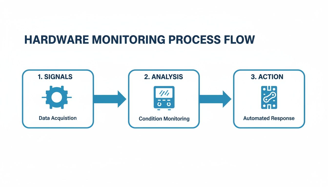
This flowchart shows the fundamental journey of data in a three-phase monitoring system—from a raw signal to an intelligent action.
As you can see, it starts with sensors gathering the raw electrical data. That data is then processed by a meter and finally used to trigger a protective or automated response.
Wiring Best Practices for Signal Integrity
Reliable data starts with clean wiring. Industrial environments are electrically noisy places, full of interference from large motors and VFDs. Protecting the low-voltage signals coming from your monitoring hardware is absolutely critical. A corrupted signal can lead to false alarms or, far worse, a missed fault condition that could have been prevented.
To keep your signals clean, stick to these essential best practices:
Use Shielded Cabling: Always run shielded twisted-pair cables for your communication lines (like Modbus or Ethernet) and for the analog signals from CTs and PTs. This shield is your first line of defense against electromagnetic interference (EMI).
Proper Grounding: Ground the shield at one end only, usually at the control panel or meter side. If you ground both ends, you can create a ground loop, which actually invites noise onto the line and corrupts the very signal you're trying to protect.
Separate Power and Signal Wires: This is a big one. Never run your low-voltage signal wiring in the same conduit or wire tray as high-voltage power cables. Keep them as far apart as possible to prevent the powerful magnetic fields from the power lines from bleeding noise into your sensor wiring.
Connecting to Your PLC and SCADA Systems
Once your hardware is properly wired, the next step is talking to your primary control system, whether that's a Programmable Logic Controller (PLC) or a Supervisory Control and Data Acquisition (SCADA) system. This is what unlocks centralized three phase monitoring and historical data logging.
Most modern meters speak the common industrial languages. The ones you’ll run into most often are:
Modbus RTU: A serial communication protocol that's been the workhorse of industrial automation for decades. It's incredibly reliable and supported by pretty much every PLC and HMI out there.
Modbus TCP/IP: This is the Ethernet version of Modbus, letting your meters connect directly to the facility's network. It’s faster and gives you more flexibility for tying into modern SCADA systems.
EtherNet/IP: Another popular Ethernet-based protocol, especially common in plants that lean heavily on Rockwell Automation/Allen-Bradley PLCs.
The goal here is to map the data registers from the meter to the tags in your PLC or SCADA software. This mapping tells the control system where to look for specific data points—like the voltage on Phase A, the total harmonic distortion, or the power factor—so it can be displayed, logged, and used to trigger alarms.
Proper integration isn't just about seeing what's happening right now; it's about creating a historical record. That data lets you track trends over time, figure out what really happened after a trip, and finally shift from reactive repairs to a data-driven, predictive maintenance strategy.
The Role of UL-Listed Control Panels
While you could piece together a monitoring system yourself, that path is loaded with risks related to safety, compliance, and performance. This is where professionally engineered, UL-listed control panels are worth their weight in gold.
A UL listing (like UL508A for industrial control panels) is an independent stamp of approval certifying that the entire panel assembly—not just the individual parts—meets tough safety and construction standards. To really appreciate the work that goes into this, it's worth exploring the principles behind industrial control panel design.
Going with an expertly engineered and certified panel takes the guesswork and risk out of the equation. It guarantees that all components were chosen to work together perfectly, wired according to best practices, and fully tested before they ever show up at your facility. This approach saves a massive amount of time during commissioning and ensures you get reliable, safe performance from day one.
Translating Monitoring Data into Actionable Fixes
All that raw data streaming from your meters? It's just noise until you know how to read it. The real power of three phase monitoring isn't in collecting data—it's in translating those numbers into smart, decisive action.
Think of this as your field guide for turning a blinking light on a screen into a practical fix on the floor. When you understand the story the data is telling, your team can stop reacting to problems and start preventing them, catching small electrical issues before they have a chance to snowball into catastrophic failures.
Diagnosing a Persistent Voltage Imbalance
A voltage imbalance alert is one of the most common—and destructive—issues you'll run into. If your system flags a persistent difference of more than 1-2% between phases, that’s a direct warning that your motors are under serious thermal stress.
First things first, you have to find where the problem is coming from. Voltage imbalances usually have one of two sources: an issue inside your facility or a problem with the power coming from the utility.
Here’s how to track it down:
Isolate the Source: Start at your main service entrance. Check the voltage before it gets to your distribution panels. If the imbalance is already there, the problem is likely on the utility’s end. Time to give them a call.
Inspect Your Panels: If the power coming in is clean and balanced, the issue is on your side of the meter. The usual suspect? Too many single-phase loads—things like office equipment, lighting, or small heaters—loaded up on one or two phases.
Balance the Loads: This is a job for an electrician. They can help redistribute those single-phase circuits more evenly across your panels. The goal is to get the current draw on each phase as close to equal as possible, which will bring your voltage back into balance and save your three-phase gear.
Responding to Overcurrent and Overload Alerts
An overcurrent alert means a piece of equipment, usually a motor, is pulling more current than its nameplate rating. This is a critical warning. Sustained overcurrent is the number one cause of motor overheating and burnout. The root cause could be mechanical or electrical.
Start by looking at the nature of the overcurrent. Was it a massive, sudden spike, or has it been creeping up over time?
A sudden trip often points to a mechanical jam, a short circuit, or a ground fault. A slowly rising current, however, typically indicates a developing mechanical issue, like a failing bearing that is forcing the motor to work progressively harder.
This distinction is key. If the current spike was instantaneous, you should be inspecting the driven equipment for a physical jam. If the current has been climbing for a while, the motor itself is the likely culprit and needs a mechanical inspection. This is the kind of insight that builds an effective strategy for predictive maintenance for manufacturing operations.
Tackling Low Power Factor and Harmonics
Alarms for low power factor and high harmonic distortion often go hand-in-hand. A poor power factor (anything below 0.90 is a red flag) means you're wasting energy and probably getting hit with utility penalties. High Total Harmonic Distortion (THD), often created by VFDs, pollutes your electrical system and causes sensitive equipment to overheat.
When these alarms pop up, the fix usually involves power quality correction.
For Low Power Factor: The most direct fix is to install power factor correction capacitors. Think of them as a local reservoir of reactive power, improving efficiency and reducing the current your facility has to draw from the grid.
For High Harmonics: If VFDs are creating the electrical noise, installing harmonic filters or line reactors is the solution. These components act like shock absorbers, cleaning up the distortion and protecting everything else on the circuit.
By connecting specific alerts to a logical diagnostic process, your team can act quickly and with confidence. This table is a quick cheat sheet for that initial response.
Measure voltage at the main service entrance to isolate the source.
Overcurrent Trip
Mechanical jam, bearing failure, short circuit.
Check driven equipment for obstructions; analyze current trend data.
Low Power Factor
Inductive loads (motors) without correction.
Install power factor correction capacitors at the motor or panel.
High Harmonics
Prevalent use of Variable Frequency Drives (VFDs).
Install harmonic filters or line reactors to absorb distortion.
Having a simple, repeatable process takes the guesswork out of troubleshooting and turns your monitoring system into a true problem-solving tool.
The Financial Case for Three-Phase Monitoring
While the technical perks of three-phase monitoring are obvious to any engineer, the decision to actually write the check often boils down to one simple question: what’s the payback?
A well-planned monitoring strategy isn’t just another line item in the maintenance budget. It's a powerful financial tool that pays for itself, often many times over, by preventing catastrophic costs and finding hidden efficiencies you never knew you had.
The numbers are staggering. Unscheduled downtime in manufacturing costs the industry an estimated $50 billion every year. A huge chunk of that comes from electrical issues that a good monitoring system is built to see coming a mile away. Let's get out of the clouds and look at a couple of real-world situations where this tech delivers a direct, measurable ROI.
From Unplanned Downtime to Scheduled Maintenance
Picture a big manufacturing plant where a single critical conveyor motor is the heart of the main production line. Without monitoring, the first sign of a problem is usually the motor seizing up, bringing everything to a screeching halt.
This kind of surprise shutdown unleashes a torrent of costs: lost revenue for every minute the line is down, overtime for the scramble to fix it, and maybe even rush shipping for a new motor. A single incident like this can easily balloon into tens or even hundreds of thousands of dollars.
Now, let's hit rewind and play that same scenario back, but this time with a solid three-phase monitoring system installed.
The Problem: The system starts picking up on a small but steady climb in the motor's current draw over a few weeks, along with a slight phase imbalance.
The Monitoring Solution: This data automatically triggers an alert for the maintenance manager. The pattern is a classic tell-tale sign of a mechanical problem, like a bearing starting to go, which is forcing the motor to work harder.
The Financial Return: Instead of a middle-of-the-night failure, the team schedules the motor replacement during a planned shutdown. They completely avoid a line-down disaster, saving an estimated $75,000 in lost production and emergency costs. That one catch just paid for the monitoring system several times over.
Slashing Energy Bills Through Efficiency Gains
Here’s another classic example: a municipal water treatment facility running dozens of huge pumps 24/7. These things are absolute energy hogs, and even tiny inefficiencies add up to massive utility bills over the year.
For many industrial operations, energy is one of the top three operating expenses. Three-phase monitoring provides the granular data needed to transform energy consumption from an uncontrollable overhead into a manageable, optimizable cost center.
The facility decides to install a monitoring system, focusing specifically on power consumption and power factor. The data quickly tells a story: several pumps are running with a poor power factor. This forces the plant to pull more current than it actually needs, and the utility company is hitting them with penalty fees for it.
Armed with this data, the engineers can precisely size and install the right power factor correction capacitors. The result? A 15% reduction in electricity costs for those assets, saving the city over $50,000 a year. The monitoring system just went from being a maintenance tool to a strategic weapon for cutting costs, justifying its initial price tag with a clear and predictable payback.
Got Questions About Three-Phase Monitoring?
Even after you get the basics down, the real questions start popping up when you're on the shop floor, planning an upgrade or trying to solve a problem. Let's tackle some of the most common ones we hear from the field.
What’s the Real Difference Between Single-Phase and Three-Phase Monitoring?
Think of it like this: single-phase monitoring is like watching just one lane on a three-lane highway. It’s perfectly fine for homes or small shops where power comes in on a single, simple waveform. You can see if traffic is flowing, but that’s about it.
Three-phase monitoring, on the other hand, is mission-critical for industrial gear because it watches all three lanes at once. Why does that matter? Because a nasty voltage sag or spike on just one of those "lanes" can absolutely cook an expensive motor. A single-phase system would be completely blind to that kind of imbalance, which is exactly why you need full three-phase protection on your high-value assets.
Can I Bolt This Onto My Existing Equipment?
You bet. In fact, retrofitting is one of the smartest and most common ways to boost your facility's reliability. It usually involves adding a set of current transformers (CTs) and a modern multifunction meter right into an existing motor control panel.
But hold on—this isn't a weekend DIY job. To make sure the install is safe, up to code, and doesn't kill your panel’s UL listing, you have to bring in a certified panel shop. They know how to do the modifications right so the whole system works together without creating a safety hazard or performance nightmare.
Retrofitting older panels with modern monitoring hardware is a killer strategy for cost-effective upgrades. You get all the perks of advanced diagnostics and predictive maintenance without ripping and replacing everything, giving you a fast and obvious return on your investment.
How Does This Actually Help With My Power Bill?
A sharp monitoring system is your secret weapon for cutting down energy costs. It hands you the exact data you need to stop guessing and start making targeted fixes that show up on your utility bill.
Here’s how it works:
Dodge Utility Penalties: By keeping a constant eye on your power factor, you can fix inefficiencies before your utility provider slaps you with costly penalties for poor performance.
Pinpoint Energy Hogs: Detailed current and power data lets you spot oversized or worn-out motors that are just burning cash.
Slash Wasted Heat: Fixing even a small voltage imbalance makes a huge difference. You stop wasting energy as excess heat, which eases the load on your cooling systems and helps your motors live a lot longer.
At E & I Sales, we live and breathe this stuff. We engineer and build the custom UL-listed control panels that make reliable three-phase monitoring a reality. Our solutions give you the clear, actionable data you need to protect your equipment and run a tighter ship. Learn more about our turnkey integration services at eandisales.com.
A ground fault test is one of the most important diagnostic tools in your arsenal. It’s how you verify that your electrical insulation is solid and that your safety systems are actually ready to detect dangerous stray currents. This isn't just about ticking a box for compliance; it's often the single most important step in tracking down those maddening intermittent trips and preventing a serious shock or fire.
Why a Ground Fault Test Is Your First Line of Defense
When a machine starts tripping intermittently, the first instinct for many is to start swapping parts—a new breaker here, a different drive there. More often than not, this shotgun approach completely misses the real culprit: a ground fault.
This happens when electrical current leaks out and finds an unintended path to ground. Think of worn insulation on a motor lead rubbing against the inside of a metal conduit. This creates a severe, hidden hazard for both your people and the equipment itself.
The Real Danger of a "Slow Leak"
It’s easy to confuse ground faults with short circuits, but they behave very differently. A short circuit is like a head-on collision—two conductors touch, creating a massive, instantaneous current spike that trips a standard breaker immediately. A ground fault, on the other hand, is more like a slow, dangerous leak.
A small amount of current escapes its intended path. It might not be enough to trip a standard overcurrent device, but it's more than enough to deliver a fatal shock.
The true danger is how subtle it can be. Because the fault current is often low, the equipment might keep trying to run, even while its entire metal frame is dangerously energized. Performing a ground fault test is how you find this hidden killer before it causes a catastrophic failure or, worse, a serious injury.
What You Gain From Regular Testing
Making ground fault testing a routine part of your preventative maintenance is fundamental to keeping an electrical system reliable and safe. It helps you:
Prevent Unscheduled Downtime: Finding insulation breakdown early lets you schedule a repair on your own terms, not in the middle of a critical production run.
Protect Expensive Assets: A nagging ground fault can cook the windings on motors and transformers or fry sensitive electronics in control panels.
Ensure Personnel Safety: This is the big one. An undetected ground fault turns a machine into a ticking time bomb. It’s also important to understand broader safety protocols, like the battery and fire-safety considerations for homes and facilities with energy storage systems.
A proactive approach to ground fault testing shifts your entire maintenance posture from a reactive, stressful cycle to a controlled, preventative strategy. It’s the difference between finding a small problem during a planned outage and discovering a major failure during peak production.
Ground Fault vs Short Circuit At a Glance
To be an effective troubleshooter, you need to know the difference between these two common faults. This table breaks it down.
Characteristic
Ground Fault
Short Circuit
Current Path
From a "hot" conductor to an equipment grounding conductor, metal frame, or conduit.
Directly between two or more "hot" conductors (phase-to-phase) or between a hot and a neutral.
Current Level
Can be very low (milliamps) or high, but often below the trip rating of a standard circuit breaker.
Extremely high, typically hundreds or thousands of amps, causing an immediate overcurrent trip.
Primary Hazard
Electric shock. The equipment frame can become energized without any obvious signs of a problem.
Fire and arc flash. The massive energy release can cause explosions and fires.
Knowing which fault you're likely dealing with points you to the right diagnostic tools and safety precautions from the start.
The need for this kind of specialized detection isn't new; engineers have been working on this since the early 20th century. A deeper understanding of modern ground fault protection principles will make your testing and troubleshooting that much more effective.
Assembling Your Toolkit and Safety Gear
Trying to run a ground fault test without the right prep is more than just inefficient—it’s how accidents happen. This is your pre-flight checklist. Success starts long before you ever hook up a test lead, kicking off with a serious commitment to safety and having the right diagnostic gear in hand.
This isn't about just grabbing any old pair of gloves from the truck. Every piece of Personal Protective Equipment (PPE) is your last line of defense against thousands of volts. One simple slip-up can have life-altering consequences, which makes having the right gear absolutely non-negotiable.
Your Non-Negotiable Safety Kit
Before you even think about opening a cabinet, you need to be wearing the right armor. The specific level of PPE you need is determined by an arc flash hazard analysis, but for any industrial ground fault testing, your baseline kit must include:
Voltage-Rated Gloves with Leather Protectors: These are your first and best defense against electric shock. Always, and I mean always, inspect them for pinholes by rolling them up and trapping air inside before each use.
Arc-Rated Clothing or Suit: Your standard work clothes will do absolutely nothing to protect you from the searing heat of an arc flash. Proper FR/AR gear is designed to self-extinguish and can be the difference between a close call and a catastrophic injury.
Safety Glasses and Arc Flash Hood/Face Shield: You only get one set of eyes. An arc flash throws off blindingly bright light and a spray of molten metal, making this protection critical.
Insulated Tools: While they're no substitute for a proper lockout, using tools with a 1000V insulation rating adds a vital layer of protection from an accidental slip.
A quick reminder from the field: PPE doesn't make you invincible. It just gives you a fighting chance if things go sideways. It only works if you use it correctly and keep it in good condition.
Essential Diagnostic Instruments
Once you're geared up for safety, it's time to grab the right tools for the diagnosis. Your standard multimeter is great for quick voltage checks, but it’s the wrong tool for this job. For a real ground fault test, you need specialized equipment.
These are your two workhorses:
Insulation Resistance Tester (Megohmmeter): This is your go-to for checking the health of motor windings and cable insulation. It applies a high DC voltage—typically 500V or 1000V—to stress the insulation and measures the resistance in megohms (MΩ). A low reading means you likely have a leakage path to ground.
Ground Fault Relay Test Set: This device is for testing the protection system itself. It injects a simulated fault current through the system's current transformer (CT) to prove the ground fault relay trips at the right current setting and within the specified time. This is how you confirm the whole system—sensor, relay, and breaker—is working together as it should.
Executing a Lockout/Tagout Procedure
No testing begins until that equipment is at a zero-energy state. A methodical Lockout/Tagout (LOTO) procedure is the only way to be sure.
Let’s walk through a common scenario: isolating a bucket in a 480V Motor Control Center (MCC).
Scenario: Isolating MCC Bucket #7 for a Motor Ground Fault Test
Everything starts with clear communication. Make sure everyone working in the area knows what's about to happen.
The qualified electrician performing the work will then:
Identify the Source: Positively identify the disconnect handle for Bucket #7. Double-check the label.
De-energize: Firmly rack out the bucket or throw the disconnect to the "OFF" position.
Apply Lock and Tag: Place your personal lock and tag on the disconnect. Your tag needs your name, the date, and why it's locked out. And remember, no one else should ever have a key to your lock.
Verify Zero Energy: This is the most crucial step. Using a properly rated multimeter, you have to perform a live-dead-live test. First, test your meter on a known live source to prove it works. Next, test for voltage on the load-side terminals of the bucket (phase-to-phase and each phase-to-ground). Finally, go back and re-test your meter on that same known live source.
Only after you've confirmed zero volts is it safe to proceed. This process guarantees that the circuit can't be re-energized while you’re in the middle of your test.
Testing Insulation Resistance on Motors and Cables
When you're staring down a suspected ground fault, all the theory in the world takes a backseat to what you can prove with a meter in your hand. This is where the insulation resistance test—what most of us in the field just call a "megger" test—becomes your best friend. It’s the single most effective way to get a real health check on a motor’s windings or a run of cable before a nagging problem turns into a catastrophic failure.
Let's put this into a real-world context. Imagine you've got a three-phase, 480V motor that keeps tripping. You’ve done your Lockout/Tagout, you’ve verified zero energy, and now it's time to find out what's really going on.
The Motor Test Procedure
The tool for this job is an insulation resistance tester, or megohmmeter. The whole point of the test is to push a specific DC voltage into the motor's windings and measure how much of that current "leaks" through the insulation to the grounded frame of the motor. A high resistance reading means healthy insulation. A low reading? That’s your red flag.
First things first, you have to get the motor completely on its own. It's not enough to just lock out the breaker; you need to physically disconnect the motor leads from the starter or VFD. We need to test the motor by itself, not the whole circuit.
Once you're at the motor's junction box (the peckerhead), here’s the game plan:
Pop open the cover and disconnect the incoming T1, T2, and T3 leads from the motor's own leads.
Make absolutely sure the motor leads are spread apart, not touching each other or any part of the metal housing.
Clip one lead from your megohmmeter right onto the motor's frame. Find a clean, unpainted bolt head—that makes a perfect ground reference.
Take your other test lead and connect it to all three motor windings (T1, T2, and T3) at the same time. A few alligator clips make it easy to jumper them all together for this part of the test.
With this setup, you're checking the integrity of the entire winding assembly against its grounded enclosure. You're hunting for any sneaky path electricity might be taking to ground where it shouldn't be.
Selecting the Right Test Voltage
Picking the right voltage on your megger is crucial. Go too high, and you risk damaging perfectly good insulation. Go too low, and you won’t put enough stress on it to reveal a hidden weakness.
A good rule of thumb is to test at about double the circuit's operating voltage, but we stick to standard practices:
For 480V or 600V systems, you’ll almost always use the 1000V DC setting.
For smaller circuits under 250V, a 500V DC test is the way to go.
For our 480V motor, set the meter to 1000V DC and hit the test button. You need to hold it for a full 60 seconds. You'll likely see the resistance reading climb as the windings get charged up—that's normal. The number you care about is the final, steady reading at the one-minute mark.
So, what’s a "good" number? While standards from groups like NETA give you the official specs, a reliable field rule is 1 megohm per kV of the motor's rating, plus another 1 megohm. For a 480V (0.48kV) motor, that means anything over 1.5 MΩ is generally considered a pass. Honestly, though, a healthy modern motor should give you a reading way up in the hundreds or even thousands of megohms.
Applying the Same Logic to Power Cables
If the motor tests out clean, your next suspect is the cable feeding it. Thankfully, the process is pretty much the same. With the cable disconnected on both ends (at the MCC and the motor), you’ll test the insulation of each conductor.
Here's how you break down the cable test:
Phase-to-Ground: Test each conductor one by one. Hook one meter lead to the ground wire or conduit, then test Phase A, then Phase B, then Phase C with the other lead.
Phase-to-Phase: Now, check for shorts between the conductors themselves. Test A-to-B, B-to-C, and finally A-to-C.
This thorough check confirms the cable's integrity from end to end. If you get a low reading here, you're likely dealing with insulation that's been pinched in a conduit, damaged by moisture, or just cooked from years of heat. Diving deeper into these scenarios is key, which is why we put together a guide on the protection of motors that covers more ground.
This kind of hands-on insulation testing is so important because many ground faults, especially high-impedance faults (HIFs), simply don't draw enough current to trip a standard breaker. Research has shown a 240V fault through just 1 kΩ of resistance only produces about 240 mA of current—nowhere near enough for most overcurrent devices to even notice. That's why a megohmmeter is the only tool that can reliably sniff out these dangerous, hidden faults before they cause real damage.
How to Performance Test Your Protection System
An insulation resistance test is a great diagnostic tool. It tells you a lot about the health of individual components, like motor windings or cables. But here’s what it doesn't do: it doesn't prove that your entire safety system—the relay, the sensor, and the breaker—will actually work together to clear a fault when it matters most.
That's where a true performance ground fault test comes in. This is the crucial step that moves beyond checking component health to verifying total system function.
This isn’t just a nice-to-have; it's a code requirement. According to NEC Section 230‑95, every ground‑fault protective device must be performance-tested when it's first installed on-site. You also need a written record of that test available for the authority having jurisdiction (AHJ). The code is specific, calling for injected current tests—not just a quick push-button check—to verify the system's actual pickup current and trip time.
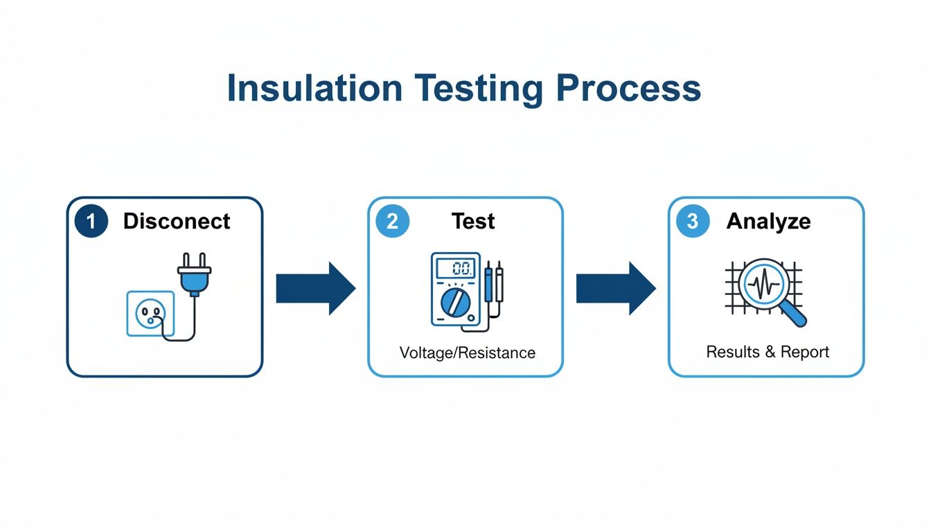
The general process follows a simple, methodical flow: safely isolate the equipment, run the test, and then analyze the results to make an informed decision.
This visual really drives home the core steps. You always start by disconnecting and verifying a zero-energy state. Only then do you apply the test, and finally, you interpret the data you've gathered.
Choosing the Right Ground Fault Test Method
There are a few ways to approach ground fault testing, and picking the right one depends on what you need to verify. Each method has its place, offering a different level of assurance.
This table breaks down the common methods to help you understand their best applications, what they can tell you, and just as importantly, what they can't.
Test Method
Primary Application
Pros
Cons
Push-to-Test Button
Simple go/no-go verification of the relay and trip coil.
Quick and easy; requires no special equipment.
Doesn't test the CT or wiring; doesn't verify pickup or timing accuracy.
Secondary Injection
Verifies relay pickup settings and timing curves.
Highly accurate for testing the relay's logic and calibration.
Bypasses the main current transformer (CT) and its wiring.
Primary Injection
Full system performance test, from the CT to the breaker.
Tests the entire protection chain; the most comprehensive and reliable method.
Requires specialized high-current test set; more time-consuming to set up.
While a push-to-test is a decent spot check, the primary injection method is the gold standard for commissioning and thorough maintenance because it leaves no part of the system unverified.
Setting Up for Primary Current Injection
We're going to focus on the primary injection method because it’s the most thorough way to test a ground fault protection relay in switchgear. This technique uses a high-current test set to push a simulated fault current right through the system's zero-sequence current transformer (CT). It’s the only way to test the entire chain of command, from the CT's ability to sense the fault to the relay's logic and the breaker's physical trip mechanism.
First thing's first: safety. Completely isolate the circuit breaker or switchgear section you're testing. Meticulously follow your LOTO procedure, making sure the equipment is de-energized and verified at a zero-energy state. You'll be working with a test set that can produce thousands of amps, so there's no room for error.
Once the equipment is safely isolated, it's time to connect the high-current test set. The connections are fairly simple but demand precision.
Connect the high-current output leads from your test set so they pass directly through the window of the zero-sequence CT.
The timer input leads from your test set will connect to the breaker’s auxiliary contacts. This is how the test set automatically records the time it takes for the breaker to open after the relay issues its trip command.
This setup creates a controlled, closed loop that perfectly mimics a real-world ground fault, letting you measure the system's actual response.
Calculating Your Test Parameters
Before you inject a single amp, you need to know what you're looking for. The target values for your test are right there on the ground fault relay itself—either on the faceplate dials or within its programming file. You need to find two key settings: the pickup current and the time delay.
Let's walk through a common scenario. Imagine a relay is set for a 100A pickup with a time delay of 0.1 seconds (100 milliseconds).
With these settings, your test needs to verify two things:
Pickup: What is the minimum current that makes the relay operate?
Timing: How long does it take for the breaker to trip at a specific, higher fault current (usually 300% of the pickup setting)?
To check the pickup value, you’ll start injecting current well below the 100A setting and slowly ramp it up. The exact amperage where the relay's "pickup" light comes on is your measured value. It should be right on the money, very close to that 100A setting.
Executing the Test and Verifying Trip Time
Once you've confirmed the pickup value, it's time to check the trip time. This is where you test the system’s reaction speed. Based on the coordination settings, you’ll inject a higher current—a standard practice is to use three times the pickup setting—to simulate a more serious fault.
In our example, that means injecting 300A.
The test set will apply 300A and start its timer at the same instant. The moment the breaker trips, its auxiliary contacts open, which stops the timer. The time displayed is your measured trip time. For our relay set to 0.1 seconds, seeing a result between 95-105 milliseconds would be a solid pass.
The real value of this test is in the data. Documenting the "as-found" settings, the measured pickup current, and the measured trip time creates a baseline for all future maintenance. This record is your proof of compliance and your best tool for tracking the health of your protection system over time.
By comparing these real-world results to the manufacturer's specs and your own coordination study, you'll know everything you need to. If the values are within tolerance, your system is good to go. If not, it's time to start troubleshooting the relay, CT, or breaker before that circuit goes back into service.
Interpreting Results and Troubleshooting Faults
A failed ground fault test isn't a dead end—it's a signpost pointing you toward the real problem. The readings on your meter are clues, and learning how to interpret them is what separates a parts-swapper from a true diagnostician. A low megohm reading or a relay that won't trip is simply the start of a logical troubleshooting process.
This is where you put on your detective hat. The key is to isolate variables systematically. Don’t just assume; prove it with your meter. By breaking a circuit down into its individual components—the cable, the motor, the switchgear—you can pinpoint the exact location of the failure without any guesswork.
The Divide and Conquer Strategy
Let's walk through a common scenario. You run an insulation resistance test on a motor circuit and get a dismal 0.5 MΩ reading. It’s a clear failure. Panic doesn't fix anything, but a solid plan will. The first question is always the simplest: is the problem in the wiring or in the motor itself?
To find out, you need to split the circuit. Get down to the motor's junction box, disconnect the motor leads from the incoming power cable, and then test each piece on its own.
Test the Cable First: With the motor completely out of the circuit, perform the same phase-to-ground insulation test on just the cable. If that reading is still low, you know the fault is somewhere between the starter and the motor j-box.
Then Test the Motor: If the cable tests perfectly (showing hundreds or even thousands of megohms), the fault is almost certainly inside the motor windings.
This simple "divide and conquer" method can save you countless hours of frustration. You've just narrowed a potentially facility-wide headache down to either a specific cable run or a single piece of equipment.
Common Culprits Behind Low Insulation Readings
When an insulation test fails, the root cause is usually some kind of physical damage or contamination. Insulation doesn't just decide to fail on its own; something external causes it to break down.
Here are the usual suspects I look for first:
Moisture Intrusion: Water is electricity’s worst enemy, hands down. A flooded conduit, a leaky seal on a motor peckerhead, or condensation inside a panel are all frequent sources of ground faults.
Heat Damage: Over time, excessive heat from an overloaded motor or just high ambient temperatures can cook insulation until it's brittle. Once it cracks, you've got a ready-made path to ground.
Physical Damage: This is incredibly common, especially during installation. A cable jacket gets nicked while being pulled through a tight conduit, or constant vibration causes a wire to rub against a sharp metal edge inside a panel.
Contamination: In dirty industrial environments, conductive dust from metal grinding or other processes can build up inside equipment, creating a low-resistance path where there shouldn't be one.
A failed test result is just data. The real skill is connecting that data to a physical cause. An intermittent fault that only pops up on rainy days, for instance, is a huge clue that you should be hunting for moisture.
Troubleshooting Failed Relay Performance Tests
So what happens if your insulation tests pass with flying colors, but the ground fault relay itself fails its performance test? This tells you the issue is within the protection system, not the power circuit. If that relay trips too soon, too late, or not at all, your focus needs to shift from insulation to instrumentation.
First things first, double-check the obvious. Are the relay settings correct according to the coordination study? It’s surprisingly common to find that someone programmed the wrong pickup or time delay settings into the device.
If the settings are right, the problem likely lies in the sensing circuit.
Check the CT Wiring: A loose or incorrect connection at the zero-sequence current transformer (CT) is a classic culprit. The relay can't react to a fault it can't see.
Inspect the CT Itself: While rare, current transformers can fail. A damaged or shorted CT simply won't produce the correct secondary current needed to operate the relay.
Understanding these failure modes is crucial for building a complete picture of electrical safety. Sometimes, a persistent ground fault can also be a symptom of a larger issue, which is why it's helpful to understand the various reasons what can cause a breaker to trip beyond a simple fault. After you diagnose and repair the root cause, always re-run your ground fault test to verify the fix before you even think about re-energizing the equipment.
Got Questions About Ground Fault Testing? We've Got Answers.
Even for seasoned pros, a few questions always seem to come up out in the field. Ground fault testing can feel complicated, but once you nail down a few key concepts, you'll have the confidence to get it done right—and safely—every time.
Let's dig into some of the most common questions we hear from technicians and engineers on the floor.
How Often Should I Be Running a Ground Fault Test?
There’s no single, universal answer here. How often you test really boils down to your specific compliance needs and the kind of environment your equipment lives in. But we can map out some solid guidelines that cover most industrial scenarios.
For anything brand new, the rules are black and white. The National Electrical Code (NEC) requires a full performance test on any new ground fault protection system right after it's installed. After that, it becomes a part of your regular preventative maintenance cycle.
For Compliance: The NEC mandates a performance test on initial installation. No exceptions.
For General Maintenance: Following NETA standards is a great baseline. They recommend comprehensive testing every one to three years for most gear.
For Harsh Environments: If your facility deals with high moisture, constant vibration, or conductive dust, don't wait three years. Testing your critical motors and switchgear annually is a smart move that prevents nasty surprises.
What's the Difference Between a GFCI Test and a Ground Fault System Test?
This is a great question because it gets to the heart of a major difference in scale and purpose. They both involve "ground faults," but they are protecting completely different things at wildly different levels.
A GFCI test is a simple life-safety check for a single device, like an outlet near a sink. When you push that little "Test" button, you're just making sure its internal trip mechanism works at a very low leakage current—we're talking just 4-6 milliamperes (mA). It’s all about protecting a person from getting a dangerous shock.
A ground fault system test, on the other hand, is a full-blown diagnostic for your industrial power system. This is a much bigger deal, requiring a proper lockout/tagout and specialized gear like megohmmeters and high-current test sets. The goal here is to confirm the insulation on motors and cables is solid and to prove that your big protective relays will actually trip under massive fault currents to prevent catastrophic equipment damage and fires.
Here’s a simple way to think about it: A GFCI test is like checking the smoke detector in your kitchen. A ground fault system test is like the fire department coming out to test the hydrants and sprinklers for the whole industrial park. Both are critical, but they operate on totally different scales.
Can I Just Use a Multimeter for a Ground Fault Test?
Absolutely not. This is one of the most common and dangerous mistakes we see people make. A standard multimeter is simply the wrong tool for this job; it can't give you the information you actually need.
Your multimeter uses a tiny voltage—maybe just a few volts—to check for things like continuity. It’s perfect for telling you if a fuse is blown, but it's useless for stress-testing insulation. The problem is, insulation often only breaks down when it's hit with a voltage close to what it sees during normal operation.
To do a real ground fault test, you need a proper insulation resistance tester, which most of us just call a megohmmeter. This tool doesn't mess around. It applies a high DC voltage, typically 500V or 1000V, to the conductor. That's enough to properly stress the insulation and reveal any hidden weak spots or leakage paths a multimeter would miss a hundred times out of a hundred. The result is a reading in megohms (MΩ), which is the only true measure of insulation health.
At E & I Sales, we've been designing, building, and troubleshooting complex industrial electrical systems since 1974. Whether you need rock-solid UL-listed control panels, premium motors, or expert system integration, our team has the hands-on experience to deliver the right solution. See how our expertise can power your next project at https://eandisales.com.
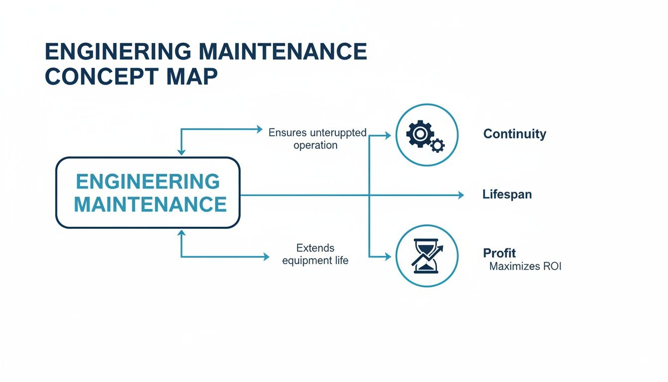
When most people think of "maintenance," they picture a technician with a wrench, fixing something that's already broken. But in the world of industrial operations, that's just a tiny piece of the puzzle. Real engineering maintenance is less about fixing and more about preventing.
More Than Just a Fix-It Crew
Think of it like the pit crew for a Formula 1 car. They aren't just waiting for a tire to blow out. They're constantly monitoring, tweaking, and swapping components to keep that machine screaming around the track at peak performance. That’s the essence of engineering maintenance services. It’s the strategic discipline of keeping your most critical assets—the heart of your operation—running like a Swiss watch.
This is the fundamental shift from a reactive, fire-fighting culture to a proactive, controlled one. Instead of scrambling when a critical motor grinds to a halt and brings your entire production line down, a smart maintenance strategy anticipates the failure before it ever happens. It’s about having experts who understand the intricate language of your machinery, from the subtle vibrations of a generator to the precise calibration of a control panel.
The Real-World Value of Maintenance
Let's be clear: investing in professional engineering maintenance isn't a cost center. It's a direct investment in your company's profitability and resilience. When you have a solid maintenance program in place, you're not just oiling gears; you're protecting your bottom line.
A well-executed strategy directly supports your core business goals:
Getting More from Your Assets: Expert care stops premature wear and tear in its tracks, squeezing every last drop of productive life out of your expensive equipment.
Keeping the Lights On: Proactive maintenance is the enemy of unplanned downtime. It keeps your lines running, your orders shipping, and your customers happy.
Protecting Your Profits: A single catastrophic failure can easily cost millions in lost production, emergency repair bills, and potential safety incidents. Good maintenance is your best insurance policy.
Keeping Your People Safe: There's no way around it—well-maintained equipment is safer equipment. This protects your team and keeps you on the right side of safety regulations.
This isn't just a niche idea; it's a massive, growing industry. The global maintenance services market is a powerhouse, valued at USD 81.86 billion and on track to hit USD 122.09 billion. That’s a 10.5% compound annual growth rate, driven by a global push for sustainability and the urgent need to keep aging infrastructure online. You can dive deeper into the maintenance services market report on researchandmarkets.com.
From massive manufacturing plants to sprawling energy facilities, every industry relies on these specialists to build a foundation of reliability and safety. This proactive mindset is what makes everything else possible, paving the way for the specific strategies we'll get into next.
The Four Core Maintenance Strategies You Need to Know
When it comes to keeping a facility running, there's no single magic bullet. Effective engineering maintenance isn't about a one-size-fits-all approach; it's about having the right tool for the right job. Think of it like taking care of your car—you don't treat a burnt-out headlight the same way you treat a weird noise coming from the engine.
A smart maintenance program blends different strategies to create a balanced, cost-effective plan that keeps the gears turning. Let's break down the four core approaches every plant manager should understand.
As you can see, the end goal is always the same: keep the operation running, get the most out of your equipment, and protect the bottom line. How we get there is where these strategies come into play.
1. Preventive Maintenance: The Scheduled Checkup
This is the one most people are familiar with. Preventive maintenance (PM) is all about routine, scheduled work designed to catch problems before they become catastrophes. It’s the industrial version of changing your car’s oil every 5,000 miles. You do it based on a calendar or a usage meter, not because something is actually wrong.
The triggers are simple: inspect a motor every quarter, or lubricate a bearing after every 1,000 hours of runtime. While it's a massive leap forward from just waiting for things to break, you do run the risk of performing unnecessary work on perfectly healthy components. A well-organized preventive maintenance schedule template is your best friend here, helping you map out and track every task.
2. Predictive Maintenance: The Smart Warning System
Now we're getting smarter. Predictive maintenance (PdM) is a condition-based strategy that relies on real-time data to tell you when a machine needs attention. Think of it as the check engine light on your dashboard—it warns you about low tire pressure before you end up with a flat on the side of the highway.
Using tools like vibration analysis, thermal imaging, and oil analysis, PdM lets technicians see a failure coming. This allows you to step in at the perfect moment—not too early, not too late. You get to maximize the life of your parts, slash maintenance costs, and dramatically reduce unplanned downtime. This data-driven approach is at the heart of modern engineering maintenance services.
3. Corrective Maintenance: The Necessary Fix
Let's be honest: sometimes, things just break. Corrective maintenance—also known as reactive maintenance—is the straightforward strategy of fixing something once it has failed. While it might sound like a plan for disaster, it actually has a strategic place in any good maintenance program.
You wouldn't schedule preventive maintenance for a lightbulb in the breakroom, would you? You just wait for it to burn out and then replace it. The same logic applies to non-critical, redundant, or low-cost assets where the consequence of failure is minimal. The trick is to apply this "run-to-failure" approach intentionally and not let it become the default for your critical machinery.
4. Shutdown Maintenance: The Planned Overhaul
This is the big one. Shutdown maintenance (or a turnaround) is when you take an entire plant or production line offline for a planned period of intensive, large-scale work. It’s like a full frame-off restoration of a classic car—an all-hands-on-deck effort to inspect, repair, and upgrade everything at once.
This strategy is reserved for complex jobs that are simply impossible to do while the plant is running. It demands military-grade planning and coordination to get everything done efficiently before bringing the whole system back online.
Each of these four strategies plays a crucial role. The best maintenance programs don't just pick one; they artfully combine all four based on equipment criticality, failure patterns, and cost.
Comparing Core Maintenance Strategies
To make it even clearer, here's a side-by-side look at how these four strategies stack up against each other.
Strategy Type
Trigger
Primary Goal
Example Application
Preventive
Time or Usage Schedule
Prevent failures before they occur
Quarterly inspection of an HVAC unit
Predictive
Real-time Condition Data
Intervene just before failure
Analyzing motor vibrations to detect bearing wear
Corrective
Equipment Failure
Restore functionality after a breakdown
Replacing a blown fuse on a control panel
Shutdown
Pre-planned Outage
Perform major overhauls and upgrades
Relining a blast furnace during a plant turnaround
As you can see, the trigger for action and the ultimate goal are what really set them apart. By understanding these differences, you can start building a maintenance program that ensures rock-solid reliability without wasting a dime—striking the perfect balance between proactive care and practical reality.
What a Maintenance Partner Actually Covers
So, we've talked strategy. Now, let's get down to the nuts and bolts. When you bring on an engineering maintenance partner, what are they actually doing on your facility floor? This isn't about vague promises; it's about a hands-on partnership designed to protect your most critical assets.
A good service agreement cuts through the fluff and focuses on the specialized electrical and mechanical systems that are the lifeblood of your operation. It’s about having an expert eye on the equipment that, if it goes down, grinds everything to a halt.
Let's pull back the curtain on what's typically covered.
Critical Care for Electric Motors
Think of electric motors as the workhorses of your plant. They run tirelessly, and you absolutely can't afford for them to quit. Maintaining them is a specialized craft.
Motor service goes way beyond a quick shot of grease. We're talking detailed inspections and diagnostics to catch things like bearing wear, insulation breakdown, or slight misalignments before they turn into a catastrophic failure that forces a costly rewind or a full replacement.
Servicing Motor Control Centers (MCCs)
If motors are the muscle, the Motor Control Center (MCC) is the brain. This is where you'll find the starters, variable frequency drives (VFDs), and programmable logic controllers (PLCs) that orchestrate your entire process.
An MCC is a dense, complex hub of electrical gear that needs serious attention. Ignoring it is like never checking the main breaker panel in your house—when something goes wrong here, it can take out an entire wing of your facility. That's why proper motor control center maintenance is non-negotiable for operational stability.
A poorly kept MCC isn't just an operational risk; it's a major safety hazard, with the potential for arc flash incidents. Regular service involves torquing connections, detailed cleaning, and using thermal imaging to find hot spots before they erupt.
Maintaining Custom UL Panels
Your custom UL-certified control panels are the bespoke brains behind specific machines or integrated systems. They’re engineered to run everything from complex automation sequences to critical safety interlocks.
Keeping these panels in top shape means ensuring every relay, breaker, terminal block, and power supply is working exactly as it was designed. This isn't just for reliability—it's essential for keeping the panel's UL listing valid, staying compliant, and guaranteeing the safety of the equipment it commands.
Low to Medium Voltage Switchgear Upkeep
Your switchgear is the gatekeeper of your entire electrical system. It's the first line of defense, protecting all your expensive downstream equipment from overloads and short circuits. It is, without a doubt, one of the most critical pieces of infrastructure you own.
A failure here isn't a minor hiccup. It can trigger a plant-wide blackout and create incredibly dangerous arc flash conditions. Professional engineering maintenance services for switchgear are your direct defense against these high-stakes disasters.
A solid switchgear service plan always includes:
Circuit Breaker Testing: Making sure the breakers will actually trip when they're supposed to.
Protective Relay Calibration: Verifying the "brains" of the gear are correctly set to spot problems.
Busbar Inspection and Cleaning: Preventing dangerous flashovers caused by dust, moisture, or loose connections.
These principles of electrical safety and uptime aren't confined to the factory floor. For a different perspective, this complete guide to EV charger servicing applies a similar logic to public infrastructure. In both worlds, the mission is the same: keep it safe, keep it running, and protect the investment. Once you understand what a true maintenance partner covers—from the motor to the main switchgear—you're in a much better position to know what your facility really needs.
How to Measure Maintenance Success and ROI
Spending on engineering maintenance shouldn't feel like a black box. How do you actually prove that the money you're putting in is a strategic investment and not just another line item on an expense report? The answer is simple: you track the right data and connect it directly to your bottom line.
Vague feelings about "things running better" won't convince a CFO. To justify and optimize your maintenance budget, you have to speak the language of numbers. This means adopting Key Performance Indicators (KPIs) that turn maintenance activities into clear, measurable outcomes that directly impact profitability.
It’s this shift in perspective that's crucial for showing real value and securing ongoing support for your maintenance programs.
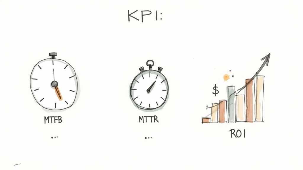
Key Metrics That Tell the Real Story
You don't need dozens of complex formulas to get started. A handful of core KPIs can give you a powerful snapshot of how effective your maintenance program really is. Think of them as the vital signs for your plant's health.
Two of the most fundamental metrics are:
Mean Time Between Failures (MTBF): This is the average time a piece of equipment runs smoothly before it breaks down. A higher MTBF is a crystal-clear sign of improved reliability.
Mean Time To Repair (MTTR): This tracks the average time it takes to get failed equipment back online, from the moment it stops to the moment it's running again. A lower MTTR reflects a more efficient maintenance operation.
Let's put that into perspective. Imagine a critical bottling line conveyor. If its MTBF jumps from 500 hours to 1,500 hours, you’ve just tripled its reliability and slashed production interruptions. If your team also cuts its MTTR from four hours down to one, you're back in business that much faster when a failure does happen.
By focusing on improving just these two numbers, you create a powerful ripple effect. Higher reliability (MTBF) and faster recovery (MTTR) directly translate into more uptime, higher output, and increased revenue.
Calculating the True Return on Investment
Beyond the day-to-day operational metrics, the ultimate measure of success is Return on Investment (ROI). This calculation ties your maintenance spending to tangible financial gains, making the value proposition impossible to ignore.
The ROI formula for maintenance is pretty straightforward:
(Financial Gain from Maintenance – Cost of Maintenance) / Cost of Maintenance
The real trick is accurately calculating the "Financial Gain." This isn’t just about the money you saved on a specific repair; it’s about the massive cost of the downtime you prevented.
Think about this scenario:
A predictive maintenance program costs you $50,000 for the year.
This program helps your team spot a failing gearbox on the main production line before it completely seizes up.
An unexpected failure of that gearbox would have caused 48 hours of downtime, costing $10,000 per hour in lost revenue—that’s a $480,000 loss.
In this case, your $50,000 investment prevented a disaster worth nearly half a million dollars. The ROI is massive, proving that proactive maintenance isn't a cost center; it's a high-yield investment. This financial reality is driving huge growth, with the maintenance and support segment projected to hit USD 753.5 million. In North America, companies are already cutting unplanned downtime by 30-40% by outsourcing maintenance and using predictive analytics. You can dig into more of these engineering services market trends on grandviewresearch.com.
Building a Culture of Measurement
Putting KPIs in place is more than just a technical exercise—it’s a cultural shift. It means getting serious about collecting data consistently, reporting it clearly, and committing to using those insights to get better every day.
Start by getting a baseline for your most critical assets. Once you know where you stand, you can set realistic targets for improvement and track your progress. This data-driven approach is what transforms maintenance from a necessary evil into a strategic driver of operational excellence and, ultimately, profitability.
Choosing the Right Engineering Maintenance Partner
Picking an engineering maintenance services partner is one of the biggest calls an operations manager has to make. This isn't just about getting someone to fix what’s broken. You're building a strategic relationship that has a direct line to your plant's safety, uptime, and bottom line.
The right partner feels like a natural extension of your own team. The wrong one? They can become a constant source of risk, inefficiency, and headaches. You need to look past the price tag and take a methodical approach to find a provider who truly gets your operation and shares your commitment to safety.
Do They Have the Right Kind of Experience?
First things first, your partner needs to have serious technical chops in your specific world. A team that excels in food and beverage processing understands sanitary standards and the relentless pace of production in a way that an oil and gas specialist simply won't.
Don't be shy about asking for proof. Request case studies or, even better, references from companies that look a lot like yours. You're looking for verifiable expertise—certified technicians and engineers who know their way around everything from your medium voltage switchgear to the PLCs running your lines. As facility owners know, a partner who can work with your existing digital tools is a huge plus, which is why integrating BIM for owners in maintenance planning has become such a critical conversation.
Often, the best partners go beyond just repairs. They can act as an effective industrial automation system integrator, helping you find new ways to improve your entire process.
A Rock-Solid Safety Record Isn't Negotiable
In our world, safety is everything. A provider's safety record is a crystal-clear indicator of their discipline and professionalism. It tells you exactly how they’ll operate when they’re on your floor.
Here’s what to look for:
Experience Modification Rate (EMR): An EMR under 1.0 is the gold standard. It shows they are statistically safer than the industry average.
OSHA Compliance: Ask them directly about their history of OSHA recordable incidents and the safety programs they have in place.
Technician Training: How do they train their people? Dig into their safety protocols, certifications, and what they do for ongoing education.
A partner with a stellar safety record isn't just protecting their own crew. They're protecting your people, your equipment, and your business from liability and disaster.
Understanding the Money: Comparing Pricing Models
You need to know how a potential partner bills so you can budget properly and make sure you're getting real value. It usually comes down to two main approaches.
1. Fixed-Fee Contracts You pay one set price for a clearly defined list of services over an agreed-upon time. This model gives you predictable costs, which is perfect for routine preventive maintenance schedules where there are few surprises.
2. Time-and-Materials (T&M) Contracts With T&M, you're billed for the actual hours worked plus the cost of any parts or materials used. It’s a flexible model that works well for unpredictable corrective maintenance jobs or special projects where it's tough to nail down the full scope from the start.
The global engineering services market is huge, valued at around $2.0 trillion. This is driven by all sorts of regional needs, like the push in North America for energy-efficient retrofits to cut operational risks. Getting the pricing model right is your first step in tapping into these services effectively.
Your Engineering Maintenance Questions Answered
Diving into industrial upkeep always stirs up a few questions. Picking the right strategy—or the right partner—for your engineering maintenance services is a big deal, and you need straight answers. Let's tackle some of the most common questions we hear from plant managers and engineers to give you that clarity.
What Is the Difference Between Facility Maintenance and Engineering Maintenance?
It’s easy to lump all maintenance into one bucket, but they’re two completely different animals.
Think of it this way: facility maintenance takes care of the building itself. Engineering maintenance takes care of the highly specialized production equipment inside that building.
Facility Maintenance is all about the building’s core infrastructure. We're talking HVAC repairs, plumbing, lighting, and general structural work needed to keep the place safe and comfortable.
Engineering Maintenance, on the other hand, is laser-focused on the complex machinery that actually makes your product. This means servicing things like electric motors, custom UL control panels, and medium-voltage switchgear—assets that demand certified engineering know-how to handle safely.
One keeps the roof over your head, and the other keeps your production lines moving.
The distinction is critical. Your facility tech can fix a leaky pipe, but only a qualified maintenance engineer can properly diagnose and service the variable frequency drive running your main conveyor system.
How Can a Small Business Afford Comprehensive Maintenance Services?
If you're running a smaller operation, a full-blown maintenance contract can sound like a budget-buster. But you don't need an all-or-nothing plan to get real results. Smart, targeted strategies make professional maintenance totally accessible.
The best place to start? Identify your most critical assets. Pinpoint the handful of machines that would cause the most financial pain if they went down. From there, you can build a focused preventive maintenance plan just for that high-priority equipment. It's a surgical approach that delivers the most bang for your buck.
Another great option is a retainer-based contract for corrective maintenance. This gives you an expert on-call when you need one most, without the overhead of a full-time, in-house team. It's a model that gives you peace of mind and scales right alongside your business, offering a practical path to better reliability.
What Role Do AI and IoT Play in Modern Maintenance?
This isn't just hype. Artificial Intelligence (AI) and the Internet of Things (IoT) are completely changing the maintenance playbook. They’re helping us shift from being reactive to being predictive, giving teams the power to stop failures before they ever happen. It’s a massive leap forward.
IoT sensors are like a 24/7 health monitor for your equipment. You place them on motors, pumps, and other critical assets, and they constantly collect real-time data on vibration, temperature, and energy use. This firehose of information is where AI steps in.
AI algorithms chew through all that data, spotting subtle patterns a human could never see. The system can then predict when a part is likely to fail, giving you a heads-up weeks or even months in advance. This move to condition-based maintenance is just incredibly efficient—it gets rid of unnecessary scheduled work and helps you squeeze every bit of productive life out of your most important assets.
At E & I Sales, we know that reliable equipment is the backbone of your operation. We bring the expert support, custom control solutions, and deep product knowledge you need to keep your facility running at its absolute best. Let's build a more reliable future for your plant together.