A multiwire branch circuit (MWBC) is one of those clever wiring tricks that saves a ton of material and labor on the job site. At its heart, it’s a setup where two or more circuits share a single neutral conductor.
Think of it like an electrical carpool lane. Instead of every car needing its own dedicated lane back to the start, multiple lanes of traffic (the hot wires) merge into one shared return lane (the neutral wire). It's a simple concept that makes a big impact.
What Are Multiwire Branch Circuits and Why Use Them
So, how does it work without overloading that one neutral wire? An MWBC isn't just about bundling wires together; it relies on a fundamental electrical principle. The two ungrounded (hot) conductors must be connected to different phases, or legs, of the electrical service.
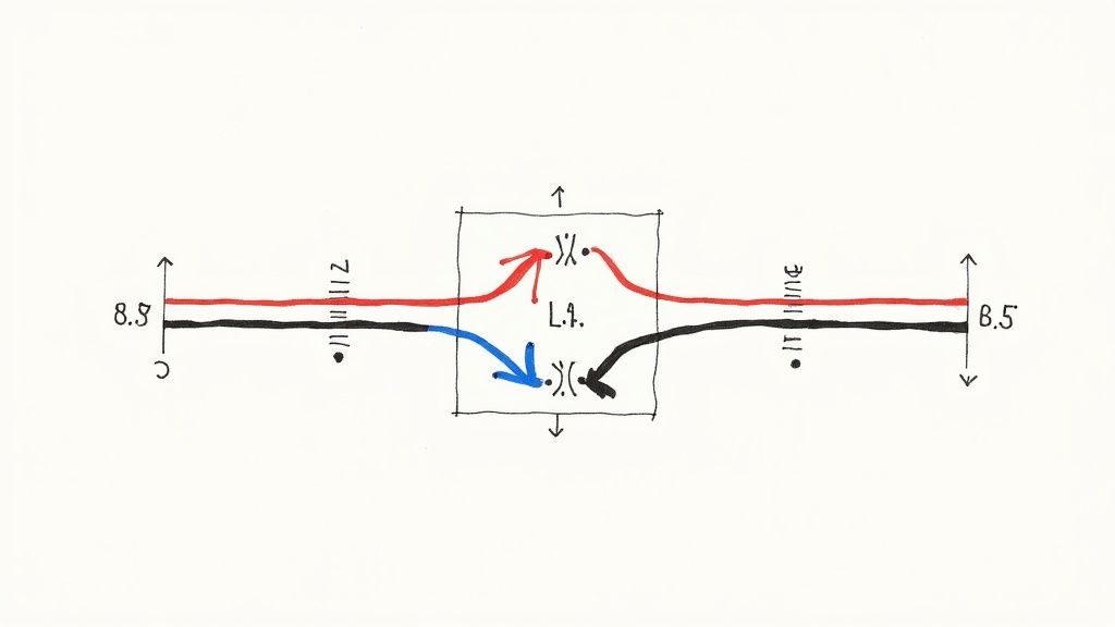
In a standard single-phase 120/240V system, this means one hot wire lands on Leg A and the other on Leg B. This opposition is the secret sauce that makes the whole thing work safely.
The Principle of Current Cancellation
The real magic happens on that shared neutral. Because the hot wires are on opposite phases, their alternating currents are 180 degrees out of sync with each other. When one is pushing, the other is pulling.
This means the current on the shared neutral isn't the sum of the two circuits, but the difference between them. This is what we call the unbalanced load. For instance, if one circuit is pulling 12 amps and the other is pulling 10 amps, that shared neutral only has to carry 2 amps back to the panel. If you managed to perfectly balance the loads at 10 amps each, the neutral would carry zero current.
Key Advantages for Industrial Applications
This clever bit of physics delivers some serious practical benefits, especially in industrial plants and commercial buildings where you're dealing with long runs and lots of circuits.
Reduced Material Costs: This is the big one. Fewer conductors mean less copper. Running a single 12/3 cable instead of two separate 12/2 cables adds up to huge savings on large projects.
Smaller Conduit Fill: With fewer wires to pull, you can often get away with smaller conduit. Or, you can pack more circuits into existing conduit without violating fill codes, which saves a lot of headaches during retrofits.
Lower Voltage Drop: Because the current on the neutral is often much lower than the current on the hots, it helps minimize voltage drop, especially over long distances. That means more stable power for your sensitive equipment.
This technique is nothing new; it’s been around since the early days of electrical distribution. In fact, some old-school electricians still call them 'Edison circuits' because of their historical connection to Thomas Edison's original three-wire systems. You can get more insights on the historical context of circuit protection and its evolution from sources like HomeInspector.org.
By sharing a single neutral, an MWBC effectively turns two circuits into a more streamlined, three-wire system. This efficiency is why plant engineers and system integrators continue to specify them for applications like office cubicles, lighting grids, and equipment racks.
Getting the NEC Safety Requirements Right
Look, multiwire branch circuits are fantastic for saving on wire and labor. But that efficiency comes with a catch: you have to be absolutely rigorous about following the safety rules in the National Electrical Code (NEC). These aren't just suggestions; they’re designed to prevent some very specific, very dangerous situations that can pop up with an improperly wired MWBC.
For any plant engineer, integrator, or electrician on the floor, getting these rules down cold is non-negotiable. Getting it wrong can lead to nasty electrical shocks, fried equipment, and having to tear everything out and start over. Let's break down the most critical section, NEC 210.4.
The All-Important Disconnecting Means
This is the absolute cornerstone of MWBC safety: you must have a way to shut off all the "hot" conductors at the same time. It’s a master-off switch for the entire circuit. When you flip that breaker, everything connected to it—both hot legs and that shared neutral—must go dead simultaneously.
Why is this a life-or-death rule?
Picture a technician working on a receptacle. They trace the circuit back to the panel, find what they think is the right breaker, and shut it off. Feeling safe, they open up the neutral wire. But here’s the problem: the other hot leg of the MWBC is still live and pulling a load.
The instant that neutral is disconnected, the return current has nowhere to go… except through the technician. That supposedly "dead" neutral wire they're holding instantly becomes energized at 120 volts. It's a terrifying and completely avoidable scenario.
NEC 210.4(B) Disconnecting Means "Each multiwire branch circuit shall be provided with a means that will simultaneously disconnect all ungrounded conductors at the point where the branch circuit originates."
This is exactly why you're required to use either a 2-pole or 3-pole common trip circuit breaker. Another option is using individual single-pole breakers, but only if they're physically connected with an approved handle tie. This makes it impossible for someone to accidentally kill power to just one part of the circuit.
Grouping and Identifying Your Conductors
The NEC doesn't stop at the panel. It also demands that all conductors in an MWBC are grouped together for the entire run. From the breaker to the very last outlet, these wires need to stick together.
Using Multi-Conductor Cable: If you're running something like a 12/3 Romex or MC cable, you're already covered. The wires are bundled in the sheathing.
Pulling Wires in Conduit: When you're pulling individual THHN wires through conduit, you have to physically group them. Use cable ties or similar fasteners inside boxes and panels to make it obvious they belong to the same circuit.
This isn't just about neatness. It’s about preventing a deadly mix-up down the road. When the next electrician opens a junction box, they need to see at a glance which wires are a team. A loose, ungrouped neutral from a live MWBC could easily be mistaken for a spare from a different, de-energized circuit, leading right back to that open-neutral hazard. Properly managing circuit integrity is crucial, whether you're working on a plant floor or planning a home electrical panel upgrade.
The Tricky Rules for GFCI and AFCI Protection
Adding Ground-Fault (GFCI) or Arc-Fault (AFCI) protection to an MWBC isn't as simple as slapping in a standard device. If you use a single-pole GFCI or AFCI breaker or receptacle, you're in for a world of headaches.
The shared neutral is the culprit. These devices work by sensing an imbalance between the current on the hot and the neutral. On an MWBC, the neutral carries the unbalanced current from both hot legs, so a standard single-pole device will constantly see an "imbalance" and do its job: trip.
To get it right, you have two options:
Use a 2-Pole GFCI/AFCI Circuit Breaker. This is the cleanest, most reliable solution. A 2-pole breaker is designed for an MWBC. It monitors both hot conductors and the shared neutral together, so it knows what normal operation looks like and won't nuisance trip.
Install GFCI Receptacles at Each Outlet (with care). You can do this, but it’s tricky. You have to carefully pigtail the neutral at each box and be meticulous about the line/load connections. It’s far easier to make a mistake this way than by simply using the correct 2-pole breaker from the start.
Mastering these safety rules is just as vital as knowing the wire sizing and overcurrent protection details found in the NEC Tap Rule. A proper disconnecting means, clear conductor grouping, and the right fault protection are the three pillars that make MWBCs both a smart and a safe choice.
How to Properly Balance Loads and Size Neutral Wires
The real magic of a multiwire branch circuit is how it manages return currents, but unlocking that efficiency comes down to one critical principle: load balancing. In a perfect world, the loads on each ungrounded (hot) conductor would be identical. Their opposing currents would cancel each other out, and the shared neutral would carry absolutely nothing.
Of course, we don't work in a perfect world. Industrial and commercial environments are messy and unpredictable. The goal isn't perfection; it's reasonable balance. When a load is unbalanced, the shared neutral has to carry the difference in current between the phases. Getting a handle on this is non-negotiable for safety and performance.
The Dangers of Unbalanced Loads
Let's picture a simple 120/240V single-phase MWBC feeding a row of twenty workstations, each with a computer and a monitor. If ten stations are wired to Phase A and ten are on Phase B, the loads will probably be pretty close. But what happens when the IT department takes half the computers on Phase B offline for an update?
Suddenly, you could have Phase A pulling 14 amps while Phase B is only drawing 2 amps. That shared neutral is now carrying the 12-amp difference. This is a normal, safe condition—the neutral is sized to handle the full current of any single phase.
The real trouble starts when the loads aren't just unbalanced, but are dominated by modern electronics.
Harmonic Currents: The Hidden Neutral Overload
Non-linear loads are everywhere in today's plants and facilities. Think computers, variable frequency drives (VFDs), LED lighting drivers, and just about any device with a switch-mode power supply. Unlike a simple resistive load (like an old-school heater), these devices draw current in short, choppy pulses instead of a smooth sine wave.
These pulses create harmonic currents—basically, electrical noise at multiples of the standard 60 Hz frequency. On a balanced three-phase system, a funny thing happens: the third-order harmonics (180 Hz) from each phase don't cancel out on the neutral. They actually add together.
This creates an incredibly dangerous situation where your phase conductors might be well within their limits, but the neutral conductor is silently overheating from these additive harmonic currents. In some extreme cases, the current on the neutral can climb to 1.73 times the phase current.
Key Takeaway: When you're running non-linear loads on an MWBC, you can't just assume the neutral current will be low. Harmonic distortion can turn that shared neutral into a serious fire hazard if you don't size it correctly.
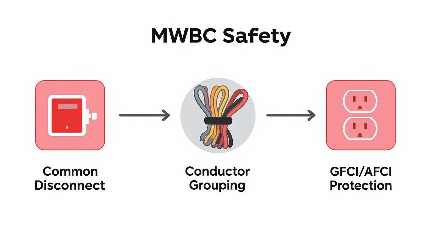
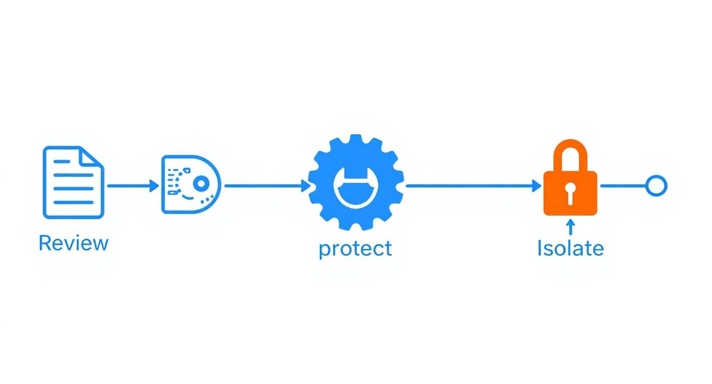
The infographic below breaks down the essential safety pillars—from the panel to the outlet—that you need to have in place to manage these risks.
This shows that safety isn’t a single step. It starts with a common disconnect, requires proper conductor grouping in the conduit, and ends with the right kind of fault protection.
Sizing the Neutral Conductor Correctly
The National Electrical Code (NEC) doesn't mess around here. NEC 220.61 is clear: if a "major portion" of the load on a three-phase, four-wire MWBC is non-linear, you must count the neutral as a current-carrying conductor when you calculate ampacity adjustments (derating).
If you expect significant harmonics, you may need to go a step further and actually upsize the neutral conductor. Field studies in mission-critical facilities back this up, showing that balanced current loads are virtually nonexistent, leading to efficiency-killing harmonics.
Here's a quick cheat sheet for neutral sizing:
Standard Loads: For circuits with mostly linear loads (incandescent lights, resistance heaters), the neutral can be the same size as the phase conductors.
Non-Linear Loads: If you're feeding computers, office equipment, or electronic lighting, that neutral wire officially counts as a current-carrying conductor.
Heavy Harmonics: In environments packed with VFDs and switch-mode power supplies, it's common practice to oversize the neutral. A popular approach is to use a neutral conductor rated for 200% of the phase conductor ampacity.
To illustrate how the math works out in different situations, let's look at a few examples.
MWBC Neutral Current Calculation Scenarios
The table below shows how the neutral current changes based on the type of system and the balance of the loads.
Scenario
Phase A Current
Phase B Current
Phase C Current
Calculated Neutral Current
Balanced Single-Phase
15 A
15 A
N/A
0 A (15A – 15A = 0A)
Unbalanced Single-Phase
15 A
5 A
N/A
10 A (15A – 5A = 10A)
Balanced Three-Phase
15 A
15 A
15 A
0 A (Vector sum is zero)
Unbalanced Three-Phase
15 A
10 A
5 A
8.66 A (Vector sum calculation)
As you can see, even in a "perfectly" balanced three-phase system, the neutral current is zero. But once the loads become unbalanced, the neutral immediately starts carrying current.
Proper sizing doesn't just prevent overheating; it helps with other power quality headaches, too. For a deeper look at how wire size affects system performance, check out our guide on voltage drop calculation formulas. It’s a huge factor in keeping equipment running smoothly, especially over long distances.
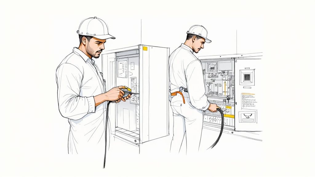
Practical Wiring Methods and Installation Best Practices
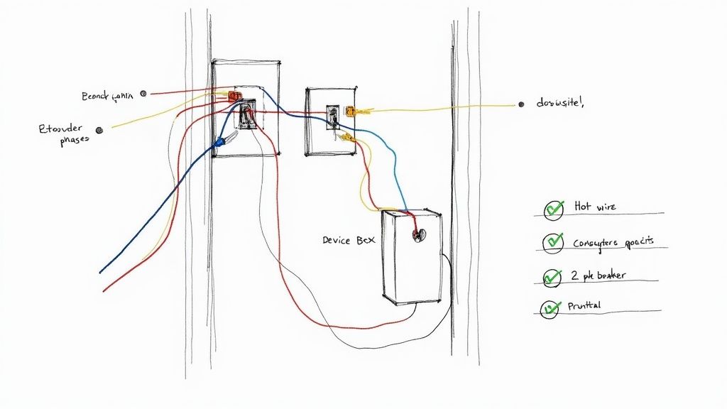
Moving from theory to practice is where the rubber meets the road with multi-wire branch circuits. Proper installation is the final, critical step that ensures an MWBC operates safely and efficiently for years to come. Getting the details right—from the panel to the last device—is absolutely essential for compliance and reliability.
The diagram above gives you a good look at a typical layout, but the core principles apply to any setup. Let's break down the most common configurations and highlight the best practices that prevent the most dangerous installation errors.
Landing Hot Wires on Opposite Phases
If you remember one thing, make it this: landing your hot conductors on different phases is the single most important step in wiring an MWBC. The entire concept of neutral current cancellation hinges on this. If they land on the same phase, that shared neutral will carry the sum of their currents, not the difference.
Picture two circuits, each pulling 15 amps. Wired correctly to opposite phases (say, Phase A and Phase B), the neutral only has to handle the unbalanced load. But if you accidentally land them both on Phase A, that neutral wire is now trying to carry a staggering 30 amps. That's a guaranteed overload that will melt insulation and create a serious fire hazard.
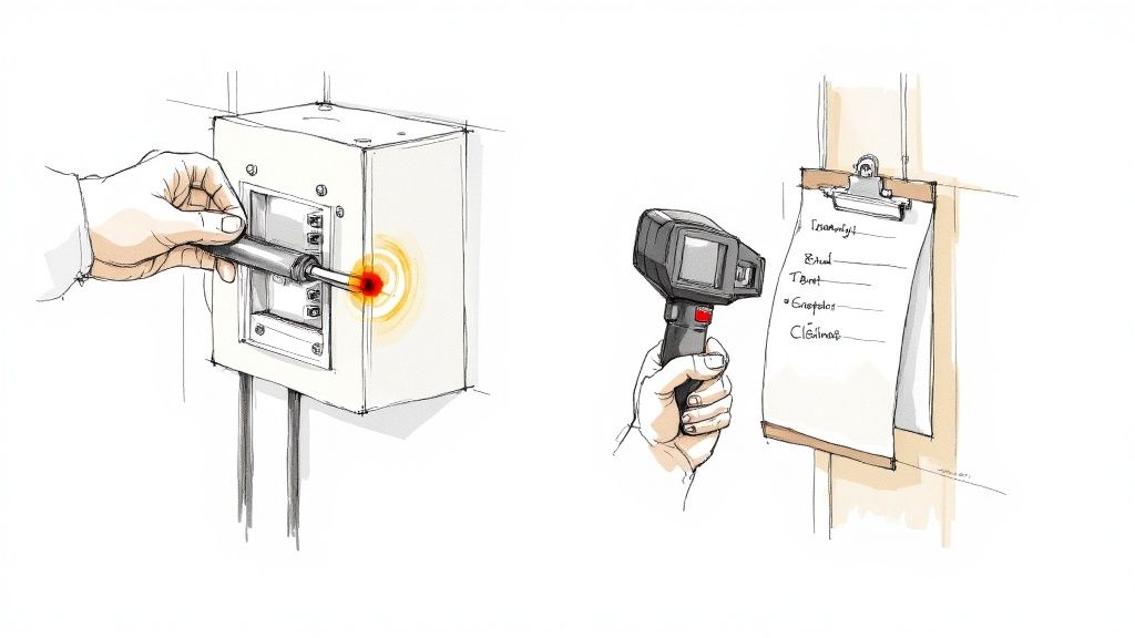
Critical Safety Check: Always use your voltmeter to confirm there is 240V (for a single-phase panel) or 208V (for a three-phase system) between the hot conductors of your MWBC. If you measure 0V, they are on the same phase and you need to fix it immediately.
Best Practices for Conductor Management
Once you leave the panel, keeping the MWBC conductors organized is just as important. A rat's nest of wires inside junction boxes or conduits is a recipe for dangerous mix-ups during future maintenance or troubleshooting.
Here are the non-negotiable rules for managing your conductors in the field:
Group Conductors Together: The NEC is clear on this—all wires of an MWBC must be grouped together. If you're pulling individual conductors in a raceway, use wire ties or another method to keep them bundled inside enclosures.
Pigtail Neutrals in Device Boxes: This is a big one. Never use the terminals on a receptacle to "daisy chain" the shared neutral from one device to the next. If that receptacle fails or gets removed, you've just created a hazardous open-neutral situation for everything downstream. Always connect the incoming and outgoing neutrals with a pigtail, sending just a single wire to the device.
Maintain Consistent Color Coding: Stick to standard color codes (e.g., black and red for 120/240V; black, red, and blue for 120/208V). This simple habit makes it easy to identify your ungrounded conductors throughout the entire circuit run, saving time and preventing costly errors.
Properly managing conductors also means choosing the right enclosures. To learn more about selecting the correct hardware for your installation, you can explore the different electrical boxes types available.
Step-By-Step Installation Checklist
To make sure every MWBC installation is safe and compliant, follow this systematic process. Think of it as a framework for both new installations and for auditing existing circuits.
Plan the Circuit: Identify the loads and confirm they're a good fit for an MWBC. Calculate potential unbalanced loads and consider any harmonic content.
Select the Right Breaker: Choose a 2-pole or 3-pole common-trip breaker. If using single-pole breakers, make sure they have an approved handle tie.
Land and Verify Phasing: Connect your hot wires to opposite phases at the panel. Use a multimeter to confirm the voltage between them is not zero.
Group All Conductors: Run a multi-conductor cable or bundle individual wires in conduit for the entire circuit length. Keep them together.
Pigtail All Neutrals: In every single junction and device box, use pigtails for the shared neutral to maintain circuit integrity. No exceptions.
Install GFCI/AFCI Protection Correctly: The best and most reliable way to do this is with a 2-pole GFCI/AFCI breaker. Steer clear of using single-pole devices on MWBCs.
Label the Panel: Clearly mark the MWBC in the panel directory. Make a note indicating which circuits are part of the shared neutral setup. This simple documentation is a critical safety measure for the next person who works on that panel.
Troubleshooting Common Faults and Safety Hazards
While a multi-wire branch circuit can save you a bundle on wire and labor, that shared neutral wire introduces some unique and downright dangerous failure modes. Every plant engineer and electrician needs to know these failure signatures by heart. Getting it wrong during troubleshooting doesn't just mean a callback; it can lead to catastrophic equipment damage or a life-threatening shock.
This is your field guide to the most common MWBC problems, starting with the absolute worst-case scenario: the open neutral.
An open or "lost" neutral is the Achilles' heel of an MWBC. When that shared return path gets broken somewhere between the load and the panel, the circuit doesn't just go dead. Instead, the loads on the two separate phases get wired in series across the full 240 volts.
Diagnosing the Treacherous Open Neutral
The dead giveaway of an open neutral is wild voltage swings. One leg of the circuit gets hit with a dangerous over-voltage while the other leg is starved with an under-voltage. On a standard 120/240V MWBC, you might measure a staggering 170V at one receptacle and a measly 70V at its counterpart. That kind of voltage spike will instantly fry sensitive electronics, control boards, and small motors.
If you get a call about flickering lights or a whole bank of equipment suddenly dying, an open neutral should be the first thing on your mind. Here’s how to systematically track it down:
Start at the scene of the crime: Grab your multimeter and check the voltage right at the affected outlets or equipment terminals. If you see unstable or wildly incorrect voltages, you're on the right track.
Trace the neutral back: Work your way backward from the load, meticulously inspecting every single neutral connection. Check the terminals in junction boxes, device boxes, and especially at the neutral bus bar in the panel.
Look for the weak link: More often than not, the culprit is a loose wire nut, a failed back-stab connection on a cheap receptacle, or a wire that has simply vibrated loose over time in an industrial environment.
Safety Warning: Never, ever disconnect the neutral wire on a live MWBC. If there's any load on the hot conductors, that neutral is carrying the unbalanced current. Breaking that connection makes you the new path to ground, creating a serious shock hazard. Always kill the power to the entire circuit at the common-trip breaker before you touch a single wire.
Improper Breaker Setups and Other Hazards
Beyond the open neutral, a few other installation mistakes can create ticking time bombs. One of the most common is failing to use a proper common-trip breaker or at least a handle tie, which is a direct violation of NEC 210.4. When an installer just slaps two single-pole breakers next to each other, someone can easily shut off one phase for service while leaving the other one live. This creates the exact scenario where an unsuspecting technician gets zapped by a neutral wire they thought was dead.
This very safety issue is at the heart of an ongoing debate about using MWBCs versus running dedicated neutrals. The potential for neutral conductor overloads and fire risks has pushed the National Electrical Code (NEC) to mandate common-trip protection. Still, some experts argue that the risks aren't worth the savings, advocating for dedicated neutrals in all commercial and industrial settings. You can dive deeper into the evolution of these safety rules in various electrical system analyses, like this discussion on multiple circuits and safety considerations on scribd.com.
For critical industrial equipment like PLCs, VFDs, and sensitive control systems, the choice is clear for many engineers. They specify dedicated neutrals from the get-go. It eliminates the risks of shared wiring, from harmonic current issues to the ever-present danger of an open neutral. While a perfectly installed MWBC is code-compliant, the high-stakes environment of a modern plant often justifies the extra cost of separate neutrals for maximum reliability and safety.
A Few Common Questions From the Field
Even when you have the theory down cold, multi-wire branch circuits have a way of throwing a few curveballs on the job site. These circuits touch on so many specific corners of the National Electrical Code (NEC) that knowing how to handle common situations is key to a safe, compliant install.
Let's tackle some of the most frequent questions that pop up for plant engineers, electricians, and integrators working with MWBCs. We'll cut through the confusion with clear, direct answers to help you make the right call.
Can I Use a Multiwire Branch Circuit for Kitchen Countertops?
The short answer is yes, you can use an MWBC for the small-appliance circuits in a kitchen, but the rules are incredibly strict. Kitchens are a bit of a special case, needing at least two dedicated circuits for those countertop receptacles. An MWBC is often the go-to for running this efficiently.
Here's the catch: these circuits demand ground-fault protection. You can't just slap two separate GFCI receptacles on the same MWBC. Because of that shared neutral, you'll create an imbalance that causes constant, maddening nuisance tripping.
The only way to do this right is to put the protection at the source. That means you must use a 2-pole GFCI circuit breaker in the panel. This single device protects both circuits, properly monitors the shared neutral, and checks the box for the NEC's simultaneous disconnect requirement.
What Happens If Both Hot Wires Are on the Same Phase?
This is, without a doubt, one of the most dangerous mistakes you can make with an MWBC. Wiring both hot conductors to the same phase completely destroys the principle of current cancellation that makes the circuit work, creating an immediate and serious fire hazard.
An MWBC is designed so the opposing currents from different phases cancel each other out on the shared neutral. But when you land both hots on the same phase, the currents are no longer opposing—they're working together. Instead of canceling out, they add together on the neutral.
Think about it: if one circuit pulls 15 amps and the other also pulls 15 amps, that neutral wire is suddenly forced to carry a staggering 30 amps. A 12-gauge wire, sitting behind a 20-amp breaker, will overheat and melt its insulation long before that breaker even thinks about tripping. That's a recipe for an electrical fire, and it's why you must always verify you have 240V (or 208V in a 3-phase system) between the hot conductors at the panel.
Are Multiwire Branch Circuits Being Phased Out?
Not at all. Multi-wire branch circuits are not being removed from the NEC, and they remain a perfectly valid and cost-effective wiring method. What has happened is that the safety rules around them have gotten tighter over the years to patch up historical risks and head off common installation mistakes.
The biggest game-changer was the mandate in NEC 210.4 for a simultaneous disconnecting means. This rule, which requires a common-trip multi-pole breaker or an approved handle tie, was put in place to eliminate the deadly open-neutral hazard that could happen if a technician only shut off one leg of the circuit for maintenance.
While MWBCs are perfectly fine when installed by the book, some engineers and designers are now opting for dedicated neutrals for every circuit, especially in critical or sensitive industrial settings. It simplifies troubleshooting and completely sidesteps the unique risks of a shared neutral. In the end, the choice often comes down to balancing the material cost savings of an MWBC against the simplicity and risk profile of the application.
At E & I Sales, we specialize in providing reliable, code-compliant solutions for complex industrial applications. Whether you're designing a new system or upgrading an existing facility, our team offers the deep product expertise and practical field experience to ensure your motor control, automation, and power distribution projects are a success. Connect with us today to discuss your next project.
Think of ground fault protection as your electrical system's personal bodyguard. It’s an incredibly fast safety switch that monitors your wiring for any sign of trouble. The moment it detects electricity straying from its intended path—a dangerous situation known as a ground fault—it snaps into action, shutting down the power in a fraction of a second to prevent a nasty electric shock.
That immediate, life-saving response is what makes it so indispensable in our homes, on job sites, and anywhere electricity is used.
What Is Ground Fault Protection and Why Is It Essential
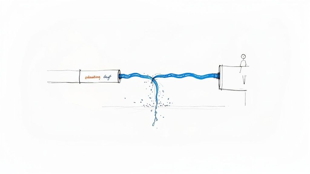
Let's use an analogy. Imagine your electrical circuit is a closed-loop plumbing system. The electricity is like water, flowing from the source, through your tools or appliances, and then returning to the source. Everything is contained.
A ground fault is what happens when that system springs a leak. The electricity escapes its intended path and finds a shortcut to the ground.
That leak can be incredibly dangerous. If a person accidentally becomes that shortcut—say, by touching a faulty piece of equipment while standing in a puddle—the resulting electric shock can be severe, or even fatal. This is precisely where ground fault protection proves its worth.
Protecting People First and Foremost
When we talk about ground fault protection, the number one priority is almost always people. It doesn't take much electrical current to cause serious harm, far less than what it takes to trip a standard circuit breaker. Those breakers are designed to protect equipment and wiring from overheating, not to save a person's life. They simply aren't sensitive enough for the job.
This brings us to the two distinct goals of electrical protection:
Personnel Protection: This is all about preventing electrocution. These devices are fine-tuned to detect tiny, almost imperceptible current imbalances—as little as 4-6 milliamperes—and trip instantly.
Equipment Protection: The focus here is on shielding expensive machinery like motors, generators, and transformers. These systems are designed to stop higher-level ground faults that could lead to fires or catastrophic equipment failure.
While both types of protection are critical, keeping people safe is the non-negotiable mission in nearly every setting.
A ground fault is an unintended electrical path between a power source and a grounded surface. Ground fault protection devices are designed to interrupt this dangerous flow of electricity before it can cause serious injury or death.
The widespread adoption of these systems has fundamentally changed electrical safety for the better. As experts at NK Technologies explain in their resources, a huge number of potential disasters are quietly prevented every day because these devices do their job.
Personnel vs Equipment Protection At a Glance
To really get a feel for these two functions, it helps to put them side-by-side. Think of one as a hyper-alert bodyguard for people and the other as a heavy-duty security guard for your expensive gear.
This table breaks down the key differences:
Aspect
Personnel Protection (e.g., GFCI)
Equipment Protection (e.g., GFPE)
Primary Goal
Prevents electric shock and saves lives.
Prevents damage to electrical equipment and fires.
Sensitivity
Extremely high; trips at very low currents (4-6 mA).
Lower; trips at higher currents (e.g., 30 mA to several amps).
Response Time
Extremely fast, typically within 20-30 milliseconds.
Slower, may have an intentional time delay to avoid nuisance trips.
Common Location
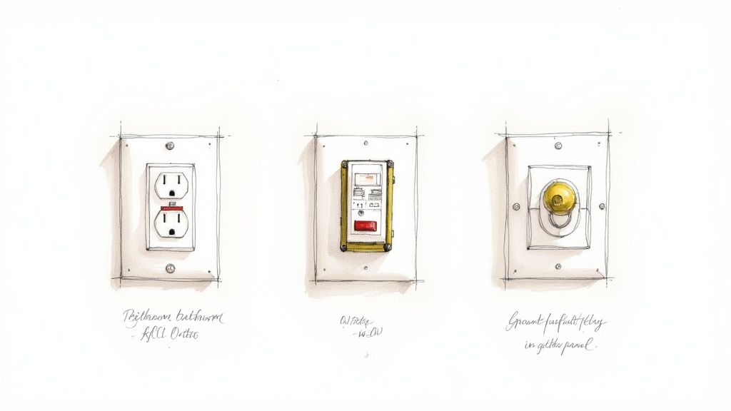
Bathrooms, kitchens, outdoor outlets, and wet areas.
Main service panels, feeders, and large motors.
Ultimately, both play a vital role in a safe, reliable electrical system. One keeps you safe, and the other keeps your operations running without burning down.
Understanding Different Ground Fault Protection Devices
While the goal of ground fault protection is always the same—stopping dangerous electrical currents in their tracks—the tools for the job aren't one-size-fits-all. Different devices are engineered for very different scales, from protecting a single person plugging in a hairdryer to safeguarding an entire industrial plant.
Think of it like securing a building. You’d use a simple lock on an interior office door, but a far more complex system for the main entrance and vault. Electrical safety is no different. It uses a whole range of devices to build a complete safety net, layer by layer. Let’s break down the most common players you'll run into.
Ground-Fault Circuit Interrupters (GFCIs)
For most people, the GFCI is the face of ground fault protection. It’s that outlet with the little "TEST" and "RESET" buttons you see in kitchens, bathrooms, and garages. The GFCI is your personal bodyguard, standing watch right at the point of use.
How it works is both simple and brilliant. A GFCI constantly monitors the electricity flowing out on the "hot" wire and coming back on the "neutral" wire. In a healthy circuit, these two currents are perfectly balanced.
But if that balance is off by just a tiny amount—as little as 4 to 6 milliamperes—the GFCI assumes the missing current has found another path to ground. A dangerous path, possibly through you. It doesn't wait to find out. In a flash (20-30 milliseconds), it trips and cuts the power, stopping a potentially lethal shock before it can happen.
A GFCI's sole mission is personnel protection. Its speed and sensitivity are finely tuned to react long before an electrical current can cause serious harm to the human body.
Residual Current Devices (RCDs)
Think of a Residual Current Device (RCD), sometimes called a Residual Current Circuit Breaker (RCCB), as a GFCI for a whole circuit. While a GFCI outlet protects whatever is plugged into it, an RCD is installed back in the breaker panel to watch over an entire circuit branch.
It does the same life-saving job, just on a bigger scale. By monitoring the current balance for all the outlets and equipment on that circuit, it provides widespread protection. This is a really efficient way to cover areas with multiple potential hazards, like a whole workshop or a string of outdoor lights. While common in European systems, they work on the same core principle as the GFCIs we see every day. To get a better handle on the different safety devices out there, it’s worth understanding the distinction between AFCI and GFCI devices.
Ground-Fault Relays and Equipment Protection
Now we're moving from protecting people to protecting big, expensive equipment. This is where ground-fault relays come in. These are the heavy-duty guardians for industrial and commercial systems, working with large circuit breakers to protect things like motors, transformers, and switchgear.
Unlike a GFCI with its fixed, hair-trigger sensitivity, a ground-fault relay system is adjustable. This is crucial in a factory setting. A massive motor might cause tiny, harmless current imbalances when it kicks on, and you don't want that to cause a nuisance trip. An engineer can set the relay to ignore these normal operational quirks but trip instantly when a real, damaging fault occurs.
A typical system has three parts working in concert:
Current Sensors: Usually large rings called current transformers (CTs) that fit around the main power conductors.
Relay Logic: This is the brains of the operation. It analyzes the signals from the sensors and, based on its settings, decides if there's a problem.
Tripping Mechanism: If the relay detects a fault, it sends a signal telling a massive circuit breaker to open up and kill the power.
This kind of setup is absolutely essential for keeping operations running and preventing catastrophic equipment failures. For a deeper dive, our guide on the protection of motors covers how to safeguard these critical assets in more detail. Each of these devices, from the humble GFCI to the sophisticated relay, plays a vital role in a complete safety strategy.
Decoding Key Electrical Codes and Safety Standards
Ever wonder why that special outlet with the little "reset" button is mandatory in your kitchen but not your living room? The answer isn't arbitrary. It comes from a carefully crafted set of rules, born from decades of experience and a deep understanding of where electrical dangers lurk.
This framework of regulations is what ensures ground fault protection is installed exactly where it's needed most. For anyone working with electricity in the United States—from electricians to facility managers—the primary rulebook is the National Electrical Code (NEC).
Think of the NEC as the definitive guide to safe electrical design and installation. It’s more than just a list of dos and don'ts; it explains the why behind each rule, connecting technical specs to real-world safety. Its mission is simple: to safeguard people and property from electrical hazards. The rules on ground fault protection are a perfect example of this mission in action.
The NEC Mandate: Where Protection Is Required
The NEC gets very specific about where ground fault protection for people (GFCIs) must be used. The logic is straightforward: wherever water is present, the risk of a deadly shock skyrockets. Water dramatically lowers the human body's resistance to electricity, turning a minor shock into a potentially fatal one.
That’s why you’ll find the NEC mandating GFCI protection in places like:
Bathrooms: All 125-volt, single-phase, 15- and 20-ampere receptacles.
Kitchens: All outlets serving countertop surfaces.
Garages and Accessory Buildings: Receptacles in these areas are often exposed to moisture or are near grounded surfaces like concrete floors.
Outdoors: Every single receptacle installed outside needs this protection.
Crawl Spaces and Unfinished Basements: In these spots, people are often in direct contact with the earth or concrete.
Laundry Areas: Any outlet within six feet of the outside edge of a sink.
Knowing these locations is step one, but it’s also critical to remember that the code is a living document. For example, the 2020 NEC update brought in more nuanced requirements for marinas and boat docks, reflecting a better understanding of shock hazards around water. It specifies distinct thresholds: 30 mA for shore power receptacles, the familiar 4-6 mA for personnel protection via GFCI on 15–20 amp receptacles, and a maximum of 100 mA for feeder circuits supplying docks.
To give you a quick reference, here’s a breakdown of some of the most common NEC requirements for ground fault protection.
Common NEC Ground Fault Protection Requirements
A summary of mandatory GFCI and GFPE locations as specified by the National Electrical Code to provide a quick reference for compliance.
Location / Application
Required Protection Type
Typical NEC Article
Bathrooms
GFCI
210.8(A)(1)
Garages & Accessory Buildings
GFCI
210.8(A)(2)
Outdoors
GFCI
210.8(A)(3)
Crawl Spaces & Basements
GFCI
210.8(A)(4) & (5)
Kitchens (Countertops)
GFCI
210.8(A)(6)
Sinks (within 6 ft.)
GFCI
210.8(A)(7)
Boathouses & Marinas
GFCI
210.8(A)(8), 555.33
Electrically Heated Floors
GFCI
424.44(G)
Service Disconnects >1000A
GFPE
230.95
Feeder Disconnects >1000A
GFPE
215.10
This table is just a starting point, but it clearly illustrates how the NEC targets high-risk areas to maximize safety.
Beyond the NEC: A Landscape of Safety Organizations
While the NEC dictates the rules of the road for installation, it’s backed by a whole ecosystem of organizations that ensure the equipment itself is safe and reliable. They all work together to create a multi-layered shield of protection.
The NEC sets the rules for the game (installation), while organizations like UL and IEEE help design the players and equipment (the devices themselves) to ensure they are safe and effective.
A few of the key players you should know are:
Underwriters Laboratories (UL): UL is a global safety certification company. When you see that familiar UL mark on a GFCI outlet, it means that device has survived a gauntlet of tests to meet specific standards like UL 943. That little logo is your assurance that the device will actually do its job when you need it most.
Institute of Electrical and Electronics Engineers (IEEE): The IEEE is a professional organization that develops standards used across countless industries. Their work often provides the core engineering principles and testing methods that inform both product design and the complex ground fault protection schemes required by the NEC in industrial settings.
These standards, working hand-in-hand with code requirements like the NEC tap rule, create a truly comprehensive safety net. Of course, knowing the technical rules is only half the battle; teaching them effectively is just as important. For anyone tasked with this, resources on creating a high-impact health safety course can be invaluable. Ultimately, it’s this powerful partnership between codes and standards that connects life-saving technology with enforceable rules to protect us all.
How Ground Fault Protection Is Implemented
Knowing the individual devices is one thing, but the real engineering magic happens when you see how they all come together to create a cohesive safety net. Implementing ground fault protection isn't as simple as plugging in a GFCI outlet. It's about designing a smart, layered defense for your most critical assets—motors, feeders, and even entire distribution panels.
This is where things get tricky. You need a system that’s sensitive enough to catch a genuinely dangerous fault but not so touchy that it causes constant, unnecessary shutdowns. A factory simply can’t afford to have a massive motor trip every time it starts up because of a tiny, harmless current imbalance. That’s why a thought-out, strategic approach is non-negotiable.
Protecting Critical Industrial Assets
Once you step into an industrial facility, the focus of ground fault protection shifts. It's not just about protecting people anymore; it’s about safeguarding high-dollar equipment. A ground fault in a giant motor or a main feeder can be catastrophic, leading to fires, destroyed machinery, and crippling downtime.
Here’s a quick look at how we apply protection to these key players:
Motors: Big motors are prone to ground faults if the insulation in their windings starts to break down. We use a ground-fault relay set just right—it ignores the normal inrush current when the motor kicks on but trips instantly if a real fault occurs, preventing a meltdown.
Feeders: Think of these as the main electrical arteries of your facility. Protecting them is vital to isolating a problem in one area without plunging the entire plant into darkness.
Main Distribution Panels: The NEC often requires Ground Fault Protection for Equipment (GFPE) at the main service entrance for large systems. This acts as the final line of defense against arcing ground faults that are notorious for starting electrical fires.
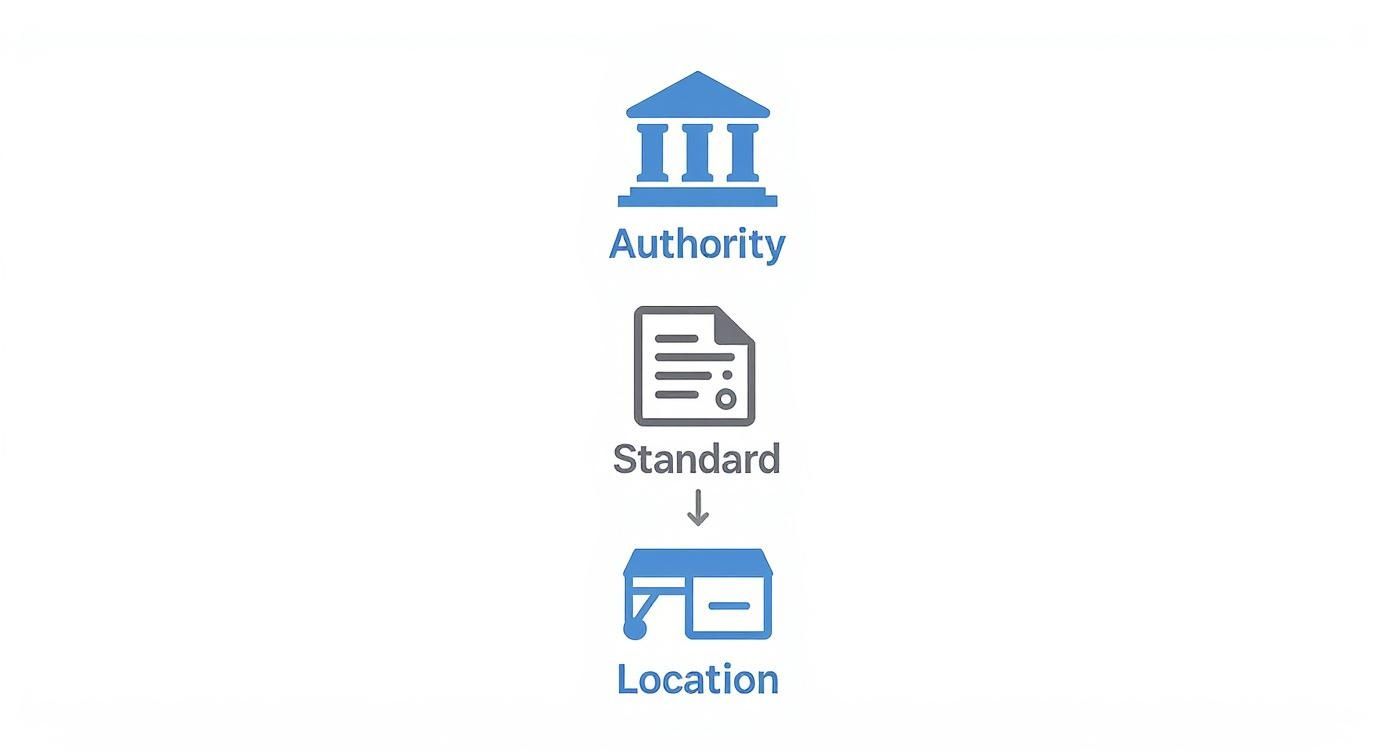
This hierarchy of protection is a perfect example of how electrical codes and standards translate from paper to the real world, flowing from the highest authority down to a specific piece of equipment.
This visual just hammers it home: safety rules start with a governing body (like the NEC), get baked into a standard (like UL 943), and are then applied right where they're needed, like that outlet in your kitchen.
The Challenge of Nuisance Tripping
One of the biggest headaches in this field is nuisance tripping. This is when a protective device trips out during perfectly normal operation, not because of a real hazard. It's a constant battle, especially in plants filled with equipment like variable frequency drives (VFDs) or servo amplifiers, which generate a ton of electrical "noise" that can fool a sensitive GFCI into thinking there's a problem.
Tempting as it may be, you can't just disable the protection. Instead, good engineers use a mix of strategies:
Use GFPE Devices: These equipment protectors are less sensitive than their personnel-protecting cousins (GFCIs) and often have adjustable time delays, letting them ignore momentary current blips.
Proper Shielding and Grounding: Simply making sure motor cables and control wiring are correctly shielded and grounded can slash electrical noise and solve a lot of problems.
Isolation Transformers: For really sensitive gear, an isolation transformer can create a clean, dedicated power source, completely separating it from the noise on the main system.
Wrestling these issues requires a deep, hands-on understanding of both the equipment and the electrical environment it lives in.
Selective coordination is the art of making sure the breaker closest to a problem opens first. It’s what stops a small, localized issue from turning into a full-blown, plant-wide outage.
Achieving Selective Coordination
Picture this: a small fault happens in one machine out on the factory floor. In a poorly designed system, that tiny hiccup could trip the main breaker for the entire building, bringing everything to a screeching halt. That’s exactly what selective coordination is designed to prevent. It’s an absolutely critical concept for building a reliable ground fault protection system.
The idea is to create a clear pecking order. The device right next to the fault—say, a small branch-circuit breaker—should trip first and fastest. The next breaker upstream, maybe for a larger feeder, is set with a slightly longer time delay. The main breaker? It has the longest delay of all. This tiered system guarantees that only the affected part of the circuit goes offline.
Pulling this off takes careful engineering and a lot of math to get the trip settings of every device just right. But when it's done correctly, you get the best of both worlds: enhanced safety and maximum uptime. For anyone diving into this process, getting a solid grasp of industrial control panel design is invaluable, as it shows you exactly how these protection schemes are woven into the heart of a control system.
The Long Road to Modern Electrical Safety
That little GFCI outlet in your kitchen, the one with the "TEST" and "RESET" buttons, is the result of more than a century of hard-won innovation. The idea of ground fault protection wasn’t a single brilliant idea that appeared overnight. Instead, it was painstakingly built, piece by piece, by engineers grappling with the new and often deadly challenges of a world powered by electricity.
To really get a feel for how far we've come, you have to go back to the turn of the 20th century. As power grids began stretching across the country, engineers ran into a huge problem: how do you shut down one faulty power line without plunging an entire city into darkness? The first attempts were clumsy, often just simple fuses that couldn't tell the difference between a momentary overload and a catastrophic fault.
The First Breakthroughs in Protective Relays
The first real leaps forward happened out of necessity, driven by the need to protect the massive new power plants of the era. One of the earliest game-changing moments was around 1899 at the Niagara power plants. Engineers there devised a clever way to achieve selective line protection for their 11 kV network, using a directional element to create a reverse current protection scheme. Many see this as the true birth of selective protection, a concept that's still at the heart of electrical safety today. You can dive deeper into the history of protection engineering and how these ideas came to be.
Right on the heels of that innovation came another critical development. In 1908, an engineer named Nicholson came up with the summation current circuit for detecting earth faults. It was a brilliantly simple concept: measure the current going out and compare it to the current coming back. If they don't match, you have a leak. This fundamental principle is still the basis for every GFCI and ground fault relay in use today.
The core idea behind modern ground fault protection is over 100 years old. It's based on a simple principle: what goes out must come back. If it doesn't, the electricity has leaked somewhere it shouldn't, and the circuit must be shut down instantly.
From Protecting the Grid to Protecting People
For decades, this kind of technology was strictly the domain of big utilities and massive industrial sites. The relays were huge, clunky mechanical devices—far too complex and expensive for the average home. The focus finally shifted toward personal safety in the 1950s and 60s, as a growing number of electrocutions were linked to faulty consumer appliances.
This is when engineers started playing with solid-state electronics to shrink the technology down and make it affordable. Professor Charles Dalziel of UC Berkeley, a pioneer in understanding how electricity affects the human body, was a key figure here. He developed a transistorized relay that would become the prototype for the modern Ground-Fault Circuit Interrupter (GFCI).
His work was the final piece of the puzzle. It proved you could build a device sensitive enough to detect the tiny, lethal currents that can stop a human heart, yet tough enough for daily use in a home. That breakthrough opened the door for the NEC to start requiring GFCIs in kitchens, bathrooms, and outdoor areas—a change that has saved countless lives and fundamentally reshaped our relationship with electricity.
Testing and Troubleshooting Your Protection System
A ground fault protection device is a lot like a silent guardian; you really only know it’s working when it suddenly springs into action. But how can you be sure it will actually do its job when the time comes? The only way is through regular, methodical testing and having a clear game plan for when things go wrong.
Putting a protection system in place is just the first step. The real work—verification, commissioning, and routine maintenance—is what turns a piece of hardware into a safety shield you can actually rely on. These procedures aren't just best practices; they're non-negotiable for keeping your electrical environment safe and running.
Essential Testing Procedures for Every System
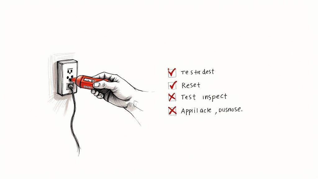
Making sure your ground fault protection is ready to go is a simple but vital habit. For the GFCIs in your home or office, it's a quick monthly check.
Push the Button: Press the "TEST" button on the GFCI outlet or breaker. You should hear a solid click as it cuts the power.
Double-Check: Plug in a lamp or phone charger to make sure the outlet is truly dead. No light, no power.
Bring it Back: Press the "RESET" button. The power should pop back on, and your test device should light up again.
For bigger industrial systems with ground-fault relays, the process is a bit more involved and is usually part of a scheduled maintenance program. This often means bringing in specialized gear to inject a simulated fault current, making sure the relay logic and breaker trip mechanisms work exactly as they were designed.
An untested protection device is just a hopeful assumption. Regular verification turns that assumption into a documented certainty, ensuring your safety net is ready to perform when a real fault occurs.
Diagnosing and Solving Nuisance Tripping
One of the biggest headaches you'll run into is nuisance tripping—when a GFCI or relay trips for no obvious reason. This can bring work to a screeching halt and make you lose faith in your system. The trick is to systematically hunt down the root cause instead of just mashing the reset button and hoping for the best.
Troubleshooting Steps for Nuisance Tripping:
Step 1: Isolate the Circuit: Unplug everything. If the GFCI resets and holds, you know the problem is with one of your devices, not the wiring itself.
Step 2: Find the Culprit: Start plugging things back in, one by one. The device that makes it trip is your source. Old motors, failing heating elements, or even a little moisture in an appliance can create tiny current leaks that a sensitive GFCI will pick up on.
Step 3: Inspect the Wiring: If the GFCI trips with nothing plugged in, the problem is likely in the wiring. Look for moisture in an outdoor junction box, worn-out insulation, or even a loose connection.
In industrial settings, things like servo amplifiers can generate enough electrical noise to cause nuisance trips, leading to jerky motor behavior or sudden shutdowns. In these cases, checking for properly shielded cables and a solid single-point grounding scheme often solves the problem without sacrificing safety.
Remember, a persistent trip isn't an annoyance—it's a signal that something needs a closer look.
Common Questions About Ground Fault Protection
Even with a solid understanding of the basics, a few common questions always seem to pop up when we're talking about ground fault protection. Let's tackle them head-on, because getting these details right is what makes these systems work in the real world.
What’s the Difference Between a Circuit Breaker and a GFCI?
Think of it this way: a standard circuit breaker is like a security guard for your building’s electrical system. Its job is to watch for huge problems, like a massive overload or a dead short, that could cause a fire. When it sees way too much current trying to flow, it shuts everything down.
A GFCI, on the other hand, is a personal bodyguard for you. It’s not looking for system-wide overloads. Instead, it’s watching for tiny, almost undetectable leaks of electricity—the kind that happen when current finds a path through a person. If it senses an imbalance as small as 4-6 milliamperes, it knows something is wrong and cuts the power in an instant.
Why Does My GFCI Outlet Keep Tripping?
We hear this one all the time. It’s often called "nuisance tripping," but it’s rarely a nuisance for no reason. The culprit can be something as simple as moisture getting inside an outdoor outlet box or even just a bit of accumulated dust creating a path for current.
Older appliances, especially those with motors or heating elements, can also develop tiny, harmless current leaks that are still just enough to make a sensitive GFCI do its job.
If you're trying to figure it out, here’s a quick process of elimination:
First, unplug everything from the GFCI circuit and hit the reset button.
If it stays on, start plugging your devices back in, one by one. When it trips, you’ve found the problem appliance.
If it trips immediately with nothing plugged in, the issue is likely in the wiring or the GFCI outlet itself. That's a job for a professional.
A GFCI that keeps tripping isn't just being annoying; it's sending you a signal. It's telling you there's a potential problem that needs attention, whether it's in a faulty appliance or the circuit itself.
Can I Install a GFCI on a Circuit Without a Ground Wire?
Yes, you can, and it's a common safety upgrade recognized by the National Electrical Code for older homes with two-wire circuits. A GFCI works by constantly monitoring the balance between the hot and neutral wires. If there's a difference, it trips—a function that doesn't need a ground wire to work.
There's a catch, though. You are required to label the outlet with a sticker that clearly says "No Equipment Ground" and "GFCI Protected." This lets everyone know that while the outlet offers excellent shock protection, it can't provide the grounding path that some electronics rely on for things like surge protection.
At E & I Sales, we live and breathe this stuff. We specialize in designing and building reliable, code-compliant UL-listed control panels that have exactly the right ground fault protection for your equipment and personnel. If you want to make sure your systems are both safe and efficient, contact us today.
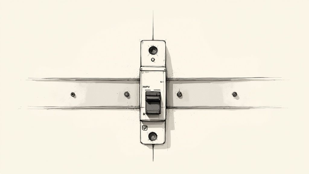
When you need to protect an electrical circuit, you might think of a fuse. But what if you could have a smarter, reusable fuse? That's essentially what a miniature circuit breaker, or MCB, is. It’s an automatic switch built to shield electrical circuits from the damage that excess current can cause.
Instead of blowing and needing a replacement, an MCB simply trips—shutting off the power. Once you've sorted out the underlying problem, you just flip it back on.
What a Miniature Circuit Breaker Really Does
At its heart, an MCB is the unsung hero in your electrical system. Whether it's tucked inside a complex UL control panel or on a manufacturing line, this little device is your first line of defense. Its job is simple but critical: watch the current flowing through a circuit and cut the power the second it detects danger.
Getting to grips with miniature circuit breakers is non-negotiable for real electrical safety. Without them, a minor wiring mistake or a failing motor could spiral into catastrophic equipment failure, a fire, or worse, a serious injury.
The MCB's Role in Industrial Control Panels
In the world of industrial controls, the stakes are even higher. These panels are packed with sensitive, high-value components like PLCs, VFDs, and motors that are incredibly vulnerable to electrical hiccups. This is where an MCB truly proves its worth.
To get a clearer picture of what an MCB is actually doing inside a control panel, let's break down its core protective duties.
MCB Core Functions at a Glance
Protective Function
Description
Typical Scenario
Overload Protection
Trips when a circuit draws slightly too much current over a period of time. This is a slow-acting response.
A conveyor belt motor is struggling under a heavy load, causing it to pull more amps than it's rated for.
Short-Circuit Protection
Trips almost instantly when it detects a massive, sudden surge of current, interrupting power in milliseconds.
A frayed wire makes contact with a metal enclosure, creating a direct path for current to flow to the ground.
Selective Coordination
Ensures only the breaker closest to a fault trips, isolating the issue without killing power to the entire system.
An issue with a single sensor's power supply trips its dedicated MCB, but the main panel breaker stays on.
These functions ensure that a localized problem doesn't cascade into a full-system shutdown, saving immense amounts of time and money in a production environment.
The growing reliance on these devices is clear in the market trends. The global miniature circuit breaker market has already ballooned past USD 5.7 billion. Industry analysis projects that number to more than double, hitting around USD 14.4 billion by 2034, all thanks to the increasing demand for dependable circuit protection.
An MCB is far more than a simple on/off switch; it’s a precision-engineered safety instrument. Its real magic lies in its ability to tell the difference between a harmless inrush of current—like a motor kicking on—and a genuinely dangerous fault. That intelligence is what makes it indispensable.
This guide is for the industrial buyers, panel builders, and engineers who need to go beyond the basics. We're going to dive into how they work, how to read their ratings and trip curves, and most importantly, how to choose the right one for your application to maximize both safety and uptime.
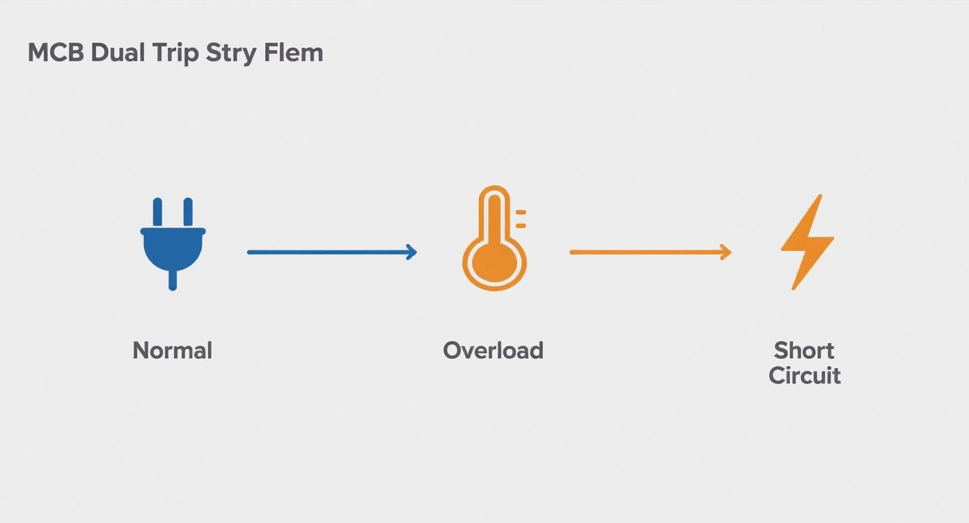
How an MCB Protects Your Circuits
On the outside, a miniature circuit breaker looks like a simple on/off switch. But tucked away inside that compact housing is a clever, two-part safety system built to stop two very different kinds of electrical threats: slow-building overloads and lightning-fast short circuits. This dual-action approach is what makes the MCB such a reliable defender of sensitive industrial equipment.
Think of it like having two security guards on duty. One is patient, always watching for trouble that builds up over time. The other is a hyper-alert sentry, ready to jump into action in a split second. Together, they ensure your circuits are protected from the full range of common electrical faults.
These two jobs are handled by two distinct but linked components: a thermal element and a magnetic element. Let's break down how each one works to keep your systems safe and sound.
The Thermal Trip for Overload Protection
The first line of defense is the thermal trip mechanism, which is designed to handle overloads. An overload is what happens when a circuit is forced to carry more current than it's rated for over a period of time—it's not a dead short, but it's still dangerous. A classic example is a pump motor straining under a heavy load or simply too many machines plugged into one line.
The magic behind this mechanism is a surprisingly simple part: a bimetallic strip.
How It Works: This isn't just one piece of metal. It's two different metals fused together, each one expanding at a different rate when it gets hot. As current passes through the strip, it naturally generates some heat.
Detecting an Overload: When an overload occurs, the extra current makes the strip get much hotter than usual. Because one metal expands faster than the other, this heat forces the strip to bend.
Tripping the Breaker: If the overload doesn't stop, the strip will bend far enough to physically shove a trip lever. That lever unlatches the switch contacts, breaking the circuit and shutting off the power.
This whole process is deliberately slow. This design prevents nuisance trips from brief, harmless current spikes, like the inrush current when a large motor kicks on. It only reacts to sustained overcurrents that signal a real risk of overheating, which could damage equipment or even start a fire. This is our patient guard, taking its time to correctly identify a problem that develops over seconds or minutes.
The Magnetic Trip for Short Circuit Protection
While the thermal trip patiently handles slow-burn problems, the magnetic trip mechanism is all about raw speed. Its only job is to react instantly to the catastrophic danger of a short circuit. A short happens when a low-resistance path forms between conductors, causing current to spike to hundreds or even thousands of times its normal level in an instant.
This kind of emergency demands a response far faster than a warming bimetallic strip can offer. That’s where an electromagnet comes in.
A short circuit is an electrical emergency. The magnetic trip function of a miniature circuit breaker is designed to react in milliseconds—often less than 10 milliseconds—to disconnect power and prevent catastrophic damage, arc flashes, and fires.
Inside the MCB, a coil of wire acts as an electromagnet. During normal operation, its magnetic field is negligible. But the moment a short circuit occurs, the massive surge of current flowing through the coil generates a powerful magnetic field.
This magnetic force is strong enough to yank a small plunger or armature, which in turn strikes the trip lever with incredible speed. The contacts are forced apart, and the power is cut—all in the blink of an eye. This is our fast-acting sentry, whose immediate action is absolutely essential for protecting people and equipment from the violent energy of a short-circuit event.
By combining these two distinct yet complementary trip mechanisms, a single MCB provides comprehensive protection. It intelligently differentiates between a motor starting up, a dangerously overloaded circuit, and a critical short-circuit fault, applying the right level of protection at exactly the right time.
Decoding MCB Trip Curves for Industrial Loads
Picking the right miniature circuit breaker goes way beyond just matching the amperage to the load. The real secret to bulletproof protection lies in understanding its reaction time—what we in the industry call its trip curve. This single characteristic defines how quickly an MCB shuts down under different fault conditions, and it's absolutely critical in an industrial setting.
Think of a trip curve as the MCB's "personality." Some are hair-trigger sensitive, reacting to the smallest hiccup. Others are more patient, built to ignore the brief, massive current spikes that are just part of a normal day for heavy machinery. Get this choice wrong, and you're staring down one of two barrels: constant nuisance tripping that kills production, or far worse, a breaker that doesn't act fast enough, leading to catastrophic equipment failure.
This behavior all comes down to the dual-trip system inside every MCB. A thermal element handles the slow-burn overloads, while a magnetic element reacts in a flash to dangerous short circuits.
The trip curve is all about tuning the sensitivity of that magnetic response. Let's break down the common types you'll find in the field.
Type B: The Sensitive Protector
A Type B MCB is the quickest on the draw. It’s designed to trip magnetically the moment the current hits 3 to 5 times its normal rating. This lightning-fast response is perfect for protecting purely resistive loads or circuits where you expect virtually no startup surge.
Best For: Heating elements, standard lighting circuits, and sensitive electronics that don't have big, beefy power supplies.
Industrial Scenario: A Type B is the perfect choice for the control wiring going to a PLC or for a small heating coil in a process machine. It gives you immediate protection without having to worry about a big inrush current.
But try to use a Type B on a motor, and you’re just asking for headaches. The motor's normal startup kick would blow right past that low magnetic threshold, tripping the breaker every single time you turn it on.
Type C: The Industrial Workhorse
The Type C curve is what you'll find in the vast majority of industrial control panels, and for good reason. It’s engineered to trip magnetically when the current spikes to 5 to 10 times its rating. That wider window gives it just enough breathing room to handle the normal inrush from most industrial loads without causing false alarms.
For general-purpose industrial use, the Type C curve strikes the perfect balance. It's tough enough to manage the startup demands of small-to-medium motors and inductive loads, yet it still provides rock-solid protection against true short-circuit faults.
Its versatility makes it the go-to for a huge range of equipment. This is a big plus for panel builders and maintenance crews because it simplifies stocking and specifying. We get into the nitty-gritty of sizing these correctly in our complete guide to the protection of motors.
Type D: The Heavy-Duty Specialist
When you're dealing with the real brutes of the industrial world—equipment with massive startup demands—you need a Type D MCB. This heavy-hitter is designed to hold on until the current reaches an incredible 10 to 20 times its rated amperage.
This high threshold allows it to completely ignore the huge, temporary current draw from large-scale industrial machinery firing up.
Best For: Large electric motors, transformers, industrial welders, and X-ray machines.
Industrial Scenario: Think about a giant conveyor system powered by a high-torque motor. It's going to pull an insane amount of current for a split second. A Type D breaker is built for exactly that, letting the motor start without a fuss while staying armed and ready for a genuine short circuit.
Matching the trip curve to your load’s electrical signature is the final, crucial step in specifying a reliable MCB. Get it right, and you ensure uptime by eliminating false trips while guaranteeing the device does its job when it counts.
Picking the Right MCB for Your UL Control Panel
Specifying a miniature circuit breaker for a UL 508A industrial control panel isn't just about grabbing something off the shelf that fits the DIN rail. It’s a job that demands precision. Every choice you make impacts the safety, compliance, and long-term reliability of the entire panel.
Think of it as the pre-flight checklist for your panel's electrical system. Get it right, and you've built a solid, safe foundation. Get it wrong, and you're setting yourself up for costly mistakes or, worse, dangerous failures down the line.
The first hurdle—and one of the most common trip-ups in panel design—is getting the UL standard right.
UL 489 vs. UL 1077: The Critical Distinction
These two UL standards look similar, but they define two very different jobs a circuit protector can do inside a panel. They are absolutely not interchangeable.
UL 489 Circuit Breakers: These are your heavy hitters, certified for branch circuit protection. A UL 489 breaker is built to be the first line of defense, capable of stopping the massive fault currents that can come from the main power feed. They’re required for protecting the main wiring and everything downstream.
UL 1077 Recognized Components: These are supplementary protectors. Think of a UL 1077 device as a specialist providing extra, more sensitive protection for a specific component, like a PLC or a power supply. It must be installed downstream of a primary UL 489 breaker.
Dropping a UL 1077 device into a spot where a UL 489 is required is a major code violation. It will instantly fail a UL inspection and, more importantly, it's a serious safety hazard. A supplementary protector simply isn't engineered to handle the raw energy of a major branch fault.
Calculating the Right Amperage Rating
Once you’ve locked in the correct UL listing, it's time to size the breaker’s amperage. This isn't as simple as matching the number on the nameplate of the load. The National Electrical Code (NEC) requires a built-in safety margin to prevent nuisance trips and overheating.
For most non-motor loads, the rule of thumb is to size the breaker for 125% of the continuous load current. For motors, things get a bit more complex, often starting at 250% of the motor's full-load amperes (FLA) and then adjusting for other factors. Nailing these load calculations is a cornerstone of good industrial control panel design and is non-negotiable for a safe system.
Don't Overlook the Short Circuit Current Rating (SCCR)
The Short Circuit Current Rating (SCCR) might be the single most important safety rating on an MCB. It tells you the maximum fault current the breaker can interrupt without literally blowing itself apart.
Your chosen MCB must have an SCCR that is equal to or greater than the available fault current at the point of installation. No exceptions.
Never install a miniature circuit breaker with an SCCR lower than the available fault current. Doing so creates a significant risk of an arc flash explosion, as the device could fail violently when attempting to clear a major short circuit.
Figuring this out is a system-level task. If you're not absolutely certain what the available fault current is, you need to have a qualified engineer perform a study to determine it.
This need for properly specified components is a global issue. As industrialization ramps up, especially in regions like Asia Pacific, the demand for reliable circuit protection has skyrocketed, making it the largest market for miniature circuit breakers. It’s a clear sign that modern electrical systems, no matter where they are, depend on getting these fundamental choices right.
MCB vs. Other Overcurrent Protection Devices
A miniature circuit breaker doesn't work in a vacuum. It's just one player on a much larger team of protective devices, and knowing where it fits is absolutely critical for designing a safe and reliable electrical system.
Each device has a very specific job to do. Mixing them up or assuming they're interchangeable is a recipe for disaster, leaving dangerous gaps in your system's safety net. To build a truly bulletproof panel, you need to understand how an MCB stacks up against the other common devices you'll find in any industrial facility. Let's break down the distinct roles of fuses, MCCBs, and RCDs/GFCIs so you're always grabbing the right tool for the job.
MCB vs. The Classic Fuse
For decades, the humble fuse was the king of overcurrent protection. It’s brilliantly simple: a small piece of wire engineered to melt and break the circuit when current gets too high. But that simplicity is also its greatest weakness.
Once a fuse blows, it's done. You have to replace it. That means stocking spares, dealing with downtime while someone hunts for the right one, and running the risk of an operator grabbing a fuse with the wrong rating just to get the machine back online.
This is where the miniature circuit breaker really shines:
It's Reusable: When an MCB trips, you just flip a switch to reset it. In a production environment where every minute counts, this is a massive advantage over digging through a parts drawer for a new fuse.
It's Smarter: A fuse just melts from heat. An MCB, on the other hand, has two distinct trip mechanisms working together—thermal for slow, creeping overloads and magnetic for sudden, dangerous short circuits.
It's Obvious: A quick glance at the panel tells you which circuit has tripped. No need for a multimeter to test a row of fuses.
While fuses definitely still have their place, especially in some high-rupture capacity applications, the MCB's convenience and superior, dual-action protection have made it the modern standard for branch circuits.
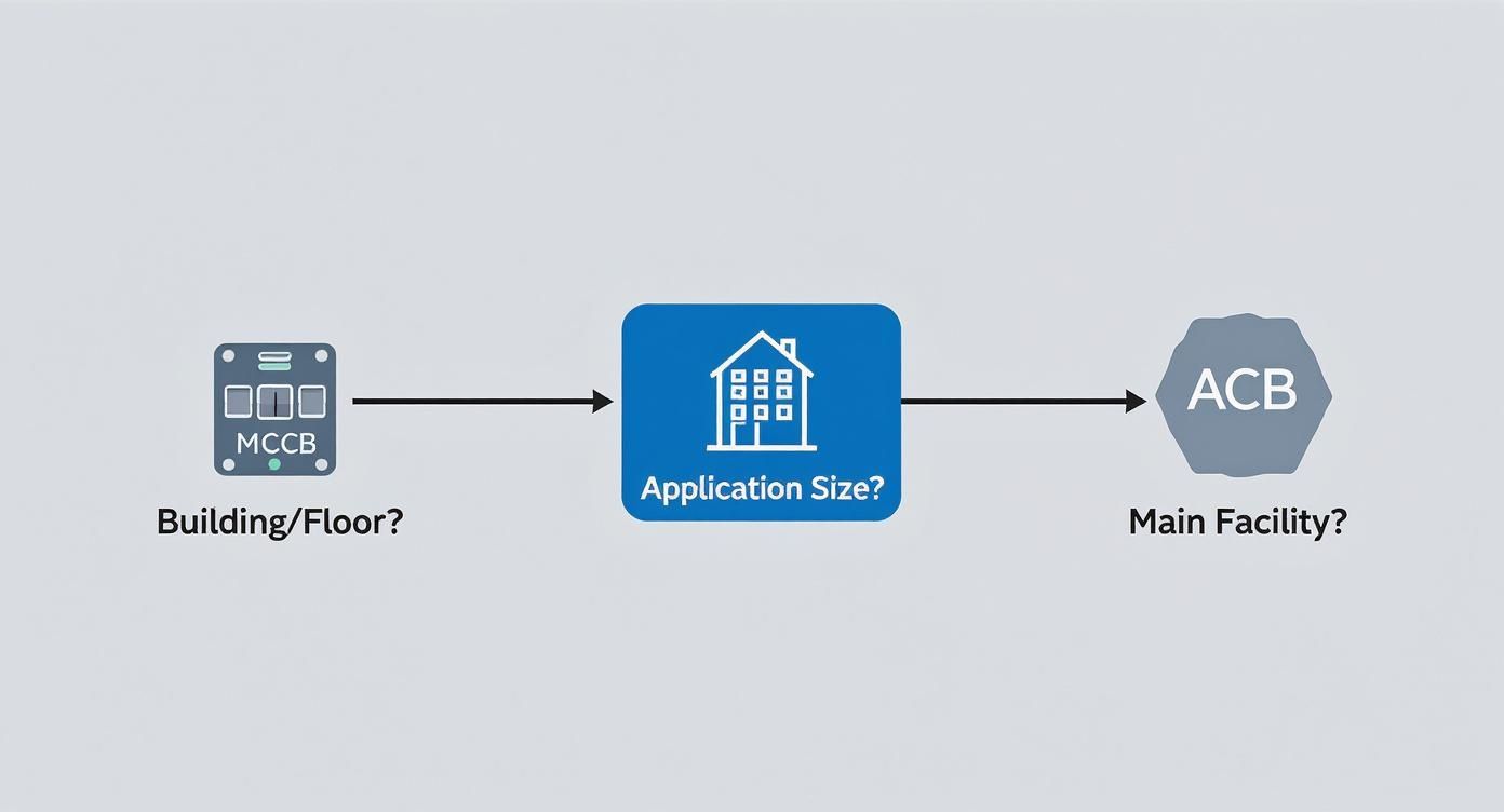
MCB vs. Molded Case Circuit Breaker (MCCB)
At first glance, an MCB and a Molded Case Circuit Breaker (MCCB) look like they do the same thing. They're both reusable breakers, right? Yes, but the difference is all about scale.
Think of it this way: an MCB is the security guard for a single office, while the MCCB is the security guard for the entire building lobby.
Your typical MCB is designed for lower-current applications, usually topping out at 125 amps. Its job is to protect the final branch circuits—the individual lines feeding a motor, a PLC, or a set of lights.
The MCCB is a completely different beast. It's a much beefier, more industrial device built for the heavy-lifting.
An MCCB is engineered to handle much higher currents, with ratings that can range from around 15 amps up to 2,500 amps. They are used to protect main feeders, distribution panels, and large-scale industrial equipment where the available fault current is significantly higher.
Another key difference is that many MCCBs have adjustable trip settings. This allows engineers to dial in the protection characteristics to precisely match the needs of a large motor or complex system. An MCB, by contrast, has fixed trip points set at the factory. If you're sizing protection for a main feed or a large piece of machinery, you should be looking at options like an ABB circuit breaker of the MCCB variety.
MCB vs. RCD and GFCI
Pay close attention to this one, because it's the difference between protecting equipment and protecting people. It's the most common and dangerous point of confusion.
An MCB is an overcurrent protection device. Period. Its entire purpose is to prevent fires and equipment damage when too much current flows.
A Residual Current Device (RCD), or its North American cousin, the Ground Fault Circuit Interrupter (GFCI), is a personnel protection device. It couldn't care less about overcurrent. Instead, it does something far more sensitive: it constantly measures the current flowing out on the hot wire and compares it to the current returning on the neutral.
If that difference is as tiny as 4-6 milliamperes, it knows that current must be leaking somewhere it shouldn't be—potentially through a person. It then trips the circuit in a fraction of a second, long before a fatal shock can occur. An MCB would be completely blind to a fault that small.
A truly safe system never forces you to choose. It uses both. The MCB protects the wires from melting, and the RCD/GFCI protects the operator from a lethal shock.
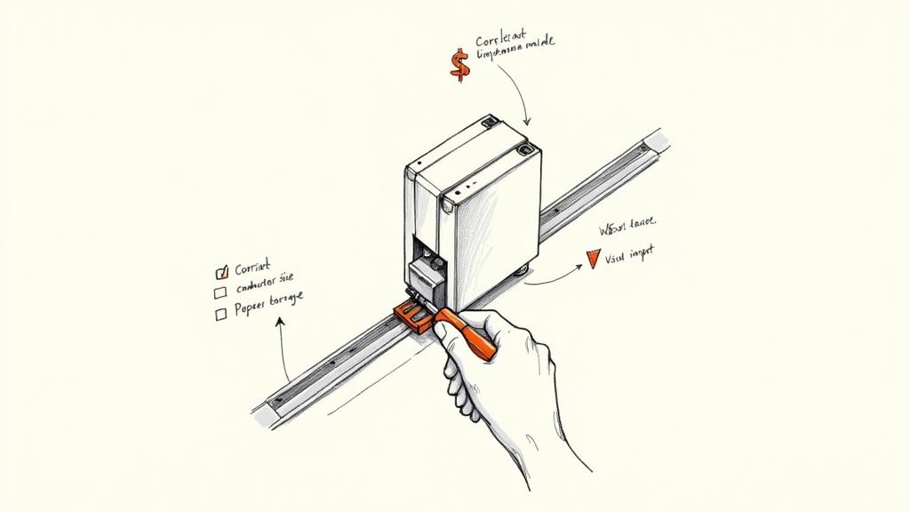
Getting Installation and Maintenance Right
A miniature circuit breaker is only as reliable as the hands that installed it. Getting the mounting, wiring, and routine checks right isn't just "best practice"—it's the only way to guarantee the device will do its job when it counts. Cut corners here, and you're setting the stage for overheating, premature failure, or worse.
This is where theory meets the real world. For the technicians and facility managers tasked with turning a box of components into a reliable, long-lasting asset, these practical steps are what truly matter.
Proper Installation Procedures
Solid installation is the foundation of electrical safety. Rushing these steps can create hidden problems that only show up during a fault condition—exactly when you need the protection to work. To build a rock-solid and safe connection from the start, focus on these key points.
Secure DIN Rail Mounting: Make sure the breaker snaps firmly onto the DIN rail. A loose MCB will vibrate, which can lead to iffy connections and wear out the terminals over time.
Use the Right Wire: Always match the wire gauge to the breaker's amp rating and what the load demands, following NEC guidelines. Undersized wires are a classic cause of overheating, creating the very fire hazard the MCB is there to prevent.
Get the Torque Right: This is one of the most critical and easily overlooked steps. Use a calibrated torque screwdriver to tighten the terminal screws to the manufacturer's exact spec. Over-tightening can crack the terminal, but under-tightening is just as bad—it creates a high-resistance hot spot.
Before energizing any system, running through a comprehensive electrical rough-in inspection checklist is a crucial final step. It’s your last chance to verify that every component is installed correctly and up to code.
A Simple, Effective Maintenance Schedule
Once it's in the panel, an MCB isn't a "set it and forget it" device. A little proactive maintenance turns a passive component into a verified safety asset. This simple schedule helps you spot trouble long before it becomes a critical failure.
A regular inspection routine is the cheapest insurance you can buy for system safety and longevity. Finding a loose connection early prevents major downtime and costly equipment damage down the road.
A basic but effective maintenance plan doesn't have to be complicated:
Quarterly Visual Checks: Just look for signs of trouble. Is there any discoloration or melting on the breaker's housing? That’s a dead giveaway for overheating. Check the wires connected to it for insulation that looks brittle or cracked—another symptom of too much heat.
Annual Terminal Check: During a planned shutdown, re-torque the terminal connections. Over months of operation, the normal heating and cooling cycles can cause screws to slowly loosen.
Annual Mechanical Test: While the power is off, just flip the MCB's switch on and off a few times. This simple action ensures the internal mechanism hasn't gotten stiff or seized, confirming it can physically trip when needed.
This straightforward approach to installation and maintenance will get the most life out of every MCB and, more importantly, reinforce the safety of your entire electrical system.
A Few Common Questions We Hear About MCBs
When you're in the weeds of a project, the practical questions always start to pop up. How you handle the small details around application, safety standards, and environmental conditions is what separates a reliable system from a problematic one.
We get these questions all the time from engineers and buyers in the field. Let's clear up a few of the most common points of confusion to make sure your electrical installations are safe, compliant, and built to last.
Can You Use a DC-Rated MCB on an AC Circuit?
This question comes up a lot, and the answer is a hard no. It's easy to think of a circuit breaker as just a simple switch, but the physics behind interrupting AC and DC power are worlds apart. The real challenge is snuffing out the electrical arc that forms when the contacts pull away from each other.
In an AC circuit, the current naturally drops to zero 120 times every second. This zero-crossing gives the breaker a built-in opportunity to kill the arc. DC current, on the other hand, is a constant flow with no zero-crossing point, which makes the arc incredibly stubborn and much harder to extinguish. Putting a DC breaker on an AC circuit (or vice versa) is a serious safety risk because the arc-quenching system just isn't designed for that type of current.
What's the Real Difference Between UL 489 and UL 1077?
If you're building control panels, this is a distinction you absolutely have to get right. These two UL standards define completely different roles for a protective device, and they are not interchangeable.
UL 489 Circuit Breakers: Think of these as the main line of defense. They are certified for branch circuit protection and are built tough enough to handle the massive fault currents that can come from a main power feed.
UL 1077 Supplementary Protectors: These are designed for more targeted protection within a piece of equipment. They sit downstream from a UL 489 device, offering more sensitive protection for specific components, but they simply don't have the muscle to interrupt a major branch fault.
How Does High Temperature Affect an MCB?
Heat is the natural enemy of an MCB’s thermal trip mechanism. Inside the breaker, a bimetallic strip is engineered to bend at a specific temperature generated by overcurrent, causing it to trip. When you install that breaker in a hot control panel or a high-ambient-temperature environment, that external heat gives the tripping process a head start.
This phenomenon is called thermal derating. It means the breaker will trip at a current well below its nameplate rating. To prevent frustrating nuisance trips, manufacturers provide derating curves that help you calculate the MCB's true operating capacity at elevated temperatures.
Should I Replace an MCB After a Major Fault?
Absolutely, yes. The safest and smartest move is to replace the breaker after it has interrupted a significant short-circuit. It might look perfectly fine on the outside and may even reset, but the violent forces at play during a major fault can cause serious, unseen internal damage.
A severe short circuit puts incredible stress on the internal components. It can weaken the contacts, damage the arc chute, or compromise the trip mechanism. Trusting a breaker that's been through that kind of event is a gamble you can't afford to take—it might not be there for you during the next fault.
An ABB circuit breaker is a whole lot more than just a switch. Think of it as the ever-vigilant guardian of your entire electrical system, a critical piece of hardware designed to protect your equipment, prevent disastrous downtime, and keep your people safe. It does this by instantly and automatically cutting the electrical flow the moment it detects an overcurrent or a short circuit.
Why Your Electrical System Depends on the Right Breaker
In any industrial plant or commercial building, your electrical infrastructure is the absolute bedrock of productivity. When it goes down, everything grinds to a halt. The circuit breaker is your first line of defense against electrical faults that can fry expensive machinery, spark fires, or trigger catastrophic system-wide failures.
This makes choosing the right one more than just a minor technical detail—it's a foundational business decision.
An inadequate or poorly chosen breaker is a ticking time bomb. It might fail to trip during a major fault, letting a destructive surge of energy rip through your system. On the flip side, it could be too sensitive and trip unnecessarily, causing those frustrating nuisance shutdowns that kill efficiency and waste man-hours.
The Real Cost of Electrical Downtime
The fallout from a system failure goes way beyond the immediate repair bill. For a manufacturing plant, just one hour of downtime can easily translate to tens of thousands of dollars in lost production. In a data center, it could mean wiping out critical services and information.
A properly specified ABB circuit breaker is designed to mitigate these exact risks by delivering reliable, predictable protection you can count on.
This need for reliability is a major reason for the sector's incredible growth. The global circuit breaker market, valued at a massive USD 25.2 billion in 2025, is projected to hit USD 57.5 billion by 2035, a surge driven by industrial expansion and infrastructure upgrades. You can dive deeper into this market growth on futuremarketinsights.com.
A Roadmap for Reliable Protection
Consider this guide your practical roadmap to understanding and selecting the perfect ABB circuit breaker for your application. We're going to cut through the complex jargon and focus on what really matters: real-world scenarios and actionable insights.
Think of circuit protection as an insurance policy for your electrical assets. A premium breaker like an ABB Tmax XT or Emax 2 doesn't just prevent damage; it preserves operational continuity and safeguards your bottom line.
Throughout this guide, we'll walk you through:
ABB's Core Families: We’ll break down the differences between Molded Case Circuit Breakers (MCCBs) like the workhorse Tmax XT and the powerful Air Circuit Breakers (ACBs) like the Emax 2.
Essential Specifications: You’ll learn how to read a technical data sheet like a pro and understand which ratings and specs are critical for your needs.
System Integration: Discover how these breakers connect with motor controls and panelboards to create a cohesive, safe, and fully integrated system.
Best Practices: We’ll cover the essentials of installation, maintenance, and system upgrades to guarantee long-term performance and reliability.
Navigating the ABB Circuit Breaker Portfolio
Diving into the world of ABB circuit breakers can feel like walking into a massive, highly specialized workshop. With rows upon rows of models and series, it's easy to feel a bit lost.
The secret? Don't try to memorize every part number. Instead, let's simplify the entire landscape by splitting it into two main categories. Each one serves a distinct, vital role in keeping an electrical system safe and running.
Think of it like building a fortress. You need guards patrolling the individual corridors and rooms, and you also need massive walls protecting the entire compound. Both are essential, but they operate on completely different scales.
Molded Case Circuit Breakers: The Guardians on Patrol
The first line of defense in any distribution system is the Molded Case Circuit Breaker (MCCB). These are the versatile workhorses, the guardians on patrol. You'll find them protecting individual circuits, feeders, and specific pieces of equipment.
ABB's Tmax XT series is a perfect example. These are the breakers standing guard over the motors, lighting panels, and machinery on a factory floor. They handle the everyday protection jobs, dealing with currents typically ranging from 15A up to around 3200A.
They get their name from their construction—all the critical components are housed inside a compact, sealed "molded case" made of a tough insulating material. This design makes them incredibly reliable.
What makes an ABB MCCB a go-to choice?
Compact Footprint: They are built to fit. Their smaller size is perfect for panelboards and switchboards where every inch of real estate counts.
Sealed for Reliability: The sealed case keeps dust, moisture, and prying fingers out. This ensures they work when you need them to, with almost no maintenance required.
Intelligent Protection: These aren't just simple on/off switches anymore. Many come equipped with sophisticated electronic trip units, like ABB's Ekip line, giving you precise, adjustable control over protection settings.
This blend of versatility and advanced protection is a big reason why ABB is a leader in the field. They've consistently developed circuit protection that meets the real-world needs of industrial facilities and commercial buildings. In fact, you can find more on ABB's market leadership at marketsandmarkets.com.
Air Circuit Breakers: The Fortress Walls
Now, let's zoom out. When you're not just protecting a single motor, but an entire facility—a hospital, a data center, a sprawling factory—you need the fortress walls. That’s the job of the Air Circuit Breaker (ACB).
ACBs, like ABB’s powerful Emax 2 series, are the heavy-duty protectors installed at the main service entrance. They are the first and last line of defense where power enters the building.
Built for massive currents, often from 800A up to 6300A and even higher, ACBs are fundamentally different from their molded-case cousins. They use the surrounding air to extinguish the enormous electrical arc that forms when interrupting a major fault. This requires them to be physically larger, more robust, and fully serviceable.
An ACB is your system's ultimate safety net. It’s engineered to handle the immense energy of a catastrophic short circuit right at the source, preventing a fault from cascading through your system and causing a complete shutdown.
What sets ACBs apart?
Massive Interrupting Capacity: They can safely stop fault currents that would vaporize smaller breakers, protecting the entire downstream network.
Built for the Long Haul: Their open construction is designed for maintenance. Key components can be inspected, serviced, and even replaced, giving them an incredibly long operational life.
More Than a Breaker: The Emax 2, for instance, is also a full-fledged power manager. It integrates measurement, protection, and communication features to help you monitor and optimize your facility's energy consumption.
To help you see the big picture, here’s a quick breakdown of how these families compare.
ABB Circuit Breaker Families at a Glance
This table offers a high-level comparison of ABB's primary circuit breaker series, highlighting where each one fits best. It's a great starting point for quickly identifying the right category for your needs.
Compact size, advanced electronic trip units (Ekip)
SACE Emax 2
ACB
Main service entrance, large industrial incomers, data centers
High interrupting capacity, power management functions
Formula
MCCB
Commercial and residential panels, smaller machinery (OEM)
Simplicity, reliability, and cost-effectiveness
SACE Isomax
MCCB (Legacy)
Older industrial installations and distribution panels
Robust, established performance (often subject to retrofit)
Ultimately, choosing between an MCCB and an ACB is the first and most critical step. Once you know which "fortress" component you need, you can drill down into the specific series and ratings.
Of course, getting the right hardware is only half the battle. Navigating the procurement channels is just as important. For that, it often helps to connect with electrical supply sales representatives who live and breathe this stuff every day.
How to Select the Perfect Breaker for Your Needs
Picking the right ABB circuit breaker is about more than just matching a few numbers on a spec sheet. It's about translating that technical jargon into a real-world understanding of how the device will protect your equipment, your facility, and your people. Let’s break down the specs that matter so you can make the right call, every time.
First up is a common point of confusion: the difference between Ampere Frame (AF) and Ampere Trip (AT). Think of it like this: the Ampere Frame is the physical size of the breaker, like the diameter of a water pipe. It sets the absolute maximum amount of current the hardware can handle.
The Ampere Trip, on the other hand, is the adjustable valve on that pipe. It's the specific setting that tells the breaker when to shut everything down. This is why you can have an ABB breaker with a 250A frame (the pipe) fitted with an interchangeable trip unit rated for 150A, 200A, or 225A (the valve). This gives you the flexibility to precisely match the breaker's protection to the load it's guarding.
Understanding Your System's Ultimate Safety Net
Beyond basic current ratings, the single most critical safety spec you'll encounter is the Interrupting Capacity, often labeled as kAIC (kiloampere interrupting capacity). This number tells you the maximum amount of fault current the breaker can stop cold without failing—or worse, exploding.
Imagine a dam holding back a river. The river's normal flow is your everyday operating current. A fault current is a flash flood—a violent, uncontrolled surge of energy. The interrupting capacity is that dam's ultimate strength rating. It absolutely must be strong enough to contain the worst-case flood.
A breaker's kAIC rating must be equal to or greater than the available fault current at its point of installation. Getting this wrong is one of the most dangerous mistakes in electrical design, creating a serious fire and safety hazard.
For example, a breaker sitting right next to a massive utility transformer might need a 65 kAIC rating or higher. Another one installed way downstream in a small sub-panel, where the potential fault current is much lower, might only need 25 kAIC. There's no room for guesswork here.
This diagram shows how the scale of your application—from a single floor's distribution panel to an entire facility's main switchgear—helps guide that initial choice between a molded-case (MCCB) or an air circuit breaker (ACB).
As you can see, the MCCB handles branch-level protection, while the heavy-duty ACB stands guard at the main service entrance. This visual makes that first big decision much clearer.
Choosing the Right Brains for the Operation
The final piece of the puzzle is the trip unit—the "brain" of the ABB circuit breaker. This is the component that actually senses an overload or short circuit and gives the command to trip. The two main types offer very different levels of control.
Thermal-Magnetic Trip Units: These are the reliable, workhorse standard. The "thermal" part uses a bimetallic strip that heats up and bends during a long, slow overload. The "magnetic" part reacts instantly to the huge current spike of a short circuit. They’re perfect for straightforward jobs like protecting lighting circuits or simple resistive loads.
Electronic Trip Units: When you get into industrial settings with motors and sensitive machinery, electronic trip units like ABB's Ekip series are in a league of their own. These are microprocessor-based brains that give you incredible control. You can fine-tune the trip settings for long-time (overload), short-time, and instantaneous (short-circuit) events. This precision is key for proper system coordination, ensuring the breaker closest to a fault opens first without taking down an entire production line.
For instance, you can program an electronic trip unit with a slight delay to ride through the normal inrush current of a large motor starting up. A basic thermal-magnetic unit might just see that as a fault and cause a nuisance trip. That's the kind of granular control that keeps a complex facility running smoothly.
Critical ABB Breaker Specifications Explained
This table provides a quick-reference guide to the essential ratings you'll find on any ABB breaker spec sheet and why they are so important.
Specification
What It Means
Why It Matters for Selection
Ampere Frame (AF)
The maximum continuous current the breaker's physical structure can carry.
Defines the breaker's physical size and ultimate current limit. You pick a frame that can house your required trip rating.
Ampere Trip (AT)
The current level where the breaker trips due to an overload.
This has to be matched to the load being protected (e.g., wire ampacity or motor full-load amps) to prevent damage.
Interrupting Capacity (kAIC)
The maximum fault current the breaker can safely interrupt without catastrophic failure.
This is a non-negotiable safety rating. It must be higher than the calculated available fault current where it's installed.
System Voltage
The nominal voltage of the electrical system (e.g., 480V, 600V).
The breaker's voltage rating must always be equal to or greater than the system voltage it's protecting.
By carefully evaluating these four key elements—frame size, trip rating, interrupting capacity, and trip unit technology—you can confidently choose an ABB circuit breaker that delivers the exact safety and performance your system demands.
Weaving Breakers Into Your Industrial Systems
An ABB circuit breaker doesn't work in isolation. You really unlock its value when it becomes a seamless, intelligent part of your larger electrical ecosystem. Think of it less like a standalone gadget and more like a key player on a team, constantly communicating and coordinating to keep your entire system robust, reliable, and safe.
This integration is absolutely crucial in two specific areas of any industrial facility: UL-listed panelboards and Motor Control Centers (MCCs). In these applications, the breaker isn't just a simple safety switch; it's a foundational building block that your operational continuity depends on.
Breakers in the Heart of the Operation: Motor Control Centers
Motor Control Centers are the central nervous system for a plant's machinery. They house the starters, drives, and protective gear for countless motors. The circuit breaker's job here is incredibly specific: protect very expensive motors from electrical faults without causing unnecessary downtime.
This is exactly where an advanced ABB circuit breaker with an electronic trip unit proves its worth. It gives you the granular control needed to tell the difference between a dangerous short circuit and the harmless (but high) inrush current you get when a big motor kicks on. This smart distinction prevents the kind of nuisance tripping that can grind production to a halt.
Here’s the bottom line: coordinated protection is everything. In a properly designed system, a fault on one motor circuit should only trip its dedicated breaker. This isolates the problem instantly, letting the rest of the facility run without missing a beat.
Getting Your System to Talk: Coordination and Communication
Modern industrial plants need more than just basic overcurrent protection; they demand data and communication. The latest ABB breakers come equipped with communication protocols like Modbus and Profibus, allowing them to "talk" directly to your central control system, whether it’s a PLC or SCADA.
This digital link completely changes the game, turning the breaker from a passive device into an active source of intel. It can report on:
Energy Consumption: Pinpoint exactly how much power individual machines are using to spot inefficiencies.
Operational Status: Get real-time feedback on whether the breaker is open, closed, or has tripped.
Fault Diagnostics: When a trip does happen, the breaker can tell you why—overload, short circuit, or ground fault. This slashes troubleshooting time for your maintenance crews.
This level of integration opens the door to predictive maintenance and much smarter energy management. By keeping an eye on a breaker’s performance data, your engineers can spot trends that might signal a developing problem with a motor long before it fails catastrophically.
This push for smart, interconnected electrical gear is a global trend. The Asia Pacific region, for instance, represents the largest piece of the pie, commanding about 45.7% of the total circuit breaker market revenue in 2024, largely driven by massive power grid projects in China and India. You can dig into more insights on the global circuit breaker market on mordorintelligence.com.
The Non-Negotiable: UL-Listed Assemblies
Finally, proper integration isn't just about clever features; it's about certified safety. When you install an ABB circuit breaker in a panelboard or switchboard, the entire finished assembly has to meet incredibly strict safety standards. A UL-listed assembly is your guarantee that the breaker, the enclosure, and all the internal wiring have been tested to work together safely as a single unit.
Mixing and matching components without that certification is a huge gamble. It can easily lead to overheating, bad connections, and a total failure to contain an electrical fault, creating serious fire and arc flash hazards.
For any system integrator or facility manager, specifying a fully tested and UL-listed assembly is simply non-negotiable. It ensures:
Code Compliance: Your system will meet national and local electrical codes, sailing through inspections without the headache of costly rework.
Verified Performance: The breaker's interrupting capacity and thermal limits are guaranteed to perform as expected within that specific enclosure.
Enhanced Safety: The assembly is proven to handle fault conditions safely, protecting both your people and your property.
By focusing on smart coordination, open communication, and certified assemblies, you can leverage the full power of an ABB circuit breaker and make it the cornerstone of a safe, efficient, and incredibly reliable industrial system.
Getting Installation and Maintenance Right
Here’s the thing about even the most advanced ABB circuit breaker: it's only as good as its installation and the care it receives afterward. Think of it like a high-performance race car engine. All that power is worthless without a flawless setup and regular tune-ups. Following best practices isn't just a recommendation; it's the only way to guarantee the long-term safety and performance of your entire electrical system.
This is about more than just ticking a box on a work order. It’s about actively fighting the two biggest enemies of any electrical gear: heat and neglect. A single loose connection or a bit of conductive dust is all it takes to spark a catastrophic failure, turning a critical asset into a dangerous liability.
Let's walk through a practical field guide for getting it right from day one.
Nailing the Installation the First Time
A breaker’s entire life story is written in the first few moments of its installation. When you rush this part, you introduce tiny, hidden weaknesses that might not show up for months or even years. When they do, it’s always a serious problem.
Pay close attention to three things: proper mounting, secure connections, and adequate clearance. Each one is non-negotiable for the breaker to do its job safely, both under normal load and during a fault.
Key Installation Steps:
Check Your Clearances: Make sure there's enough room around the breaker for air to circulate freely. Overheating is the number one killer of circuit breakers, and boxing it in without ventilation basically turns the enclosure into an oven.
Inspect for Damage: Before you even think about installing it, give the breaker a thorough once-over. Look for any cracks or defects in the case and terminals that might have happened during shipping. A compromised case means its structural and insulating properties are shot.
Torque to Spec. No Exceptions: This is the big one. Use a calibrated torque wrench and tighten every line and load connection to the exact manufacturer's spec. Too loose, and you create resistance and heat. Too tight, and you can crack the terminal and damage the breaker.
And of course, always follow the established safety standards. To make sure your work is fully compliant, you should always consult the relevant building codes and regulations.
Proactive Maintenance for Unshakeable Reliability
Once it's installed, an ABB circuit breaker isn't a "set it and forget it" device. A proactive maintenance schedule is your insurance policy against sudden failures and crippling downtime. While a well-cared-for breaker can last 30 to 40 years, that lifespan gets cut short fast in a harsh environment or without regular attention.
Maintenance is all about shifting your mindset from reactive (fixing things when they break) to predictive (spotting trouble before it starts). This means a smart mix of visual checks, mechanical tests, and more advanced diagnostics.
A well-maintained circuit breaker is a predictable asset. A neglected one is an unpredictable risk. Regular maintenance isn't a cost—it's an investment in operational stability and personnel safety.
Your maintenance plan needs to be built around your facility's unique conditions. Is it dusty? Damp? Full of vibration? For a deeper look at what that entails, especially for complex machinery, our guide to motor control center maintenance is a great resource.
Your Essential Maintenance Checklist
Here’s a practical, tiered approach for building out your maintenance schedule, starting with simple routine checks and moving to more involved annual tasks.
Annual Maintenance Tasks:
Infrared (IR) Scanning: Get an IR camera on the breaker while it’s under load. This is the fastest way to spot hot spots at terminals and connections before they can turn into a major failure.
Mechanical Testing: Manually switch the breaker on and off a few times. "Exercising" the mechanism like this ensures the internal lubricants don't gum up and seize.
A Thorough Cleaning: De-energize the system completely and use a vacuum (not compressed air, which just blows dust around) to clean out the breaker and its enclosure. This prevents electrical tracking and flashovers.
Connection Re-Torquing: Heat and vibration can cause connections to loosen slightly over time. After the initial settling-in period, it's smart to verify that all terminals are still torqued to the original spec.
Let's be honest—your facility's electrical system won't last forever. Components get old, technology marches on, and safety standards become more stringent. But what happens when your switchgear is showing its age, but a full, multi-million-dollar replacement just isn't in the budget? It’s a tough spot many facility managers find themselves in.
The good news? You don't always have to rip everything out and start from scratch. A smarter, more targeted approach is to upgrade the single most important component: the circuit breaker. This strategy, known as retrofitting, lets you infuse modern protection and intelligence into your existing gear.
By swapping out those old, tired breakers for a modern ABB model like the Tmax XT or Emax 2, you can give your entire system a new lease on life. You get the benefits of today's tech without the massive cost and downtime of a complete overhaul, stretching the reliable life of your switchgear for years.
Choosing Your Retrofit Strategy
When it's time to upgrade an older breaker, you've really got two main paths: a direct replacement or a full-on retrofit solution. Which one is right for you boils down to the age and model of your existing equipment.
Direct Replacement: This is the easiest route. For breakers from lines ABB recently acquired (like GE Industrial Solutions), you can often find a direct, form-fit replacement. A classic example is swapping an old GE Spectra breaker for a new Tmax XT with very little modification needed.
Retrofit Kits: For ancient or obsolete breakers from other manufacturers, a simple swap is off the table. This is where engineered retrofit kits are a lifesaver. These kits come with custom-designed hardware—think busbar adapters and mounting plates—that allow a modern ABB circuit breaker to be installed safely and securely inside an older switchgear cabinet.
Retrofitting isn't just a patch-up job; it's a strategic modernization. It lets you tackle the highest-risk parts of your system first, boosting safety and reliability in a big way while pushing massive capital spending further down the road.
Weighing the Costs and Benefits
The decision to retrofit or replace always comes down to a hard look at the costs and benefits. A full switchgear replacement is a massive capital project that almost always involves extended downtime—the kind that can bring production to a grinding halt.
A targeted breaker retrofit, on the other hand, is more like a surgical procedure. It can often be done in a fraction of the time, usually during a planned maintenance window, keeping operational disruptions to a minimum. While a high-tech breaker and a custom retrofit kit aren't cheap, the cost is almost always just a fraction of a full system replacement.
And just look at the tangible benefits you get:
Enhanced Safety: Modern breakers are simply better at what they do, offering far superior arc flash mitigation and more dependable fault interruption.
Improved Reliability: New components mean you're no longer gambling on old, worn-out mechanical parts. A well-cared-for breaker can last 30 to 40 years, and a retrofit essentially resets that clock.
Advanced Monitoring: When you upgrade to a breaker with an electronic trip unit, like an Emax 2, you suddenly unlock communication capabilities. That old switchgear can now feed you critical data on energy consumption and system health.
Simplified Maintenance: New breakers, especially the plug-in models, can slash maintenance time and effort by getting rid of the need to constantly re-torque connections.
Ultimately, retrofitting an ABB circuit breaker into your existing system is a powerful move. It delivers the most important safety and performance upgrades right where they count, buying you invaluable time and extending the life of your most critical electrical assets.
Got Questions About ABB Breakers? We've Got Answers.
Even after you've done your homework, a few specific questions always seem to pop up when it's time to choose, install, or upgrade an ABB circuit breaker. We get it. That's why we’ve put together some quick, straightforward answers to the questions we hear most often from engineers and facility managers out in the field.
Think of this as your go-to guide for getting clear on the details so you can make decisions with confidence.
What's the Real Difference Between an ABB MCCB and an ACB?
The biggest distinction boils down to three things: where it's used, how it's built, and how much power it can handle.
A Molded Case Circuit Breaker (MCCB), like ABB's workhorse Tmax XT series, is what you'll find protecting individual circuits, feeders, and motors all over a facility. They typically handle currents up to 3200A. Just like the name says, all its guts are sealed inside a compact, non-serviceable molded case.
On the other hand, an Air Circuit Breaker (ACB), like the beastly Emax 2, is the guardian at the gate. You'll find it at the main service entrance of a large facility, where it protects the entire building from a catastrophic fault. These are rated for massive currents, up to 6300A or even more. An ACB uses the surrounding air to extinguish the huge electrical arc when it trips and is designed with components that can be serviced, giving it a much longer operational life.
How Do I Pick the Right Trip Unit?
Choosing the right trip unit—the "brain" of the breaker—is absolutely crucial. It's what matches the protection to the exact piece of equipment it's supposed to be guarding.
Thermal-Magnetic Trip Units: These are the dependable, cost-effective standard for basic overload and short-circuit protection. They are the perfect fit for simpler, less critical loads like lighting panels or resistive heaters.
Electronic Trip Units: When you need precision and flexibility, you step up to an electronic unit like ABB’s Ekip series. These let you fine-tune everything—long-time, short-time, and instantaneous trip settings. This level of control is essential for protecting expensive motors and getting selective coordination right in a complex system.
Here's a simple rule of thumb: If you just need basic protection, thermal-magnetic will do the job. But if you're protecting motors, coordinating a multi-layered system, or you need advanced diagnostics and communication, an electronic trip unit is a must.
Can I Swap Out Another Brand's Breaker for an ABB Model?
This is a question we hear all the time, especially when dealing with older facilities. A direct, one-for-one physical swap is almost never possible because of differences in size and how they mount. But the answer is still usually yes—with a retrofit.
ABB has engineered retrofit solutions that come with custom adapter plates and busbar connections. These kits allow a modern, feature-rich ABB circuit breaker to be installed safely into an older switchgear cabinet that was built for a competitor's breaker that is now obsolete. It’s a smart way to bring your system's protection and reliability into the 21st century without the staggering cost and downtime of replacing the entire switchgear.
At E & I Sales, this is what we do day in and day out. Whether you’re just selecting a new breaker, planning a full-scale retrofit, or designing a complete UL-listed control panel from scratch, our team has the hands-on expertise to make sure you get a reliable, code-compliant solution that just works. Reach out and let's talk about your project at https://eandisales.com.
A truly proactive motor control center maintenance program is built on a foundation of rigorous safety prep, not last-minute fixes. It’s about creating a bulletproof plan before you ever open a cabinet—establishing clear Lockout/Tagout procedures, gearing up with the right arc flash PPE, and digging into the technical docs. This upfront work ensures every action you take is safe, informed, and actually effective.
Establishing Your MCC Maintenance Foundation
Before a single tool touches a motor control center, the real work has already begun. Laying the groundwork for safety and efficiency is everything. I’ve seen too many teams jump right in, and it's a dangerous mistake that leads to accidents, fried equipment, and painful stretches of downtime.
Effective maintenance isn't just about turning wrenches; it's about building a systematic, safety-first culture around these critical assets.
This foundation really comes down to three things: completely isolating energy sources, protecting your people, and knowing the equipment's history inside and out. If you drop the ball on any one of these, you're introducing massive risk and turning a controlled procedure into a high-stakes gamble.
Fortifying Safety with Lockout/Tagout Protocols
A rock-solid Lockout/Tagout (LOTO) procedure isn't just a suggestion—it's the absolute cornerstone of safe MCC maintenance. This is way more than just flipping a switch. It's a documented, verifiable process that guarantees all energy sources are dead and locked out before anyone gets started. For complex MCCs, that often means tracking down multiple power feeds, sneaky control circuits, and even the stored energy lurking in capacitors.
Your LOTO program has to be specific to each piece of gear. A generic, one-size-fits-all checklist just doesn't cut it. Here’s what a proper procedure looks like in the real world:
Detailed Shutdown Steps: It clearly maps out the sequence for de-energizing, isolating, and securing every single energy source. No ambiguity.
Verification of Isolation: This is the big one. A qualified person must test for the absence of voltage with a properly rated multimeter before work begins. It’s a non-negotiable step.
Clear Lock and Tag Application: It defines exactly who is authorized to apply locks and tags, making sure every worker involved has their own personal lock on the isolation point.
Shift Change Procedures: It lays out how LOTO is handed off between shifts to maintain a continuous bubble of safety.
The single most critical moment in any electrical maintenance task is proving the absence of voltage. Never, ever assume a circuit is dead. Always test, verify, and then test again before you proceed.
Selecting the Right Personal Protective Equipment
Personal Protective Equipment (PPE) is your last line of defense against the brutal physics of an arc flash. Let's be clear: standard work gloves and a hard hat are not going to cut it when you're working on or near an energized MCC. The level of PPE you need is determined by an arc flash risk assessment, which calculates the potential incident energy at that specific spot.
This risk is broken down into PPE Categories by NFPA 70E, ranging from 1 to 4. For instance, getting into a 480V MCC might call for Category 2 PPE. That typically means an arc-rated shirt and pants, an arc flash suit hood, and voltage-rated gloves with leather protectors. Always look for the arc flash label on the MCC panel—it will tell you the incident energy level and the required PPE category for working safely.
Gathering and Reviewing Essential Documentation
Walking into a maintenance job blind is a recipe for disaster. Before you even think about starting, your team needs to gather and review all the relevant documentation. This paperwork is your roadmap. It helps technicians understand the system's design, its operational history, and all its little quirks. If you're new to the equipment, just understanding what a motor control center is through some foundational reading can provide crucial context.
Here are the key documents you need in hand:
One-Line Diagrams: These show the power flow through the MCC, identifying sources, feeders, and major components.
Schematics and Wiring Diagrams: These give you the nitty-gritty details on control circuits, interlocks, and how everything is connected.
Previous Maintenance Logs: This is gold. It offers insights into past problems, repairs, and recurring issues that can help guide your inspection.
Reviewing this documentation lets you plan the scope of work, spot potential challenges ahead of time, and make sure you have the right spare parts and tools ready to go.
Your Proactive MCC Inspection Schedule
A reliable motor control center doesn't just happen. It's the direct result of a smart, consistent inspection schedule. If you're still stuck in the old "fix-it-when-it-breaks" loop, you're falling behind. In today's highly automated plants, unexpected downtime can easily eat up 20-30% of your production losses. That’s a massive, and frankly, unnecessary hit to the bottom line.
Building a rhythm of daily, monthly, and annual checks is the key. It transforms motor control center maintenance from a chaotic, reactive fire drill into a predictable, value-adding part of your operation. This is about catching the small stuff long before it has a chance to become a plant-stopping catastrophe. When everyone from floor operators to senior techs is involved, you create a culture of reliability.
This is the fundamental workflow for any maintenance task. It's a simple but powerful reminder: always review the documentation, put on the right gear, and properly isolate the equipment. Following this sequence every single time is non-negotiable for keeping your team safe and ensuring the job gets done right.
MCC Maintenance Schedule At a Glance
To make this easier to manage, here's a quick breakdown of what to focus on and when. This table summarizes the core tasks, helping you build a comprehensive plan that covers all your bases.
Frequency
Key Mechanical Checks
Key Electrical Checks
Key Safety Checks
Daily
Visual check for obstructions, loose parts, or physical damage.
Listen for unusual buzzing or humming. Check indicator lights.
Confirm area is clean, dry, and free of clutter.
Monthly
Verify cooling fan operation and check air filters for buildup.
Visually inspect terminal blocks for discoloration or heat.
Test pilot lights and annunciators. Ensure all labels are legible.
Annually
Torque all connections. Lubricate moving parts (stabs, breakers).
Perform thermal imaging, insulation, and contact resistance tests.
Verify grounding. Test breaker trip mechanisms and interlocks.
This schedule isn't just a checklist; it's a framework for consistency that drives long-term equipment health and operational stability.
The Power of Daily Walk-Throughs
The most frequent checks are often the simplest, but don't underestimate their power. These are quick sensory inspections that your plant operators can—and should—be doing on their regular rounds. We're not talking about a deep diagnostic analysis here; the goal is to spot anything that’s different from yesterday.
Train your operators to use their eyes, ears, and even nose to pick up on early warning signs. A faint, new buzzing sound or a slight discoloration on a panel might be the very first clue that something is starting to go wrong.
Here's what they should be looking for daily:
What You Hear: Listen for any unusual humming, buzzing, or crackling coming from transformers and contactors. A healthy MCC has a steady, low hum. Anything else needs a closer look.
What You See: Scan for any visual signs of overheating. This often looks like discoloration or darkened spots on enclosures, bus bars, or wire insulation.
What’s Around It: Make sure the area around the MCC is clean, dry, and completely clear of obstructions. Clutter can block critical airflow, leading to overheating, and it's a major safety hazard.
Monthly Hands-On Verifications
Monthly checks take things a step further than the daily walk-through. This is where a qualified technician gets a bit more hands-on. While these inspections are still mostly visual and non-intrusive, they focus on actively verifying the operational status of key components.
I remember one facility where a routine monthly check found a single, loose control wire on a critical starter. The constant vibration from nearby machinery was slowly working it free. It took less than five minutes to tighten that one connection. That simple fix prevented a plant-wide shutdown that would have cost the company tens of thousands of dollars for every hour they were down.
That’s the real value of proactive maintenance. You turn a potential catastrophe into a minor, two-minute adjustment. A few minutes of prevention truly saves days of cure.
On your monthly tour, zero in on these areas:
Pilot Lights and Indicators: Don't just look at them—manually test all pilot lights and indicator lamps to make sure they actually work. A burnt-out bulb could be hiding a serious fault.
Ventilation and Filters: Check that every cooling fan is spinning freely and that the filters are clean. Clogged filters are one of the top causes of overheating inside MCC cabinets.
Control Circuit Connections: Get a good look at the terminal blocks. You're looking for clean, tight wiring with zero evidence of heat damage or discoloration.
The Annual Deep-Dive Inspection
The annual inspection is the big one. This is the most intensive part of your motor control center maintenance program, where the equipment is fully de-energized, locked out, and given a complete, thorough service. Think of it as a comprehensive health check-up for your entire MCC.
This deep dive is your chance to uncover hidden problems that are impossible to spot during normal operation. It requires specialized test equipment and is absolutely critical for verifying the integrity of your whole electrical system.
Your annual checklist must include:
Thermal Imaging (Thermography): Before you shut anything down, perform a thermal scan of the MCC while it's under a normal load. This will instantly show you high-resistance connections and overloaded components by revealing hotspots invisible to the naked eye.
Insulation Resistance Testing: Grab a megohmmeter (or "Megger") and test the insulation resistance of the bus bars and all major cabling. This helps you find any degradation in the insulation before it can lead to a dangerous short circuit.
Contact Resistance Checks: For your circuit breakers and contactors, measure the resistance across the closed contacts. High resistance is a dead giveaway for pitting or wear and a clear sign that a failure is on the horizon.
Torque Verification: Break out a calibrated torque wrench and check every single electrical connection against the manufacturer's specifications. Loose connections are still the number one cause of electrical failures. Period.
With your inspection schedule locked in, it's time to get your hands dirty. This is where the real work of any solid motor control center maintenance program happens—moving from just looking at things to physically ensuring they're safe, reliable, and built to last.
This isn't just about going through the motions. How you handle these tasks separates a well-oiled MCC from a ticking time bomb. We'll break it down into four critical areas: mechanical cleaning, electrical connection integrity, protective device testing, and proper lubrication. Each one is a crucial piece of the puzzle.
Mechanical Cleaning for Optimal Performance
Don't underestimate dust and grime. In an MCC, they're not just ugly—they're a legitimate threat. A thick layer of industrial dust acts like a blanket, trapping heat and forcing components to run hot. This heat slowly cooks wire insulation and electronics, paving the way for an early failure.
Worse yet, if that dust has conductive particles (think metal shavings from a machine shop), it can create tiny bridges for electricity to cross, leading to a short circuit. Cleaning has to be done right.
Vacuum First: Start with a good vacuum that has a HEPA filter and non-conductive attachments. This gets rid of loose debris without just blowing it deeper into the equipment.
Use Approved Solvents: For the tough stuff, use a lint-free cloth and an approved, fast-drying electrical cleaning solvent. Never spray any liquid directly into the MCC.
Compressed Air with Caution: If you have to use compressed air, make sure it’s clean, dry, and free of oil. Use low pressure and aim the airflow to push contaminants out of the enclosure, not into sensitive spots like relays.
The Critical Art of Torquing Connections
Simply "tightening all connections" is a recipe for disaster. The goal is to torque all connections to manufacturer specifications. Overtightening is just as bad as a loose connection—it can stretch bolts, strip threads, and even warp bus bars, creating new hot spots.
You absolutely need a calibrated torque wrench for this. An uncalibrated one is just a fancy breaker bar, giving you a false sense of security. The whole point is to get the perfect clamping force for a solid, low-resistance connection that won't back off from heat cycles and vibration.
A shocking number of electrical failures boil down to one thing: a loose connection. Using a calibrated torque wrench isn’t just a nice-to-have; it's one of the most powerful preventative tasks you can perform.
Here’s a pro tip: After torquing, use a torque seal or paint marker to draw a line from the bolt head to the terminal. Next time you're in there, a quick glance will tell you if anything has vibrated loose. It's also a great idea to keep a log of the specified torque values for each section of your MCC.
Testing and Verifying Protective Devices
The circuit breakers, fuses, and overload relays are the silent bodyguards for your expensive motors. You can't just assume they're ready to do their job. These devices need to be tested to prove they will actually trip when a fault occurs. An overload relay that doesn't trip can turn a simple problem into a catastrophic motor burnout.
This requires specialized test equipment that can inject a controlled current to simulate an overcurrent or fault.
Primary Current Injection: This is the gold standard. The test set pushes a high current through the entire breaker or overload, testing every part of the system from the sensor to the trip mechanism.
Secondary Current Injection: This is a quicker, more common test. It checks the trip unit's "brain" and mechanics without sending high current through the main conductors. It's a fantastic way to verify the electronics are working correctly.
The results are compared against the manufacturer's time-current curve (TCC). If a device trips too slowly—or not at all—it’s no longer protecting your equipment and needs to be adjusted or replaced. Knowing the essentials of motor protection is key here, and you can dive deeper into the core principles of the protection of motors to build your team's skills.
Lubrication of Mechanical Systems
Finally, let's talk about the moving parts. Disconnect handles, racking mechanisms, and breaker stabs all need the right lubrication to work smoothly and safely. A handle that's seized up is a major safety hazard, especially in an emergency.
Stick to the manufacturer-recommended lubricant. The wrong grease can attract more dirt, attack plastic parts, or dry out and make the problem even worse. All you need is a thin, clean film of lubricant to cut down on friction without becoming a dust magnet. This simple step makes all the difference when you need to rack out a breaker or throw a disconnect in a hurry.
Using Predictive Technology to Prevent Failures
The best motor control center maintenance strategy is one that catches failures before they even think about happening. When you move past simple scheduled inspections, you start transforming MCC upkeep from a chore into an intelligent, data-driven process. This approach lets you put your time and resources exactly where they’re needed most, which is a massive win for cutting down unplanned downtime.
Predictive tools essentially give you x-ray vision into your equipment while it's running, uncovering threats you'd never see otherwise. Think of it as giving your MCC a high-tech check-up, spotting the small stuff when it's still small and easy to fix. This switch from reactive repairs to proactive intervention is a total game-changer for plant reliability.
Uncovering Hidden Hotspots with Thermal Imaging
One of the most powerful tools in your predictive toolkit has to be thermal imaging, or thermography. A thermal camera sees infrared energy, painting a picture of temperature differences. For an MCC, that's pure gold. It helps you instantly spot overloaded circuits, high-resistance connections, and failing components that are starting to run hot.
You just can't see these problems with the naked eye. I've seen it countless times: a routine thermal scan shows one breaker in a bucket running 15-20°C hotter than the identical units right next to it. That's an immediate red flag for a loose connection or a dying component, letting you schedule a quick fix during planned downtime instead of dealing with a catastrophic failure in the middle of a production run.
Listening for Trouble with Vibration Analysis
While thermal imaging is king for electrical issues, vibration analysis is your go-to for sniffing out mechanical problems in the motors themselves. Every motor has a specific vibration "signature" when it's running perfectly. Specialized sensors can pick up on tiny changes to that signature, giving you a heads-up on problems like:
Bearing Wear: This is the most common cause of motor failure, and it creates a very distinct high-frequency vibration.
Misalignment: When the motor shaft isn't perfectly lined up with its load, it causes serious vibration and stress.
Imbalance: Problems with rotors or connected fans can throw things off balance, leading to a ton of premature wear and tear.
Catching these things early means you're replacing a bearing for a few hundred bucks instead of a whole motor for tens of thousands. This is especially important for motors on complex drives; a good handle on variable frequency drive basics is crucial for figuring out if the problem is the motor or its controller.
Predictive maintenance isn't about replacing parts on a schedule; it's about replacing the right part at the right time. It's the difference between scheduled surgery and a trip to the emergency room.
Leveraging IoT for Continuous Monitoring
The next real frontier in MCC maintenance is integrating Internet of Things (IoT) sensors. Forget about doing periodic checks—IoT allows for continuous, real-time data collection on everything from temperature and current draw to voltage. This constant stream of information builds an incredibly accurate performance baseline for every single motor and starter.
This is where you see advanced strategies like predictive maintenance for MEP using IoT sensors really shine. The moment any reading strays from its normal baseline, the system can fire off an automatic alert to the maintenance team, pointing them to the exact component that needs attention.
This isn't just a trend; it's rapidly becoming the standard. In 2023, around 61% of newly installed MCCs came with IoT-enabled monitoring baked in. We saw the adoption of this tech jump by 48% between 2020 and 2023 alone. The data points to a clear industry shift toward smarter, more connected equipment that puts uptime first. By bringing these technologies into your facility, you're not just preventing failures—you're building a more resilient and efficient operation from the ground up.
Smart Documentation and Lifecycle Management
The best maintenance plan in the world doesn't mean much if the knowledge evaporates the second the job is done. Your real power comes from turning those maintenance actions into future intelligence. That's where meticulous records and a forward-thinking lifecycle plan come in. This documentation is your single most valuable tool for spotting wear trends, troubleshooting problems down the road, and proving you're meeting compliance standards.
Think about it: without a detailed history, you're flying blind with every new issue. Every inspection, every repair, every test, and every part swap needs to be logged with dates, technician notes, and specific measurements. This data trail becomes the living biography of your equipment.
Building Your Maintenance Logbook
Your maintenance log is so much more than a simple notebook; it’s a critical operational asset. It doesn't matter if it's a high-tech CMMS (Computerized Maintenance Management System) or a well-organized physical binder—consistency is what counts.
Vague entries like "checked starter" are completely useless. You need actionable detail. A solid log entry should always include:
Asset ID: The specific MCC and bucket number.
Date and Time: Exactly when the work was performed.
Technician(s) Involved: Who was on the job.
Description of Work: Be specific (e.g., "Performed annual torque check on main lugs and starter terminals").
Specific Findings: What did you find? Include real numbers (e.g., "L1 lug torqued to 275 in-lbs, L2 to 270 in-lbs, L3 to 275 in-lbs") or observations ("Found discoloration on overload relay contacts for motor P-101").
Parts Used: List any replacement components and their part numbers.
This level of detail is a goldmine. It allows you to analyze failure rates, track component aging, and predict when certain parts might need attention before they fail. It’s also a great way to spot knowledge gaps in your team, which is why it's so important to understand how to measure training effectiveness.
Strategic Spare Parts Management
Downtime is brutally expensive, but so is a warehouse crammed with spare parts you'll never use. The real goal is to build a smart, lean inventory based on your MCC's actual components and their known failure rates—all information you can pull directly from those detailed maintenance logs.
Don't fall into the trap of stocking one of everything. Focus your capital on the critical, long-lead-time components. Think specific overload relays, unique control transformers, or proprietary electronic modules. Standard fuses and contact kits can almost always be sourced more quickly when needed.
For instance, if your logs show that a particular model of contactor fails every three to four years across multiple buckets, it's a no-brainer to keep a few on the shelf. On the other hand, a main circuit breaker with a perfect track record probably doesn't warrant an expensive on-site spare.
Navigating Upgrades and Retrofits
Every MCC eventually hits a point where maintenance feels like a losing battle against obsolescence. When replacement parts get scarce or the equipment no longer meets modern safety standards like NFPA 70E, you have a choice: retrofit or replace.
A retrofit can be a great, cost-effective move. Upgrading old-school electromechanical overloads to modern electronic units can breathe new life, functionality, and reliability into an otherwise solid MCC structure. But if you’re dealing with a compromised bus bar system or a failing enclosure, a full replacement is often the safer and more economical long-term solution.
The decision really boils down to a clear cost-benefit analysis. You have to weigh the rising cost of maintenance and downtime for the old unit against the capital investment of a new one. This is especially relevant in a growing market. The global motor control center market was valued at USD 6.5 billion in 2024 and is projected to hit USD 10.2 billion by 2033, a surge driven by automation and the need for ever-more-reliable equipment. You can learn more about this trend and its impact on industrial operations at IMARC Group. Smart lifecycle management ensures you're investing wisely in this expanding field.
Your Top MCC Maintenance Questions, Answered
Even with the best-laid plans, questions always pop up when you're in the thick of maintaining a motor control center. It's just the nature of the beast. Facility managers and the techs on the floor often run into the same hurdles and have to make the same tough calls.
Let's clear the air on some of the most common questions we get from the field. These aren't textbook answers; they come from years of hands-on experience troubleshooting, maintaining, and upgrading these critical pieces of equipment.
How Often Should We Be Running Thermal Imaging on an MCC?
For most critical systems, annual thermal imaging is the gold standard. The key here is that the scan must be done while the MCC is energized and under a normal load. An unloaded MCC won't show you the thermal hotspots that indicate high-resistance connections, which defeats the whole purpose.
But don't treat that as a hard-and-fast rule. If your MCC lives in a rough neighborhood—think high ambient heat, tons of dust, or constant vibration—you'd be smart to bump that up to semi-annually. This gives you a much better chance of catching things like loose connections or overloaded circuits long before they turn into a catastrophic failure.
What Are the Most Common Points of Failure?
You might be surprised to learn that the biggest headaches in an MCC often start with the smallest parts. In our experience, a handful of specific components are behind the vast majority of failures.
Keep a close eye on these usual suspects:
Loose Terminal Connections: This is, hands down, the number one cause of overheating and electrical faults. It's almost always driven by vibration and the constant expansion and contraction from thermal cycling.
Control Component Failure: Relays and contactors are mechanical devices, and they wear out. All that constant cycling takes a toll on the coils and contacts.
Starter Coil Burnout: Whether it's from overvoltage, undervoltage, or just old age, starter coils eventually give up the ghost, taking the whole motor circuit down with them.
Insulation Degradation: Over the years, heat and environmental junk break down wire insulation, which is a ticking time bomb for short circuits.
The overwhelming majority of MCC faults trace back to a mechanical issue, not a purely electrical one. A loose wire, a worn contact, or a stuck relay is often the root cause—which is exactly why hands-on inspections and torque checks are so vital.
When Should We Retrofit vs. Replace an Entire MCC?
The "repair or replace" debate for an aging MCC usually boils down to a few key factors. If your unit is pushing 20-25 years old, just tracking down compatible spare parts can turn into a full-time, expensive scavenger hunt.
But age isn't the only factor. Watch out for these other red flags:
Rising Failure Rate: If your maintenance logs show a clear trend of more frequent failures and downtime, that unit is on its last legs.
Outdated Safety Standards: Older MCCs were built in a different era. Many simply can't meet modern arc flash safety requirements, and that puts your people at risk.
Exceeded Capacity: Your facility has grown, but has your MCC? If you're pushing its original design capacity, you're borrowing trouble. It's time for an upgrade.
Most of the time, a simple cost-benefit analysis makes the decision for you. When you compare the rising cost of emergency repairs and lost production against the investment in a new, safer, and more reliable system, the right path forward becomes pretty clear.
When it's time to upgrade, retrofit, or design a new system, having an expert partner makes all the difference. E & I Sales provides engineered UL-listed control panels and turnkey integration services to ensure your motor control solutions are reliable, safe, and built for the long haul. Let's discuss your next project.