At its core, a Power Distribution Center (PDC) is the nerve center of your plant's electrical system. It’s the single point where massive, high-voltage power from the utility grid gets tamed, organized, and sent out to every piece of equipment on your floor.
Think of it as the quarterback of your entire operation, taking the raw power and distributing it precisely where it needs to go, ensuring everything from giant motors to sensitive control panels gets a clean, reliable feed.
Decoding the Role of a Power Distribution Center
Let’s use an analogy. Imagine the power coming from the utility is like a raging river—incredibly powerful, but far too chaotic and dangerous to be useful. A PDC acts like a sophisticated dam and irrigation system. It takes that raw, high-voltage flow, safely steps it down, and channels it into a network of smaller, manageable circuits.
Each of those smaller streams is perfectly sized for the equipment it feeds. Without that control, you’d have an unmanageable and hazardous surge of energy. The PDC provides the essential structure, protection, and a single point of command for your facility’s entire electrical backbone.
The Core Mission of a PDC
When you strip everything else away, a PDC is all about safety and operational reliability. It’s a purpose-built fortress designed to protect your people, your multi-million-dollar assets, and your production schedule from catastrophic electrical failures.
It accomplishes this mission through a few critical jobs:
Voltage Transformation: It uses transformers to step down high utility voltage (like 13,800 volts) to a safe, usable plant voltage (typically 480 volts).
Circuit Protection: It’s packed with circuit breakers and fuses that act as sentinels. They instantly cut power during an overload or short circuit, preventing equipment damage and fires.
Centralized Control: By bringing all the main breakers and distribution points into one spot, it makes operations, maintenance, and emergency shutdowns straightforward and safe.
A well-engineered PDC is much more than a steel box full of wires. It's the foundation of your plant's uptime. It ensures a problem in one area doesn't trigger a domino effect, taking down the entire facility and costing you a fortune in lost production.
Beyond traditional fixed installations, it's also worth looking at how innovations in mobile energy solutions are changing the game for temporary or remote power needs.
The table below breaks down the essential functions of a PDC and why they matter in a real-world industrial setting.
Function
Core Purpose
Operational Benefit
Voltage Reduction
To step down high-voltage utility power to safe, usable levels for plant equipment.
Prevents equipment damage from over-voltage and ensures compatibility with standard machinery.
Power Distribution
To divide the main power feed into multiple smaller, dedicated circuits.
Allows for isolated control and protection of individual machines or operational areas.
Overcurrent Protection
To automatically interrupt power flow during short circuits or overload conditions.
Protects expensive assets from electrical damage and significantly reduces fire hazards.
Centralized Control
To consolidate main disconnects and controls into a single, accessible location.
Simplifies maintenance, speeds up troubleshooting, and makes emergency shutdowns fast and effective.
Fault Isolation
To contain electrical faults to a single circuit, preventing a plant-wide outage.
Maximizes operational uptime by ensuring a localized problem doesn't cascade across the facility.
Metering & Monitoring
To measure and record electrical usage, voltage, and current for the facility.
Provides critical data for energy management, load balancing, and predictive maintenance.
Each of these functions contributes to a more resilient, safe, and efficient operation.
Why Centralization Matters
The genius of the PDC lies in its centralized design. Instead of having a messy web of electrical panels scattered all over your plant, you get a single, organized source of truth for power management.
This makes life infinitely easier for your maintenance crews when they're troubleshooting an issue. It also makes critical safety protocols, like lock-out/tag-out procedures, simple and effective to implement. By consolidating all this hardware into one place—often a dedicated electrical house (e-house)—you build a tough, manageable, and secure power backbone for your entire plant.
Anatomy of a Power Distribution Center
To really get what a power distribution center does, you have to look past the heavy steel box and see the critical components working together inside. The best way to think of a PDC is as a highly specialized team, where every member plays a specific part in safely wrangling and delivering electricity. From the moment high-voltage power hits the enclosure, it starts a carefully controlled journey through a series of essential devices.
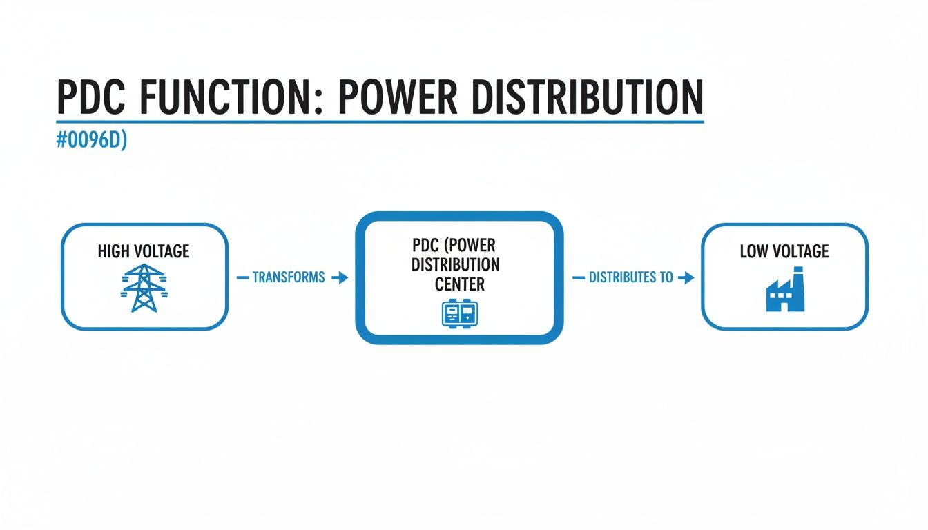
This entire flow is engineered to take raw, high-voltage utility power and tame it into a safe, reliable, and usable form for everything in your facility. The visual below really breaks down this core job, showing how the PDC acts as the vital link between the grid and your plant floor.
As the diagram shows, the PDC’s primary mission is simple but critical: take high-voltage power, step it down, and send it out as manageable low-voltage circuits ready for the real work.
The Main Incoming Section
The journey starts at the main incoming section. This is the single, secure gateway for all power entering the PDC. It’s where you’ll find the main circuit breaker or a fused switch, which acts as the master on/off switch for the whole system. This one point of control is absolutely essential for maintenance and emergencies, giving qualified people the ability to kill power to the entire center with one action.
This section is built like a fortress, engineered to handle the full force of the utility's available fault current. Its rugged design ensures it can withstand the incredible electrical forces of a short circuit, shielding all the downstream components from a catastrophic meltdown. Think of it as the main gatekeeper—controlling access and providing the first line of defense.
Transformers and The Main Bus
Once power is safely inside, its first stop is the transformer. You could argue this is the single most important component in the whole setup. Its job is to step down the high utility voltage—often 13.8 kV or even higher—to a usable plant voltage, like 480V. This transformation is what makes the electricity compatible with, and safe for, all your standard industrial motors and machines.
From the transformer, the now lower-voltage power flows to the main bus. This is the PDC’s superhighway. The main bus is a set of thick copper or aluminum bars that distribute power horizontally across the unit, feeding it to all the individual circuit breakers connected to your equipment.
The main bus is the central artery of your power distribution center. Its size and bracing are meticulously engineered to handle the total electrical load of your facility and withstand the powerful magnetic forces generated during a fault condition.
Circuit Breakers: The Guardians of Your Equipment
Branching off that main bus, you'll find the individual circuit breakers. These are the vigilant guardians protecting your expensive assets. Each breaker is sized for a specific circuit, constantly monitoring the current flowing to a motor, a production line, or a control panel. If it senses an overload or a short circuit, it trips automatically, instantly cutting off the power.
You’ll typically see a few common types of breakers inside a PDC:
Molded Case Circuit Breakers (MCCBs): These are the workhorses for most branch circuits. They provide reliable, compact protection for loads usually under 1,200 amps.
Insulated Case Circuit Breakers (ICCBs): A step up from MCCBs, these offer higher interrupting ratings and more advanced trip units, making them a great middle ground for more critical loads.
Air Circuit Breakers (ACBs): Found on main disconnects and large feeder circuits, these are heavy-duty, often withdrawable devices built for high currents and the toughest industrial settings.
Getting the selection and coordination of these breakers right is non-negotiable. A properly designed system ensures that a fault on one small motor trips only its dedicated breaker, instead of causing a domino effect that shuts down an entire section of the plant. This strategic isolation is the secret to maintaining uptime and the hallmark of a well-engineered power distribution center.
Navigating Safety with UL Listings and Electrical Codes
In the high-stakes world of industrial power, safety isn’t a guideline—it's everything. When you're managing the kind of energy that flows through a power distribution center, there’s simply no room for error. This is exactly why third-party certifications and standardized electrical codes aren't just red tape; they are your most trusted partners in keeping people and equipment safe.
Think of these standards as a library of lessons learned the hard way, built from decades of real-world experience. Following them isn’t about checking a box. It’s about laying the foundation for a reliable, compliant, and fundamentally safe electrical system.
The UL Mark: More Than Just a Sticker
When you see that little UL mark on a power distribution center, it’s a big deal. It’s a public declaration that the entire piece of equipment has been pushed to its limits in a series of grueling safety tests by Underwriters Laboratories (UL), a name respected around the globe.
A UL-listed assembly, like a switchboard built to the UL 891 standard, has been tested as a complete, integrated system. This is a critical point. It confirms that all the individual parts—the breakers, the bus bars, the wiring—don't just meet their own standards but can work together safely under the immense stress of a full load or a fault condition.
That holistic certification gives you genuine peace of mind, knowing the PDC has been engineered to prevent foreseeable risks of fire, electric shock, and other hazards. It’s a crucial difference, and knowing the details matters. You can dig deeper into why a fully listed assembly is so vital for your project by understanding the difference between a UL Listed vs UL Recognized panels.
Playing by the Rules: The National Electrical Code
While UL confirms the equipment itself is built safely, the National Electrical Code (NEC), or NFPA 70, dictates how to install it safely. The NEC is the gold standard for electrical design and installation in the U.S., and you can bet your local inspector knows it inside and out.
For PDCs, a few parts of the code are especially important:
Working Clearances (NEC 110.26): This isn't about giving technicians extra elbow room for comfort. It’s a strict requirement for unobstructed space around gear, ensuring they can do their job without being put in a dangerous, cramped position near live components.
Grounding and Bonding (NEC Article 250): You could argue this is the single most important safety feature in any electrical system. Proper grounding gives fault currents a safe, easy path to follow, which allows breakers to trip in a fraction of a second and keeps lethal voltage off the metal enclosures of your equipment.
Overcurrent Protection (NEC Article 240): This article lays out the rules for sizing and coordinating breakers. The goal is what’s called "selective coordination"—making sure that if a fault happens, the breaker closest to the problem is the only one that trips, isolating the issue without shutting down a whole section of your plant.
Nothing stops a project dead in its tracks faster than a failed electrical inspection. Partnering with a UL-certified panel shop that designs and builds to NEC standards from day one is the surest way to avoid expensive rework, infuriating delays, and the very real safety risks that come with non-compliance.
At the end of the day, UL listings and the NEC are two sides of the same safety coin. One proves the equipment is inherently safe. The other ensures it’s installed for a lifetime of safe operation. Together, they create the framework for a system that protects your people, your investment, and your peace of mind.
How to Size and Specify Your Power Distribution Center
Picking the right power distribution center isn't like grabbing a part off a shelf. It's a foundational engineering decision that dictates the safety, efficiency, and future of your entire operation. Getting it wrong leads to real consequences: dangerous under-protection, wasteful over-engineering, or a system that chokes the moment you try to expand.
You have to be methodical. The whole process kicks off with one simple but absolutely critical question: how much power do you actually need?
Calculating Your Total Electrical Load
First things first, you need to make a list. A really detailed list. I'm talking about every single piece of equipment that will pull power from this PDC. It's not just about the huge motors and conveyor systems; it’s the lighting panels, the HVAC units, the control cabinets—everything.
For each item, you need its full-load amperage (FLA) and voltage. And don't you dare forget about inrush current. Large motors can draw 5 to 8 times their normal running current for a split second on startup. If you only size for the running load, your main breaker will trip the moment a big motor kicks on.
Once you have your complete load list, you can add it all up. But let's be realistic—it's rare that every machine will be running at 100% capacity all at the same time. This is where demand factors, straight from the National Electrical Code (NEC), become your best friend. They help you size the system for how it will actually be used, saving a ton of money.
And whatever you do, plan for the future.
One of the most common and costly mistakes I see is sizing a power distribution center only for today's needs. A good rule of thumb is to add 20-25% additional capacity to your calculated load. This gives you room to grow without needing a massive, expensive overhaul in a few years.
Determining Voltage and Fault Current Ratings
With your load figured out, it's time to define the electrical environment your PDC will live in. You need to lock down the system voltage, which is usually set by what the utility provides and what your biggest machines need. Here in North America, 480V three-phase is the workhorse of industrial power.
Just as important is the available fault current. This is the absolute maximum amperage the grid can slam into your PDC during a dead short. It’s a scary number, and it’s one of the most critical safety metrics in your entire facility. You'll need an electrical engineer to perform a short-circuit study to get this value.
That number directly tells you what the Short Circuit Current Rating (SCCR) of your PDC needs to be. The SCCR is a measure of how well the gear can take a punch—its ability to withstand a massive fault without exploding or catching fire. The PDC's SCCR must be higher than the available fault current. There is zero room for negotiation on this. We dive deeper into all the factors that play into this in our guide on proper circuit breaker sizing.
Accounting for Environmental and Physical Constraints
Finally, you have to think about the real world. Where is this thing actually going to sit? The physical environment has a massive impact on the enclosure you choose and the components inside.
Ask yourself these questions:
Location: Is it going inside a clean, climate-controlled e-house? Or will it be sitting outdoors, getting blasted by rain, snow, and scorching sun? This will determine the NEMA rating you need (like a NEMA 3R for outdoor gear).
Atmosphere: Are you dealing with explosive gases or combustible dust? If it's a hazardous location, you're looking at specialized, explosion-proof enclosures and components.
Footprint: How much real estate do you have? If you're crammed into a tight spot, you might need a custom-engineered layout or a multi-section design to make it fit.
Working through these questions will tell you if a standard, off-the-shelf design will work or if you need to go custom. Standard PDCs are great and cost-effective for many jobs, but a custom unit gives you the flexibility to handle unique voltages, specific brands, or a really challenging footprint. This way, you end up with a PDC that's not just good enough, but perfectly matched to your operation.
Integrating Power Centers With Automation Systems
A modern power distribution center is so much more than a passive electrical box. It’s an active, intelligent nerve center for your entire facility's operational network. A truly effective PDC doesn’t just shuttle power around; it talks, giving you a real-time window into the health and performance of your whole electrical system.
This leap—from silent hardware to a communicative asset—is one of the biggest advancements we've seen in industrial power management. When you integrate your PDC with your plant-wide automation systems, you’re tearing down the old walls between power and control. What you get is a single, unified ecosystem.
From Isolated Power To Connected Intelligence
In the old days, the power system and the control system were two separate worlds. The PDC did its job, the automation system managed the processes, but they rarely spoke the same language. Frankly, that model is obsolete.
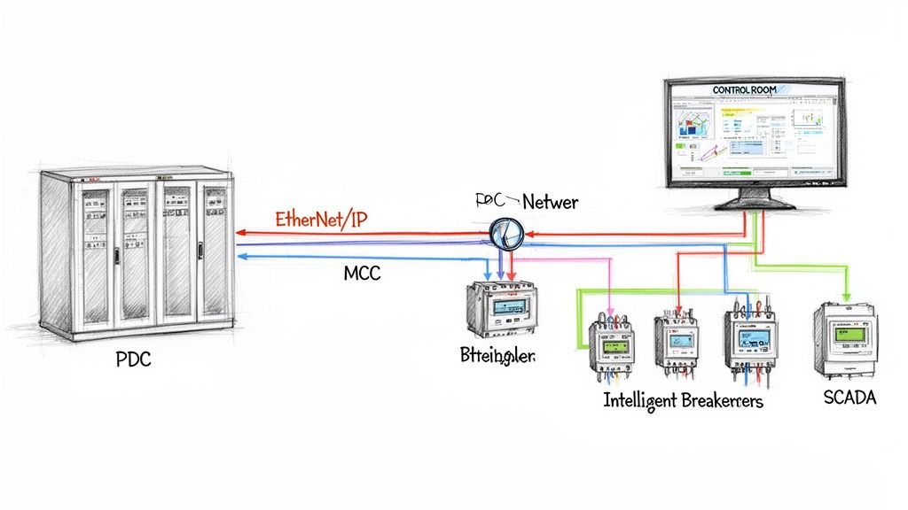
Intelligent devices are the bridge. Today’s circuit breakers, meters, and protective relays come equipped with communication capabilities right out of the box. Using standard industrial protocols like EtherNet/IP or Modbus TCP/IP, these devices feed a constant stream of valuable data from the PDC straight to your central control platform, whether that’s a Programmable Logic Controller (PLC) or a SCADA system.
This connectivity transforms the PDC from a simple electrical panel into a rich source of operational intelligence. It unlocks powerful new capabilities that were just a pipe dream with older, isolated setups.
What Integration Really Gets You
Hooking up your power and control systems isn't just a technical exercise; it delivers real, tangible benefits that hit your bottom line. The data flowing from your PDC provides deep insights that directly drive efficiency and reliability.
Here's what that looks like in practice:
Real-Time Energy Monitoring: You can finally track power consumption down to the individual circuit. This lets you pinpoint energy-hogging equipment, get a handle on peak demand charges, and actually prove the ROI of any efficiency upgrades you make.
Predictive Maintenance Alerts: Intelligent breakers can tell you when they’re nearing the end of their life or if they're seeing abnormal conditions. You can schedule maintenance on your own terms instead of reacting to a costly, middle-of-the-night failure.
Instant Fault Diagnostics: When a breaker trips, the system doesn't just go dark. The smart device immediately pings the control room with a detailed alert, telling you the exact location and nature of the fault. This slashes troubleshooting time from hours to mere minutes.
By unifying your power distribution center with your automation network, you gain a holistic view of your facility's health. You can now see not just that a machine stopped, but why it stopped, all from a single control interface.
The move toward smarter, more data-driven power systems is accelerating across every industry. It’s especially true in the data center world, where uptime and efficiency are everything. The global Power Distribution Unit (PDU) market, currently valued at US$4.3 billion, is expected to hit US$6.1 billion by 2030, a surge driven almost entirely by the explosive growth of AI and cloud computing. You can dive deeper into the market forces shaping the future of power distribution technology.
Let's break down the real-world difference between a siloed approach and a modern, integrated one.
Comparing Integration Approaches
Feature
Traditional Approach
Modern Integrated Approach
Data Visibility
Limited to local readouts. Information is trapped in the PDC.
Centralized, real-time data available in SCADA/HMI.
Troubleshooting
Manual process. Requires electricians with meters on-site.
Instant alerts with precise fault location and diagnostics.
Energy Management
Basic, plant-level utility billing data only.
Granular, circuit-level tracking for targeted optimization.
Maintenance
Reactive or based on a fixed schedule (run-to-failure).
Predictive, based on actual device health and performance data.
System Complexity
Two separate systems (power and control) with different vendors.
A single, unified system architecture for streamlined management.
This single-source approach is a core principle of modern industrial controls and automation. It ensures every component, from the main breaker down to the smallest motor starter, works together seamlessly. Ultimately, it simplifies engineering, speeds up commissioning, and creates a much more resilient and transparent operation.
Getting Installation and Maintenance Right
The long-term health of your power distribution center comes down to two simple things: a rock-solid installation and a disciplined maintenance plan. A PDC is a serious investment in your facility’s uptime and safety. Protecting that investment starts the moment it lands on-site and doesn't stop.
Following a structured approach is the only way to get the most out of the equipment, head off expensive failures, and keep your power system safe and reliable.
It all starts with a good foundation—literally. For containerized units, that means making sure the thing is perfectly level. Following shipping container levelling best practices isn’t just a suggestion; it’s critical for stability and door operation.
Nailing the Installation and Commissioning
A smooth installation is a methodical one. It begins with proper site prep, ensuring the concrete pad is cured, level, and ready to handle the unit's considerable weight. When it comes time to offload and place it, always use the designated lift points and follow the manufacturer's rigging instructions to the letter to avoid tweaking the structure.
Once the PDC is set, the real detailed work begins. This is no time to cut corners.
Connection Verification: Every single connection—from the main bus joints down to the tiniest control wire—needs to be torqued to the manufacturer’s exact spec. Use a calibrated torque wrench. Bad connections are one of the biggest culprits behind electrical faults.
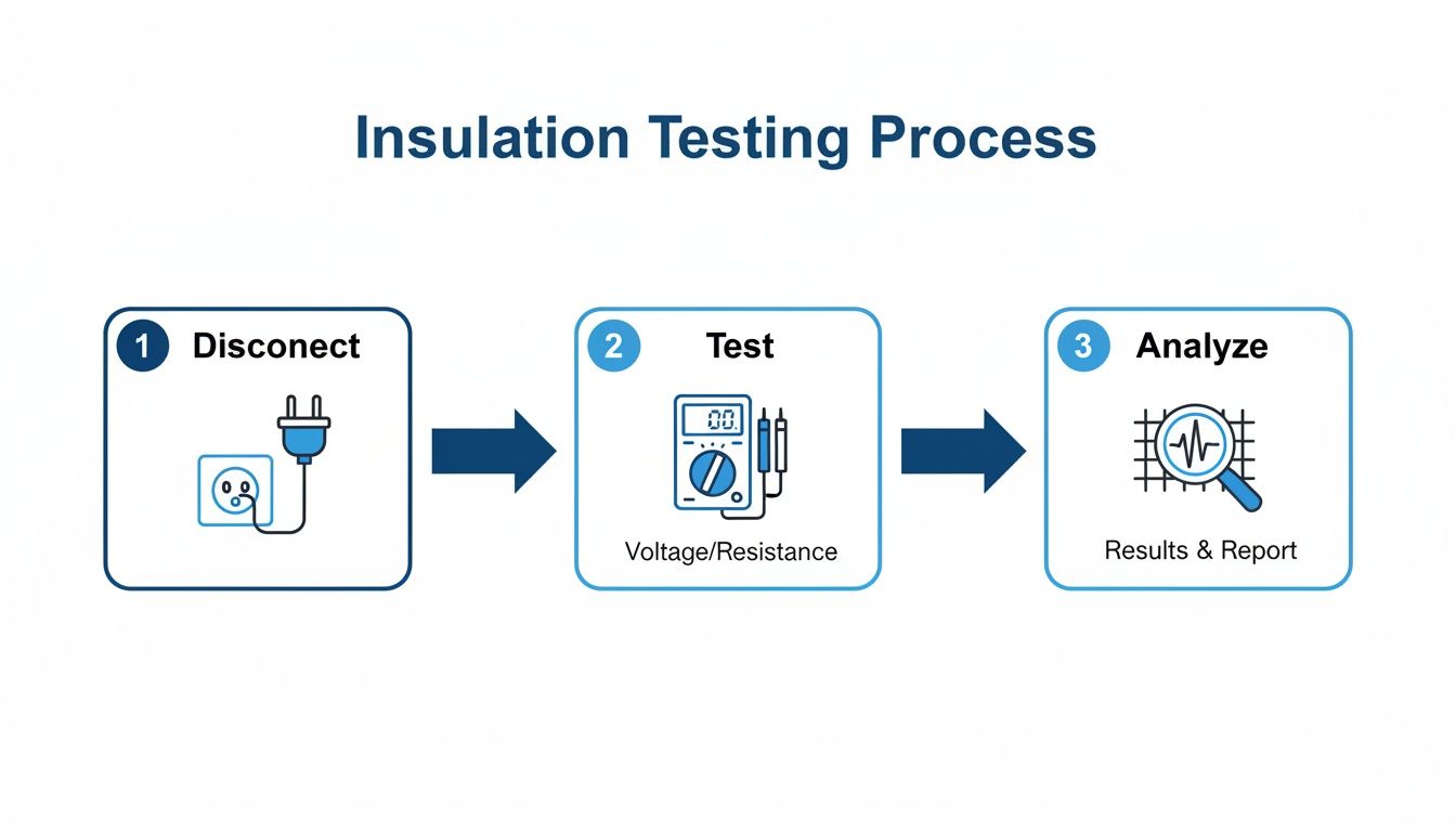
Insulation Resistance Testing: Before you even think about flipping the switch, a megger test is non-negotiable. This confirms that there are no conductive paths between energized parts and the ground, proving the insulation wasn't damaged during its journey to you.
Functional Checks: Test everything. Manually open and close every breaker. Verify trip settings. Check all safety interlocks and protective relays to ensure they work exactly as they should.
Building a Maintenance Program That Actually Works
After commissioning, the game shifts to proactive maintenance. A well-thought-out preventive maintenance (PM) plan is your best defense against catastrophic failures and the brutal costs of unplanned downtime.
A robust maintenance plan treats your power distribution center like the critical asset it is. It's not just about cleaning; it's about using diagnostic tools to see the invisible and predict the future health of your electrical system.
A comprehensive PM program for your power distribution center has to include a few key activities on a strict schedule.
Key Preventive Maintenance Tasks
Infrared Thermography: At least once a year, get an IR scan done on all electrical connections while the system is under a normal load. This is the fastest way to spot "hot spots" from loose connections, which are a major fire and failure hazard.
Routine Cleaning: Dust and grime are silent killers. They degrade insulation and trap heat. A scheduled shutdown for a proper cleaning, using approved methods, is absolutely essential for long-term health.
Component Exercising: Circuit breakers and switches that sit idle for years can get stiff and refuse to operate when you need them most. Periodically "exercising" them—just opening and closing them a few times—ensures they'll work in an emergency.
Combine a meticulous installation with a proactive maintenance strategy, and you can count on your PDC to operate safely and reliably for decades to come.
Your Top Questions About Power Distribution Centers, Answered
When you're dealing with industrial electrical gear, questions are a good thing. It means you're being thorough. Even the most seasoned plant engineers and OEMs run into tricky situations when specifying, installing, or upgrading a power distribution center. Let's tackle some of the most common ones we hear.
We'll cover everything from key component differences to the critical safety math, giving you practical insights straight from the field. Getting these details right is the key to a system that’s not just efficient, but also safe and up to code.
What’s the Real Difference Between a Switchboard and Switchgear?
People use these terms interchangeably, but they are fundamentally different beasts. The biggest distinctions come down to their construction, the standards they're built to, and where you typically find them.
Switchgear is the heavy-hitter, built to tough ANSI/IEEE C37 standards and designed for serious industrial applications where downtime is simply not an option. Think of it as a collection of individual, heavily armored compartments, each with a withdrawable circuit breaker. This design makes maintenance safer and easier and prepares it for much higher fault currents.
On the other hand, you have switchboards. These are governed by UL 891 and are more at home in commercial buildings and lighter industrial spots. Their components are typically mounted on a single, shared frame. This makes them more compact, but you lose the compartmentalization. The right choice really boils down to your required fault rating, system voltage, and just how critical easy maintenance access is for your operation.
How Do I Figure Out the Right Short Circuit Current Rating?
This is one area where you absolutely cannot guess. Determining the proper Short Circuit Current Rating (SCCR) is a critical safety calculation that has to be done by a qualified electrical engineer. It’s not just a quick lookup—it requires a full-blown fault current study of your entire electrical system, starting from the utility’s transformer and tracing all the way to where your PDC will be installed.
The study calculates the absolute maximum amperage that could slam through the system in a worst-case short circuit.
The rule is simple and absolute: The SCCR of your power distribution center must be equal to or greater than the available fault current at its connection point. Anything less is a major safety hazard and a direct violation of the electrical code.
Can I Add More Circuits to My PDC Later On?
Yes, but only if you planned for it from day one. It all comes down to foresight during the initial design. The best practice is to always spec a new PDC with a mix of "spaces" (the empty physical slots for future breakers) and "spares" (breakers that are fully installed and wired but not yet in use).
Having that capacity built-in makes adding a new motor or piece of equipment a simple, quick, and relatively cheap task. Without it, you’re looking at a major project that could involve a full shutdown, tricky modifications to the existing gear, or even having to replace an entire section of your PDC. And remember, any time you modify the system, the law says you need a new arc flash hazard analysis to keep your team safe.
Why Is an Arc Flash Study So Important for a PDC?
Think of an arc flash study as non-negotiable life insurance for your team. It's a detailed engineering analysis that calculates the potential intensity of an arc flash—a violent, explosive release of energy from an electrical fault—at different points inside the PDC.
The study determines two critical things: the incident energy (the thermal energy, measured in cal/cm²) and the arc flash boundary (a safe approach distance). This isn't just a report that sits in a file; the data is printed on warning labels placed directly on the equipment. These labels tell qualified electricians the specific hazard level and, most importantly, the exact Personal Protective Equipment (PPE) they must wear to work on or near that gear while it's energized. This isn't just a good idea—it's mandated by NFPA 70E and OSHA to prevent catastrophic injuries.
At E & I Sales, we don't just sell components; we engineer complete, reliable systems. We specialize in designing custom UL-listed control panels and integrating them seamlessly with robust power distribution centers. From the first sketch to final commissioning, our team has the expertise to make sure your project is safe, compliant, and ready for whatever you throw at it. See how we build turnkey solutions at https://eandisales.com.
Picture this: a fire breaks out in a massive warehouse. Instead of every sprinkler in the building drenching the entire facility, only the ones directly over the flames kick on. That’s Zone Selective Interlocking (ZSI) in a nutshell. It's a smart communication system between circuit breakers that pinpoints and isolates a problem with surgical precision.
This simple idea solves one of the biggest headaches in power system design.
Solving the Protection vs. Selectivity Puzzle
For years, electrical engineers have been stuck in a trade-off between protection speed and system reliability. To keep a small fault on a branch circuit from tripping the main breaker and killing power to everything—a practice called selective coordination—we've had to intentionally slow down our upstream breakers. We program in time delays to give the device closest to the fault the first chance to open.
It works, but it comes at a steep price. The longer that fault is allowed to cook, the more destructive energy it unleashes. This dramatically increases the danger of a catastrophic arc flash. So you're left with a terrible choice: accept a higher arc flash risk to keep the lights on, or sacrifice uptime for faster, safer fault clearing.
Zone Selective Interlocking completely rewrites the rules, getting rid of that compromise. It establishes a high-speed communication link between breakers.
With ZSI, the breaker closest to the fault still trips instantly. But at the same time, it sends a signal "upstream" to the other breakers telling them to hold off. That simple "wait" command prevents a cascading outage and keeps the problem contained to the smallest possible area.
How ZSI Gives You the Best of Both Worlds
By enabling this kind of intelligent, localized response, ZSI delivers both lightning-fast tripping and rock-solid coordination. In the real world, this translates to huge benefits:
Massively Improved Safety: Clearing a fault in a few milliseconds instead of hundreds of them drastically cuts down the incident energy of an arc flash. This can be the difference between a minor event and a life-threatening one, often lowering the required level of Personal Protective Equipment (PPE).
Maximum Uptime: Say goodbye to nuisance trips that take out an entire production line or data center floor. ZSI ensures only the single affected circuit goes down, which is a massive win for operational continuity.
Less Equipment Damage: The faster you clear a fault, the less thermal and mechanical stress you put on your gear. That means less damage to cables, bus bars, and transformers, leading to faster repairs and lower replacement costs.
Essentially, ZSI transforms a rigid, pre-programmed protection scheme into a dynamic system that can think and react. It gives your power system the intelligence to know exactly where a fault is happening and to act only where needed. This capability has made ZSI a cornerstone technology for any modern industrial facility that values safety and reliability.
How Zone Selective Interlocking Actually Works
Let's stick with that fire sprinkler analogy. Now, imagine each sprinkler head couldn't just detect a fire, but could instantly text the main water valve: "Hold on, I see the flames here. I've got this." That’s pretty much the logic Zone Selective Interlocking (ZSI) brings to an electrical system.
At its heart, ZSI is a high-speed conversation between circuit breakers, all arranged in zones—from the main breaker all the way down to individual branch circuits. When a downstream breaker sees a fault, it doesn't just quietly prepare to trip. It simultaneously sends a tiny, instantaneous "blocking" signal to the breaker directly upstream.
This signal is a simple but powerful message: "I see the fault in my zone, and I am handling it." The local breaker then opens in milliseconds, clearing the fault with surgical precision. The upstream breaker, having received the signal, simply holds its position, maintaining its standard (and longer) time delay. It's now on standby, ready to act as a backup only if the first device fails to do its job.
The Communication Backbone
This intelligent conversation between breakers happens over dedicated wiring. The exact method really depends on the age and design of the switchgear you're looking at.
Hardwired Pilot Wires: In a lot of traditional setups, this is handled by a simple pair of low-voltage wires running directly between the electronic trip units of the breakers. It’s a direct, no-fuss, and incredibly reliable connection.
Internal Communication Buses: More modern "smart" switchgear often takes an integrated approach. Here, ZSI signals travel over an internal data bus—much like a small computer network—that connects all the breakers within the assembly.
This communication is the secret sauce. It’s what transforms a static, time-based protection scheme into a dynamic, responsive one.
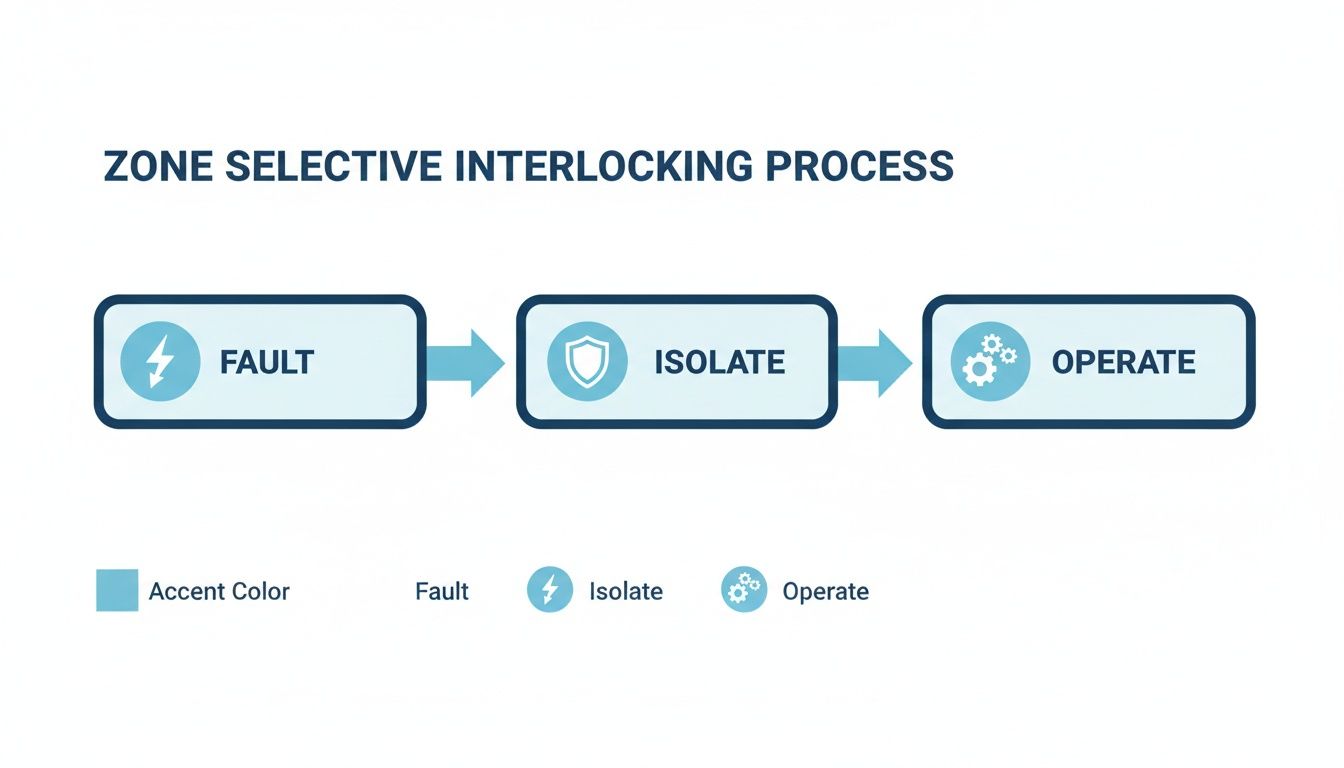
The flowchart below shows just how simple and elegant this process is—a logical sequence that delivers both speed and selectivity.
Tracing the ZSI Signal Path
Let’s walk through a fault in a typical power distribution system to see ZSI in action. Imagine a dead short on a branch circuit feeding a large motor.
Fault Detection: The branch circuit breaker (we'll call it Breaker C) immediately senses the massive rush of current.
Signal Transmission: Instantly, Breaker C sends a "restrain" signal up to its feeder breaker (Breaker B). Breaker B gets the message and, in turn, passes a restrain signal up to the main (Breaker A).
Localized Trip: With its upstream neighbors now waiting patiently, Breaker C trips almost instantaneously—typically within 50 milliseconds—and isolates the fault right where it happened.
System Stability: Breakers A and B, having received their "hold" instructions, stay closed. Power to every other healthy circuit remains on, completely unaffected. That’s maximum uptime.
Now, what if Breaker C failed to trip for some reason? The restraining signal would stop. Breaker B would then see the fault, its own time delay would expire (say, at 200 milliseconds), and it would open as the next line of defense. This built-in backup function ensures the system stays protected, no matter what.
The "interlocking" logic is what makes the whole thing work so well. The upstream device’s action is literally locked based on the status of the downstream device. It’s a cooperative strategy that prevents cascading, widespread outages.
This coordination technique has been around for about four decades, but it really became a cornerstone of modern industrial safety as digital microprocessor breakers became the norm. Modern ZSI uses incredibly fast electronic signaling, which turns a traditional, slow time-graded system into something dynamic that dramatically cuts down on the thermal and mechanical stress equipment sees during a fault. For system designers, this means you can get incredible selectivity without having to compromise on speed or safety. You can learn more about how ZSI fits into modern power system studies on ETAP's product page.
Faster Tripping and Slashed Arc Flash Hazards
The engineering behind Zone Selective Interlocking is clever, but its real-world value is where things get exciting. It’s about safety and reliability. By turning a rigid, pre-programmed protection scheme into one that thinks and reacts, ZSI gets right to the heart of the biggest risks in power distribution.
The single most critical benefit? A massive reduction in arc flash energy.
The destructive force of an arc flash boils down to a simple formula: energy equals current squared times time (I²t). You can't change the massive fault current available from the utility, but you absolutely can control the time component. That's ZSI's superpower—it allows the breaker closest to the fault to open almost instantly, dramatically cutting down the time the arc can burn.
A Tale of Two Clearing Times
Let's put some numbers on it. Picture a fault deep within a system that relies on traditional time-delay coordination. To avoid a nuisance trip, the main upstream breaker is intentionally set to wait, maybe for 300 milliseconds. That’s a long time for thousands of amps to be wreaking havoc.
Now, let's run the same scenario with ZSI enabled. The local breaker sees the fault, instantly signals the upstream breaker to hold off, and clears the fault itself—all in about 50 milliseconds.
That 250-millisecond difference is everything. It's the gap between a contained event and a catastrophic explosion that destroys switchgear and puts lives at severe risk.
The table below breaks down just how significant this time reduction is. By slashing the clearing time, ZSI directly lowers the incident energy a worker could be exposed to.
ZSI Impact on Fault Clearing Time and Arc Flash Energy
Scenario
Fault Location
Clearing Time (ms)
Incident Energy (cal/cm²)
Resulting PPE Category
Traditional Coordination
Motor Control Center Bus
300 ms
12.5 cal/cm²
Category 3
With ZSI Enabled
Motor Control Center Bus
50 ms
2.1 cal/cm²
Category 1
As you can see, dropping the trip time from 300ms to 50ms can easily reduce the required PPE from heavy, cumbersome suits to much lighter gear, making work safer and more efficient.
Keeping the Lights On and the Business Running
Safety is priority one, but ZSI also delivers a huge boost to the bottom line by maximizing uptime. In a conventionally coordinated system, a fault on a single motor feeder might be just slow enough to trip the main breaker for the entire MCC. Suddenly, an entire production line grinds to a halt over a localized problem.
ZSI stops these cascading outages cold. It makes sure only the device right next to the fault opens, leaving the rest of the facility online and productive.
For any plant manager or facility operator, uptime is money. Zone Selective Interlocking is a direct investment in operational continuity, protecting your revenue-generating processes from unnecessary and costly shutdowns.
This kind of surgical precision is priceless in factories, data centers, and hospitals, where every second of downtime costs a fortune. It elevates your protection scheme from a blunt instrument to a finely-tuned tool. Of course, technology is only one piece of the puzzle. The best-designed system still needs people who know how to work safely, which is why comprehensive https://eandisales.com/uncategorized/arc-flash-safety-training/ is non-negotiable.
This double-win of world-class safety and bulletproof reliability makes zone selective interlocking a must-have for any modern power system. It's not just about ticking a box for code compliance—it's about building an operation that is fundamentally safer, more resilient, and more profitable.
Alright, let's take that section on designing a ZSI system and give it a more hands-on, expert feel. Moving from the theoretical "what is ZSI" to actually building one that works is where the rubber really meets the road.
Designing and Implementing a ZSI System
Moving from a drawing board concept to a real-world, reliable Zone Selective Interlocking system is all about sweating the details. It really boils down to three make-or-break pillars: picking the right hardware, getting the settings dialed in perfectly, and making sure the wiring is flawless. Get these right, and you've built a powerful safety net. Get them wrong, and you've just got a diagram and a false sense of security.
The whole thing starts with the protective devices themselves. You can't just grab any old breaker off the shelf; they need to be built for this. Specifically, their electronic trip units must have the dedicated input and output terminals to send and receive those critical "hold off" signals.
Selecting Compatible Hardware
When you're putting together a bill of materials, you have to be certain that every device in the chain—from the main service entrance down to the feeder breakers—can speak the same ZSI language.
Breaker and Relay Compatibility: Make sure every single breaker and protective relay you specify is ZSI-enabled. It's sometimes possible to mix and match brands, but that means you'll be spending a lot of time buried in technical manuals to confirm they'll actually talk to each other. For anything complex, sticking with a single manufacturer's product family is often the path of least resistance.
Trip Unit Smarts: The electronic trip unit is the brain of this whole operation. You need to confirm it allows you to adjust the short-time pickup (Isd) and, most importantly, the short-time delay (tsd). These are the very settings ZSI manipulates.
Zone Limits: Dig into the manufacturer's spec sheets to see how many ZSI zones a single breaker can handle. Trying to make a device manage more zones than it was designed for is a recipe for unreliable performance.
If you're looking to spec a new system or upgrade an old one, it’s always a good idea to see what the established brands are offering. You can get a good sense of modern capabilities by checking out guides on specific gear, like a detailed overview of an ABB circuit breaker.
Configuring Settings and Coordination
With your hardware picked out, the real engineering begins: programming the settings. This is driven by a coordination study, and your Time-Current Curves (TCCs) are your best friend here. TCCs let you see exactly how your breakers will behave and interact when a fault hits.
The trick is to set up your short-time delays for proper coordination as if ZSI didn't exist. Think of it as your failsafe. For instance, a downstream breaker might get a 100 ms delay, while its upstream parent gets a 300 ms delay. With ZSI active, the system bypasses that built-in delay for the breaker closest to the fault, letting it trip in, say, 50 ms, while telling the upstream breaker to hold back.
A core philosophy in ZSI design is to first build a solid, traditional time-based coordination scheme. ZSI then acts as an intelligent accelerator, giving you incredible speed without sacrificing the fundamental backup protection of your staggered delay settings.
Critical Wiring and Verification
The physical wires connecting your devices are the nervous system of your ZSI scheme. The best breakers and the most brilliant settings mean absolutely nothing if the signal can't get through cleanly. Honestly, this is where most implementations go sideways.
Key Wiring Considerations:
Dedicated Cabling: ZSI signals need their own dedicated, twisted-pair shielded wire. This is non-negotiable. You have to shield the signal from the electrical noise and interference blasting off nearby power cables, which could easily corrupt it.
Correct Polarity: The ZSI input and output terminals are polarized. Getting them backward is a classic, easy-to-make mistake that completely defeats the system because the restraining signal will never be recognized. Double- and triple-check the polarity against the manufacturer's diagrams.
Current Transformer (CT) Selection: The breaker's trip unit is only as smart as the information it receives. That information comes from the CTs. Make sure your CTs are sized correctly for both the normal load and the potential fault currents. And just like the signal wires, their polarity has to be right, or the breaker could completely misinterpret what's happening during a fault.
By locking down these three areas—hardware, settings, and wiring—you can build a Zone Selective Interlocking system that you can truly count on. It’s this disciplined approach that ensures the system will do its job when the worst happens, protecting both people and equipment.
Testing and Troubleshooting Your ZSI Scheme
A perfectly designed Zone Selective Interlocking scheme on paper means nothing until it's proven in the field. Commissioning and testing aren't just a final checkbox; they are the critical steps that turn a safety blueprint into a real-world, reliable asset. This is where you validate that every wire, setting, and signal will do its job when a fault finally happens.
Think of it like inspecting a parachute. You trust the engineering, but you still meticulously check every strap and cord before the jump. For ZSI, this means running through static checks before power-up and then dynamic functional tests to confirm the whole system talks to each other correctly. Cutting corners here is simply not an option.
Pre-Energization Checks and Verification
Before you even think about energizing the system, a few methodical checks can catch over 90% of the most common installation mistakes. These are the basics, but getting them right prevents a world of headaches later.
Wiring Continuity and Polarity: This is ground zero for ZSI issues. Grab a multimeter and verify point-to-point continuity on all ZSI control wiring. More importantly, double-check the polarity of the ZSI input and output terminals against the manufacturer's drawings. Reversed polarity is an incredibly easy mistake to make, and it completely disables the interlocking logic.
Settings Verification: Get the coordination study in hand and physically walk down every breaker. You need to verify that the short-time pickup and delay settings on each trip unit match the engineered values to the letter. A single digit off can throw the entire coordination scheme out the window.
Insulation Resistance Testing: A quick "Megger" test on the ZSI control wiring is a must. This will tell you if there are any nicks or breaks in the insulation that could cause shorts or grounds, leading to phantom signals or a complete loss of communication.
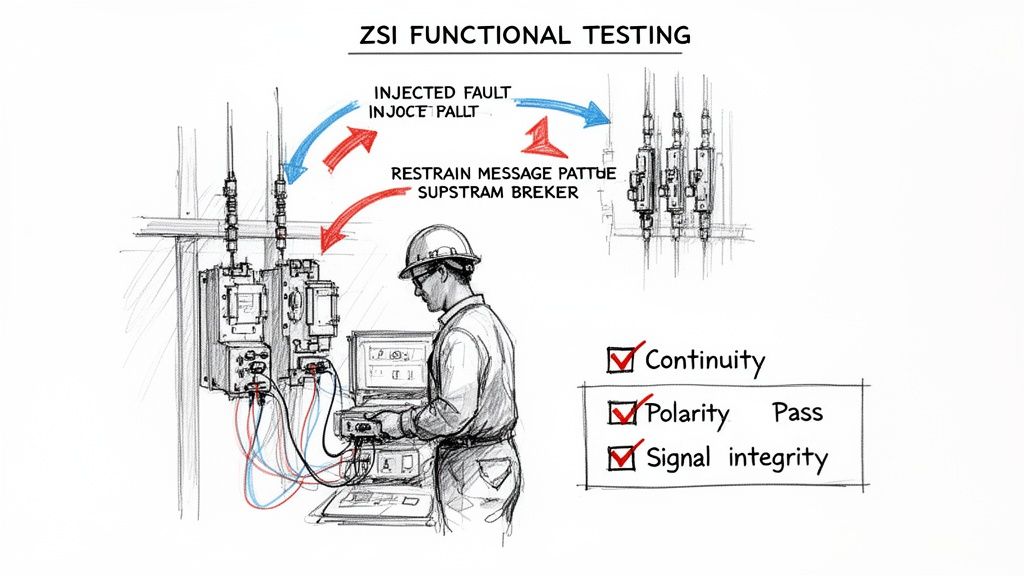
Functional Testing with Injection Sets
Once the static checks are done, it's time to make the system prove itself. We do this safely with a secondary current injection test set. This nifty tool essentially tricks the breaker's brain into thinking it sees a massive fault current, all without putting the actual power system at risk.
The whole point here is to trace the "restraining" signal's journey from start to finish. You'll inject a simulated fault current into a downstream breaker and watch for two things:
The downstream breaker trips instantly (or on its own short-time setting), just as it should.
The upstream breaker gets the restraining signal and successfully holds for its full coordinated time delay, proving the ZSI logic is working.
This functional test is the moment of truth. It goes beyond checking individual components and confirms that the entire ZSI system—breakers, wiring, and settings—operates as one cohesive, intelligent unit.
Common Troubleshooting Scenarios
Even the most carefully planned installations can hit a snag. When a functional test doesn't go as expected, the problem almost always boils down to just a handful of common issues. A methodical approach is your best friend here. If you need a refresher on the basics, understanding what can cause a breaker to trip provides some great foundational context.
To help you get straight to the root cause, here’s a quick-hit checklist for troubleshooting common ZSI symptoms.
Common ZSI Troubleshooting Checklist
Symptom
Potential Cause
Diagnostic Step
Solution
Upstream breaker trips instantly (doesn't hold)
Lost restraining signal due to wiring issue
Verify continuity and polarity of ZSI control wiring between the downstream and upstream breakers.
Physically verify the ZSI function is enabled and the short-time delay is set per the coordination study.
Adjust trip unit settings to match the engineered values.
Upstream breaker holds, but downstream breaker doesn't trip
Test current is below downstream breaker's pickup setting
Confirm the injected current from the test set is high enough to exceed the downstream breaker's short-time or instantaneous pickup threshold.
Increase the injected test current to the proper level.
All breakers trip simultaneously (no selectivity)
ZSI function is disabled on all breakers
Check the trip unit settings on each breaker involved in the scheme to ensure ZSI is turned on.
Enable the ZSI feature in the trip unit's programming menu.
Intermittent or unreliable restraining
Damaged control wiring or loose connection
Perform an insulation resistance test (Megger) on the ZSI wiring and physically inspect all terminal block connections for tightness.
Replace damaged wiring or re-torque loose terminal screws.
If an upstream breaker is tripping too fast, it's a clear sign the restraining signal isn't getting through. Start with the simplest and most likely culprits—the wiring—before you start digging into more complex device settings. This structured approach will save you time and lead to a more reliable fix every time.
ZSI on the Factory Floor: Real-World Applications
Theory is one thing, but putting it to work on the factory floor is where Zone Selective Interlocking (ZSI) really shines. It's a clever concept, for sure, but its real power is in solving tangible safety and uptime problems, especially in the systems that drive heavy industrial machinery.
You see this most clearly in Motor Control Centers (MCCs). Think of an MCC as the nerve center for an entire production line. A single fault on one motor feeder can easily bring everything to a grinding halt. Let's walk through a common scenario: a manufacturing plant is installing a brand new, UL-listed 480V MCC.
Without ZSI, if a big motor feeder shorts out, the main breaker for the whole MCC has to sit and wait. It's programmed with a long delay to try and coordinate with the downstream breakers. That delay might stop the whole plant from going dark, but it also allows a huge amount of dangerous arc flash energy to build up, often forcing anyone nearby into bulky Category 3 or 4 PPE.
A Case Study in Smarter Safety and Uptime
Now, let's say the engineers on this project decided to implement ZSI in their new MCC. This simple decision completely changes the outcome.
When a fault happens on a motor starter, the feeder breaker trips almost instantly—we're talking under 50 milliseconds. At the exact same moment, it fires a restraining signal up to the main MCC breaker, telling it, "Stand down, I've got this."
The result? A massive reduction in incident energy on the main bus. The arc flash danger is completely contained to the specific faulted bucket. The calculated energy level plummets, often making it safe enough for technicians to work with much less restrictive PPE. It’s a win-win: safety gets a huge boost, and you avoid tripping the entire MCC offline for a localized problem.
This shift from a slow, time-based coordination scheme to a fast, communication-based one isn't just an abstract concept. It's a practical, real-world solution that proves ZSI is a critical tool for modern industrial safety and reliability.
Taming Those Big Motor Inrush Currents
Here’s another place ZSI is a game-changer: dealing with large motors. When a big motor kicks on, the massive inrush current it draws can look a lot like a short circuit to a standard breaker, causing nuisance trips. To get around this, engineers sometimes have to dial back the protection settings to let the motor get through its startup phase, which unfortunately compromises safety.
ZSI provides a much more elegant answer. You can tune the system to intelligently ignore the predictable, brief surge of an inrush current but still react instantaneously to a genuine short circuit. This gives you bulletproof protection when the motor is most vulnerable, all without the headache of costly false trips that shut down production.
Even after getting the hang of Zone Selective Interlocking, you're bound to have some practical questions when it's time to put it to work. We see it all the time—engineers, maintenance managers, and facility operators need to balance the big safety wins with the real-world headaches of getting it done.
This section cuts straight to the chase, answering the most common questions we hear about cost, compatibility, and what happens when things go wrong. Let's clear up any confusion so you can feel confident about using ZSI to make your electrical system safer and more reliable.
Can I Retrofit ZSI Into My Existing Switchgear?
That’s the million-dollar question, isn't it? The answer is a solid "it depends." Retrofitting zone selective interlocking is definitely possible, but it all comes down to what kind of circuit breakers you're working with. The one non-negotiable is that your breakers need electronic trip units with dedicated ZSI input and output terminals.
If your switchgear is packed with old-school thermal-magnetic breakers or even basic electronic ones, this isn't a simple wiring project. You’d be looking at a full-blown replacement of the breakers with modern, ZSI-ready models. But if your gear already has compatible breakers, just adding the control wiring is a relatively simple upgrade that delivers a huge jump in safety.
What Happens If a ZSI Signal Wire Fails?
This is one of the most important things to understand from a safety perspective. Any properly designed ZSI system is built to be fail-safe. If a signal wire gets cut, comes loose, or shorts out, that communication link between breakers is broken. When that happens, your system doesn't just go dark—it automatically reverts to its standard, time-delayed coordination.
The upstream breaker simply never gets the "hold off" signal from the downstream device that saw the fault. So, it does what it's programmed to do: it trips based on its own short-time delay settings, ensuring you still have reliable backup protection. The system defaults to being slower, but it never defaults to being unsafe.
This built-in safety net means a simple wiring problem won't leave your people or equipment exposed. The worst-case scenario is that you lose the speed of ZSI, not the protection itself.
How Does ZSI Compare to Other Arc Flash Methods?
ZSI is a fantastic tool, but it's just one tool in the arc flash mitigation kit. It’s important to know where it shines compared to the other options out there.
Arc-Resistant Switchgear: Think of this as a brute-force solution. It’s designed to physically contain and redirect the explosive energy of an arc blast. It's incredibly effective at protecting people standing in front of the gear, but it's a major capital investment and does nothing to reduce the actual incident energy.
Maintenance Mode Switches: These are temporary overrides that let a technician manually set a breaker to trip faster while they work. They work well, but they are 100% dependent on someone remembering to flip the switch on and off. Human error is a real risk.
Optical Arc Detection Systems: Using light sensors, these systems can spot an arc flash and send a trip signal in just a few milliseconds. They are the absolute fastest solution available, but they are also the most complex and expensive to install.
Zone selective interlocking hits that sweet spot right in the middle. It's an active, full-time system that slashes incident energy without the high cost and complexity of optical systems, making it one of the most practical and cost-effective arc flash reduction strategies you can implement.
At E & I Sales, we live and breathe this stuff. We design and build custom UL-listed control panels and motor control centers with advanced protection like ZSI baked in from day one. We’re here to help you sort through the technical details and make sure your systems are safe, dependable, and up to code. Ready to talk about your next project? Contact us today and see what our expertise can do for you.
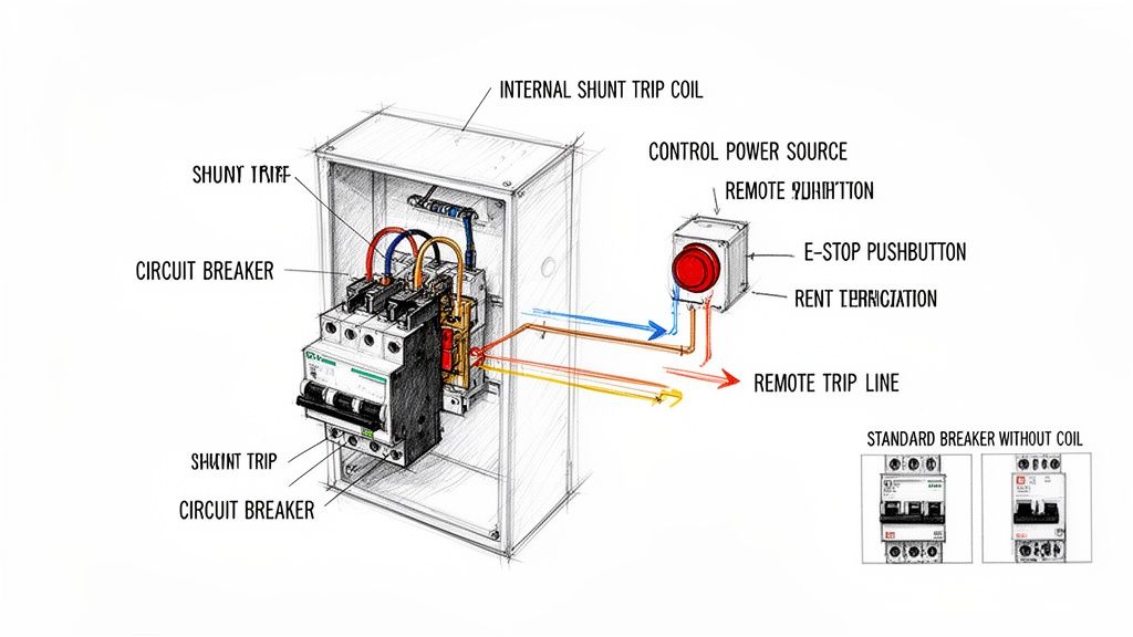
At its core, a wiring diagram for a shunt trip circuit breaker is pretty straightforward. It shows an internal coil wired up to a remote device, which could be anything from an E-stop button to a fire alarm contact.
When that remote device closes the circuit, it shoots a control voltage to the coil. That coil then mechanically forces the breaker to open instantly, cutting power from a safe distance. This is a whole different ballgame compared to a standard breaker, which just sits there waiting to react to overcurrent. With a shunt trip, you're in control.
What a Shunt Trip Circuit Breaker Actually Does
Before you start tracing wires, it's crucial to get why a shunt trip breaker is an absolute non-negotiable in so many industrial safety systems. A standard thermal-magnetic breaker is passive—it only trips after an overcurrent or short circuit has already happened. A shunt trip breaker, on the other hand, acts on command. It gives you a way to kill a circuit immediately and remotely, making it a cornerstone of modern safety protocols.
Think of it as the electrical world's emergency brake. A regular breaker protects the equipment; a shunt trip protects your people and your facility. You'll see them everywhere, from machine shops to complex automated lines. In high-risk fields like those you find in metal fabrication companies, the ability to stop heavy machinery instantly isn't just a feature—it's a necessity.
The Key Players in a Shunt Trip System
A shunt trip system is really quite simple when you break it down. You’ve just got four main parts working together. Understanding how they interact is the first step to getting the installation right.
The Circuit Breaker: This is your main device. It has all the standard overcurrent protection but includes an internal port for the shunt trip accessory.
The Shunt Trip Coil: It's a small solenoid coil that lives inside the breaker. When it gets hit with voltage, it creates a magnetic field that physically shoves the breaker's trip mechanism open.
The Control Power Source: This is a separate, dedicated power source that supplies the juice—like 24V DC or 120V AC—to activate the coil. It has to be reliable and sized correctly for the job.
The Initiating Device: This is your trigger. It's usually a normally open (N.O.) contact, like an emergency pushbutton, a relay from a fire alarm panel, or even an output from a PLC.
Shunt Trip vs. The Other Guys
It's easy to get shunt trips, standard breakers, and undervoltage release breakers mixed up. But getting their functions straight is critical if you want to apply and wire them correctly.
A standard breaker is completely passive. It only cares about what’s happening on the main circuit it's protecting and has no external control inputs.
An undervoltage release (UVR) breaker is the exact opposite of a shunt trip. It needs a continuous control voltage just to stay closed and will automatically trip if that voltage is lost. We use these when we don't want a machine to suddenly restart after a power outage.
A shunt trip breaker, however, stays closed until a control voltage is applied to its coil. It’s a "trip on command" device, making it perfect for E-stop circuits where you need deliberate action to cut the power.
Choosing the right coil voltage is a common decision point when designing a control panel. It depends entirely on your control system's standard voltage.
Shunt Trip Coil Voltage Selection for Common Applications
Coil Voltage
Typical Control Source
Common Industrial Applications
Key Design Consideration
24V DC
PLC Outputs, Safety Relays, Low-Voltage Control Circuits
Automated machinery, robotics, UL508A control panels
Most common for modern control systems; minimizes shock hazard in the control cabinet.
120V AC
Control Transformers, Lighting Circuits, Fire Alarm Panels
Building automation, HVAC systems, simpler machine controls
Widely available and simple to source, but requires careful routing of AC control wiring.
240V AC
Direct Line Voltage Tap (Phase-to-Phase or Phase-to-Neutral)
Heavy industrial equipment, motor control centers (MCCs)
Can simplify wiring by eliminating a control transformer, but introduces higher voltage into the control circuit.
48V DC
Telecom Power Supplies, Battery Backup Systems
Telecommunications facilities, data centers, substations
Common in DC-powered environments; ensures trip functionality during AC power loss if on a UPS.
This choice impacts everything from wire sizing to panel layout, so getting it right upfront saves a lot of headaches later.
This foundational knowledge is key for any plant engineer or system integrator trying to build a reliable and code-compliant UL control panel. Being able to remotely and decisively kill power isn't just a nice-to-have; it's a critical safety function. If you're working with specific brands, digging into the features of an ABB circuit breaker and its available accessories is a great next step.
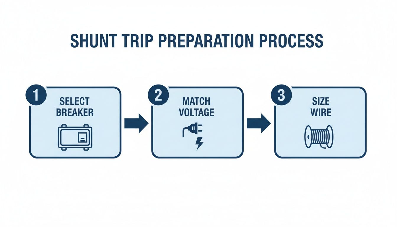
Nailing the Prep Work: Component Selection and Safety Checks
A rock-solid shunt trip installation is built on smart decisions made long before you even touch a wire. Getting the component selection and initial safety checks right from the get-go is everything. It's the difference between a smooth, reliable system and one plagued by costly rework and headaches down the road.
First things first, you need a circuit breaker that’s actually designed to have a shunt trip accessory installed. This isn't a "one-size-fits-all" situation. Always, and I mean always, check the manufacturer's datasheet to confirm compatibility. Trying to force a shunt trip onto a breaker that isn't built for it is a non-starter and a huge safety hazard.
Matching Coil Voltage to Your Control System
One of the most common—and frustrating—mistakes I see in the field is a mismatch between the shunt trip coil's voltage and the control power source. That little coil is just a solenoid, and if you feed it the wrong voltage, it’s either not going to work or you’ll burn it out.
The common options are usually 120V AC, 24V DC, or 24V AC.
Picture this: A beautiful new UL control panel is built around a slick 24V DC PLC system, but someone spec'd a breaker with a 120V AC shunt trip coil. Suddenly, you're scrambling for a last-minute control transformer and running extra wires, blowing up the budget and the timeline. Avoid the pain and confirm your control voltage before you order anything.
Sizing Your Control Wiring and Fuses
Once the voltage is sorted, you've got to size the control wiring and its overcurrent protection correctly. Shunt trip coils are inductive loads, which means they have an inrush current—a big gulp of amperage for a split second when it first energizes. This is a tiny detail that can cause major problems if you ignore it.
Dive back into that manufacturer datasheet and hunt for two key numbers:
Sealed/Holding Power: The steady power the coil needs (in VA or Watts).
Inrush Current/VA: The peak power it pulls to activate the trip.
Your control wiring (typically 14-24 AWG) has to handle that inrush spike without a major voltage drop. Even more critical is the fuse or mini-breaker protecting that circuit. It needs to be tough enough to let the inrush current pass without nuisance tripping, but sensitive enough to blow if there's a real overcurrent problem. A fast-acting fuse might pop every time you power up, while an oversized one offers zero protection.
A well-executed shunt-trip setup is a massive safety upgrade. Modern modules can trip a breaker in under 50–150 milliseconds of receiving a signal, allowing automated shutdowns that are lightyears faster than any human. In fact, studies show that up to 20–35% of control panel wiring issues found during commissioning trace back to mismatched control voltages or improperly fused trip circuits. It just shows how critical these upfront decisions really are. Find out more about how breakers work on Wikipedia.
For panel builders and integrators, this kind of meticulous planning is non-negotiable. Our complete guide on industrial control panel design dives even deeper into these principles. Getting these details right from the start is how you build a final UL-listed panel that’s both safe and absolutely dependable.
Taking the Shunt Trip Breaker Diagram from Paper to Panel
Alright, you've got the schematic figured out. Now comes the real test: translating that drawing into a clean, reliable circuit in the panel. This is where a little experience goes a long way. We'll walk through the wiring for two of the most common setups you'll see in the field—a classic Emergency Stop button and a more modern PLC-controlled trip.
The idea behind it is simple. You're just creating a switchable circuit that sends power to that little shunt trip coil. Once the initiating device—be it a button or a PLC relay—closes that circuit, voltage hits the coil, and boom, the breaker trips. Simple concept, but getting the details right is what makes it safe and dependable.
Before you even strip a wire, the prep work is key.
Nailing this sequence—matching the breaker, coil voltage, and wire gauge—is the first step to avoiding some of the most common headaches during installation.
Wiring the Classic Emergency Stop (E-Stop) Circuit
The E-Stop button is the bread and butter of shunt trip applications. It’s the big red button that gives anyone a way to kill power to a machine from a safe distance, a non-negotiable safety feature on pretty much any industrial equipment.
You only need a few parts for this job:
A solid control power source (a 120V AC control transformer is a common choice).
A fuse or small breaker to protect that control circuit.
The E-Stop button itself, which needs at least one normally open (N.O.) contact.
And of course, the shunt trip breaker.
The wiring couldn't be more straightforward. Your control power "hot" leg runs through the fuse, then heads to one side of the E-Stop's normally open contact. The other side of that contact wires directly to one of the shunt trip coil terminals (usually marked S1 or C1). To finish it off, the second coil terminal (S2 or C2) ties back to the neutral or common side of your control power.
When everything is normal, that N.O. contact is open, so the coil sees no voltage. The second someone hits that E-Stop, the contact slams shut, energizing the coil and tripping the breaker instantly.
Field Tip: Don't skimp here. Always use a proper, clearly labeled E-Stop button—the big, red, mushroom-head style. You want it to be unmistakable in a crisis. Using a normally open contact is also critical; it ensures the coil is only powered for a split second, preventing it from overheating and burning out.
Hooking Up a PLC-Controlled Shunt Trip
In automated factories, the signal to trip often comes from a Programmable Logic Controller (PLC). This lets the system automatically shut down equipment based on things like sensor faults, over-temperature alarms, or safety interlocks. The wiring is nearly identical to the E-Stop, but you're swapping the manual button for a PLC output relay.
The power flow is the same. Start with your fused control power, which feeds the "common" terminal on a PLC relay output. The normally open (N.O.) terminal from that same relay output then runs over to one of the shunt trip coil terminals. Just like before, the other coil terminal connects back to your control power neutral or common.
When the PLC's programming logic calls for a shutdown, it energizes that output relay. The contact closes, sends the juice to the shunt trip coil, and the main breaker opens. This is a go-to setup for everything from tripping a large motor during a fault to shutting down a conveyor line when a safety gate is opened.
Critical Wiring and Grounding Habits
No matter what's triggering the trip, a few practices are non-negotiable. These are the small details that mark the difference between a pro install and a future service call.
Label Every Wire: Seriously. Label every control wire at both ends, saying where it came from and where it's going. It turns a future troubleshooting nightmare into a simple, logical process.
Watch DC Polarity: If you're working with a DC coil (like 24V DC), mind the polarity. The terminals will almost always be marked with a (+) and (-). Reversing them can easily fry the coil.
Ground Everything: The breaker's metal enclosure and any other metallic parts need a solid connection to the equipment ground. This is basic electrical safety 101 to prevent shock if there's ever a fault.
Torque It Down: Use a torque screwdriver and tighten every terminal to the manufacturer's spec. A loose control wire is a recipe for an intermittent problem, which is one of the toughest things to track down in the field.
Wiring a shunt trip breaker is about more than just connecting the dots. You're building a safety circuit that has to work, without fail, when it matters most. By following these practical steps and field-tested tips, you can be confident your installation will be right, and more importantly, reliable.
Testing and Maintaining Your Shunt Trip System
Getting the wiring diagram for a shunt trip circuit breaker right is a great start, but it's just that—a start. Real-world reliability comes from putting the system through its paces with rigorous testing and then sticking to a consistent maintenance schedule.
This is the commissioning phase, where you prove the system will snap into action the second it's needed in an emergency. Without this final check, you're not engineering a safety system; you're just hoping it works.
The goal is simple: make sure that hitting your remote E-stop or triggering a signal instantly opens the circuit breaker. This isn't just a "nice to have." It’s a critical safety function that demands documented proof it works before you ever turn the system over for live operation.
Commissioning Your Shunt Trip Circuit
Before you flip any switches, a few last-minute visual checks are in order. Grab your torque wrench and make sure every terminal screw is tightened to the manufacturer's spec. A loose control wire is one of the most common reasons a brand-new installation fails its first test. Double-check that your wire labels match the diagram and that the control circuit fuse is the right size and properly seated.
Once everything looks good, the test itself is straightforward, but you have to be methodical.
Check Your Control Voltage: First things first, keep the main breaker OFF and energize only the control circuit. Get your multimeter out and verify you have the correct voltage—whether it's 120V AC or 24V DC—at the line side of your E-stop button or other initiating device. This quick check tells you the control power source is healthy and ready to go.
Test the Trip: With the area clear and all safety protocols followed, turn the main circuit breaker ON. Now, hit the initiating device. Press the E-stop or trigger the PLC output. You should hear a solid, satisfying "clack" as the breaker trips open.
Confirm De-energization: After the breaker trips, use your multimeter again to confirm zero voltage on the load side of the breaker. This is the crucial step that proves the main contacts have fully opened and the downstream equipment is truly isolated.
Reset and Repeat: Finally, reset the E-stop button or clear the PLC signal, and then reset the circuit breaker itself. It should reset cleanly without tripping again. If it re-trips immediately, you might be dealing with a stuck contact in your E-stop or a latched PLC output that needs a closer look.
The Importance of Long-Term Maintenance
A shunt trip system isn't something you can just "set and forget." Over time, plant vibrations can loosen terminals, dust and grime can gum up mechanical parts, and coils can eventually fail. The only way to ensure it works five years from now is to implement a regular, documented maintenance plan.
Industry data on circuit breaker failures tells a powerful story. Analyses from 1980–2000 found that failures in mechanical and auxiliary trip assemblies (including shunt trips) were behind roughly 24-26% of common-cause failures. The primary culprit? Inadequate maintenance. The data also shows that routine functional testing can reduce the odds of a trip failure during an emergency by an estimated 30–60%. You can get the full story from this in-depth reliability study.
For any plant engineer or maintenance manager, that data is a clear call to action. A preventive maintenance schedule isn't optional; it's essential.
A Practical Maintenance Checklist
A simple checklist helps keep your technicians consistent and ensures nothing gets missed. For most industrial environments, running through these checks every 6 to 12 months is a solid best practice.
Visual Inspection: Look for the classic signs of overheating, like discolored plastic on terminals or browned wire insulation. Check for any buildup of dust or debris around the breaker and its mechanism that could interfere with its operation.
Terminal Tightness: With the system fully de-energized and locked out, put a torque wrench on every control and power terminal. Loose connections are a top cause of intermittent problems and outright failures.
Functional Test: This is the big one. Run the exact same commissioning test you did on day one. Activate the trip device and confirm the breaker opens instantly. It’s the only way to know for sure that the coil and mechanism are still in good working order.
Documentation: Log everything. Write down the date, the technician’s name, and the pass/fail result of the functional test. This logbook is gold during a safety audit and is critical for tracking the health of your safety systems over their entire lifecycle.
This disciplined approach to testing and maintenance is what turns a well-wired diagram into a dependable safety system you can truly count on.
Troubleshooting Common Shunt Trip Wiring Problems
Even when you’ve followed a wiring diagram to the letter, things go sideways in the field. When a brand-new safety circuit fails its first test, the pressure is on to find the glitch—and fast.
Let's walk through the most common headaches I've seen and how to diagnose the root cause with a bit of logic. A systematic approach is your best friend here. Instead of just poking around, we’ll tackle these issues based on what you’re seeing, which isolates the variables and gets you to the solution much more quickly.
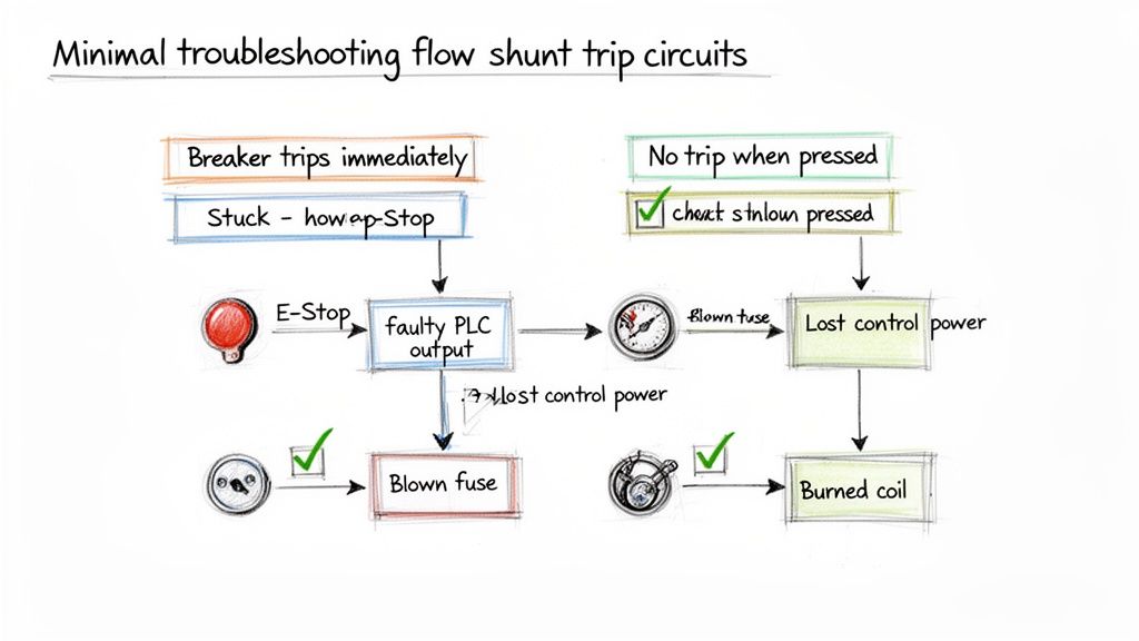
Symptom One: The Breaker Trips Immediately on Reset
This is a classic. You go to close the breaker handle, and click—it immediately snaps back open. This almost always points to an active trip signal. The shunt coil is getting power the instant you try to reset the breaker.
The cause is rarely the breaker itself. More often than not, the initiating device is stuck in the "closed" or "tripped" position, continuously sending voltage right to the coil.
Here’s where to start your investigation:
Check the E-Stop Button: Is a mushroom-head E-stop actually pulled out to its reset position? I can't count how many times I've seen a button still latched in from a previous test or bump.
Inspect PLC Outputs: If a PLC is running the show, you need to look at the logic and the status of the output relay. A sticky relay or a simple programming error could be holding that contact closed.
Look for Shorted Wires: It’s less common, but the control wires going to the shunt coil could be shorted together somewhere. This effectively bypasses the initiating device and sends constant power straight to the coil.
Troubleshooting Takeaway: An immediate re-trip means your control circuit is "live." The problem isn't the breaker failing; it's the trip signal never turning off. Focus your energy on whatever is sending that signal.
Symptom Two: The Trip Button Does Nothing
The complete opposite problem is just as common: you slam the E-stop button, and… nothing. The breaker stays closed, and the equipment keeps humming along. This tells you there's a break somewhere in your control circuit, preventing voltage from ever reaching that shunt coil.
When you hit this wall, think of it as tracing a path of electricity and finding where it dead-ends.
A Logical Diagnostic Path:
Verify Control Power: Is the control circuit even on? Grab your multimeter and confirm you have the proper voltage (e.g., 120V AC or 24V DC) at the source. It’s a dead-simple first step that often ends the search right there.
Check the Control Fuse: This is the number one culprit, hands down. A blown fuse in the control circuit will kill power to the entire trip system. Always keep spares in your bag.
Test the Initiating Device: With the power off, switch your meter to continuity and test the E-stop or relay contact. Does it show a closed circuit when you press the button? Contacts wear out and fail. It happens.
Inspect the Shunt Coil: If you confirm power is reaching the coil terminals when the button is pressed but the breaker isn't tripping, the coil itself is likely toast. You can test its resistance (with power off, of course) and check it against the manufacturer’s spec sheet.
Common Questions About Wiring a Shunt Trip Breaker
Even with a perfect diagram, wiring up a shunt trip breaker for the first time can bring up a few questions. Let's walk through some of the most common sticking points I see in the field to make sure your installation is safe and works the first time.
Can a Shunt Trip Coil Stay Energized?
Absolutely not. If you remember only one thing, make it this: a shunt trip coil is built for momentary duty only. Think of it like the starter in your car—it just needs a quick jolt of voltage to do its job.
Leaving constant power on the coil is a surefire way to burn it out, and it happens fast. We're talking a matter of minutes. That's why your control device, whether it's an E-stop button or a relay, must use a normally open (N.O.) contact that only closes for the brief moment you need to trip the breaker.
What Happens If I Use the Wrong Voltage on the Coil?
Using the wrong voltage is a recipe for failure, simple as that. The results are predictable, and neither is good.
Under-voltage: If you send 24V DC to a 120V AC coil, for example, you won't get enough magnetic force to trip the breaker. The coil just won't have the muscle to work the internal mechanism. Your safety circuit will be completely useless.
Over-voltage: This is even more dramatic. Hooking up 120V AC to a 24V DC coil will cause it to instantly overheat and fry itself. You'll get a puff of smoke, a dead coil, and maybe even a damaged breaker.
Before you land a single wire, double-check the voltage rating printed right on the shunt trip accessory against your control circuit's power source. It's a five-second check that prevents a costly headache.
Is a Separate Fuse for the Shunt Trip Circuit Necessary?
Yes, and it's not optional. The control circuit for the shunt trip needs its own dedicated overcurrent protection, usually a small fuse or a miniature circuit breaker. This little fuse is there to protect the control wiring and the coil itself if a short circuit ever happens.
Without that fuse, a fault in your control wiring could become a fire hazard or take down your entire control power supply. Sizing is crucial here. You need a fuse rated to handle the coil's quick inrush of current without popping, but small enough to blow instantly on a real fault. Check the manufacturer's spec sheet, but you're typically looking for something between 0.5A and 2A.
Can I Add a Shunt Trip to Any Circuit Breaker?
Nope. Shunt trip accessories aren't a universal, one-size-fits-all part. The circuit breaker itself has to be designed from the factory to accept a shunt trip module. These specific breakers have the necessary internal linkages and mounting slots for the accessory to physically connect and operate.
Trying to force a shunt trip into a standard breaker that wasn't made for it is just not going to work and is completely unsafe. Always confirm your breaker's model number can take a shunt trip by checking its technical documents before you buy anything.
Thankfully, finding compatible components is getting easier. The global market for these accessories was around USD 1.1 billion in 2024 and is expected to double by 2033, thanks to a huge push for better industrial safety and automation. This growth means better availability and clearer documentation from manufacturers. You can dig into this market trend over on Verified Market Reports.
What Is the Difference Between a Shunt Trip and an Undervoltage Release?
I hear this one all the time. It's easy to get them mixed up, but they do the exact opposite job.
Shunt Trip (ST): This trips the breaker when you apply voltage to it. Think of it as an active, "trip on command" device. It's what you need for E-stops and remote shutdowns.
Undervoltage Release (UVR): This trips the breaker when voltage is lost or dips too low. It needs constant power to hold the breaker closed. This is used to prevent equipment from unexpectedly restarting after a power failure.
Choosing the right one is all about the safety function you're trying to achieve. If it's an emergency stop, you always want a shunt trip.
At E & I Sales, we specialize in providing correctly specified UL-listed control solutions, including pre-wired and tested shunt trip circuits that eliminate guesswork and ensure your systems meet the highest safety standards. For expert guidance on your next project, visit us at https://eandisales.com.
A ground fault test is one of the most important diagnostic tools in your arsenal. It’s how you verify that your electrical insulation is solid and that your safety systems are actually ready to detect dangerous stray currents. This isn't just about ticking a box for compliance; it's often the single most important step in tracking down those maddening intermittent trips and preventing a serious shock or fire.
Why a Ground Fault Test Is Your First Line of Defense
When a machine starts tripping intermittently, the first instinct for many is to start swapping parts—a new breaker here, a different drive there. More often than not, this shotgun approach completely misses the real culprit: a ground fault.
This happens when electrical current leaks out and finds an unintended path to ground. Think of worn insulation on a motor lead rubbing against the inside of a metal conduit. This creates a severe, hidden hazard for both your people and the equipment itself.
The Real Danger of a "Slow Leak"
It’s easy to confuse ground faults with short circuits, but they behave very differently. A short circuit is like a head-on collision—two conductors touch, creating a massive, instantaneous current spike that trips a standard breaker immediately. A ground fault, on the other hand, is more like a slow, dangerous leak.
A small amount of current escapes its intended path. It might not be enough to trip a standard overcurrent device, but it's more than enough to deliver a fatal shock.
The true danger is how subtle it can be. Because the fault current is often low, the equipment might keep trying to run, even while its entire metal frame is dangerously energized. Performing a ground fault test is how you find this hidden killer before it causes a catastrophic failure or, worse, a serious injury.
What You Gain From Regular Testing
Making ground fault testing a routine part of your preventative maintenance is fundamental to keeping an electrical system reliable and safe. It helps you:
Prevent Unscheduled Downtime: Finding insulation breakdown early lets you schedule a repair on your own terms, not in the middle of a critical production run.
Protect Expensive Assets: A nagging ground fault can cook the windings on motors and transformers or fry sensitive electronics in control panels.
Ensure Personnel Safety: This is the big one. An undetected ground fault turns a machine into a ticking time bomb. It’s also important to understand broader safety protocols, like the battery and fire-safety considerations for homes and facilities with energy storage systems.
A proactive approach to ground fault testing shifts your entire maintenance posture from a reactive, stressful cycle to a controlled, preventative strategy. It’s the difference between finding a small problem during a planned outage and discovering a major failure during peak production.
Ground Fault vs Short Circuit At a Glance
To be an effective troubleshooter, you need to know the difference between these two common faults. This table breaks it down.
Characteristic
Ground Fault
Short Circuit
Current Path
From a "hot" conductor to an equipment grounding conductor, metal frame, or conduit.
Directly between two or more "hot" conductors (phase-to-phase) or between a hot and a neutral.
Current Level
Can be very low (milliamps) or high, but often below the trip rating of a standard circuit breaker.
Extremely high, typically hundreds or thousands of amps, causing an immediate overcurrent trip.
Primary Hazard
Electric shock. The equipment frame can become energized without any obvious signs of a problem.
Fire and arc flash. The massive energy release can cause explosions and fires.
Knowing which fault you're likely dealing with points you to the right diagnostic tools and safety precautions from the start.
The need for this kind of specialized detection isn't new; engineers have been working on this since the early 20th century. A deeper understanding of modern ground fault protection principles will make your testing and troubleshooting that much more effective.
Assembling Your Toolkit and Safety Gear
Trying to run a ground fault test without the right prep is more than just inefficient—it’s how accidents happen. This is your pre-flight checklist. Success starts long before you ever hook up a test lead, kicking off with a serious commitment to safety and having the right diagnostic gear in hand.
This isn't about just grabbing any old pair of gloves from the truck. Every piece of Personal Protective Equipment (PPE) is your last line of defense against thousands of volts. One simple slip-up can have life-altering consequences, which makes having the right gear absolutely non-negotiable.
Your Non-Negotiable Safety Kit
Before you even think about opening a cabinet, you need to be wearing the right armor. The specific level of PPE you need is determined by an arc flash hazard analysis, but for any industrial ground fault testing, your baseline kit must include:
Voltage-Rated Gloves with Leather Protectors: These are your first and best defense against electric shock. Always, and I mean always, inspect them for pinholes by rolling them up and trapping air inside before each use.
Arc-Rated Clothing or Suit: Your standard work clothes will do absolutely nothing to protect you from the searing heat of an arc flash. Proper FR/AR gear is designed to self-extinguish and can be the difference between a close call and a catastrophic injury.
Safety Glasses and Arc Flash Hood/Face Shield: You only get one set of eyes. An arc flash throws off blindingly bright light and a spray of molten metal, making this protection critical.
Insulated Tools: While they're no substitute for a proper lockout, using tools with a 1000V insulation rating adds a vital layer of protection from an accidental slip.
A quick reminder from the field: PPE doesn't make you invincible. It just gives you a fighting chance if things go sideways. It only works if you use it correctly and keep it in good condition.
Essential Diagnostic Instruments
Once you're geared up for safety, it's time to grab the right tools for the diagnosis. Your standard multimeter is great for quick voltage checks, but it’s the wrong tool for this job. For a real ground fault test, you need specialized equipment.
These are your two workhorses:
Insulation Resistance Tester (Megohmmeter): This is your go-to for checking the health of motor windings and cable insulation. It applies a high DC voltage—typically 500V or 1000V—to stress the insulation and measures the resistance in megohms (MΩ). A low reading means you likely have a leakage path to ground.
Ground Fault Relay Test Set: This device is for testing the protection system itself. It injects a simulated fault current through the system's current transformer (CT) to prove the ground fault relay trips at the right current setting and within the specified time. This is how you confirm the whole system—sensor, relay, and breaker—is working together as it should.
Executing a Lockout/Tagout Procedure
No testing begins until that equipment is at a zero-energy state. A methodical Lockout/Tagout (LOTO) procedure is the only way to be sure.
Let’s walk through a common scenario: isolating a bucket in a 480V Motor Control Center (MCC).
Scenario: Isolating MCC Bucket #7 for a Motor Ground Fault Test
Everything starts with clear communication. Make sure everyone working in the area knows what's about to happen.
The qualified electrician performing the work will then:
Identify the Source: Positively identify the disconnect handle for Bucket #7. Double-check the label.
De-energize: Firmly rack out the bucket or throw the disconnect to the "OFF" position.
Apply Lock and Tag: Place your personal lock and tag on the disconnect. Your tag needs your name, the date, and why it's locked out. And remember, no one else should ever have a key to your lock.
Verify Zero Energy: This is the most crucial step. Using a properly rated multimeter, you have to perform a live-dead-live test. First, test your meter on a known live source to prove it works. Next, test for voltage on the load-side terminals of the bucket (phase-to-phase and each phase-to-ground). Finally, go back and re-test your meter on that same known live source.
Only after you've confirmed zero volts is it safe to proceed. This process guarantees that the circuit can't be re-energized while you’re in the middle of your test.
Testing Insulation Resistance on Motors and Cables
When you're staring down a suspected ground fault, all the theory in the world takes a backseat to what you can prove with a meter in your hand. This is where the insulation resistance test—what most of us in the field just call a "megger" test—becomes your best friend. It’s the single most effective way to get a real health check on a motor’s windings or a run of cable before a nagging problem turns into a catastrophic failure.
Let's put this into a real-world context. Imagine you've got a three-phase, 480V motor that keeps tripping. You’ve done your Lockout/Tagout, you’ve verified zero energy, and now it's time to find out what's really going on.
The Motor Test Procedure
The tool for this job is an insulation resistance tester, or megohmmeter. The whole point of the test is to push a specific DC voltage into the motor's windings and measure how much of that current "leaks" through the insulation to the grounded frame of the motor. A high resistance reading means healthy insulation. A low reading? That’s your red flag.
First things first, you have to get the motor completely on its own. It's not enough to just lock out the breaker; you need to physically disconnect the motor leads from the starter or VFD. We need to test the motor by itself, not the whole circuit.
Once you're at the motor's junction box (the peckerhead), here’s the game plan:
Pop open the cover and disconnect the incoming T1, T2, and T3 leads from the motor's own leads.
Make absolutely sure the motor leads are spread apart, not touching each other or any part of the metal housing.
Clip one lead from your megohmmeter right onto the motor's frame. Find a clean, unpainted bolt head—that makes a perfect ground reference.
Take your other test lead and connect it to all three motor windings (T1, T2, and T3) at the same time. A few alligator clips make it easy to jumper them all together for this part of the test.
With this setup, you're checking the integrity of the entire winding assembly against its grounded enclosure. You're hunting for any sneaky path electricity might be taking to ground where it shouldn't be.
Selecting the Right Test Voltage
Picking the right voltage on your megger is crucial. Go too high, and you risk damaging perfectly good insulation. Go too low, and you won’t put enough stress on it to reveal a hidden weakness.
A good rule of thumb is to test at about double the circuit's operating voltage, but we stick to standard practices:
For 480V or 600V systems, you’ll almost always use the 1000V DC setting.
For smaller circuits under 250V, a 500V DC test is the way to go.
For our 480V motor, set the meter to 1000V DC and hit the test button. You need to hold it for a full 60 seconds. You'll likely see the resistance reading climb as the windings get charged up—that's normal. The number you care about is the final, steady reading at the one-minute mark.
So, what’s a "good" number? While standards from groups like NETA give you the official specs, a reliable field rule is 1 megohm per kV of the motor's rating, plus another 1 megohm. For a 480V (0.48kV) motor, that means anything over 1.5 MΩ is generally considered a pass. Honestly, though, a healthy modern motor should give you a reading way up in the hundreds or even thousands of megohms.
Applying the Same Logic to Power Cables
If the motor tests out clean, your next suspect is the cable feeding it. Thankfully, the process is pretty much the same. With the cable disconnected on both ends (at the MCC and the motor), you’ll test the insulation of each conductor.
Here's how you break down the cable test:
Phase-to-Ground: Test each conductor one by one. Hook one meter lead to the ground wire or conduit, then test Phase A, then Phase B, then Phase C with the other lead.
Phase-to-Phase: Now, check for shorts between the conductors themselves. Test A-to-B, B-to-C, and finally A-to-C.
This thorough check confirms the cable's integrity from end to end. If you get a low reading here, you're likely dealing with insulation that's been pinched in a conduit, damaged by moisture, or just cooked from years of heat. Diving deeper into these scenarios is key, which is why we put together a guide on the protection of motors that covers more ground.
This kind of hands-on insulation testing is so important because many ground faults, especially high-impedance faults (HIFs), simply don't draw enough current to trip a standard breaker. Research has shown a 240V fault through just 1 kΩ of resistance only produces about 240 mA of current—nowhere near enough for most overcurrent devices to even notice. That's why a megohmmeter is the only tool that can reliably sniff out these dangerous, hidden faults before they cause real damage.
How to Performance Test Your Protection System
An insulation resistance test is a great diagnostic tool. It tells you a lot about the health of individual components, like motor windings or cables. But here’s what it doesn't do: it doesn't prove that your entire safety system—the relay, the sensor, and the breaker—will actually work together to clear a fault when it matters most.
That's where a true performance ground fault test comes in. This is the crucial step that moves beyond checking component health to verifying total system function.
This isn’t just a nice-to-have; it's a code requirement. According to NEC Section 230‑95, every ground‑fault protective device must be performance-tested when it's first installed on-site. You also need a written record of that test available for the authority having jurisdiction (AHJ). The code is specific, calling for injected current tests—not just a quick push-button check—to verify the system's actual pickup current and trip time.
The general process follows a simple, methodical flow: safely isolate the equipment, run the test, and then analyze the results to make an informed decision.
This visual really drives home the core steps. You always start by disconnecting and verifying a zero-energy state. Only then do you apply the test, and finally, you interpret the data you've gathered.
Choosing the Right Ground Fault Test Method
There are a few ways to approach ground fault testing, and picking the right one depends on what you need to verify. Each method has its place, offering a different level of assurance.
This table breaks down the common methods to help you understand their best applications, what they can tell you, and just as importantly, what they can't.
Test Method
Primary Application
Pros
Cons
Push-to-Test Button
Simple go/no-go verification of the relay and trip coil.
Quick and easy; requires no special equipment.
Doesn't test the CT or wiring; doesn't verify pickup or timing accuracy.
Secondary Injection
Verifies relay pickup settings and timing curves.
Highly accurate for testing the relay's logic and calibration.
Bypasses the main current transformer (CT) and its wiring.
Primary Injection
Full system performance test, from the CT to the breaker.
Tests the entire protection chain; the most comprehensive and reliable method.
Requires specialized high-current test set; more time-consuming to set up.
While a push-to-test is a decent spot check, the primary injection method is the gold standard for commissioning and thorough maintenance because it leaves no part of the system unverified.
Setting Up for Primary Current Injection
We're going to focus on the primary injection method because it’s the most thorough way to test a ground fault protection relay in switchgear. This technique uses a high-current test set to push a simulated fault current right through the system's zero-sequence current transformer (CT). It’s the only way to test the entire chain of command, from the CT's ability to sense the fault to the relay's logic and the breaker's physical trip mechanism.
First thing's first: safety. Completely isolate the circuit breaker or switchgear section you're testing. Meticulously follow your LOTO procedure, making sure the equipment is de-energized and verified at a zero-energy state. You'll be working with a test set that can produce thousands of amps, so there's no room for error.
Once the equipment is safely isolated, it's time to connect the high-current test set. The connections are fairly simple but demand precision.
Connect the high-current output leads from your test set so they pass directly through the window of the zero-sequence CT.
The timer input leads from your test set will connect to the breaker’s auxiliary contacts. This is how the test set automatically records the time it takes for the breaker to open after the relay issues its trip command.
This setup creates a controlled, closed loop that perfectly mimics a real-world ground fault, letting you measure the system's actual response.
Calculating Your Test Parameters
Before you inject a single amp, you need to know what you're looking for. The target values for your test are right there on the ground fault relay itself—either on the faceplate dials or within its programming file. You need to find two key settings: the pickup current and the time delay.
Let's walk through a common scenario. Imagine a relay is set for a 100A pickup with a time delay of 0.1 seconds (100 milliseconds).
With these settings, your test needs to verify two things:
Pickup: What is the minimum current that makes the relay operate?
Timing: How long does it take for the breaker to trip at a specific, higher fault current (usually 300% of the pickup setting)?
To check the pickup value, you’ll start injecting current well below the 100A setting and slowly ramp it up. The exact amperage where the relay's "pickup" light comes on is your measured value. It should be right on the money, very close to that 100A setting.
Executing the Test and Verifying Trip Time
Once you've confirmed the pickup value, it's time to check the trip time. This is where you test the system’s reaction speed. Based on the coordination settings, you’ll inject a higher current—a standard practice is to use three times the pickup setting—to simulate a more serious fault.
In our example, that means injecting 300A.
The test set will apply 300A and start its timer at the same instant. The moment the breaker trips, its auxiliary contacts open, which stops the timer. The time displayed is your measured trip time. For our relay set to 0.1 seconds, seeing a result between 95-105 milliseconds would be a solid pass.
The real value of this test is in the data. Documenting the "as-found" settings, the measured pickup current, and the measured trip time creates a baseline for all future maintenance. This record is your proof of compliance and your best tool for tracking the health of your protection system over time.
By comparing these real-world results to the manufacturer's specs and your own coordination study, you'll know everything you need to. If the values are within tolerance, your system is good to go. If not, it's time to start troubleshooting the relay, CT, or breaker before that circuit goes back into service.
Interpreting Results and Troubleshooting Faults
A failed ground fault test isn't a dead end—it's a signpost pointing you toward the real problem. The readings on your meter are clues, and learning how to interpret them is what separates a parts-swapper from a true diagnostician. A low megohm reading or a relay that won't trip is simply the start of a logical troubleshooting process.
This is where you put on your detective hat. The key is to isolate variables systematically. Don’t just assume; prove it with your meter. By breaking a circuit down into its individual components—the cable, the motor, the switchgear—you can pinpoint the exact location of the failure without any guesswork.
The Divide and Conquer Strategy
Let's walk through a common scenario. You run an insulation resistance test on a motor circuit and get a dismal 0.5 MΩ reading. It’s a clear failure. Panic doesn't fix anything, but a solid plan will. The first question is always the simplest: is the problem in the wiring or in the motor itself?
To find out, you need to split the circuit. Get down to the motor's junction box, disconnect the motor leads from the incoming power cable, and then test each piece on its own.
Test the Cable First: With the motor completely out of the circuit, perform the same phase-to-ground insulation test on just the cable. If that reading is still low, you know the fault is somewhere between the starter and the motor j-box.
Then Test the Motor: If the cable tests perfectly (showing hundreds or even thousands of megohms), the fault is almost certainly inside the motor windings.
This simple "divide and conquer" method can save you countless hours of frustration. You've just narrowed a potentially facility-wide headache down to either a specific cable run or a single piece of equipment.
Common Culprits Behind Low Insulation Readings
When an insulation test fails, the root cause is usually some kind of physical damage or contamination. Insulation doesn't just decide to fail on its own; something external causes it to break down.
Here are the usual suspects I look for first:
Moisture Intrusion: Water is electricity’s worst enemy, hands down. A flooded conduit, a leaky seal on a motor peckerhead, or condensation inside a panel are all frequent sources of ground faults.
Heat Damage: Over time, excessive heat from an overloaded motor or just high ambient temperatures can cook insulation until it's brittle. Once it cracks, you've got a ready-made path to ground.
Physical Damage: This is incredibly common, especially during installation. A cable jacket gets nicked while being pulled through a tight conduit, or constant vibration causes a wire to rub against a sharp metal edge inside a panel.
Contamination: In dirty industrial environments, conductive dust from metal grinding or other processes can build up inside equipment, creating a low-resistance path where there shouldn't be one.
A failed test result is just data. The real skill is connecting that data to a physical cause. An intermittent fault that only pops up on rainy days, for instance, is a huge clue that you should be hunting for moisture.
Troubleshooting Failed Relay Performance Tests
So what happens if your insulation tests pass with flying colors, but the ground fault relay itself fails its performance test? This tells you the issue is within the protection system, not the power circuit. If that relay trips too soon, too late, or not at all, your focus needs to shift from insulation to instrumentation.
First things first, double-check the obvious. Are the relay settings correct according to the coordination study? It’s surprisingly common to find that someone programmed the wrong pickup or time delay settings into the device.
If the settings are right, the problem likely lies in the sensing circuit.
Check the CT Wiring: A loose or incorrect connection at the zero-sequence current transformer (CT) is a classic culprit. The relay can't react to a fault it can't see.
Inspect the CT Itself: While rare, current transformers can fail. A damaged or shorted CT simply won't produce the correct secondary current needed to operate the relay.
Understanding these failure modes is crucial for building a complete picture of electrical safety. Sometimes, a persistent ground fault can also be a symptom of a larger issue, which is why it's helpful to understand the various reasons what can cause a breaker to trip beyond a simple fault. After you diagnose and repair the root cause, always re-run your ground fault test to verify the fix before you even think about re-energizing the equipment.
Got Questions About Ground Fault Testing? We've Got Answers.
Even for seasoned pros, a few questions always seem to come up out in the field. Ground fault testing can feel complicated, but once you nail down a few key concepts, you'll have the confidence to get it done right—and safely—every time.
Let's dig into some of the most common questions we hear from technicians and engineers on the floor.
How Often Should I Be Running a Ground Fault Test?
There’s no single, universal answer here. How often you test really boils down to your specific compliance needs and the kind of environment your equipment lives in. But we can map out some solid guidelines that cover most industrial scenarios.
For anything brand new, the rules are black and white. The National Electrical Code (NEC) requires a full performance test on any new ground fault protection system right after it's installed. After that, it becomes a part of your regular preventative maintenance cycle.
For Compliance: The NEC mandates a performance test on initial installation. No exceptions.
For General Maintenance: Following NETA standards is a great baseline. They recommend comprehensive testing every one to three years for most gear.
For Harsh Environments: If your facility deals with high moisture, constant vibration, or conductive dust, don't wait three years. Testing your critical motors and switchgear annually is a smart move that prevents nasty surprises.
What's the Difference Between a GFCI Test and a Ground Fault System Test?
This is a great question because it gets to the heart of a major difference in scale and purpose. They both involve "ground faults," but they are protecting completely different things at wildly different levels.
A GFCI test is a simple life-safety check for a single device, like an outlet near a sink. When you push that little "Test" button, you're just making sure its internal trip mechanism works at a very low leakage current—we're talking just 4-6 milliamperes (mA). It’s all about protecting a person from getting a dangerous shock.
A ground fault system test, on the other hand, is a full-blown diagnostic for your industrial power system. This is a much bigger deal, requiring a proper lockout/tagout and specialized gear like megohmmeters and high-current test sets. The goal here is to confirm the insulation on motors and cables is solid and to prove that your big protective relays will actually trip under massive fault currents to prevent catastrophic equipment damage and fires.
Here’s a simple way to think about it: A GFCI test is like checking the smoke detector in your kitchen. A ground fault system test is like the fire department coming out to test the hydrants and sprinklers for the whole industrial park. Both are critical, but they operate on totally different scales.
Can I Just Use a Multimeter for a Ground Fault Test?
Absolutely not. This is one of the most common and dangerous mistakes we see people make. A standard multimeter is simply the wrong tool for this job; it can't give you the information you actually need.
Your multimeter uses a tiny voltage—maybe just a few volts—to check for things like continuity. It’s perfect for telling you if a fuse is blown, but it's useless for stress-testing insulation. The problem is, insulation often only breaks down when it's hit with a voltage close to what it sees during normal operation.
To do a real ground fault test, you need a proper insulation resistance tester, which most of us just call a megohmmeter. This tool doesn't mess around. It applies a high DC voltage, typically 500V or 1000V, to the conductor. That's enough to properly stress the insulation and reveal any hidden weak spots or leakage paths a multimeter would miss a hundred times out of a hundred. The result is a reading in megohms (MΩ), which is the only true measure of insulation health.
At E & I Sales, we've been designing, building, and troubleshooting complex industrial electrical systems since 1974. Whether you need rock-solid UL-listed control panels, premium motors, or expert system integration, our team has the hands-on experience to deliver the right solution. See how our expertise can power your next project at https://eandisales.com.
Let's be blunt—an arc flash isn't just a spark. It's a violent, catastrophic failure with devastating human and financial costs. A structured arc flash safety training program isn't just about checking a compliance box; it’s about building a safety culture that actively prevents injuries, sidesteps crippling fines, and protects your entire operation.
Why a Proactive Safety Culture Is Non-Negotiable
It’s easy to get lost in the textbook definitions, but the reality is much harsher. An arc flash is a brutal explosion of energy, capable of reaching temperatures hotter than the surface of the sun in a split second. The consequences are immediate and often horrific. That’s why a rock-solid safety program is an absolute necessity, not an optional line item in the budget.
The numbers don't lie. We see roughly 30,000 arc flash incidents in the U.S. every single year. These aren't minor events; they lead to around 7,000 burn injuries, 2,000 hospitalizations, and 400 fatalities annually. As these arc flash accident statistics from AllumiaX show, electrical hazards are a constant, lurking threat in any industrial setting.
The Real Price of an Incident
When an arc flash happens, the fallout goes way beyond the initial medical response. The financial gut punch to a business can be staggering, hitting you from all sides with both direct and indirect costs.
Hefty OSHA Fines: We're not talking about a slap on the wrist. Non-compliance penalties can easily soar into the hundreds of thousands of dollars.
Crushing Medical Bills: Treating severe, life-altering burns is incredibly expensive, often running into the millions for just one person.
Destroyed Equipment: That explosive force can obliterate expensive switchgear, control panels, and other vital infrastructure in an instant.
Crippling Downtime: While you’re dealing with the investigation and repairs, production grinds to a halt, and every minute is lost revenue.
A proactive safety culture, anchored by consistent and effective training, is your best—and really, your only—defense. It’s about shifting the entire company mindset from reactive damage control to proactive, intelligent prevention.
A truly effective safety culture is one where every employee, from the shop floor to the C-suite, understands not just what they need to do, but why it's so critical. It’s the difference between a checklist mentality and a shared commitment to keeping everyone safe.
The Core of an Effective Program
Building this kind of culture isn't magic; it's a structured approach. To get there, you need to focus on a few key pillars that work together. A great safety program isn't just one thing, but a combination of interlocking components.
Let's break down what that looks like.
Core Components of an Effective Arc Flash Safety Program
Pillar
Objective
Key Activities
Realistic Risk Assessment
Identify and quantify hazards.
Incident energy analysis, defining arc flash boundaries, proper equipment labeling.
Clear Safety Procedures
Create unambiguous, actionable rules.
Lockout/Tagout (LOTO), energized work permits, proper tool selection and use.
Ongoing Education & Training
Ensure knowledge is current and practical.
Hands-on drills, regular refreshers, competency checks, PPE demonstrations.
This table provides a high-level view, but the real work is in the details and the commitment to consistency.
A one-and-done training session just won't cut it. Real safety comes from continuous education that keeps knowledge fresh and skills sharp, especially as standards or equipment change. A smart move is to weave this training into your regular operations. For instance, you can formalize your commitment by integrating safety checks and training reminders right into a preventive maintenance schedule template.
Ultimately, putting money and effort into a comprehensive arc flash safety program is a direct investment in your people, your productivity, and your company's long-term health. It shows you're serious about safety as a core value, not just an obligation.
Getting to Grips with the Rules and Standards
When you first dive into electrical safety, the acronyms can feel like alphabet soup. OSHA, NFPA, NEC… what does it all mean? These aren't just bureaucratic hurdles; they're the bedrock of any serious arc flash safety training program. Understanding them is what keeps people from getting hurt.
The two big players you absolutely have to know are OSHA (Occupational Safety and Health Administration) and NFPA (National Fire Protection Association).
Think of it like this: OSHA writes the law. They set the legal requirement—the "what"—for providing a safe workplace. NFPA, especially through its NFPA 70E standard, gives you the "how." It's the industry's consensus on the best practices to actually achieve that safety.
An OSHA inspector won't write you a ticket for an NFPA 70E violation directly. But they will cite you under their General Duty Clause for failing to protect employees from known hazards. And guess what they use as the yardstick for what's considered "safe"? You guessed it: NFPA 70E.
Putting the Core Concepts to Work
To make these standards work on the plant floor, you need to speak the language. The regulations are built on a few critical ideas that have to be baked into your training and your everyday work.
Qualified Person: This isn't just a job title. A "qualified person" is someone who has been specifically trained on the equipment, its operation, and the hazards involved. Crucially, they have to demonstrate they have the skills to work safely near live parts.
Arc Flash Boundary: This is a non-negotiable safety perimeter. Inside this boundary, an unprotected worker could get a second-degree burn if an arc flash kicks off. Your training has to hammer this home: crossing that line without the right PPE is a hard stop. No exceptions.
Incident Energy: This is the raw power of an arc flash, measured in calories per square centimeter (cal/cm²). It's the amount of heat your body would take at a set distance. That number, right there on your equipment labels, tells you exactly what level of arc-rated PPE is required to do the job.
I remember a case at a facility where an experienced electrician—a great mechanic, but not formally "qualified" by OSHA's definition—was troubleshooting a 480V panel. He triggered an arc flash and got badly burned because he wasn't wearing PPE rated for the calculated incident energy. The investigation found that his training was never documented and the arc flash boundary was ignored. It was a painful, expensive lesson in why these definitions matter.
The standards aren't just rules to memorize; they are life-saving tools. When your team understands that 'incident energy' isn't an abstract number but a direct measure of potential harm, their entire approach to safety changes.
The Big Picture: Global Standards and Why They Matter
This focus on rock-solid training isn't just a U.S. thing. The global market for arc flash protection is driven by these kinds of regulatory frameworks. North America was the biggest market in 2023, mostly because of strict standards from agencies like OSHA and Canada's CSA that demand comprehensive safety programs, including worker training. You can dig into the numbers yourself and check out these arc flash protection market trends from Grand View Research.
This worldwide push proves a simple truth: strong standards and consistent enforcement create demand for better equipment and more thorough training. It also circles back to how your facility's systems are designed in the first place. For instance, a smart industrial control panel design can engineer out some of the arc flash risks from the get-go, making it much easier to stay compliant and keep everyone safe.
At the end of the day, truly understanding these regulations turns your safety program from a chore into a strategy. It gives your team the power to not just follow rules, but to take ownership of their safety because they get the physics and the real-world risks behind every single task. That knowledge is the real foundation of a safety culture that actually works.
Mastering Arc Flash Risk Assessments and Labeling
Think of an arc flash risk assessment as the foundation of your entire electrical safety program. This isn't just about checking a box on a compliance form; it's the detailed engineering study that turns abstract electrical hazards into concrete, life-saving information for your team on the floor. It’s what quantifies the specific dangers lurking inside every panel and piece of equipment.
To do this right, you have to conduct a meticulous data collection process—basically an electrical census of your entire facility. Engineers need to dig into the details of every component, from the main utility feed all the way down to the individual circuit breakers. This means gathering precise data on fault current levels, conductor sizes and lengths, and, most importantly, the trip times of all your protective devices.
In-House Team Versus Third-Party Experts
So, who tackles this critical analysis? That's one of the first big decisions you'll make.
You might be tempted to use your in-house engineering team to save some money, but it's often not that simple. These studies require highly specialized software and a deep, nuanced understanding of standards that can be a real hurdle for a team that doesn't live and breathe this stuff every day.
This is where third-party engineering firms really shine. They perform these studies day in and day out, bringing an unbiased, expert perspective to the table. They’ve seen it all across countless facilities and can often spot potential issues your internal team might miss. Their entire focus is on the accuracy and compliance of the study, making sure it aligns perfectly with NFPA 70E and OSHA. That independent verification is worth its weight in gold, especially if an auditor comes knocking.
Getting this right involves a clear path: you start with the standards, build out your training based on them, and then you achieve a true state of operational safety.
This visual really drives home how each step builds on the last. You can't have real safety without proper training, and you can't have proper training without first understanding the standards. It's a chain of compliance you can't break.
From Technical Data to Actionable Labels
All that complex engineering work boils down to one thing: the arc flash label. This is arguably the most important piece of safety communication you can have on your plant floor. It’s not just a warning sticker; it's a data-driven instruction manual for anyone interacting with that equipment. A solid arc flash safety training program has to teach every qualified worker how to read, understand, and act on these labels in a split second.
A compliant label needs to spell out a few critical pieces of information:
Incident Energy: This is the big one, shown in cal/cm². It tells you the minimum Arc Thermal Performance Value (ATPV) your PPE needs. If the label says 8.5 cal/cm², your gear better be rated higher than that.
Arc Flash Boundary: This is the "stay-out" zone. It’s the closest an unprotected worker can get before risking a second-degree burn. No one crosses that line without the right PPE on.
Required PPE Category: While modern labels often list specific gear, you'll still see the category method (1, 2, 3, or 4). Each number corresponds to a pre-defined kit of protective clothing and equipment.
Shock Risk Information: This includes the nominal system voltage and the approach boundaries (limited and restricted), which are absolutely critical for preventing shock.
The arc flash label is the final translation of complex engineering into a simple, non-negotiable set of instructions. When a worker sees that label, they should know in seconds exactly what it takes to work on that piece of equipment without getting hurt.
Let’s make this real. Say you have a 480V motor control center with a label showing 12 cal/cm² incident energy and a 48-inch arc flash boundary. A properly trained employee knows instantly they need, at minimum, a 12-cal arc-rated suit, balaclava, and gloves before they can even think about crossing that four-foot perimeter. It completely removes the guesswork.
When you're sourcing PPE based on these assessments, you have to consider every single component. Even smaller items, like a Leather Cut Resistant Driver Glove With Arc Flash Rating, must meet the required protection levels.
All this label data comes from analyzing how your protective devices will operate during a fault. The faster a circuit breaker clears the fault, the lower the incident energy. That's why understanding the specific performance of your components is so vital. Knowing the details of an ABB circuit breaker, for instance, is just as important for the engineers running the study as it is for the technicians who maintain it.
Designing a Training Curriculum That Sticks
Let's be honest. A stale PowerPoint presentation and a box of donuts isn't an arc flash safety program. To really protect your team, you need a curriculum that builds active, life-saving skills—not one that just encourages passive listening. The end goal is to create muscle memory, making safe practices an automatic reflex, not just another item on a checklist.
A truly effective program is built from the ground up. It starts with the basics and layers on more complex, hands-on tasks. It's all about making sure every "qualified" worker understands the why behind the what, turning compliance rules into ingrained, safe work habits.
Foundational Knowledge Modules
Before anyone even thinks about touching a tool, they need a healthy respect for the invisible dangers they face. Your training has to start by demystifying the physics of electrical hazards in a way that actually connects with your team. This isn't about memorizing complex formulas; it's about building a deep-seated respect for the energy they work with every single day.
Your core modules have to cover these non-negotiables:
The Physics of Shock and Arc Flash: Clearly explain how a shock occurs—the path current takes through the body—and just how little amperage it takes to be fatal. For arc flash, break down the violent chain reaction: the short circuit through the air, the intense heat, the pressure wave, the molten shrapnel, and the blinding light.
Decoding Regulations and Labels: This is where the classroom meets the plant floor. Your team needs to know exactly how to read and interpret the arc flash labels on your equipment. They must understand what incident energy, boundaries, and specific PPE requirements mean for them right at that spot.
Recognizing Hazard Conditions: You need to train your team to be vigilant detectives. Teach them how to spot abnormal equipment conditions—subtle signs of arcing, overheating, corrosion, or physical damage—that can dramatically increase the risk of an incident.
Hands-On Skills and Practical Application
This is where the rubber really meets the road. Reading about safety is one thing, but practicing it is something else entirely. Interactive, hands-on sessions are absolutely essential for building the confidence and skills needed to work safely when the pressure is on.
Your curriculum has to include practical components. A fantastic example is a Lockout/Tagout (LOTO) simulation. Don't just show a slide; set up a training board with actual disconnects, breakers, and valves. Have your employees physically walk through the entire process of isolating, locking, and verifying a zero-energy state. This muscle memory is infinitely more valuable than just reading a procedure.
Another crucial hands-on session is PPE selection, inspection, and use. Get the gear out and have them practice:
Donning and Doffing: Walk them through the correct sequence for putting on and taking off a full arc flash suit, stressing how to avoid cross-contamination.
Glove Inspection: Teach them the proper technique for visually inspecting and air-testing their rubber insulating gloves before every single use.
Tool Selection: Show them the physical difference between standard and correctly rated insulated tools. Explain why that distinction is a matter of life and death.
A worker who has physically practiced the LOTO sequence and inflated their own gloves to check for pinholes is infinitely better prepared than one who has only watched a video. These hands-on drills are where safety theory becomes lifesaving reality.
Verifying a De-Energized State
If there's one skill that is the absolute most critical in any arc flash training program, it's learning how to properly use test instruments to verify an electrically safe work condition. This isn't a single step; it's a multi-step process that must be taught, demonstrated, and drilled until it's second nature.
The mantra is simple: Live-Dead-Live.
First, test your multimeter on a known live source to make sure it's working.
Second, test the target circuit phase-to-phase and phase-to-ground to verify zero voltage.
Finally, test your meter again on that same known live source to confirm it didn't fail mid-test.
This three-step procedure removes all doubt. It is the final, definitive confirmation that a circuit is safe to touch. Skipping any part of this sequence introduces a lethal amount of risk.
We know that improving these training programs relies on good data, but that data is often incomplete. Research from Johns Hopkins University highlighted a major gap between reported and actual electrical incidents. This underreporting makes it harder to refine safety protocols, underscoring the need for better data collection to create more effective training.
Making sure your team is ready for any electrical hazard means going beyond the basics. Comprehensive essential electrical safety training reinforces these crucial, hands-on verification techniques. A curriculum that sticks is one that creates a team that doesn't just know the rules, but has the practical skills to apply them every single day.
Keeping Your Safety Program Effective and Audit-Ready
Getting your arc flash safety training program off the ground is a major accomplishment. But the real work—the part that builds a lasting safety culture—starts the moment that first training session ends.
A program that’s just a binder on a shelf is useless when sparks fly, and it will absolutely fall apart under the microscope of an audit. We need to move away from a "one-and-done" mindset. Instead, think of it as a continuous cycle of reinforcement, skill verification, and obsessive record-keeping. This is about creating a living, breathing program that evolves with new standards, equipment changes, and your workforce.
Proving Competency Beyond the Classroom
So, did the training actually stick? You can't just assume that because someone sat through a PowerPoint, they absorbed the critical, life-saving details. You have to prove it.
A written exam is a decent first step. It’s great for checking their grasp of concepts like arc flash boundaries, incident energy, and the theory behind establishing an electrically safe work condition. But that only tells you what they know, not what they can do.
That’s where hands-on skill demonstrations are absolutely non-negotiable.
LOTO in Action: Can the employee walk up to a piece of machinery, correctly identify every single energy source, and properly apply their lock and tag?
Glove Inspection: Hand them a pair of rubber insulating gloves and ask for a pre-use inspection. Are they doing a proper air test? Can they spot the subtle signs of ozone damage, cuts, or pinholes?
The Live-Dead-Live Test: On a training panel, can they flawlessly execute the three-point check with a voltmeter to verify de-energization? This isn't just a step; it's a life-saving ritual.
This is the only way to be certain that head knowledge has become muscle memory.
Maintaining Defensible Documentation
Let's be blunt: in the eyes of an OSHA auditor, if you didn't document it, it never happened. Your records need to be clean, organized, and immediately accessible. A dusty sign-in sheet from a training three years ago isn't going to cut it. Your paperwork is your first and best line of defense.
For every qualified person on your team, you need an audit-ready file containing:
Training History: Dates, course topics covered, and the instructor's name.
Competency Proof: The actual written tests (with scores!) and the signed-off checklists from their hands-on skill demos.
Official Authorization: A formal document, signed by a manager, that officially designates them as a "qualified person" for specific electrical tasks.
An organized documentation system is more than just busy work; it's a clear, defensible narrative of your company's ongoing commitment to safety. It proves you not only train your people but also verify their skills and authorize their work responsibly.
The Critical Retraining Cycle
NFPA 70E is very clear on this: retraining on safe work practices must happen at intervals not to exceed three years. That’s not a random number. It’s a built-in recognition that skills get rusty, knowledge fades, and bad habits creep in.
Think about how much can change in three years—new equipment, updated standards, maybe even a few close calls. This refresher is your chance to close any gaps that have appeared. It's also the perfect opportunity to review recent near-misses (anonymously, of course) to drive the lessons home with real-world examples from your own facility.
Don't wait until the last minute. Get this on the calendar and into the budget now. A proactive refresh cycle ensures your arc flash safety training remains a dynamic part of your culture, not a forgotten event. This continuous loop—train, assess, document, repeat—is what keeps your people safe and your program ready for any scrutiny.
Common Questions About Arc Flash Training
Even with a solid plan, a few questions always seem to come up when you're dialing in an arc flash safety training program. We hear these all the time from safety managers and facility engineers. Here are the most common ones, with some practical answers to get you on the right track.
Who Really Needs This Training?
The short answer? Anyone who could be exposed to an electrical hazard. But it's not a one-size-fits-all deal. The kind of training they need depends entirely on what they do day-to-day.
OSHA and NFPA 70E split this into two clear groups:
Unqualified Persons: Think machine operators or janitorial staff. These folks work near electrical gear but not on it. Their training is all about hazard recognition—knowing what an arc flash label means, what the approach boundaries are, and who to call if something goes wrong. It's about empowering them to stay out of harm's way.
Qualified Persons: These are your electricians, maintenance techs, and engineers—the people diagnosing, troubleshooting, or working on equipment. Their training has to be deep and comprehensive, covering everything from risk assessment and LOTO to picking the right PPE and performing live-dead-live tests. They must be able to prove they have the hands-on skills to do the job safely.
What Does It Take to Be a "Qualified Person"?
This is a big one. A "qualified person" isn't just a title you give to someone with 20 years of experience. The standards are very clear: qualification is a formal designation given by the employer.
To be officially "qualified," a worker has to be trained on the specific hazards they'll face at your facility and must have demonstrated the skills and knowledge needed to protect themselves. This isn't a handshake agreement; it's a documented process.
That means you can't just hire a seasoned electrician and assume they're good to go. You are responsible for training them on your specific equipment, your documented safety procedures, and the findings from your facility's arc flash risk assessment. Qualification is always task-specific and has to be on the books.
How Often Do We Need to Retrain?
Skills get rusty, and it's easy for bad habits to sneak back in. That’s why NFPA 70E sets a hard deadline for retraining on safe work practices: at least every three years.
But think of that as a final safety net, not the goal. You'll want to retrain much sooner if you see unsafe practices during an audit, when an employee's job duties change, or whenever you bring in new equipment or technology. The three-year rule is the absolute maximum, not the recommended pace.
Can We Just Do All Our Training Online?
Online courses and a good Learning Management System (LMS) are fantastic for building foundational knowledge in arc flash safety training. But they can't do the whole job.
The "book smarts"—the physics of an arc flash, the details of the regulations, how to read an equipment label—are perfect for an e-learning format. It’s an incredibly efficient way to get consistent, baseline information out to your whole team.
The problem is, you can't verify the most important skills through a computer screen. There's just no way to know if a worker can properly inspect a pair of insulated gloves, execute a complex LOTO, or safely use a voltmeter without seeing them do it.
The best approach is a blended one. Use online modules for the theory, then bring everyone in for mandatory, in-person sessions to assess and verify their hands-on skills. You get the efficiency of digital learning paired with the proven competence of a real-world demonstration.
At E & I Sales, we know a truly safe workplace starts with a reliable, well-documented electrical system. From custom UL-listed control panels to integrated motor control centers, our solutions are engineered with safety and compliance built in from the ground up. Let us help you design a safer, more efficient facility. Learn more at https://eandisales.com.