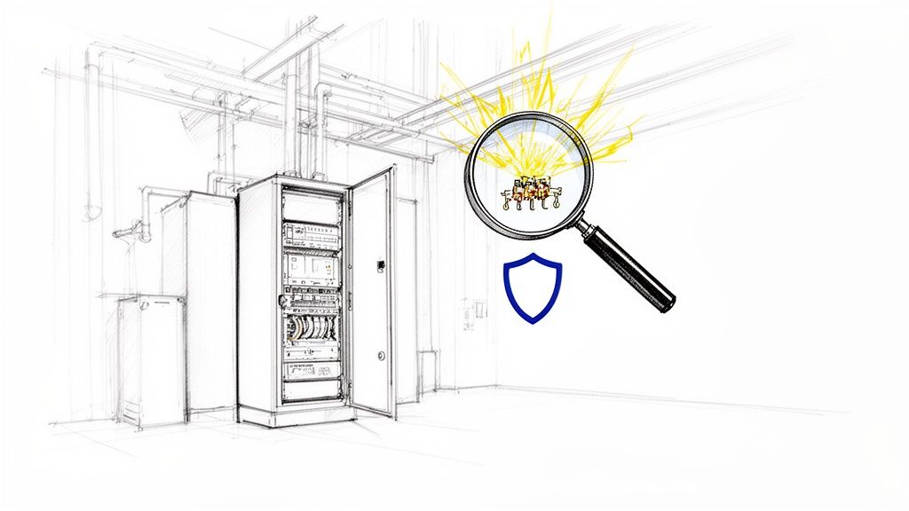
An arc flash hazard analysis is a deep-dive engineering study that figures out the sheer thermal energy that could be unleashed during an electrical fault. Think of it as a specialized forecast for your facility's electrical system, predicting the intensity of a potential explosion so you can protect your people from horrific harm.
Why an Arc Flash Analysis Is a Non-Negotiable Safety Pillar
Picture a lightning bolt trapped inside a metal cabinet. That’s the kind of raw, explosive power an arc flash can unleash. It’s a violent blast of energy that creates superheated plasma, blinding light, and a concussive pressure wave strong enough to throw a person across the room.
An arc flash hazard analysis goes way beyond just acknowledging this danger. It’s a meticulous investigation of your entire electrical system, calculating the precise level of hazard at every single point where your team might interact with energized equipment.
This isn't just about checking a box for compliance. It's about preventing life-altering injuries and fatalities. The numbers are grim: globally, there are an estimated 30,000 arc flash incidents every year. These events result in thousands of severe burn injuries and hundreds of deaths annually. You can get more insights on arc flash accident statistics from sources like AllumiaX. A proper analysis is the first and most critical step to keep your facility from becoming another statistic.
Understanding the Core Objectives
The whole point of the study is to arm you with actionable data that keeps your team safe. It's a journey into the DNA of your electrical distribution network, starting from where the utility feeds your plant all the way down to individual control panels. By modeling how the system will react under fault conditions, the analysis answers the tough questions that are the bedrock of any real electrical safety program.
A comprehensive arc flash study nails down several key goals:
Identifies Hazards: It pinpoints the exact locations—like switchgear, motor control centers (MCCs), and panelboards—where arc flash and shock dangers are lurking.
Quantifies Risk: The analysis calculates the specific incident energy (measured in cal/cm²) that a worker could be hit with. This number is what directly determines the level of personal protective equipment (PPE) they need to wear.
Defines Safety Boundaries: It establishes clear, non-negotiable approach boundaries. This includes the Arc Flash Boundary, which is the distance from the equipment where an unprotected worker would suffer a second-degree burn.
Ensures Compliance: The process is essential for meeting the critical safety standards mandated by OSHA and detailed in industry guides like NFPA 70E.
An arc flash analysis transforms an invisible, unpredictable electrical threat into a known, manageable risk. It replaces guesswork with data, empowering your team to work safely and confidently around energized equipment.
Ultimately, skipping this process isn't just a compliance miss—it’s a direct threat to your people, your equipment, and your ability to stay in business. The analysis lays the foundation for everything else, from accurate equipment labeling and PPE selection to effective worker training. It’s how you build a workplace where safety isn't left to chance.
Decoding the Standards: NFPA 70E and IEEE 1584
Trying to get a handle on electrical safety standards can feel like learning a new language. When you're dealing with an arc flash hazard analysis, two documents are the absolute bedrock of the entire process: NFPA 70E and IEEE 1584. They work in tandem, but they have very different jobs.
Here’s the best way to think about it: NFPA 70E is the “Rulebook for Safe Electrical Work,” while IEEE 1584 is the “Engineering Manual” that gives us the math. One tells you that you have to figure out the danger and how to act around it; the other tells you exactly how to calculate its intensity.
Getting how these two standards play off each other is non-negotiable for anyone in charge of electrical safety. They aren't interchangeable—they're deeply connected, creating a complete system to keep your team out of harm's way.
NFPA 70E: The Rulebook for Safe Practices
The National Fire Protection Association's NFPA 70E, officially the Standard for Electrical Safety in the Workplace®, is your go-to guide for safe work practices. It lays out what employers and employees must do to protect against electrical hazards, focusing on real-world application and human behavior.
At its core, NFPA 70E answers one critical question: "What do we need to do to keep our people safe?" It sets the stage for creating and maintaining an electrically safe work environment.
Here's what NFPA 70E demands:
Establish an Electrically Safe Work Condition: This is the top priority. The standard makes it crystal clear that de-energizing equipment is always the safest route, and it outlines the exact steps for lockout/tagout.
Perform a Risk Assessment: It mandates that employers identify electrical hazards, figure out the likelihood and severity of an injury, and put protective measures in place. This is the origin point for needing an arc flash study.
Select Personal Protective Equipment (PPE): The standard provides the framework for choosing the right arc-rated clothing and other PPE based on the hazards you’ve identified.
Label Equipment: NFPA 70E requires that electrical gear likely to be worked on while energized must have a label detailing specific arc flash hazard information.
NFPA 70E is the bridge between regulations and what your team actually does on the floor. It doesn't get into the weeds with complex formulas, but it sets the firm expectation that a detailed analysis must be done to understand the risks workers are up against.
This standard is the entire reason facilities conduct an arc flash hazard analysis. It’s the "why" behind the whole effort, all driven by the simple goal of making sure every single worker goes home safe.
IEEE 1584: The Engineering Calculation Engine
While NFPA 70E tells you to assess the hazard, the Institute of Electrical and Electronics Engineers' IEEE 1584, the Guide for Performing Arc-Flash Hazard Calculations, provides the accepted engineering muscle to get it done. This is the technical engine that powers the whole analysis.
If NFPA 70E is the rulebook, think of IEEE 1584 as the high-powered calculator. It’s packed with the detailed, empirically-derived equations needed to accurately predict the incident energy from a potential arc flash. This is a highly technical document built for the engineers running the numbers.
The main job of IEEE 1584 is to give us a standardized, repeatable way to calculate:
Arcing Short-Circuit Current: This is the amount of current that actually flows through the plasma arc—it’s different from the bolted fault current you might be used to seeing.
Incident Energy: This is the big one. It’s the amount of thermal energy (measured in cal/cm²) that would hit a worker at a specific distance from the arc. It's the key number for choosing the right PPE.
Arc Flash Boundary: This is the "stay-back" distance from a potential arc where the incident energy drops to 1.2 cal/cm²—the point where a second-degree burn can happen.
The formulas in IEEE 1584 are incredibly granular, taking things like system voltage, electrode configuration, equipment type, and conductor spacing into account. That level of precision is what makes the final results of an arc flash hazard analysis something you can truly count on.
The Arc Flash Hazard Analysis Process From Start to Finish
So, what exactly is an arc flash hazard analysis? Think of it as creating a digital twin of your entire electrical system so you can safely simulate the absolute worst-case scenarios without putting anyone in harm's way. It’s an engineering study that turns an abstract electrical threat into a known, measurable risk you can plan for.
The whole process lives and dies by one simple rule: accuracy at every step. Even a tiny mistake during the initial data gathering can snowball into a massive miscalculation later on, leading to the wrong PPE recommendations and a dangerously false sense of security. It's a methodical process where each stage builds on the last, creating a reliable blueprint for electrical safety.
And this isn't just a niche concern anymore. The global market for arc flash risk assessments is expected to jump from USD 0.6 billion in 2025 to USD 0.9 billion by 2035. That's not just a number—it shows a major global shift toward proactive safety, pushed by tougher regulations and the real-world need to protect people on the ground. You can read more about these arc flash assessment market trends on futuremarketinsights.com.
Step 1: Data Collection and Site Survey
This is where the real detective work begins, and it's the foundation for everything that follows. We start by collecting all the existing paperwork we can find—electrical one-line diagrams, equipment specs, and fault current data from the utility company. This gives us a starting map of your facility's electrical distribution.
But here’s the thing: documents are almost always out of date. That's why the next step, a physical site survey, is non-negotiable. A qualified engineer has to physically walk down the entire system to verify every single piece of information. They're meticulously checking everything from transformer nameplates and conductor sizes to the exact settings on every circuit breaker and fuse.
For an analysis to be worth its salt, you absolutely have to gather the right information from the get-go. Here’s a look at the essential data points we're after during that site survey.
Key Data Points for an Arc Flash Analysis
Data Category
Specific Information Required
Why It's Critical
Utility Source
Available short-circuit current from the electric utility.
This is the starting point for all fault current calculations. Without it, the entire study is based on a guess.
Transformers
kVA ratings, primary/secondary voltage, impedance (%Z).
Transformer impedance is a major factor in limiting fault current; incorrect values will skew all results.
Conductors
Length, size (AWG/kcmil), and material (copper/aluminum) of all cables and busways.
The length and size of a conductor determine its resistance, which affects the amount of fault current that can reach downstream equipment.
Protective Devices
Manufacturer, model, and specific trip settings for all circuit breakers, relays, and fuses.
These settings determine how quickly a device will operate to clear a fault, which is a direct input for calculating the duration of an arc flash.
This hands-on verification isn't just about double-checking—it's about ensuring the digital model we build in the next phase is a perfect mirror of what’s actually installed in your facility.
Step 2: System Modeling and Analysis
Once we have all that verified data, we head back to the office and use specialized software to build a detailed computer model of your electrical system. This digital replica is where the magic happens, allowing us to simulate fault conditions without anyone or anything getting hurt.
With the model built, we run a series of interconnected engineering studies:
Short-Circuit Study: First, we calculate the maximum potential fault current that could flow at every single point in your system. This number is the bedrock for all the other calculations.
Protective Device Coordination Study: Next, we analyze how your breakers and fuses work together. The goal is to make sure the device closest to the fault trips first, isolating the problem without knocking out a whole section of your plant.
Arc Flash Calculation: Finally, we take the results from the first two studies and plug them into the complex formulas from the IEEE 1584 standard. The software then crunches the numbers to determine the incident energy and arc flash boundary for each piece of gear.
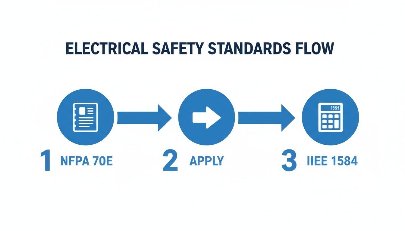
This flowchart really shows how the overarching safety standards connect to the nitty-gritty technical calculations.
It all flows from NFPA 70E's mandate for safety down to IEEE 1584's "how-to" guide for the calculations. This is what makes an analysis both compliant and truly effective.
Step 3: Reporting and Label Generation
The final step is all about translating those complex engineering calculations into clear, practical information your team can use every day. The main deliverable is a comprehensive report that breaks down the findings, assumptions, and our recommendations for reducing risk.
A key output of any arc flash hazard analysis is the equipment label. This isn't just a sticker; it's a critical communication tool that instantly tells a qualified worker the specific hazards they face and the PPE required to work safely.
We generate these labels and install them on every piece of equipment we analyzed—switchgear, panelboards, motor control centers, you name it. They provide the at-a-glance data needed for safe work practices, like the incident energy level and the required working distance.
This whole process closes the loop, turning theoretical data from a computer model into a practical, life-saving tool right there on the plant floor. To see how these principles apply to even larger power systems, you can dig into our guide on electrical substation design.
Putting Your Arc Flash Study Results into Action
An arc flash hazard analysis is just a pile of data until you actually do something with it. The final report and its complex calculations are the blueprint for a safer facility, but the real value comes from using that information to protect your team on the plant floor, day in and day out. This is where the engineering study meets the real world.
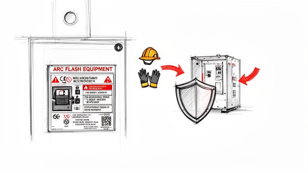
The most visible result of the analysis is the new arc flash label stuck to your electrical equipment. This isn't just another warning sticker; it's a critical safety dashboard. It gives qualified workers the vital, on-the-spot information they need to work safely. Getting a handle on what these labels mean is the first step in turning study results into real protection.
How to Read an Arc Flash Label
Think of an arc flash label as the "nutritional facts" for electrical hazard exposure. It instantly tells a worker what they're up against and what they need to wear to go home in one piece. While the exact layout might look a little different from one place to the next, every NFPA 70E-compliant label has to include a few key pieces of information.
Here’s what you need to look for:
Incident Energy: This is the big one, the headline number. It’s measured in calories per square centimeter (cal/cm²) and tells you exactly how much thermal energy could hit a worker at a specific distance. If a label shows 8.2 cal/cm², the worker must be wearing PPE with a rating that meets or beats that number. No exceptions.
Arc Flash Boundary: This is your "stay-back" line. It marks the perimeter where an unprotected person could get a second-degree burn (where incident energy hits 1.2 cal/cm²). Anyone who isn't a qualified worker has no business crossing this boundary when the gear is being serviced.
Required PPE: The label cuts through the confusion by either listing the incident energy or spelling out the required Arc-Rated (AR) PPE Category. This takes all the guesswork out of the equation.
Shock Hazard Information: Don't forget about shock. The label also details the voltage level and the "approach boundaries" (Limited and Restricted) to keep workers safe from electrocution.
The arc flash label is the most direct link between the engineering analysis and the person doing the work. It turns complex calculations into simple, life-saving instructions.
Mitigation Beyond Just Wearing PPE
Look, PPE is the absolute last line of defense. It's essential, but the real goal is to engineer the hazard away completely. A good arc flash hazard analysis doesn't just point out the dangers; it gives you the hard data you need to implement strategies that actually fix the problem at its source. This is where the hierarchy of controls comes in, pushing us to find engineering and administrative fixes instead of just relying on gear.
The cost of getting this wrong is staggering, both in dollars and in human lives. The arc flash protection market is on track to hit USD 3.6 billion by 2035, a number fueled by the awful consequences of these events. With more than 2,000 workers hospitalized every year from arc blasts and a single incident often costing over $1 million, being proactive isn't just about safety—it's a smart business decision. You can dig into the growth of the arc flash protection market on factmr.com.
Before we dive into specific engineering controls, let's look at the big picture. The "Hierarchy of Controls" is a framework used in safety management that ranks risk control methods from most to least effective.
Arc Flash Mitigation Hierarchy of Controls
The idea is simple: it's always better to remove the hazard entirely than to just put up a shield against it. This table breaks down the different levels of control.
Control Level
Example Strategy
Impact on Risk
Elimination
De-energize the equipment before work begins.
Completely removes the arc flash and shock hazard.
Substitution
Replace older, high-risk equipment with modern arc-resistant switchgear.
Replaces a high hazard with a significantly lower one.
Engineering
Adjust protective device settings for faster clearing times.
Reduces the severity of the hazard if an event occurs.
Awareness
Install clear arc flash warning labels and conduct regular training.
Informs workers of the danger but doesn't reduce the hazard itself.
Administrative
Implement a robust electrical safety program and safe work permits.
Changes how people work around the hazard.
PPE
Require workers to wear appropriate arc-rated clothing and face shields.
Protects the worker but does nothing to reduce the actual hazard.
As you can see, relying solely on PPE is the least effective—though still necessary—approach. The real wins come from moving up the hierarchy.
Engineering Controls to Reduce Hazards
Engineering controls are the heavy hitters because they physically change the system to make it safer. They're designed to either dramatically lower the incident energy or make an arc flash far less likely to happen in the first place.
Here are a few powerful engineering strategies we often recommend:
Adjusting Protective Device Settings: Sometimes, the simplest fix is the best. Tweaking the trip settings on an upstream circuit breaker can slash the arc duration. A faster trip means the arc has less time to build up and release its destructive energy, which directly lowers the incident energy. This is often done as part of a coordination study. For a refresher on the basics, check out our article on proper circuit breaker sizing.
Installing Arc-Resistant Switchgear: This is the gold standard. This specialized gear is built to contain an arc flash and blast the energy up and away from a worker standing in front of it. It’s a top-tier solution for new builds or major upgrades in your most critical areas.
Using Remote Racking or Switching: These systems are a game-changer. They let operators rack breakers in or out from a safe distance, well outside the arc flash boundary. You're physically removing the person from the line of fire, which is a massive leap forward in safety.
Implementing Arc-Limiting Fuses: Don't sleep on modern fuses. Today's current-limiting fuses can snuff out a fault in less than half a cycle, cutting the energy off at the knees before it can grow into a monster. This is often a surprisingly cost-effective way to retrofit existing gear and knock down the incident energy on everything downstream.
Documentation, Training, and Maintaining Compliance
Getting your arc flash hazard analysis done is a huge step, but it’s really the starting line, not the finish. The study gives you a pile of critical documents, and the real work begins now: turning that data into a living, breathing part of your facility's safety culture.
If that report just sits on a shelf collecting dust, you’ve missed the point entirely. This final phase is all about taking complex engineering data and making it practical and sustainable for your team on the ground.
The main deliverables—the final report, your freshly updated one-line diagrams, and all those new equipment labels—are your new foundation. They're a detailed snapshot of your system's hazards, a roadmap for safe work practices, and the guide for any future electrical work.
But documents don't keep people safe. People do. This is where training becomes the single most important part of your investment.
Training Your Qualified Persons
At the end of the day, it all comes down to the human element. NFPA 70E is crystal clear on this: only 'qualified persons' can work on or near energized equipment. That’s not just a title; it means they have the specific skills and safety training to recognize the dangers and, more importantly, how to avoid them.
Your training needs to hit these key points hard:
Hazard Recognition: Teaching your crew to instantly spot the difference between shock and arc flash hazards.
Label Interpretation: Making sure every single worker can read an arc flash label, understand what "incident energy" and "arc flash boundary" mean, and grab the right PPE without hesitation.
Safe Work Procedures: Hammering home the right way to establish an electrically safe work condition, especially proper lockout/tagout (LOTO) protocols.
PPE Use and Care: It’s not enough to have the gear. They need to know how to use it, inspect it, and take care of it so it can take care of them.
Great training is what makes the numbers and warnings from the arc flash hazard analysis actually mean something on the plant floor. To really get into the weeds on this, check out our complete guide on what constitutes effective arc flash safety training.
An arc flash study tells you what the hazards are. Solid training teaches your team how to manage those hazards safely, day in and day out.
Maintaining Compliance as a Living Process
Your electrical system isn't a museum piece; it changes. Equipment fails and gets replaced, a new line is added, or the utility makes a change upstream. That's why an arc flash study isn't a "one-and-done" deal.
NFPA 70E actually requires you to review the analysis at least every five years, or anytime you make a major change to the system. Think of it as a living document.
This ongoing cycle looks something like this:
Documenting Changes: Get religious about updating your one-line diagrams the moment a significant change is made. Don't wait.
Periodic Reviews: Put it on the calendar. Every five years, a formal review is needed to make sure the study still reflects reality.
Refresher Training: Skills get rusty and people forget. Regular safety training keeps your team sharp and current.
This isn't just about arc flash, either. Consistently meeting security compliance in your business is a fundamental part of running a safe and responsible facility. It’s an active, never-ending process that protects your people, limits your liability, and builds a culture where everyone goes home safe.
A Few Common Questions About Arc Flash Studies
Even after you get the basics down, a lot of plant managers and safety pros still have questions about what an arc flash hazard analysis looks like in the real world. The process is critical, no doubt, but it can feel a bit overwhelming. Let's walk through some of the most common questions to clear things up.
Getting these details right is the difference between a study that just checks a box and one that actually keeps your team safe. Think of this as the practical FAQ for putting your electrical safety plan into action on the plant floor.
How Often Do We Really Need to Do This?
This is probably the number one question I get, and for good reason. An arc flash study isn't a "one-and-done" deal. Your electrical system is a living, breathing thing, and your analysis has to keep up with the changes to be worth anything at all.
The official word from NFPA 70E is that a facility's arc flash hazard analysis needs a full review at least every five years. This check-up makes sure the calculations still match what's actually happening in your system.
But—and this is a big but—other things can trigger a review much sooner than that five-year mark:
Big System Changes: If you add a massive motor, swap out a transformer, or significantly re-route your power distribution, the available fault current is going to change. That means you need to update the analysis right away.
Utility Power Changes: It happens. The utility company upgrades their substation or lines feeding your plant, which can crank up the available fault current at your front door. If they send you a notice about it, it's time to revisit your study.
Protective Device Tweaks: Swapping a fuse for a different type or changing a circuit breaker's trip settings might seem small, but it can drastically alter how long an arc lasts. A longer arc means higher incident energy, so any change like this requires an update.
Your arc flash analysis is basically a detailed hazard map for your electrical system. If you build a new road or the landscape shifts, you have to update the map. Otherwise, you're sending people out with bad directions.
Can OSHA Actually Fine Us for Missing Arc Flash Labels?
People get tangled up on this one all the time. An OSHA inspector won't write a ticket that specifically says "Violation of NFPA 70E, Article 130.5(H)." But can they fine you for it? Absolutely. OSHA just uses their own rulebook to enforce the same safety principles.
When it comes to arc flash, OSHA leans on a few key regulations to cite employers:
The General Duty Clause: This is the big one. Section 5(a)(1) says employers must provide a workplace "free from recognized hazards." Arc flash is about as "recognized" as it gets, and NFPA 70E is the industry's consensus on how to handle it. A missing label is a giant red flag that you're not addressing a known killer.
PPE Hazard Assessment (29 CFR 1910.132(d)(1)): This rule requires you to assess the workplace for hazards that demand PPE. The arc flash label is the direct output of that assessment for electrical work. No label usually means no assessment was ever done, leaving your workers guessing.
So, while the citation might not name-drop NFPA 70E, a missing label tells an inspector that a fundamental safety process—the arc flash hazard analysis itself—is either missing or ignored. That's a direct path to a citation.
What's the Difference Between the PPE Category Method and a Full-Blown Incident Energy Analysis?
NFPA 70E actually gives you two ways to figure out the right arc flash PPE. Knowing the difference is key to picking the right approach for your facility.
The PPE Category Method is often called the "table method." It's exactly what it sounds like. A qualified worker uses tables inside the NFPA 70E book to find a task (like racking in a breaker) on a certain type of equipment. If—and only if—the system's parameters fall within the table's very strict limits, it tells you the required PPE Category (e.g., CAT 2).
The Incident Energy Analysis Method is the full engineering study we've been talking about. This is where an engineer models your entire electrical system in specialized software to calculate the precise incident energy (measured in cal/cm²) at every single piece of equipment.
Here's a quick breakdown:
Feature
PPE Category Method (Tables)
Incident Energy Analysis (Study)
Accuracy
General. It's based on worst-case scenarios and assumptions.
Precise. It's calculated for your specific system's conditions.
Worker Burden
High. The worker has to verify fault currents and clearing times on the spot.
Low. The worker just reads the label and puts on the right gear. No guesswork.
Flexibility
Rigid. You can't use it if your system falls outside the table's narrow limits.
Super flexible. Gives you exact data for every piece of equipment you analyze.
Initial Cost
Cheaper upfront, since you're not paying for a deep-dive engineering study.
Higher initial investment for the engineering time and software modeling.
While the table method can be a compliant option for very simple, well-documented systems, the incident energy analysis is hands-down the safer and more reliable approach. It takes the guesswork and complex decision-making away from the person standing in front of the live gear, giving them a clear, data-driven instruction right on the label.
A solid, up-to-date arc flash hazard analysis is the bedrock of any modern electrical safety program. From the initial system modeling to the final labels and training, getting it right protects your people, period. At E & I Sales, we build the engineered UL-listed control panels and provide the system integration that creates a safe, reliable foundation. See how our expertise can support your next project.
Ever seen a device that's both a light switch and a bodyguard for your industrial equipment? That's the simplest way to think about a fuse disconnector switch. It's a single, rugged component that marries the manual on-off control of a switch with the automatic overcurrent protection of a fuse, letting you safely kill power for maintenance while shielding your machinery from electrical damage.
The Two-in-One Job of a Fuse Disconnector Switch
In any plant or on any factory floor, keeping people safe and machines running are the two pillars of a successful operation. The fuse disconnector switch is a cornerstone for both, handling two critical jobs at once. It’s not just a switch, and it’s certainly more than a simple fuse holder—it's an integrated safety device that solves some of the biggest challenges in industrial control.
This dual-function design is exactly why it's so dominant in the market. In fact, fused models accounted for a staggering 67.79% revenue share in 2023, within a global disconnect switch market valued at USD 15.02 billion. Why the preference? Because it’s a proven way to prevent catastrophic failures in industries where every minute of downtime costs a fortune. You can see more market data on disconnect switches over at Grand View Research.
To help clarify how it pulls off this double duty, let's break down its two primary functions.
Function
Mechanism
Primary Goal
Key Benefit
Circuit Protection
Fuse element melts during overcurrent or short circuit, breaking the circuit.
Protect downstream equipment from electrical damage.
Prevents costly equipment failure and extends asset life.
Manual Isolation
User operates a handle to physically separate electrical contacts (create an air gap).
Ensure a zero-energy state for safe maintenance and servicing.
Enables compliance with Lockout/Tagout (LOTO) procedures.
In essence, the fuse provides the automatic protection, while the switch provides the manual control needed for human safety.
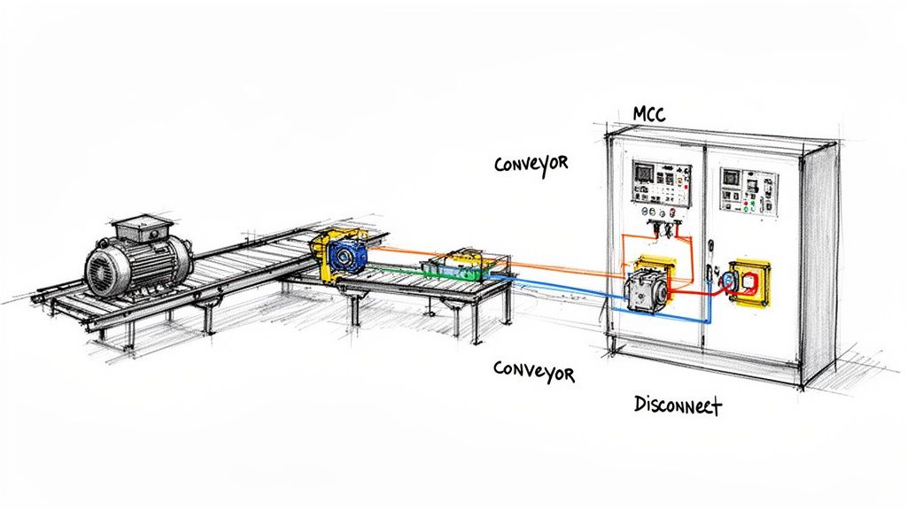
The Gatekeeper for Electrical Safety
First and foremost, the device is your local point of isolation. Picture a maintenance tech needing to work on a critical conveyor motor. Without a clear and verifiable way to de-energize that motor right where the work is happening, the job becomes incredibly dangerous. The disconnector’s handle provides that positive break, physically separating the contacts and creating a visible air gap in the circuit.
This is the bedrock of any Lockout/Tagout (LOTO) safety program. The handle is almost always lockable, ensuring the machine can't be accidentally powered back on while someone's hands are in it. It’s the definitive gatekeeper, guaranteeing a zero-energy state so your team can work safely. You can get a deeper dive into the basics of what a disconnect switch does in our detailed guide.
The Bodyguard for Valuable Equipment
At the same time, the device stands guard over your valuable assets. Housed inside are fuses, each one carefully sized for the specific circuit it’s protecting. If a short circuit or a dangerous overload condition occurs, the fuse element is designed to melt and break the circuit—all within milliseconds.
This rapid, sacrificial action stops destructive electrical energy dead in its tracks, long before it can fry expensive motors, VFDs, or PLCs. It’s the frontline defense that often makes the difference between swapping out a simple fuse and facing a multi-thousand-dollar repair bill.
By combining these two roles into one compact unit, the fuse disconnector switch gives you a cost-effective and highly reliable solution for both control and protection.
How a Fuse Disconnector Switch Actually Works
To really get a feel for what these devices do, you have to picture what’s happening inside the box, both when you throw the handle and when an electrical fault suddenly erupts. It’s less like a single component and more like a well-drilled team, with each part playing a role in control and protection.
At its core, the whole assembly is a clever marriage of a simple manual switch and a set of sacrificial fuses, all bundled into one neat package. You’ve got the handle on the outside, a switching mechanism on the inside, carriers to hold the fuses, and the all-important electrical contacts. When you pull that handle, you’re physically moving a linkage that forces the contacts apart, creating an air gap that cuts the power. Simple, reliable, and effective.
The Two Modes: Manual Control and Automatic Rescue
Every fuse disconnector switch lives a double life, operating in two very different but equally vital modes: manual isolation and automatic protection. Nailing down this dual personality is the key to understanding why they're so essential in a control panel.
Here's the breakdown of how each one works:
Manual Isolation: This is the hands-on part. An operator grabs the handle and moves it from ON to OFF. That simple physical action drives a cam or linkage inside, pulling the movable contacts away from the stationary ones. This creates a visible, verifiable air gap that completely de-energizes everything downstream, making it safe for a technician to get to work.
Automatic Overcurrent Protection: This is the "hero" mode. When a short circuit or a massive overload hits, a huge wave of current surges through the fuse. The little filament inside is designed to vaporize in milliseconds under that load, instantly breaking the circuit. The fuse sacrifices itself to save expensive motors, drives, and other critical gear from getting fried.
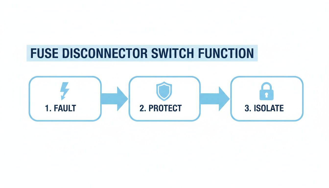
This flowchart really brings the process to life, showing how the switch responds to an electrical event.
You can see the straightforward logic: a fault occurs, the device protects the circuit, and then it provides a safe point of isolation.
A Growing Role in Modern Systems
The beautiful simplicity and rock-solid reliability of this mechanism are why we're seeing it in more places than ever. The global market for these panel-mounted switches was already valued at USD 2.8 billion in 2024. Projections show it climbing to USD 5.1 billion by 2034, growing at a steady 5.9% CAGR. What's driving this? A boom in construction and an unending need for industrial control panels that are, above all, safe. You can dig deeper into the market dynamics from this industry analysis.
The core principle is simple but powerful: the switch provides the deliberate, manual control needed for human safety, while the fuses offer the instantaneous, automatic protection required for equipment integrity.
In the end, it doesn't matter if it's an operator pulling the handle or a fault triggering the fuse—the result is the same. A safe, de-energized circuit. This dependable, two-pronged approach is what makes the fuse disconnector switch a non-negotiable part of any modern industrial electrical system. It's all about protecting both people and machinery.
How to Select the Right Fuse Disconnector Switch
Picking a fuse disconnector switch isn't like grabbing a generic part off the shelf. Get it wrong, and you're not just looking at a minor hiccup—you're risking damaged equipment, code violations, and serious hazards for anyone working on the panel. The right choice is the one that keeps your system protected and safe to service.
Making the right call means digging into the unique demands of your application. A switch destined for a tight motor control panel has a completely different set of requirements than one acting as the main disconnect for a massive piece of machinery. Your selection process needs to be a methodical, step-by-step evaluation of the electrical environment and what you're trying to protect.
Key Ratings You Cannot Ignore
Think of electrical ratings as the switch's DNA. If they don't match your system, it’s a recipe for disaster. Three ratings, in particular, are absolutely critical.
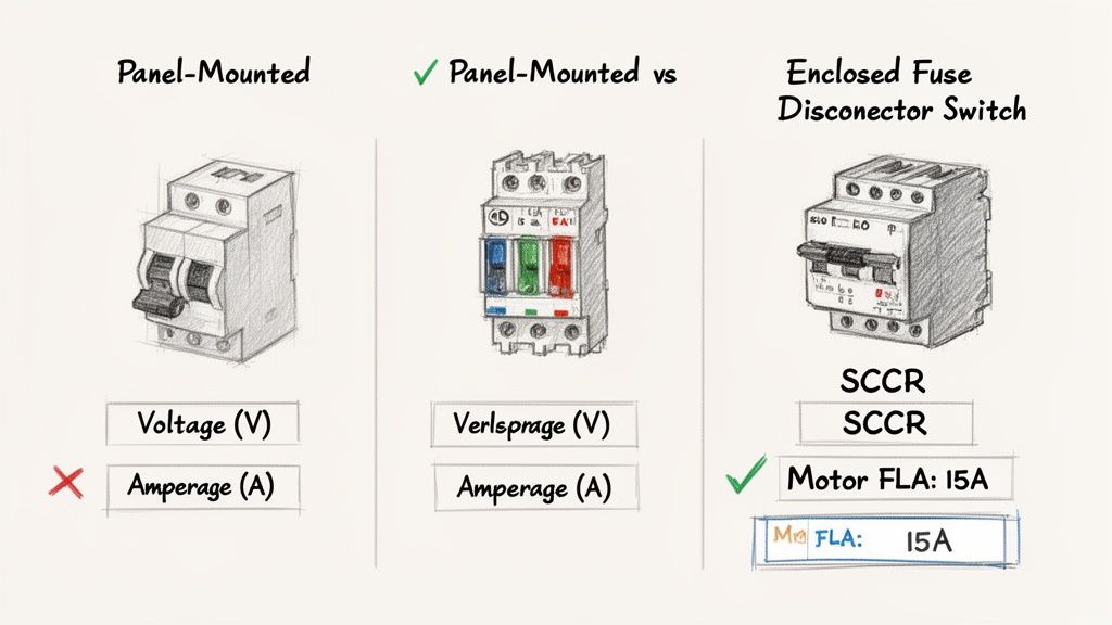
Voltage Rating (AC/DC): This is non-negotiable. The switch's voltage rating must be equal to or, even better, greater than your system voltage. Using an underrated switch is asking for insulation failure and dangerous arcing.
Continuous Current (Amperage): The switch has to handle the normal, everyday operating current of your circuit without breaking a sweat—or overheating. For motors, this is sized based on the Full Load Amps (FLA), usually with a safety factor baked in per code.
Short Circuit Current Rating (SCCR): This is arguably the most important safety rating of them all. The SCCR tells you the absolute maximum fault current the switch can safely interrupt without catastrophic failure. It must be higher than the available fault current where it’s installed.
The SCCR isn't a suggestion; it's a hard-and-fast safety metric. An improperly rated fuse disconnector can literally explode if it sees a fault current beyond its capacity, creating a life-threatening arc flash and destroying equipment.
The relentless push for safer industrial environments has made these devices essential. In fact, the global market for In-Line Fuse Switch Disconnectors hit a staggering US$4,612 million in 2024, a number driven by strict safety standards that demand reliable overcurrent protection and isolation. This focus on safety is paying off, helping to reduce downtime by up to 30% in critical operations by enabling faster, safer repairs. You can dig deeper into these trends over at Valuates Reports.
Sizing for a Motor Control Application
Let's walk through a real-world scenario that every panel builder and plant engineer has faced: sizing a disconnect for a 10 HP, 480V three-phase motor.
Find the Motor FLA: First, check the motor nameplate. A standard 10 HP motor at 480V will have a Full Load Amperage (FLA) right around 14 amps.
Size the Switch Amperage: The NEC tells us the disconnect needs to be rated for at least 115% of the motor's FLA. So, that’s 14A x 1.15 = 16.1A. You can't buy a 16.1A switch, so you step up to the next standard size, which is a 30A model.
Choose the Fuse Class and Rating: Here's where the nuance comes in. To handle the motor's inrush current on startup without blowing, you need a time-delay fuse. A Class J or RK5 fuse is perfect for this. The fuse amperage is sized higher than the FLA—often up to 175% or more, depending on the motor's code and design.
Verify the SCCR: Last but certainly not least, you have to check the available fault current in the panel. Let's say it's 18,000A. You'll need a switch and fuse combination with an SCCR of at least 25,000A (the next common rating up) to be safe.
Fuse Class Comparison for Motor Circuits
Choosing the right fuse class is just as important as sizing the switch. The fuse determines how the device responds to overloads and short circuits. For motors, you need something that can handle the initial startup surge but act instantly on a dead short.
Fuse Class
Key Characteristic
Typical SCCR
Best For
Class J
Fast-acting, current-limiting, compact size. Excellent for space-sensitive applications.
200,000A
High-performance motor protection where SCCR and physical space are critical.
Class RK5
Time-delay, current-limiting, dual-element design. Handles motor inrush well.
200,000A
General-purpose motor circuits. A great balance of performance and cost.
Class CC
Time-delay, compact, "midget" fuse footprint.
200,000A
Smaller control circuits and fractional horsepower motors. Not for larger loads.
Class T
Very fast-acting, extremely current-limiting, very compact.
200,000A
Protecting sensitive solid-state components like VFDs; less common for standalone motor disconnects.
By walking through this logical process—evaluating the ratings, understanding the load, picking the right fuse, and verifying the safety specs—you can specify a fuse disconnector switch that delivers both bulletproof protection and uncompromising safety.
Best Practices for Installation and Wiring
Getting the installation and wiring right on a fuse disconnector switch is about more than just making the lights come on. It’s about building a safe, reliable, and compliant system. A sloppy install is a ticking time bomb—it can lead to overheating, equipment failure, and serious hazards, especially inside a UL 508A control panel where every component has to pull its weight.
Think of it this way: the care you take here is the foundation of your entire electrical system. Do it right, and you've built something that will stand the test of time.
Mounting and Mechanical Setup
First things first, you have to physically secure the switch. The right method really depends on your panel's layout and the specific model you're working with.
DIN Rail Mounting: For smaller switches inside a control panel, this is the way to go. It's fast, usually tool-free, and makes it a breeze to move things around during assembly.
Panel (or Door) Mounting: Bigger, beefier switches are typically mounted straight onto the back panel or the enclosure door. This gives them a solid base and makes it easy to add a through-the-door operator handle.
That through-the-door handle is a non-negotiable for operator safety. It lets someone kill the power before they even think about opening the panel door, which is a massive step in preventing arc flash incidents. Make sure this handle is lockable to meet Lockout/Tagout (LOTO) standards.
Wire Termination and Connections
How you land your wires is just as critical as where you mount the switch. You’d be surprised how many electrical failures and fires come down to nothing more than a bad connection. Always double-check you're connecting incoming power to the line side and outgoing power to the load side. Getting that backwards can create a seriously dangerous situation.
When you're doing any of this work, having a solid permit to work system in place is essential. It's a structured way to manage hazardous jobs and ensure everyone stays safe by verifying that equipment is properly de-energized.
Pro Tip: Don't just guess on the tightness of your connections. Use a calibrated torque wrench. Manufacturers provide specific torque values for a reason. Over-tightening can strip or damage the terminal, while under-tightening creates a high-resistance spot that will do nothing but generate heat.
Finally, give the switch some breathing room. Both the NEC and UL standards require specific clearances around components. This isn't just for show—it prevents arcing and allows heat to dissipate properly. Jamming components together is a code violation and makes any future maintenance a nightmare.
Follow these practices, and you'll end up with a clean, safe, and inspection-ready panel. If you’re just starting your panel build, our guide to industrial control panel design has a lot more tips to get you going.
Navigating Safety Standards and Code Compliance
A fuse disconnector switch isn't just another part in a control panel; it's a critical link in the safety chain. Getting bogged down in the alphabet soup of safety standards can be frustrating, but understanding the why behind them is what really matters. These rules, created by organizations like UL, NFPA, and OSHA, exist for one reason: to prevent catastrophic electrical failures and keep people safe.
Think of it this way: compliance isn't about checking a box to pass an inspection. It’s about building systems that are fundamentally reliable. When a maintenance tech needs to service a piece of machinery, they have to be absolutely certain that throwing the disconnect handle creates a true zero-energy state. Their life depends on it.
The Why Behind the Rules
The standards that apply to a fuse disconnector switch aren't just arbitrary rules. They’re the hard-won lessons from decades of real-world incidents, each designed to address a specific piece of the safety puzzle.
UL (Underwriters Laboratories): UL is all about the component's integrity. UL 98 specifically covers enclosed and dead-front switches, making sure they can handle the mechanical stress and electrical load of their job. Then you have UL 508A, the standard for industrial control panels, which dictates how that switch must be integrated into a larger, safe assembly.
NFPA (National Fire Protection Association): Most people know NFPA 70 as the National Electrical Code (NEC). This is the playbook for installation. It tells you exactly where disconnects need to be, how to size them, and what clearances are required to prevent fires and shock hazards.
OSHA (Occupational Safety and Health Administration): OSHA’s focus is squarely on the worker. Their regulations mandate Lockout/Tagout (LOTO) procedures, which are impossible without a lockable disconnect handle. This ensures a machine can't be accidentally turned on while someone is working on it.
At the end of the day, these standards work together to create a predictable, safe environment. A UL-listed switch, installed according to the NEC, and used as part of an OSHA-compliant LOTO program, forms an unbreakable chain of protection for both people and equipment.
SCCR and the Mandate for Safety
One of the most important—and often misunderstood—safety ratings on an industrial panel is its Short Circuit Current Rating (SCCR). This number tells you the maximum fault current the entire panel can handle without exploding or catching fire. The fuse disconnector switch is your first line of defense and is absolutely essential for achieving a high panel SCCR.
The fuses inside the switch have an incredibly high interrupting capacity, often 200,000A. This allows them to instantly protect all the downstream components—like VFDs or PLCs—that have much lower individual SCCR ratings. This makes the fused disconnect a foundational building block for any UL 508A compliant panel that is truly safe by design.
Keeping Your Switch Healthy: Maintenance and Troubleshooting
Even the toughest fuse disconnector switch is not a "set it and forget it" device. To keep them reliable and safe for the long haul, a little proactive care goes a long way. For any plant engineer or maintenance pro, getting ahead of problems is always better than reacting to a failure that causes unexpected downtime or, worse, a safety incident.
Think of it like this: regular maintenance is the key to catching small issues before they snowball into catastrophic failures. A few simple visual and mechanical checks can tell you everything you need to know about the health of your switch.
The Go-To Preventive Maintenance Checklist
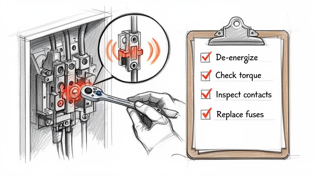
A simple, repeatable inspection is your best line of defense. Over months and years, machine vibration can work connections loose, and environmental factors like dust and humidity can take their toll. Building these steps into your routine PM schedule is non-negotiable.
Torque It Down: Connections are notorious for loosening up. Use a calibrated torque wrench to make sure every line and load terminal screw is tightened to the manufacturer’s spec. A loose connection is just a hot spot waiting to happen.
Work the Handle: With the power off, of course, cycle the handle a few times. It should feel smooth and solid, not stiff or sloppy. Any binding or excessive force is a red flag.
Look for Hot Spots: Your eyes are one of your best tools. Scan for any signs of discoloration or charring on the wires, terminals, or the switch body itself. That’s a dead giveaway of overheating from a bad connection or an overload.
Check the Fuses: Make sure the right fuses are in there. Verify they are the correct size, class, and amp rating for the circuit. Also, check that they're sitting snug and secure in the carriers.
Think of this as a quick physical for a critical piece of your safety system. Spending a few minutes on these checks can dramatically extend the life of the switch and keep your entire system safer.
The Right Way to Replace a Blown Fuse
Sooner or later, a fuse is going to do its job and blow to protect your equipment. When it does, replacing it has to be done by the book, with an absolute focus on safety. There are no shortcuts here.
Kill the Power & Lock It Out: The first step is always to throw the switch handle to the OFF position. Immediately follow that by applying your facility's Lockout/Tagout (LOTO) procedure to the handle. This ensures no one can accidentally flip it back on while you're working.
Verify It's Dead: Trust, but verify. Use a properly rated multimeter to test for voltage on both the line and load sides of the switch. Always test your meter on a known live source before and after you test the switch to prove your meter is working.
Swap the Fuse: Only after you’ve confirmed a zero-energy state should you open the fuse door or pull out the carrier. Replace the blown fuse with an exact match—same class, same voltage, and same amperage.
Power Up Safely: Once the new fuse is in, remove your lock and tag, close the panel door, and only then should you move the handle back to the ON position.
A Few Common Questions From the Field
When you're out there designing panels or walking a plant floor, the same questions about fused disconnects tend to pop up. Let's clear up a few of the most common ones we hear from engineers and technicians.
Fused vs. Non-Fused Disconnects: What’s the Real Difference?
Think of a non-fused disconnect as a simple light switch for your equipment—its only job is to provide a clear, visible break in the power for service. It’s purely for isolation and offers zero defense if something goes wrong electrically.
A fuse disconnector switch, on the other hand, is the whole package. It does that same critical isolation job and integrates overcurrent protection with fuses. It’s a single, compact device that protects your circuit from both dangerous short circuits and damaging overloads.
Can I Use One as a Motor Starter?
Absolutely not. A fuse disconnector switch is built for safety and protection, not for the constant, day-in-day-out cycling of starting and stopping a motor. That kind of repetitive action will destroy it.
For actually running a motor, you need a dedicated motor starter, like a contactor and overload relay combo. They’re designed for that specific, high-endurance task.
It boils down to this: a motor starter is for operation, while a fused disconnect is for protection and isolation. Mixing up their roles is just asking for equipment failure and creating a genuinely unsafe situation.
How Do I Pick the Right SCCR?
This is a big one. The Short Circuit Current Rating (SCCR) you need is all about the "worst-case scenario." You have to figure out the maximum available fault current at the exact spot you're installing the disconnect.
Your fuse disconnector switch and the fuses you put in it must have a combined SCCR that is equal to or, even better, greater than that number. This guarantees it can handle a massive fault without exploding. Getting this calculation right is a non-negotiable part of designing a safe, compliant panel that meets UL 508A and NEC standards.
For robust, reliable UL-listed control solutions that incorporate the right fuse disconnector switch from the start, you can trust the experts at E & I Sales. Find out more at https://eandisales.com.
At its core, a disconnect switch is a straightforward, manually operated device designed for one critical purpose: to completely and visibly cut off a circuit from its power source. Think of it as an electrical safety switch. Its entire job is to create a physical "air gap," a clear, undeniable break in the circuit that guarantees electricity cannot flow past it. This makes it an absolute necessity for safe maintenance, repairs, or emergency shutdowns.
The Core Function of a Disconnect Switch
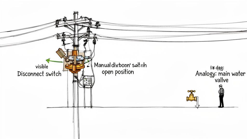
The best way to understand a disconnect switch is to think of it as the main water valve for your house.
When a plumber needs to fix a leaky pipe, they don't just turn off the faucet under the sink. They go straight to the main shutoff valve, closing it to ensure not a single drop of water can reach their work area. A disconnect switch provides that same level of absolute certainty for electricity.
This function isn't just about convenience; it's a cornerstone of electrical safety on the job. The ability to physically lock the switch in the "off" position is the foundation of the Occupational Safety and Health Administration's (OSHA) lockout/tagout (LOTO) procedures. This protocol is what stands between a technician and a machine that could accidentally be re-energized while they're working on it.
Why Visual Isolation Matters
You'll almost always find a disconnect switch installed "within sight" of the equipment it protects, and that’s by design. Unlike a circuit breaker that might be hidden away inside a panel down the hall, the disconnect switch gives a technician an immediate, visual confirmation that the circuit is dead.
That physical separation of contacts is the ultimate safeguard against electrical shock. There's no ambiguity.
A disconnect switch is a critical safety device in electrical systems, designed to physically isolate power circuits during maintenance, emergencies, or repairs, preventing accidents and ensuring worker safety in industrial settings.
Let's quickly summarize the key points in a table.
Disconnect Switch at a Glance
Key Aspect
Description
Primary Function
To safely and visibly isolate a circuit from its power source.
Mechanism
Creates a physical "air gap" in the circuit, preventing electrical flow.
Core Benefit
Ensures worker safety during maintenance and repairs.
Key Application
A critical component of Lockout/Tagout (LOTO) safety procedures.
Typical Installation
Placed "in-sight" of the equipment it controls for visual verification.
This at-a-glance view highlights just how fundamental these devices are in any robust electrical system.
Indispensable in Industrial Settings
For any company involved with motor control centers and UL-listed panels, disconnect switches are non-negotiable. They are essential for building reliable and code-compliant power distribution systems in manufacturing plants, automation projects, and beyond.
They act as the first line of defense, providing a secure way to isolate everything from a single motor to an entire production line. To get a better sense of what's driving the demand for these devices, you can explore detailed industry reports on the market.
A Look at the Main Types of Disconnect Switches
Not all disconnect switches are built the same; picking the right one is all about the job at hand. If you want to guarantee safety and keep your equipment running smoothly, you need to know the basic types. The biggest fork in the road is whether the switch provides its own overcurrent protection.
This single difference splits them into two major camps: fused and non-fused.
Fused vs. Non-Fused Switches
Think of a fused disconnect switch as a device wearing two hats. It’s both a manual "off" switch and a bodyguard for your circuit. Inside, it holds fuses that will blow and cut the power automatically if the current spikes to a dangerous level, saving an expensive motor or piece of machinery from getting fried.
A non-fused disconnect switch, on the other hand, has just one job: to isolate power. It's a purist. It offers zero overcurrent protection on its own, so it's only used in circuits where a circuit breaker or another device upstream is already handling that responsibility.
In a nutshell, fused switches give you isolation and overcurrent protection in one box, which is why they’re the go-to for motor circuits. Non-fused switches are strictly for cutting power, relying on a separate breaker to do the protecting.
It’s no surprise that fused switches dominate industrial settings. The low-voltage disconnect switch market, which is the backbone of motor control, was valued at $3.2 billion in 2023. The fused industrial slice of that pie is expected to hit $4.6 billion in 2024, which tells you just how critical that built-in protection is for machinery. You can dig into more of the numbers by reviewing these detailed industry findings.
Common Designs and Duty Ratings
Beyond just fused or non-fused, you’ll run into different designs built for specific loads and environments. They’re often separated by a "duty rating," which is just a fancy way of saying how tough they are.
Here are a few of the workhorses you’ll find out in the field:
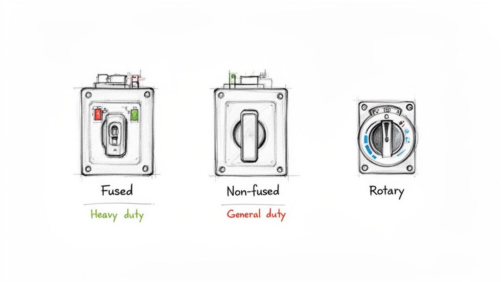
Heavy-Duty Safety Switches These are the tanks of the disconnect world. Built for the grind of industrial applications, they’re designed for frequent use and can safely handle the high fault currents you see with big motor circuits and heavy machinery.
General-Duty Safety Switches Just like the name says, these are for lighter commercial or even residential jobs where the switch won't be thrown every day. They're a more budget-friendly option for things like service entrances or light-duty branch circuits where you don't need an industrial-grade build.
Rotary Disconnect Switches These guys are compact, versatile, and often found mounted right on a control panel or machine. A simple turn of the handle opens or closes the contacts. They are perfect for providing a local shut-off right where you need it, especially when space is tight. Panel builders love them for their small footprint and modular design.
Choosing between them means looking at what the circuit needs—everything from the electrical load and environmental conditions to the specific safety codes you have to follow.
How Disconnects Differ From Breakers and Contactors
It’s easy to get electrical components mixed up, especially when they all seem to "switch" power in one way or another. One of the most common points of confusion is the difference between a disconnect switch, a circuit breaker, and a contactor.
While they all sit in a circuit and control the flow of electricity, their core jobs are fundamentally different. Trying to substitute one for another is a recipe for an unsafe, unreliable system.
An Everyday Analogy: Your Home's Plumbing
Let's think about it in terms of the water flowing into your house. It's a surprisingly good parallel.
A contactor is like your kitchen faucet. You turn it on and off constantly throughout the day for a specific task. It’s designed for frequent, routine operation.
A circuit breaker is the emergency flood-stop valve in your basement. It sits there, doing nothing, until a pipe bursts. When it detects that sudden, dangerous rush of water, it snaps shut automatically to prevent a catastrophe.
The disconnect switch is the main water shutoff valve out by the street. A utility worker has to come out, turn it with a special tool, and lock it in the "off" position to guarantee no water can enter the house during major repairs. It’s a deliberate, manual safety action.
Unpacking the Core Functional Differences
The real distinction boils down to manual vs. automatic and safety vs. operational control.
A disconnect switch is a purely manual device, built for one thing: absolute safety isolation. When you throw that handle, you are physically creating a visible air gap in the circuit. There’s no ambiguity. It’s a guarantee that the circuit is de-energized so someone can safely perform maintenance. Its purpose is entirely focused on protecting people.
A circuit breaker, on the other hand, is an automatic safety device. It’s always on watch, monitoring the circuit for overloads and short circuits. The moment it detects a dangerous fault condition, it "trips" on its own to cut the power and protect the equipment from burning up. While you can often operate a breaker manually, its primary job is automatic protection.
Contactors play a completely different role. They are electrically operated switches, designed to be turned on and off frequently by a remote signal. A small control voltage energizes a coil, which pulls the main contacts closed to power up a motor or heater. They're all about operational convenience, not providing a positive, lockable point of isolation for safety.
The key takeaway is simple: Disconnects are for manual safety isolation, breakers are for automatic equipment protection, and contactors are for operational remote control. Each plays a distinct and non-interchangeable role.
To make this crystal clear, let's put them head-to-head.
Disconnect Switch vs Circuit Breaker vs Contactor
This table breaks down the essential differences at a glance, highlighting why you need the right component for the right job.
Component
Primary Function
Operation
Typical Application
Disconnect Switch
Safety Isolation
Manual (handle-operated)
De-energizing equipment for Lockout/Tagout (LOTO)
Circuit Breaker
Overcurrent Protection
Automatic (trips on fault)
Protecting circuits from overloads and short circuits
Contactor
Operational Control
Remote (electrically controlled)
Frequently starting and stopping motors
Understanding these distinct roles is the cornerstone of designing safe and compliant electrical systems. While a device like an ABB circuit breaker is a critical protective device, it simply cannot provide the same guaranteed, visible, and lockable isolation that a true disconnect switch offers. Using the right tool for the job isn't just a best practice—it's essential for a safe and reliable installation.
Where You'll Find Disconnect Switches in the Real World
Let's move from the textbook definitions to the factory floor. Disconnect switches aren't just a good idea; they're the non-negotiable heroes of nearly every industrial setting, crucial for both safety and keeping operations running smoothly.
Picture a massive manufacturing plant with conveyor belts, pumps, and mixers all humming along, powered by hundreds of electric motors. What happens when one motor on a critical production line needs a new bearing? You can't just shut down the entire facility. That would be a logistical and financial nightmare.
This is exactly where the disconnect switch proves its worth.
By placing a disconnect right at the motor, a technician can walk up, throw the handle, and completely isolate that single piece of equipment. This local cutoff point guarantees the machine is de-energized, making it safe for repairs while the rest of the plant keeps on producing.
Critical Roles Across the Plant
Once you know what to look for, you'll start seeing disconnect switches everywhere in a factory. Their presence is the sign of a thoughtfully designed and safe electrical system.
Here are some of the most common spots you'll find them:
Motor Control Centers (MCCs): These are the command centers for a plant's motors. Each motor "bucket" or unit inside the MCC gets its own disconnect, letting you safely work on one motor circuit without affecting the others.
Main Machinery Power: Every major piece of equipment—from a CNC mill to a giant hydraulic press—needs a main disconnect. This is the master "off" switch for the whole machine, absolutely essential for setup, maintenance, or hitting the brakes in an emergency.
HVAC and Pumping Systems: Think about the powerful systems running large commercial chillers, air handlers, and water pumps. Electrical code often requires a disconnect to be installed "within sight" of this equipment so a technician can kill the power right before putting their hands on it.
UL-Listed Control Panels: For a custom control panel to earn a UL 508A listing, it has to provide a way to cut all incoming power. A flange-mounted disconnect handle right on the enclosure door is the industry standard for meeting this requirement safely and effectively.
The market data really drives this point home. The industrial sector accounted for a staggering 43.71% of all disconnect switch sales in 2023. Why? Because industries like manufacturing and power generation rely on them to prevent downtime, which can easily cost millions. You can dig into the numbers in this disconnect switch market trends report.
At the end of the day, in any industrial environment, the disconnect switch is the physical barrier between high-voltage power and a human being. Its simple, tough design provides the clear, visible, and lockable power isolation that stops catastrophic accidents and costly shutdowns before they can happen.
Navigating Key Codes and Safety Standards
In the world of industrial power, a disconnect switch isn't just a good idea—it's a hard requirement, baked into the safety codes that govern everything we do. These standards are the rulebook, transforming a simple piece of hardware into a non-negotiable device that protects both people and equipment.
It all starts with the National Electrical Code (NEC). If you're dealing with motors, you live in Article 430. One of its most critical mandates is the "within sight" rule, which demands that a disconnect must be visible and located no more than 50 feet from the equipment it serves. This isn't arbitrary; it's a practical safeguard that prevents a technician from working on a machine while someone unknowingly re-energizes the circuit from down the hall.
Connecting Hardware to Human Safety
While the NEC lays out the rules for the hardware, the National Fire Protection Association (NFPA) focuses on keeping people safe around it.
That's where NFPA 70E, the Standard for Electrical Safety in the Workplace, comes in. This is the playbook for safe work practices, and it’s the reason we have procedures like Lockout/Tagout (LOTO). A disconnect switch is the linchpin of any LOTO procedure, providing that essential, lockable point of isolation that NFPA 70E requires before a single tool is lifted.
Think of it this way: The NEC tells you how and where to install the disconnect. NFPA 70E tells you why and how to use it to make sure everyone goes home safe.
The Role of UL Certification
For anyone building control panels, Underwriters Laboratories (UL) standards are gospel. UL provides that critical third-party stamp of approval, verifying that components and entire assemblies meet rigorous safety and performance benchmarks.
Two standards are absolutely essential here:
UL 98 (Enclosed and Dead-Front Switches): This is the standard for the disconnect switch itself. It gets put through its paces to ensure it can reliably interrupt current and handle nasty fault conditions without failing.
UL 508A (Industrial Control Panels): This one applies to the whole finished product—the control panel. To earn that coveted UL 508A listing, the panel must have a certified main disconnecting means. That makes a UL 98-rated switch a foundational building block for any compliant panel.
Picking the right disconnect switch goes way beyond just matching the voltage and amperage on the label. Get this choice right, and you’re setting your system up for safety, reliability, and code compliance. Get it wrong—say, by undersizing the switch or picking the wrong enclosure—and you're looking at premature failure, serious safety hazards, and downtime that'll hit your bottom line hard.
You have to look at the whole picture. It's like choosing tires for a truck. You wouldn’t slap standard highway tires on a rig that's heading off-road, right? The same logic applies here. A general-duty switch just won't survive in a harsh industrial environment that demands a heavy-duty model.
Your Essential Selection Checklist
Before you even think about purchasing a disconnect switch, run through this checklist. Nailing these details from the get-go will save you from massive headaches later.
Horsepower (HP) Rating: This is non-negotiable if the switch is for a motor. Motors pull a massive amount of current when they first start up, and the switch absolutely must be rated to handle that specific motor load.
Enclosure Type: The environment is everything. Is it a corrosive or washdown area? You'll need a NEMA 4X enclosure. Just a dusty indoor spot? A NEMA 12 might do the job just fine.
Fault Current Rating: The Short Circuit Current Rating (SCCR) has to be high enough to handle the worst-case scenario. It must safely withstand the maximum potential fault current at that point in the system, preventing a catastrophic explosion during a short circuit.
Fused vs. Non-Fused: Do you need the switch itself to provide overcurrent protection (fused)? Or is there already a breaker or fuse upstream handling that job (non-fused)?
Choosing the right disconnect switch is a foundational step in building a safe electrical system. Overlooking a detail like the enclosure type or fault current rating doesn’t just risk the switch; it risks the equipment it protects and the personnel who operate it.
Best Practices for Long-Term Maintenance
Once it's installed, a disconnect switch isn't a "set it and forget it" device. It needs regular attention to stay reliable and safe throughout its service life. Neglecting maintenance is a common—and dangerous—mistake. The good news is that proactive care is pretty simple.
A solid maintenance plan is your best tool. If you're looking for a great starting point, check out the principles for maintaining motor control centers, as many of them apply directly to the disconnects inside.
Here are the key tasks to stay on top of:
Regular Inspections: Do a visual walk-through. Look for tell-tale signs of overheating, like discolored terminals or melted insulation. Check for any hint of corrosion or moisture getting inside the enclosure.
Connection Tightness: Things loosen up over time thanks to vibration and the constant heating and cooling of electrical cycles. Get a torque wrench out periodically and make sure all terminal lugs are tightened to the manufacturer's specs.
Mechanical Operation: During a planned outage, throw the handle. Operate the switch a few times to make sure the mechanism moves freely. You don't want to find out it's seized up from years of inactivity during an emergency.
Answering Your Top Questions About Disconnect Switches
Even after getting the basics down, a few common questions always seem to pop up on the plant floor. Let's clear up a couple of the most frequent points of confusion to sharpen your understanding and help you make safer, smarter decisions.
Can a Circuit Breaker Double as a Disconnect Switch?
Sometimes, yes—but it's a qualified "yes." The National Electrical Code (NEC) does allow a circuit breaker to serve as a disconnecting means, provided it has the right ratings for the job. Critically, it must have a way to be locked out in the "off" position to comply with LOTO procedures.
Even so, many seasoned electricians and safety professionals will tell you they prefer a dedicated, standalone disconnect switch. Why? Because a traditional disconnect gives you that unmistakable visual confirmation—a physical air gap between the contacts—that the circuit is truly dead. It’s an extra layer of assurance you just can't argue with.
What Does the NEC Mean by "Within Sight of the Motor"?
This is a huge one, and it's a safety rule you can't afford to get wrong. The NEC defines "in sight from" as being visible and located no more than 50 feet away from the equipment it controls, like a motor.
The reasoning here is brilliantly simple and life-saving. It's designed to stop one person from accidentally re-energizing a machine while another technician, hidden from view, is working on it. This rule ensures the person performing the maintenance has direct, immediate control over the power source.
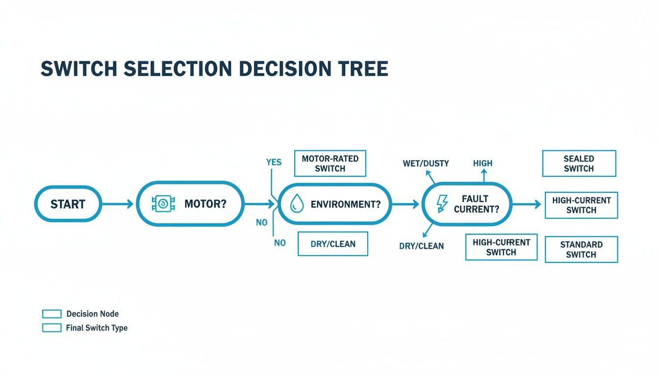
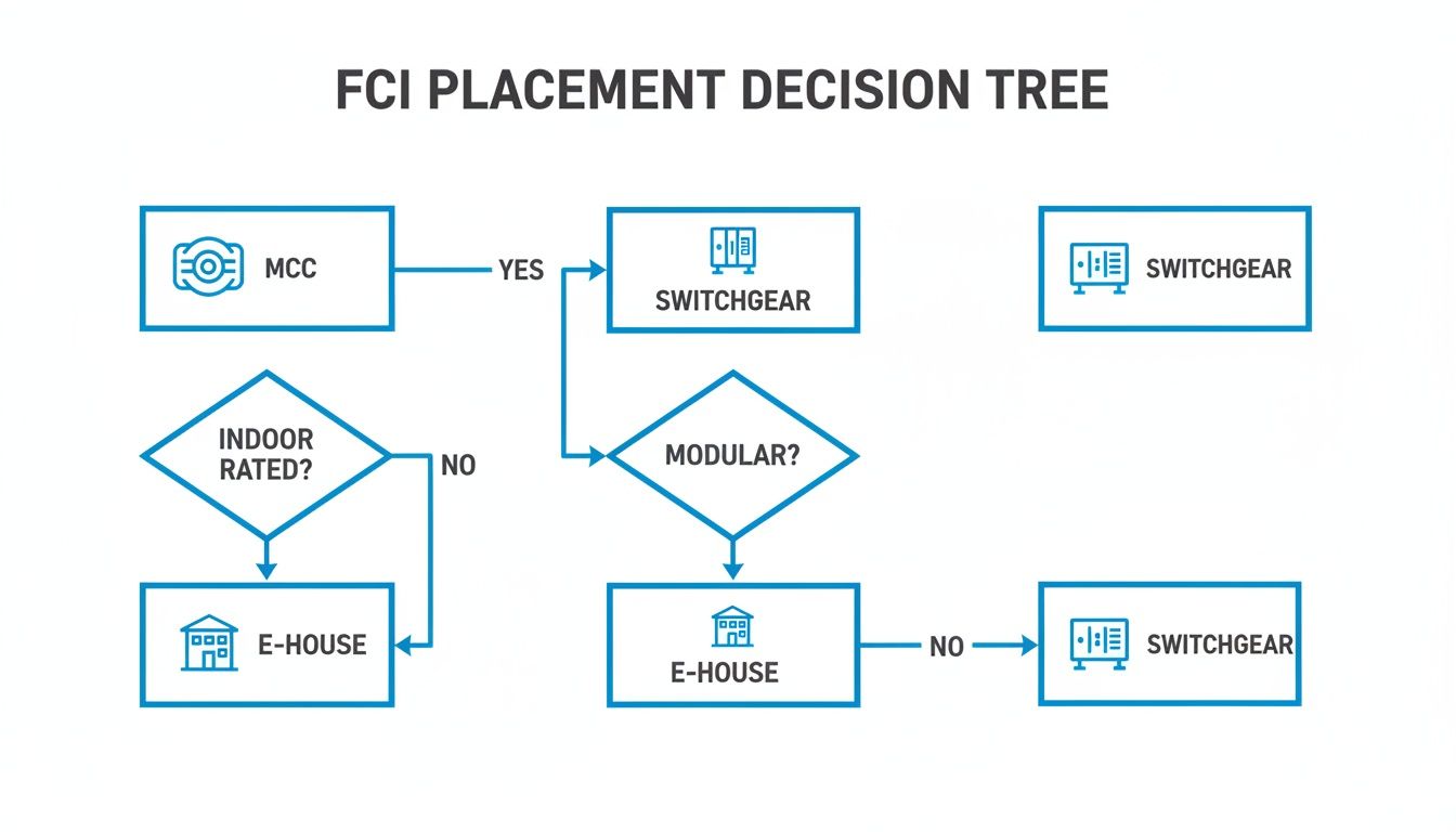
This decision tree gives you a great visual for the thought process behind choosing the right switch, walking through the key questions about the application, environment, and potential fault current.
As the guide shows, the single most important step is always matching the switch to its specific job.
Designing a safe, compliant, and rock-solid electrical system takes more than just buying components off a shelf—it demands a partner with deep experience in the field. At E & I Sales, we live and breathe this stuff, specializing in engineering UL-listed control panels and integrating motor controls built for the toughest industrial environments. Find out how our expertise can power your next project at https://eandisales.com.
Think of Fault Current Indicators, or FCIs, as the smoke detectors for your electrical system. They don't stop a fault from happening—like a short circuit or a ground fault—but they instantly tell you exactly where the problem is. This cuts troubleshooting downtime from hours to minutes, which is absolutely critical for safety and keeping operations online.
The Critical Role of Fault Location
In any complex industrial plant or data center, an electrical fault is never a small hiccup. It's a direct threat to your entire operation. When a vital circuit trips, the real challenge isn’t just fixing it; it’s finding it in the first place.
Without FCIs, maintenance crews are stuck in a painful process of elimination. They have to manually hunt through breakers and feeders, one by one, trying to track down the source. This "hunt-and-peck" method can drag on for hours, leaving production lines dead in the water and costing thousands in lost revenue with every tick of the clock.
The longer a fault remains hidden, the higher the risk of other equipment getting damaged. This is where FCIs prove their worth, turning a long, frustrating search into a quick, targeted fix.
From Hours to Minutes
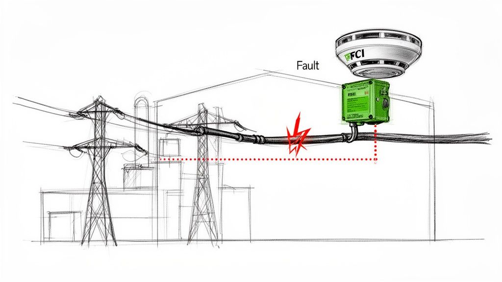
An FCI’s job is simple but powerful: provide a clear, impossible-to-miss signal right at the point of failure. This is usually a bright, flashing LED or a pop-up mechanical flag that immediately eliminates all the guesswork.
An FCI transforms a chaotic troubleshooting emergency into a controlled, directed response. Instead of your team asking, "Where do we even start looking?" they can see the faulted section instantly and get to work on isolation and repair.
This immediate visual cue empowers technicians to act fast. They can strategically bypass the affected circuit to get the rest of the facility back up and running while the repair is handled. This kind of tactical advantage is a cornerstone of modern electrical substation design and smart maintenance.
This isn't just a niche technology; it's a global standard. In recent years, over 1.2 million fault indicators were installed worldwide, a number that speaks volumes about their role in modernizing power grids. These devices can slash fault-finding time by up to 45%.
Core Functions of Fault Current Indicators
At their heart, FCIs do more than just point to a problem. They are a fundamental part of a system designed for safety, asset protection, and operational excellence. Here's a quick breakdown of what they do.
Function
Primary Benefit
Impact on Operations
Fault Detection
Instantly identifies abnormal current surges from short circuits or ground faults.
Reduces the need for manual circuit testing, saving valuable technician time.
Visual Indication
Provides a highly visible local alert (LED, flag) at the fault location.
Allows maintenance staff to quickly pinpoint the exact feeder or cable that has failed.
Rapid Isolation
Enables faster isolation of the faulted circuit segment from the main system.
Minimizes the scope of the outage, keeping unaffected parts of the facility online.
Downtime Reduction
Drastically cuts the time required to locate and address electrical faults.
Boosts Overall Equipment Effectiveness (OEE) and maintains production schedules.
Ultimately, integrating FCIs into your infrastructure is a proactive step toward a more resilient and efficient electrical system. They provide the clarity needed to keep small issues from turning into major operational disasters.
How Fault Current Indicators Actually Work
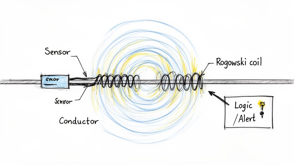
At its heart, a fault current indicator is a simple device built for a complex and critical job. Imagine it as a watchdog clamped onto a power cable, constantly monitoring the flow of electricity. Under normal conditions, this current hums along predictably.
But when a fault happens—like a dead short or a ground fault—the game changes in an instant. The current surges to many times its normal level, creating a massive, sudden spike. The FCI’s entire job is to see that specific event and raise an immediate, obvious alarm.
To pull this off, FCIs use some clever sensing technology that can pick up on these abrupt changes without ever making direct electrical contact with the live conductor. This non-invasive design is what makes them so safe and easy to install in tight, energized spaces.
Sensing the Surge
The real magic behind an FCI is its ability to measure the effects of electrical current from a safe distance. Two main technologies have become the go-to methods, each with its own way of spotting the tell-tale signs of a fault.
Magnetic Field Sensors: Every current-carrying wire generates a magnetic field. When a fault occurs, that massive spike in current creates an equally massive and instantaneous expansion of this magnetic field. These sensors are designed to react to that powerful change, tripping an alarm the moment the field strength blows past a preset threshold.
Rogowski Coils: A Rogowski coil is essentially a specialized, air-cored loop of wire that acts as a precision current transducer. Because it lacks a magnetic core, it can't get saturated by huge current spikes. This makes it incredibly good at measuring very fast-changing currents (high di/dt, or rate-of-rise) and, more importantly, distinguishing a real fault from a temporary inrush current, like when a big motor kicks on. If you want to dig deeper into what causes these events, we have a guide on what can cause a breaker to trip.
This diagram shows a Rogowski coil in action, measuring current and signaling a fault.
You can see the core parts at play: the coil wrapped around the conductor, the sensor that interprets its signal, and the logic that trips the alert. It’s an elegant solution for accurate fault detection without risky direct contact.
The Anatomy of an FCI
While the sensing tech might differ, the basic building blocks of most FCIs are pretty much the same. Knowing the parts helps you understand how they work together as a system.
A typical FCI is made of three key components:
The Sensor: This is the part that actually clamps around the cable. It houses the magnetic sensor or Rogowski coil and is built tough enough to handle the harsh electrical and physical environment inside switchgear or motor control centers.
The Logic Circuit: This is the brains of the operation. It takes the signal from the sensor, compares it against the programmed trip settings, and decides whether to sound the alarm. Good ones have built-in intelligence to ignore temporary inrush currents and prevent false alarms.
The Indication System: This is the output—how the FCI tells you something is wrong. It could be a simple, bright flashing LED for a local visual cue, a mechanical flag that physically pops up, or a communication output that sends a signal to a remote SCADA system or PLC for centralized monitoring.
Powering the Watchdog
An FCI needs a reliable power source to stay on guard. The choice here usually comes down to the specific application and how easy it is to get to for maintenance.
Self-Powered FCIs: These are pretty ingenious. They draw all the power they need to operate directly from the magnetic field of the very conductor they're monitoring. This makes them completely self-sufficient—no batteries, no external wiring. They're a true "fit-and-forget" solution.
Battery-Powered FCIs: These units rely on long-life lithium batteries that can last 15 to 20 years. They're perfect for spots where the normal line current is too low to power a self-contained unit, or where you need more power for advanced communication features. Most modern units will even give you a low-battery warning, so you can swap it out long before it dies.
This flexibility in design means there's an FCI out there for just about any industrial environment you can throw at it.
Where to Put Fault Current Indicators for the Biggest Payoff
Knowing how fault current indicators work is one thing. Knowing exactly where to install them to save the most time and money? That’s the real trick. Their value skyrockets when you place them strategically across your industrial electrical system, like sentinels guarding your most critical assets.
The core idea is to break a huge, tangled distribution system into smaller, more manageable zones. When you put a fault current indicator on every outgoing feeder, you get instant visibility. A fault happens, and you're no longer playing a guessing game across dozens of circuits. The triggered FCI is a bright, flashing signpost pointing your maintenance team straight to the problem.
This zoning strategy is a game-changer in big facilities where single circuits might feed multiple production lines. Instead of a single fault tripping a main breaker and throwing the whole plant into darkness, the FCI contains the blast radius. It’s the difference between a minor hiccup and a full-blown crisis.
Motor Control Centers: A No-Brainer Application
Motor Control Centers (MCCs) are the nerve center of an industrial plant, packed with starters and protection for countless motors. A fault in one motor feeder can go from bad to worse in a heartbeat, triggering a dangerous arc flash or tripping the entire MCC's main breaker. When that happens, a huge chunk of your production grinds to a halt.
By placing FCIs on the outgoing feeder for each motor—or even groups of motors—you get a much clearer picture.
Picture this: A motor down the line develops a nasty winding fault.
Without FCIs: The main feeder breaker trips. Now your crew has to open up each MCC bucket, run tests, and hunt down the bad motor. It's slow, tedious, and puts them right in the line of fire.
With FCIs: The indicator on that one specific feeder lights up. Technicians can see the problem from a safe distance, isolate that single circuit, and get everything else powered by the MCC back up and running fast.
This kind of proactive monitoring is crucial for protecting expensive equipment. FCIs are essential for keeping things safe and efficient, especially in facilities that rely on a backup power generator to keep the lights on during utility outages.
Boosting Reliability in Switchgear and E-Houses
Your medium-voltage switchgear and modular E-Houses are the backbone of the plant’s power distribution. They feed entire sections of your facility, so their reliability is absolutely non-negotiable. In these applications, FCIs are your first line of defense, stopping a localized fault from cascading into a massive outage.
Think about an E-House that feeds three separate processing units. If you install an FCI on each of the three main outgoing cables, you’ve just created three distinct fault zones. A cable fault in Unit A instantly flags its FCI, letting operators reroute power or shut down just that section without touching Units B and C.
This targeted approach doesn't just get you back online faster; it gives you solid data for diagnostics. An FCI that keeps tripping on the same circuit is telling you something’s wrong—maybe a cable is starting to fail or a piece of equipment is on its last legs. It’s a sign that you need a permanent fix, not just another reset. You can get a better sense of how these buildings work in our guide to the modern power distribution center.
The market is catching on. The global fault circuit indicator market is projected to hit USD 3.07 billion by 2032, climbing at a healthy 6% CAGR. This isn't surprising. With the expansion of smart grids and the ever-increasing power demands of industry, the need to protect equipment has never been greater.
When you integrate fault current indicators into your MCCs, switchgear, and E-Houses, you’re fundamentally changing your electrical system from reactive to proactive. It stops being about just finding faults faster. It becomes about building a tough, resilient infrastructure that protects your gear, keeps your people safe, and squeezes every last minute of uptime out of your operation.
How to Select the Right Fault Current Indicator
Picking the right fault current indicator isn't just about grabbing one off the shelf. It's a critical decision that needs to align perfectly with your electrical system's specific DNA. Get it wrong, and you're stuck with a device that either misses faults entirely or cries wolf with constant nuisance trips—completely defeating the purpose.
Think of it like choosing a fuse. A fuse that's too small will blow every time a big motor kicks on. One that's too big won't protect your equipment when a real fault happens. Selecting an FCI demands that same level of precision, and it all starts with the basic electrical character of the circuit you're monitoring.
A well-chosen FCI is like a reliable informant on your network. A bad one just adds to the noise.
Matching Voltage and Current Ratings
First things first, you have to match the FCI to your system's fundamentals. You can't just slap a low-voltage device on a medium-voltage feeder and expect it to work—or even survive.
System Voltage (MV vs. LV): Is your system medium voltage or low voltage? Make sure the FCI is rated for the correct voltage class. MV units are built tougher to handle the higher electrical stresses you see in switchgear, while LV models are a perfect fit for places like Motor Control Centers (MCCs).
Continuous Current: The indicator has to comfortably handle the normal, everyday load current running through the circuit without breaking a sweat. This is the absolute baseline for compatibility.
Fault Current Withstand: When a fault does happen, it's violent. The FCI needs to be tough enough to withstand the maximum potential fault current it could ever see, enduring massive electromagnetic and thermal forces to send its signal.
This decision tree gives you a quick visual guide for placing FCIs in common industrial spots.
As you can see, factors like whether it's an indoor setup or if you need modularity help point you toward the right home for the FCI, whether that's an MCC, switchgear, or E-House.
Setting the Right Trip Threshold
Once you've got the basic ratings nailed down, the most critical setting is the trip threshold. This is the magic number that tells the FCI, "Okay, this is a fault." Getting it right is everything.
The trip threshold of a fault current indicator must be set high enough to ignore temporary inrush currents—like those from a large motor starting—but low enough to reliably detect the smallest genuine fault current your system can produce.
Thankfully, many modern fault current indicators are smart enough to handle this themselves with self-adjusting trip settings. For instance, a device might watch the load current for a while and then automatically set its trip point at something like four times the measured load. This dynamic approach is brilliant because it prevents false alarms from normal operations while staying sharp enough to catch real faults.
FCI Technology Comparison for Industrial Use
Not all FCI sensors are created equal. The technology inside—whether it's a simple magnetic field sensor or a more sophisticated Rogowski coil—directly impacts its performance and where it fits best. Choosing between them depends on what you're trying to achieve, from basic fault flagging to more precise analysis.
The table below breaks down the two most common types to help you decide.
Feature
Magnetic Field Sensor FCI
Rogowski Coil FCI
Best Application Scenario
Operating Principle
Senses the magnetic field produced by fault current.
A flexible coil measures the rate of change of current (di/dt).
Magnetic sensors are great for straightforward overcurrent detection. Rogowski coils are for more nuanced applications.
Accuracy & Linearity
Generally lower accuracy; can become saturated by high currents.
Highly accurate and linear across a very wide current range.
For simple "go/no-go" fault flagging, magnetic sensors are fine. For systems needing precise data, go with Rogowski.
Installation
Typically a simple clamp-on or split-core design. Quick to install.
Flexible "rope-style" coil is easy to wrap around large or awkward busbars.
Both are relatively easy, but Rogowski coils really shine in tight spots or on large, non-standard conductors.
Cost
More cost-effective for basic applications.
Generally more expensive due to higher precision and electronics.
If you just need to know where a fault happened, a magnetic FCI is a budget-friendly workhorse.
Inrush Handling
Can be prone to nuisance trips from motor inrush if not set properly.
Better at distinguishing between transient inrush and true fault current.
In motor-heavy environments like MCCs, a Rogowski coil's superior inrush handling is a huge advantage.
Ultimately, for a basic feeder where you just need to know if a fault occurred, a magnetic field FCI is often all you need. But in a complex system with variable loads or where you need to avoid any chance of a false trip, the precision of a Rogowski coil is well worth the investment.
Short Circuit vs. Earth Fault Detection
Faults come in different flavors. A phase-to-phase short circuit is a sledgehammer—a massive, obvious surge of current. But an earth fault, where current leaks to the ground, can be a whisper. It's often far more subtle and trickier to track down.
You need to decide which type of fault you're hunting for:
Short Circuit Indicators: These are the bread and butter. They're designed to catch those high-magnitude phase-to-phase or phase-to-ground faults.
Earth Fault Indicators: These are the specialists. They're more sensitive and often use a summation current sensor that wraps around all three phase conductors. By measuring any imbalance or "leaked" current, they can detect very low-level ground faults that a standard FCI would completely miss.
For critical systems where a sneaky ground fault could cause serious damage or downtime, investing in an indicator with dedicated earth fault detection is a no-brainer.
Communication and Environmental Factors
Last but not least, think about how the FCI is going to talk to you and what kind of environment it's going to live in.
Indication Method: Is a simple flashing LED on the unit enough for your local crew? Or do you need that fault signal sent straight to a central SCADA or PLC system? Remote communication gives your control room immediate alerts, kicking off a much faster, system-wide response.
Environmental Ratings: Industrial plants are not friendly places. Look for an FCI with a high IP rating, like IP68, to seal it against dust and water. You also need to check its operating temperature range to make sure it can handle its home, whether that's a climate-controlled E-House or a sun-baked outdoor switchyard.
Getting Installation and Integration Right
You can specify the perfect fault current indicator, but it’s all for nothing if the installation is botched. Proper installation isn’t just the last step on a checklist; it's the very foundation of the device's reliability. Getting these details right from the start means your FCI will be ready to perform exactly as designed the moment a fault occurs.
It all starts with getting the sensor physically positioned and oriented correctly on the conductors. This is what guarantees you'll get accurate readings. Get it wrong, and the sensor might miss a fault entirely or—just as bad—trigger a false alarm. Think of it as the mechanical bedrock for the entire system's electrical performance.
Sensor Placement and Orientation
Let’s be clear: properly mounting the sensor is non-negotiable for accurate fault detection. The FCI has to be installed on the correct phase conductors and oriented precisely according to the manufacturer’s specs.
Simple mistakes here can snowball into major problems. For example, mounting a sensor backward or on the wrong side of a connection can completely scramble how it interprets current flow and magnetic fields. That leads to flaky, unreliable performance right when you need it the most.
For earth fault detection, the rules are even more specific when using a summation current sensor. This sensor absolutely must encircle all three phase conductors of the circuit. Its entire job is to measure the vector sum of the currents. If anything is out of balance, it means current is leaking to the ground—the classic signature of an earth fault.
Wiring for Local and Remote Indication
With the sensor locked in place, the next job is to wire up the indication and communication outputs. These connections are how the FCI "talks," telling your team when and where a problem has cropped up.
The wiring typically follows two key pathways:
Local LED Indicators: These are the high-visibility LEDs for personnel on the floor. Wiring them should be straightforward, running from the FCI’s output terminals to the light. The key is ensuring a secure, weather-resistant connection that will last.
Remote Communication Outputs: To tie into a central control system, you'll connect the FCI’s relay or digital output to your PLC or SCADA system. This demands close attention to the wiring diagrams to make sure the signal transmission is clean and compatible.
An improperly terminated communication wire is a silent failure. Your FCI might detect a fault perfectly, but if the signal never reaches the control room, the primary benefit of rapid, system-wide response is completely lost.
Dodging Common Installation Pitfalls
There are a few common, but totally avoidable, mistakes that can torpedo a fault current indicator installation. Knowing what they are is the best way to defend against them and ensure your system is solid from day one.
A classic error is improper grounding of the FCI unit or its wiring. This can introduce electrical noise that messes with the sensitive electronics inside, leading to erratic behavior or nuisance trips.
Another frequent hang-up is misconfiguring the communication protocols when linking the FCI to a PLC or SCADA system. Mismatched baud rates or incorrect addressing means the systems can't talk to each other, effectively cutting your smart device off from the control network. It pays to take the time to double-check these settings during commissioning—it's critical for a successful integration.
Getting It Right: Testing, Commissioning, and Troubleshooting
A fault current indicator is useless if it doesn't work when you need it most. That’s why proper testing, a solid commissioning process, and a clear troubleshooting plan aren’t just "nice-to-haves"—they're absolutely essential. This is how you turn a newly mounted piece of hardware into a reliable guardian for your electrical system.
The journey from a fresh install to a trusted asset starts with commissioning. This is the final quality check before you flip the switch, a series of real-world tests to confirm the FCI works exactly as it should.
Commissioning Your Fault Current Indicators
Before you can trust an FCI, you have to prove it. The gold standard for this is primary injection testing.
This isn't a simulation; you're actually injecting a controlled, fault-level current right through the conductor the FCI is monitoring. It's the most realistic way to see if the indicator trips at its designated threshold. This test validates everything—the sensor, the internal logic, and the flag or light that signals a fault.
And don't forget the communication links. If your FCI is tied into a SCADA or PLC system, you need to confirm that a trip signal actually makes it back to the control room. A quick check here ensures your remote monitoring is ready to go from day one.
Sticking to a Routine Maintenance Schedule
Once they're up and running, FCIs are pretty low-maintenance. But "low" doesn't mean "no." A simple, proactive maintenance schedule keeps them ready for action and prevents nasty surprises down the road.
A good plan is straightforward:
Visual Inspections: Give the units a regular once-over. Look for any physical damage, dirt buildup, or signs of moisture that could compromise the housing. Make sure the LEDs or flags are clean and easy to see.
Battery Health Checks: For battery-powered units, just follow the manufacturer's guidelines. Most modern FCIs have a low-battery LED, so this is often just a quick look to make sure the light isn't on.
Communication Verification: Every so often, trigger a manual test (if the unit has that feature) to double-check that the signal path to your central control system is still solid.
This kind of proactive care is a big deal, especially in tough industrial environments. In fact, the market for these devices is expected to grow significantly by 2035, largely because facilities need better diagnostics on cables that are constantly exposed to moisture, heat, and physical stress. Consistent maintenance is what guarantees they’ll be reliable when things get rough. You can find more market insights and trends over at futuremarketinsights.com.
Common Troubleshooting Scenarios
Even with a perfect install, things can go sideways. Having a go-to troubleshooting guide helps your maintenance crew sort out problems fast.
Problem: The indicator tripped, but there was no fault. This is a classic "nuisance trip." The most common culprit is a trip threshold set too low, making the FCI over-sensitive to normal inrush currents when a big motor starts up. The fix is to review the settings and adjust the trip point to be safely above the maximum inrush current but still well below the minimum fault current.
Problem: A known fault occurred, but the FCI didn't trip. This one’s more serious. It could be anything from a dead battery or a failed sensor to a trip setting that’s just too high to catch the fault. Start with the simplest check: the power source. If that's good, then it's time to verify the settings are actually matched to your circuit's specific fault characteristics.
Got Questions About FCIs? We've Got Answers.
Even after you've got the basics down, a few practical questions always seem to pop up when it's time to actually specify and install fault current indicators. I get these all the time from engineers and technicians in the field, so let's walk through the most common ones to clear up any lingering confusion.
What's The Real Difference Between An FCI And A Circuit Breaker?
Think of them as two specialists on the same emergency response team. The circuit breaker is the firefighter—it rushes in and actively stops the danger by interrupting the fault current. Its entire job is to protect the circuit from catastrophic damage.
The fault current indicator, on the other hand, is the forensic expert who arrives after the scene is secured. It doesn't stop the fault. It simply "witnesses" it and leaves a clear visual marker, pointing a big red arrow right at where the trouble happened. This lets your maintenance crew head straight to the source instead of wasting hours on frustrating trial-and-error testing.
Will A Motor Starting Up Cause A False Trip?
That's a great question, and the answer is no—at least not with any modern FCI worth its salt. While a very simple, old-school FCI with a fixed trip setting could be fooled by motor inrush, today's advanced units are much smarter.
Many of the best FCIs on the market have a self-adjusting trip threshold. The device actively monitors the normal load current and automatically sets its trip point well above it—often four times the sustained load. This clever logic allows it to completely ignore temporary, high-current events like a motor kicking on, yet it stays sensitive enough to instantly catch a genuine short circuit or ground fault.
How Long Can I Expect The Batteries To Last?
This is a key concern, especially for units installed in hard-to-reach places. The good news is that longevity is a primary design goal for battery-powered FCIs. Most are equipped with high-density lithium batteries engineered for an incredibly long service life, typically lasting 15 to 20 years in normal operating conditions.
Plus, you won't be caught by surprise. These devices almost always include a low-battery alert, like a dedicated yellow LED, which gives you plenty of notice to schedule a replacement long before the unit stops monitoring.
Do I Need To Calibrate These Things Regularly?
Nope. Generally, fault current indicators are designed to be "fit-and-forget" devices. The sensor technology—whether it's a simple magnetic switch or a more advanced Rogowski coil—is inherently stable and doesn't drift over time.
Your routine maintenance should really just focus on the simple stuff: quick visual inspections, checking the battery status on powered units, and making sure any communication links are solid. The core fault-sensing mechanism itself doesn't need periodic recalibration, which is great for minimizing the long-term cost of ownership and ensuring they’re always ready to do their job.
At E & I Sales, we specialize in integrating robust solutions like fault current indicators into custom UL control panels, switchgear, and modular electrical buildings to enhance system reliability and safety. Explore our engineering services and products at https://eandisales.com.
Wiring a shunt trip breaker isn't just about connecting a few wires. It's about installing a powerful safety device that allows you to kill power to heavy machinery from a distance. At its core, you’re hooking up a separate, low-voltage control circuit to a coil inside the breaker. When that coil gets a signal, it mechanically trips the main breaker. This setup is the bedrock of countless industrial safety and emergency stop systems.
Why Shunt Trip Breakers Are a Must-Have for Industrial Safety
Before you even think about stripping a wire, you need to grasp what this component really does. A shunt trip breaker is so much more than a standard overcurrent device—it's an active, on-demand safety tool designed for immediate remote intervention. Its entire purpose is to de-energize a circuit the moment it receives a command, protecting both your crew and your expensive equipment from disaster.
This isn’t just a convenience feature; it’s a lifeline. The internal shunt coil is basically a remote trigger. It allows an external signal—from an E-stop button, a fire alarm panel, or a PLC output—to instantly pop the breaker open.
Real-World Scenarios Where It Counts
Picture a CNC machine operator who sees a tool break and start chewing into the workpiece. Instead of making a mad dash for a panel on the other side of the shop, they can slam a big red mushroom button right next to them. That simple action fires a signal to the shunt trip breaker, killing power to the machine instantly and preventing a catastrophic failure.
I’ve seen this same principle save the day in all sorts of industrial settings:
Manufacturing Lines: One E-stop can shut down an entire conveyor system, preventing a dangerous product pile-up or, worse, protecting a worker who gets caught in the machinery.
Data Centers & Server Rooms: When a smoke detector goes off, it can trigger the shunt trip breakers to cut power to all the server racks and HVAC units, drastically reducing the risk of an electrical fire spreading.
Elevator Machine Rooms: Fire codes often require shunt trip breakers to disconnect power to elevator motors when a heat or smoke detector is activated.
The real magic of a shunt trip breaker is its ability to centralize emergency control. It takes a regular circuit breaker and turns it into a responsive part of your facility's safety architecture, allowing for a coordinated, immediate response when things go wrong.
Before jumping into the wiring, it's helpful to have a clear picture of all the parts involved.
Essential Components for a Shunt Trip Breaker Installation
Here’s a quick rundown of the key players in a typical shunt trip circuit and what they do. Getting familiar with these components will make the whole process much smoother.
Component
Primary Function
Key Consideration
Shunt Trip Circuit Breaker
The main device that interrupts the power circuit when its internal coil is energized.
Ensure the coil voltage matches your control circuit voltage (e.g., 24VDC, 120VAC).
Control Power Source
Provides the low-voltage power needed to energize the shunt trip coil.
Must be reliable and often separate from the main power being controlled.
Emergency Stop (E-Stop) Button
A normally closed (NC) or normally open (NO) pushbutton that initiates the trip signal.
NC contacts are typically used for fail-safe E-stop circuits.
Fire Alarm/Safety Relay
An interface that provides a dry contact closure to signal the breaker to trip.
Check the relay's contact rating to ensure it can handle the coil's inrush current.
Control Wiring
The conductors used to connect the control source, initiating devices, and the shunt trip coil.
Use the correct wire gauge and insulation type for the voltage and environment.
Think of this table as your pre-flight checklist. Having the right parts on hand and understanding their roles is half the battle.
Meeting Safety and Code Requirements
Beyond the practical, on-the-floor safety benefits, shunt trip breakers are often a requirement for regulatory compliance. If you're building industrial control panels, you absolutely need to know how they fit into standards like UL 508A and the National Electrical Code (NEC).
The idea of tripping a breaker remotely has been around for a while. The first truly functional circuit breaker designs appeared back in the 1920s, and the technology has been evolving ever since to add more layers of control and safety.
Today, the NEC actually mandates shunt trip mechanisms in specific situations. Under NEC 240.87, breakers rated 1200 amperes or higher must have a means of energy reduction, and a shunt trip is a common way to meet this. The goal is to reduce deadly arc flash energy when a technician is working on the equipment. This shows just how much modern safety codes rely on this technology.
When you're installing a device like this, you're not just checking a box; you're participating in a much larger safety ecosystem. To get a better handle on the bigger picture, you might want to look into other essential safety topics for work. And for a deeper dive into the component itself, our guide explaining https://eandisales.com/uncategorized/what-is-shunt-trip/ is a great place to start. Understanding this context is critical before you start wiring a shunt trip breaker.
Preparing for a Safe Installation
Wiring a shunt trip breaker isn't something you just jump into. The real work—the smart work—starts long before you ever touch a wire. Getting your prep right isn't just about being efficient; it's about making sure you, and the equipment, are protected every step of the way.
Think of it as a pre-flight checklist for an electrician. Skipping a step because you're in a hurry is how simple jobs turn into dangerous situations. Let's walk through exactly what you need to have sorted out first.
Assembling Your Essential Toolkit
You can't do a professional job with bargain-bin tools. Using a worn-out screwdriver or a dull set of strippers is a great way to damage expensive components or create a loose, hazardous connection. Your toolkit needs to be built for this specific kind of electrical work, with a focus on insulated, high-precision gear.
Here’s a look at the non-negotiables for this installation:
Insulated Hand Tools: At a minimum, you need a good set of Phillips and flathead screwdrivers, plus pliers and wire cutters all rated for 1000V. That insulation is your primary defense against an accidental shock.
High-Quality Wire Strippers: A sharp, properly gauged stripper is key. It lets you slice through the insulation cleanly without nicking the copper conductor, which can create a weak point that fails under load.
Calibrated Multimeter: This is your truth-teller. You'll need it to verify that circuits are truly dead and to check for continuity in your new control wiring. Don't ever trust a cheap, unreliable meter with your safety.
Torque Screwdriver or Wrench: Breaker terminals have torque specs for a reason. Go too tight, and you can crack the terminal. Too loose, and you've just created a hot spot that could lead to a fire.
These tools aren't just for making the job easier; they're for creating solid, code-compliant connections that you can trust. And don't forget that the enclosure itself matters. It's worth understanding the different electrical boxes types you might encounter so you're ready for whatever the job site throws at you.
Personal Protective Equipment: The Unskippable Step
Anytime you're working inside an electrical panel, PPE is your last line of defense. Even with the main breaker off, you have to assume there’s a live circuit somewhere nearby. The risk of an arc flash from an adjacent, energized section is always a possibility.
Your absolute minimum PPE should be arc-flash rated for the specific hazard level of the panel you're opening up. This usually means:
Arc-Rated (AR) Clothing: A long-sleeve shirt and pants made from flame-resistant material are a must.
Safety Glasses or Goggles: Protecting your eyes from debris and the intense flash of an arc is non-negotiable.
Voltage-Rated Gloves: These are absolutely critical for any task where you could potentially make contact with a live circuit.
Remember, PPE isn't a suit of armor. Its job is to minimize injury if the absolute worst happens. Don't ever get complacent just because you're geared up.
Establishing a Safe Work Zone with LOTO
The single most important safety procedure in our trade is Lockout/Tagout (LOTO). It’s a formal, documented process that ensures a circuit is completely de-energized and, more importantly, cannot be re-energized by someone else while you're working on it. It’s a literal lifesaver.
The process itself is straightforward, but you have to follow it to the letter. Start by identifying the correct upstream breaker or disconnect that feeds the panel or circuit. Switch it to the off position, then apply your personal lock and tag.
Once it's locked out, the crucial next step is to verify. Use your multimeter and test for voltage where you plan to work—phase-to-phase and phase-to-ground. Only after you’ve confirmed zero voltage is it safe to get your hands in there. For any job this critical, it's best practice to formalize your entire safety plan in a Safe Work Method Statement (SWMS). This document forces you to think through all potential risks and controls, including LOTO, before you even open your toolbox.
Alright, time to get our hands dirty—figuratively, for now—and walk through the actual wiring process. This is where the rubber meets the road, turning those diagrams and schematics into a safe, functioning installation. We’ll tackle this in two main parts: the heavy-lifting power wiring and the brains of the operation, the control wiring.
First things first, though. Safety is never an afterthought.
This workflow isn't just a suggestion; it’s the professional standard. You absolutely must lock out the power source, gear up with the right PPE, and have your tools ready before a single cover comes off. There are no shortcuts here.
Reading the Roadmap: The Shunt Trip Wiring Diagram
Before you touch a single wire, you have to be able to read the map. A shunt trip wiring diagram can look a bit busy at first glance, but it's telling a very simple story once you know the characters.
The Circuit Breaker: You'll see the standard breaker symbol, but with a dotted line connecting it to a small box. That little box is our shunt trip coil.
The Shunt Trip Coil (MX): This is the heart of the remote trip function. It's usually a rectangle labeled "MX" or maybe just a coil symbol. The most critical piece of information will be right next to it: the voltage rating (e.g., 24VDC, 120VAC). Getting this wrong is a recipe for a dead coil.
The Control Power Source: This is a separate power source, completely independent of the main circuit the breaker is protecting. It'll look like a battery symbol for DC or a transformer for AC.
The Initiating Device: This is whatever is sending the "trip now" signal. An E-stop button will be shown as a normally closed (NC) contact, while a signal from a fire alarm panel is typically a normally open (NO) dry contact.
The diagram shows a path: from the control power source, through the switch, over to the shunt coil, and back to the source. Your job is to build that path with real copper.
Laying the Foundation: The Power Circuit
Connecting the main power conductors is pretty standard stuff, identical to wiring any other circuit breaker. The goal is simple: solid, low-resistance connections that can safely carry the load current without breaking a sweat—or getting hot.
Start by sizing your conductors correctly for the breaker’s amp rating. Don’t guess; consult the NEC. Using undersized wire isn't just bad practice, it's a major fire hazard.
Next, nail the terminations. Strip the insulation cleanly without nicking the copper strands. Make sure the wire is seated all the way into the breaker's line (power in) and load (power out) lugs.
Here's the one step I see guys skip all the time: using a calibrated torque wrench. Every single manufacturer specifies a torque value for their terminals. Too loose, and you get a hot spot that will eventually fail. Too tight, and you can crack the lug. Get it just right.
Once your line and load conductors are properly torqued down, you're done with the power side. The breaker is now ready to do its primary job of protecting against overloads and shorts.
The Magic Ingredient: The Control Circuit
This is what separates a shunt trip breaker from the pack. The control circuit provides the remote tripping capability, and it’s where attention to detail really pays off.
Let's walk through a classic industrial scenario: wiring a 24VDC shunt trip coil to an E-stop button inside a UL 508A control panel.
Find Your Points: First, locate the dedicated shunt trip terminals on the breaker itself. They’re much smaller than the power lugs and are often labeled S1 and S2 or something similar.
Run the Signal Wire: Take the positive (+) wire from your 24VDC power supply and run it to one side of your E-stop's normally closed (NC) contact. From the other side of that contact, run a wire over to the S1 terminal on the breaker.
Close the Loop: To complete the circuit, run a wire from the S2 terminal on the breaker back to the negative (-) or common terminal of your 24VDC supply.
Now, in a modern "fail-safe" system, the E-stop button doesn't trip the breaker directly. Instead, pressing the E-stop opens its contact, which signals a safety relay or PLC. That controller then closes a different contact, sending the 24VDC pulse to the shunt trip coil. This logic ensures the trip is an intentional command from the safety system.
From Functional to Professional: Clean Installation Tips
Getting it to work is one thing. Making it look professional and easy to maintain is another. A clean panel isn't just for show; it makes troubleshooting 10 times easier for the next person—which might be you.
Label Everything: Seriously, everything. Use wire markers on both ends of your control wires. "SH-TRIP-1" on the wire going to S1 and "SH-TRIP-2" on the return wire will save you a massive headache later.
Stick to Color Codes: Don't just grab any wire. In a UL 508A panel, DC control circuits are typically blue. Using the right color is like leaving a roadmap for future technicians.
Practice Good Wire Management: Route control wires neatly in a wire duct (like Panduit). Never, ever run your low-voltage control wiring in the same bundle as high-voltage power conductors. This is crucial for preventing electrical noise that can cause phantom trips.
Taking a few extra minutes to follow these steps will make your work stand out and ensure the system is reliable for years to come.
Testing and Commissioning Your Shunt Trip Circuit
With all your wiring landed and looking clean, it's tempting to call it a day. But hold on—the most important part is just ahead.
Wiring a shunt trip breaker is all about building a reliable safety system. And any safety system is just a collection of parts until you've proven it works in a controlled test. Commissioning isn't just a final checkbox; it's what turns your installation into a verified, functional safety circuit you can trust.
This process has to be deliberate. Rushing through testing is a recipe for failure, either right now or, worse, during a real emergency. Let's walk through it step-by-step, starting with the essential checks you need to make before any power is applied.
Pre-Power Safety Verifications
Before you even think about flipping a switch, you need to perform several dead-circuit checks. Think of these as your first line of defense against wiring mistakes that could fry components or create a serious hazard when the power comes on.
First up is a simple continuity test on your control wiring. Grab your multimeter, set it to continuity or resistance, and make sure all power is locked out. Check the path from your control power source, through the E-stop button or other device, all the way to the shunt trip coil and back again. When the E-stop is in its normal, "run" position, you should see a complete circuit.
Next, you’ll want to do an insulation resistance test, especially for the main power conductors if they're new or have been moved around. This test is crucial for spotting any nicks in the wire insulation that could cause a dead short to ground. A failed insulation test means you have a serious problem that needs to be fixed before you go any further. For a more detailed guide, check out our article on how to perform a ground fault test.
These preliminary checks are non-negotiable. Finding a wiring mistake with a multimeter is a minor inconvenience. Finding one with 480V applied is a catastrophic failure. Take the time to verify your work while the circuit is safely de-energized.
Controlled Power-Up and Functional Testing
Once your dead-circuit checks are clear, it's time for a careful, phased power-up. The goal here is to energize circuits one at a time, starting with the control voltage.
First, with the main power still locked out, re-energize only the control power source (your 24VDC or 120VAC supply). Use your multimeter to confirm you have the correct voltage right at the shunt trip coil terminals.
Now for the moment of truth. Go ahead and activate your initiating device—press the E-stop button or manually close the fire alarm relay.
You should hear an immediate, distinct "clunk" from the circuit breaker as the shunt coil fires and mechanically trips the mechanism. The breaker handle will physically move to the tripped position, which is usually halfway between ON and OFF. That sound is confirmation that your control circuit is working perfectly.
Full System Verification
With the control side validated, the final step is to verify the whole system under normal operating conditions. This means it's time to re-energize the main power that the breaker is protecting.
Reset the breaker to the ON position and confirm power is flowing to the load. A quick check with your multimeter on the load-side terminals of the breaker will tell you everything is live.
Now, do it again. Activate your initiating device.
The breaker should trip instantly. Your multimeter reading on the load side should immediately drop to zero volts. This final test proves that your shunt trip breaker isn't just getting the signal—it's successfully killing power to the downstream equipment.
Troubleshooting Common Shunt Trip Wiring Issues
Even with a careful approach, things can go wrong. A breaker that doesn't trip, or one that trips unexpectedly, can be frustrating. This table breaks down some of the most common issues I've seen in the field and how to track down the root cause.
Symptom
Potential Cause
Recommended Action
Breaker Fails to Trip
No control power to the coil
Verify control circuit breaker is ON. Check for correct voltage at the shunt coil terminals.
Faulty initiating device (E-stop, relay)
Test the device for proper continuity when activated. Replace if defective.
Incorrect coil voltage
Ensure the coil voltage rating matches the control circuit supply (24VDC, 120VAC, etc.).
Open circuit in control wiring
Perform a continuity test from the source, through the device, to the coil. Check all terminations.
Defective shunt trip coil
If voltage is present at the coil but it doesn't activate, the coil itself is likely faulty and needs replacement.
Breaker Trips Immediately on Reset
Control device is stuck in the "trip" state
Check E-stop buttons to ensure they are pulled out. Verify control relays are in their normal, non-tripped state.
Short circuit in control wiring
A "hot" wire may be shorted to the coil's input, bypassing the initiating device. Inspect wiring for damage.
Breaker Trips Randomly
Unstable control power
Check for voltage fluctuations or drops in the control power supply that could falsely trigger the coil.
Loose control wiring connection
Vibration can cause intermittent connections. Re-check and tighten all screw terminals in the control circuit.
Noise or induced voltage on signal wires
If control wires are run alongside high-power cables, electrical noise can induce a "phantom" trip signal. Reroute or use shielded cable.
Always approach troubleshooting systematically. Start with the simplest potential cause—like a closed E-stop button—before moving on to more complex issues like intermittent connections or electrical noise. This methodical process will save you a lot of time and headaches.
Keeping Your System Compliant and Reliable for the Long Haul
Getting a shunt trip breaker wired up correctly is a great feeling, but the job isn't truly done once the power comes on. The real win is building a system that stays safe, compliant, and rock-solid for years. This is where we shift from a one-time install to creating a durable, easily managed safety asset.
This means looking past the immediate connections and thinking about the standards that govern industrial control panels. For anyone working in this field, the National Electrical Code (NEC) and UL 508A aren't just suggestions—they're the rulebooks that ensure everything is safe and works as expected.
Sticking to Industry Standards
You can't cut corners on compliance. It’s all about safety and liability. When you're adding a shunt trip breaker to an industrial control panel, you have to follow the playbook, and UL 508A has some very specific rules designed to make systems predictable, safe, and easy to service.
One of the most obvious rules is wire color-coding. Getting the colors right isn't just about making the panel look neat; it's a universal language for every electrician who might work on it down the road.
Red Wires: The go-to for ungrounded AC control circuits, like the 120VAC signal heading to your shunt coil.
Blue Wires: Standard practice for ungrounded DC control circuits. Think of a 24VDC signal coming from a safety PLC.
White or Gray Wires: These are reserved for grounded AC current-carrying conductors.
White with a Blue Stripe: This specific combination is for a grounded DC current-carrying conductor.
Following this code makes future troubleshooting ten times faster and safer. It's not just about colors, either. Standards also spell out requirements for component spacing to manage heat buildup and prevent electrical arcing, ensuring the whole assembly is sound.
The final piece of the compliance puzzle is solid documentation. An updated electrical schematic that clearly shows the new shunt trip circuit isn’t optional. Tape it inside the panel door. It becomes the permanent record for anyone doing maintenance or troubleshooting.
Built on a Foundation of Proven Technology
As you integrate these modern control features, it’s good to remember they’re built on incredibly refined technology. Circuit breaker interruption has seen huge leaps forward, with innovations like vacuum interrupters and SF6 gas technology setting new benchmarks for safety and reliability.
Today’s shunt trip breakers are direct beneficiaries of these advancements. This solid foundation lets the remote trip mechanism do its precise job—activating from a distance—while leaning on decades of R&D focused on reliably snuffing out dangerous fault currents. If you're curious about the history, you can explore the evolution of circuit breaker design.
A Practical Checklist for Long-Term Reliability
A safety device you never test is a safety device you can't trust. The only way to know your shunt trip circuit will work when it matters most is to set up a routine maintenance and testing schedule. This checklist is a great starting point for any plant engineer.
Quarterly Visual Check:
Inspect Connections: With the panel de-energized and locked out, give all the control wiring terminations a once-over. Check the breaker, power supply, and initiating device. Look for any discoloration that could signal overheating.
Scan the Components: Look for excessive dust, signs of moisture, or any visible wear and tear on the breaker and control hardware.
Check the Labels: Make sure all wire labels and component tags are still in place and easy to read.
Annual Functional Test:
Schedule Downtime: First thing's first—work with the operations team to schedule a brief, planned outage for whatever equipment the breaker protects.
Run a Live Trip Test: With all safety protocols in place, activate the initiating device. Push that E-stop button or trigger the sensor.
Confirm the Trip: You should hear a solid, distinct "clunk" as the breaker trips. Verify that power to the load has been cut completely.
Reset and Record: Reset the breaker and the initiating device. Most importantly, log the date, time, and result in your maintenance records.
This simple, repeatable process turns your installation project into a managed safety system. It's the only way to guarantee it will be ready to go, year after year.
Got Questions? We've Got Answers.
Even the best guides can leave you with a few lingering questions when you're elbows-deep in a project. Let's tackle some of the most common things we get asked about wiring up shunt trip breakers.
Can I Still Use It for Regular Overcurrent Protection?
Yes, absolutely. Think of a shunt trip breaker as a standard circuit breaker with an extra trick up its sleeve. It will still do its primary job—providing reliable protection against overloads and short circuits—just like any other breaker in your panel.
The shunt trip coil is a completely separate component inside. It just sits there, waiting for an external voltage signal, and doesn't interfere with the breaker's main protective functions in any way.
What Happens if the Shunt Trip Coil Burns Out?
This is a pretty common failure, and it almost always happens for one reason: the control voltage was applied for too long. If the coil fries, you'll lose the ability to trip the breaker remotely. That's it.
The good news is the breaker will continue to operate normally for overcurrent protection. To get the remote trip working again, you'll have to replace either the shunt trip accessory itself or the entire breaker, depending on the model.
A shunt trip coil is designed for a quick jolt of power, not a continuous-duty one. We're talking less than a second. Any longer and it'll overheat and burn out. This is exactly why a well-designed control circuit includes a micro-switch (an auxiliary contact) that cuts power to the coil the instant the breaker trips.
Is an Auxiliary Contact Really Necessary?
Strictly speaking, no, the shunt trip will function without one. But in any real-world industrial control system, it's absolutely essential. I'd go so far as to say it's a must-have.
Here's why: the shunt trip coil's job is to trip the breaker. The auxiliary contact's job is to report the breaker's status (ON/OFF/TRIPPED) back to your PLC or alarm system.
Without that auxiliary contact, your control system is flying blind. It sends the signal to trip but has no way to confirm the breaker actually opened. It's the critical feedback loop that makes a safety system truly reliable.
Can I Manually Reset a Breaker After a Shunt Trip?
Of course. A shunt trip is just a mechanical action, not some kind of permanent lockout. Once the shunt coil does its thing, you reset the breaker exactly like you would after an overcurrent trip.
First, push the handle all the way to the full OFF position.
Then, flip it back to the ON position.
Just remember, if the signal that caused the trip in the first place (like a pressed E-stop) is still active, the breaker will just trip again immediately. You have to clear the initial fault before you can successfully reset the breaker.
At E & I Sales, we don't just sell parts; we build complete, engineered solutions. From helping you spec the right shunt trip breaker to designing and building a fully UL 508A-certified control panel, our team has the field-tested expertise to make sure your safety systems are compliant, reliable, and built to last.