At their core, the difference between a contactor and a relay comes down to muscle versus finesse. A contactor is the heavy-duty switch you need for brawny, high-current loads like electric motors and industrial lighting. A relay, on the other hand, is a precision switch built for delicate, low-current control signals and logic circuits. Your choice hinges on a simple question: are you switching serious power or just controlling information?
Understanding The Key Differences
While both devices use the same electromagnetic principle—a coil closing a set of contacts—they are fundamentally engineered for completely different jobs. You can think of a contactor as a super-sized, beefed-up relay, built with rugged features to safely handle the immense electrical stresses that come with industrial equipment. In contrast, a relay’s design is all about speed, precision, and low power draw for signal-level switching.
The distinction is absolutely critical when you're dealing with inductive loads like motors. When a motor starts, it draws a massive inrush of current, often 6 to 8 times its normal running load. A contactor is specifically designed to take that punch without its contacts welding themselves shut.
More importantly, it has built-in safety features like arc suppression chutes. These are essential for extinguishing the powerful electrical arc that forms when you try to break a high-current circuit—a feature you simply won't find on a standard relay.
Trying to use a relay where a contactor is needed is a recipe for catastrophic failure. It's a major safety risk and a surefire way to destroy your equipment. On the flip side, using a bulky contactor for a tiny control signal is just overkill—inefficient and unnecessarily expensive. Getting this right is the first step in building a control system that is safe, reliable, and cost-effective.
Quick Comparison Contactor vs Relay At a Glance
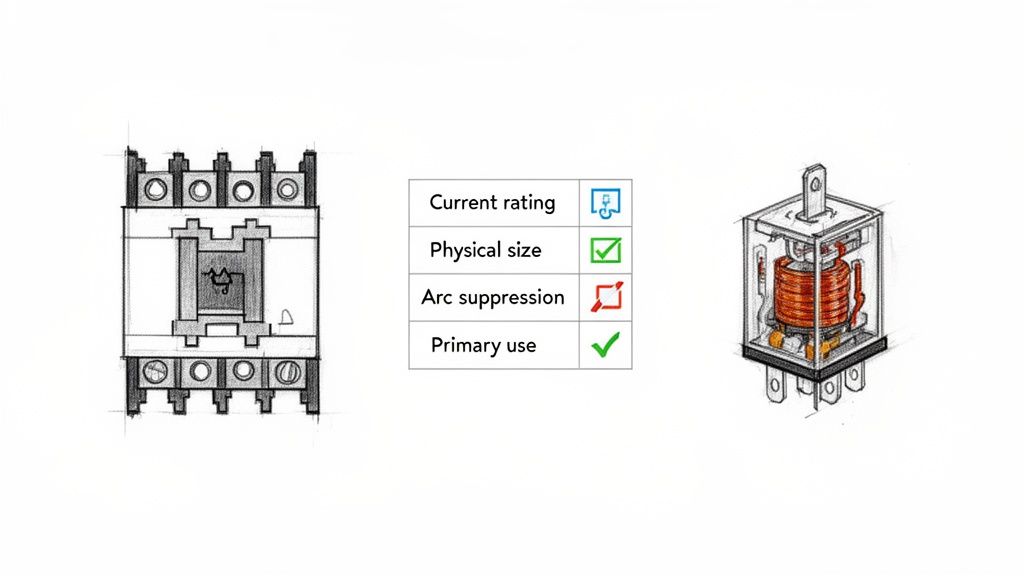
For a quick side-by-side view, this table breaks down the main differences between contactors and relays across the most important characteristics. It's a handy reference for seeing where each device shines.
Switching low-power control signals (PLC outputs, logic)
Physical Size
Large and robust
Small and compact
Arc Suppression
Yes, built-in arc chutes are standard
No, not designed for high-current arcing
Safety Features
Designed for high fault currents and safety
Designed for signal isolation and control logic
Contact Type
Normally Open (NO) is standard for power
Both Normally Open (NO) and Normally Closed (NC) are common
Cost
Higher
Lower
Ultimately, this table reinforces the core idea: contactors are built for power, and relays are built for control. Knowing when to use which is fundamental to sound electrical design.
Exploring The Design and Operating Principles
To really get the difference between a contactor and a relay, you have to look past the fact they both use an electromagnet and dive into how they're built. At a high level, sure, they both use a small electrical signal to switch a bigger one. But crack them open, and you see two totally different philosophies at work.
A contactor is a brute—a fortress built to handle serious power. A relay, on the other hand, is a precision instrument, designed for logic and control. The internal guts of each device tell the whole story.
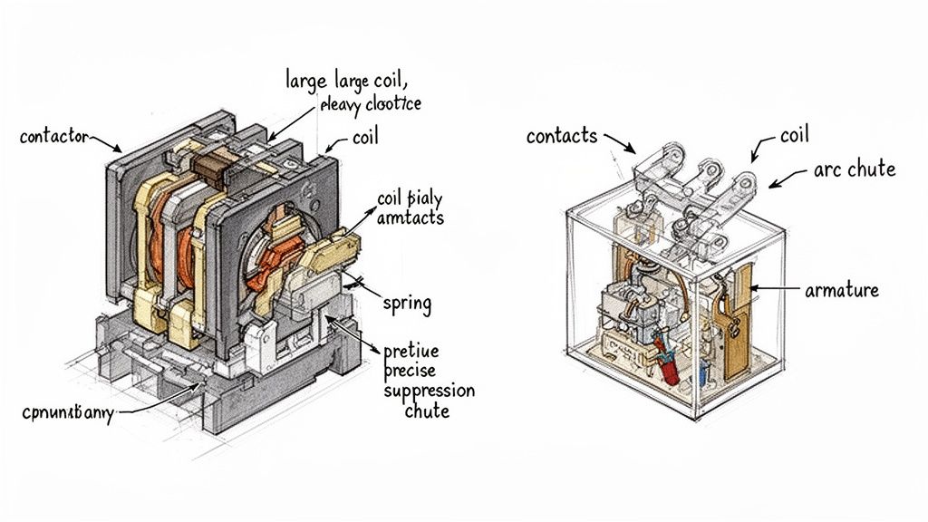
Contactor Construction: Built for Power and Safety
Every piece inside a contactor is beefed up for one reason: survival. The coil is bigger and needs more juice to create a magnetic field strong enough to slam those heavy contacts shut. This powerful action has to overcome some seriously stiff return springs, which are there to make sure the contacts snap open decisively the moment you kill the power. No hesitation.
But the real game-changer is how a contactor handles arc suppression. When you try to break a high-current circuit—especially one feeding a motor—a violent electrical arc jumps across the contacts as they separate. This arc is destructive. To kill it, contactors are armed with a few key features:
Arc Chutes: These are special chambers built around the contacts. They are designed to contain, stretch, cool, and ultimately extinguish the arc before it can weld the contacts shut or start a fire.
Double-Break Contacts: Instead of one big arc, this design creates two smaller, more manageable arcs. It’s a clever way to divide and conquer the electrical energy, making it much easier to snuff out.
Think of a contactor's arc suppression system as its most critical safety feature. It's not just a nice-to-have; it's the core engineering that lets it survive the punishing job of switching heavy, inductive loads day in and day out.
This heavy-duty design is precisely why a contactor can handle the massive 600% to 800% inrush current from a motor starting up and then safely disconnect that power thousands of times over its lifespan.
Relay Design: Optimized for Logic and Precision
Now, look inside a relay. It’s a completely different world. A relay is a model of efficiency, built for finesse in low-power control circuits. We're talking currents typically under 10 amps and much lower voltages. Everything is smaller and more delicate.
The coil is tiny and sips power—often just a few milliwatts—which is perfect for being controlled directly by a PLC or a sensitive electronic circuit. The contacts are small, made from materials that prioritize clean signal transmission, not brute force current handling.
Since relays are only switching small amounts of energy, they don't have to worry about the massive, destructive arcs that contactors face. That means no need for bulky arc chutes or heavy-duty springs. The entire design is focused on being fast, reliable for millions of cycles, and compact enough to cram onto a crowded DIN rail in a control cabinet. For a good look at how these control signals are separated from the main power, you can check out a wiring diagram for lighting contactors.
Ultimately, form follows function. The guts of a contactor—its big coil, heavy springs, and arc chutes—are non-negotiable for safely controlling power. The relay’s minimalist, precise build is perfectly tailored for its job as a signal-level traffic cop. One look inside tells you exactly what each tool was made for.
When you get past the design theory and start looking at the spec sheet, the differences between a contactor and a relay become impossible to ignore. These electrical ratings aren't just abstract numbers; they define the absolute operational limits of each device and tell you exactly where it can be installed safely and reliably.
The biggest distinction, hands down, comes down to the contact ratings—the maximum current and voltage the contacts can actually switch. This one factor tells you almost everything you need to know.
A small, compact relay you might find on a PLC output card could be rated for 5 amps at 240VAC. In stark contrast, a standard industrial contactor for a 25-horsepower three-phase motor will likely be rated for 40 amps at 480VAC. The contactor's entire purpose is built around its ability to handle this kind of power.
Contact Ratings Under Inductive Loads
The real test, however, is switching inductive loads like motors. When a motor kicks on, its inrush current can spike to 6 to 8 times its normal full-load amperage (FLA). A relay rated for 10 amps would be destroyed instantly by the 150-amp inrush from even a small motor. Its contacts would weld themselves shut on the very first try.
This is exactly the kind of abuse contactors are built for. They are often given an AC-3 utilization category rating (an IEC standard), which is a specific certification for starting and stopping squirrel-cage motors. This rating is a guarantee that the contactor can handle the massive inrush current and safely break the locked-rotor current over and over again without failing.
The true value of a contactor is its brute-force ability to survive the punishing cycle of starting and stopping motors. Its heavy-duty contacts and arc suppression systems are engineered to manage electrical stresses that would vaporize a relay in a single operation.
This ruggedness is what maintenance managers count on to minimize downtime and what machine builders rely on to standardize components that they know won't fail in the field.
Coil Characteristics and Control Voltage
Looking at the control side of these components also reveals some key differences. The coil is what gets the signal to actually flip the switch.
Relay Coils: These are designed to sip power, often drawing just a few milliamps at common control voltages like 24VDC. Their efficiency is what allows them to be driven directly from sensitive electronics, like PLC output cards, without any extra hardware.
Contactor Coils: Because they have to slam heavy-duty contacts shut against powerful springs, contactor coils need a lot more juice. You'll find them in a wide range of voltages—24VDC, 120VAC, and 240VAC—to fit into just about any industrial control panel.
That higher power draw from a contactor coil is a practical detail you can't overlook. Sometimes, you'll need to use a small "interposing" relay just to switch the power for the contactor coil, especially if the main control signal from a PLC can't supply enough current on its own.
Switching Capacity and Market Significance
At the end of the day, it's the raw power-handling capacity that truly separates these two. In the world of industrial motor control, contactors are the undisputed heavyweights, a market dominated by major players in electric motors and controls. The global contactor market was valued at USD 1 billion in 2024 and is expected to keep growing, thanks to the relentless push for automation in factories, commercial buildings, and even homes.
This growth underscores the contactor's vital role in running everything from motors and HVAC systems to large-scale lighting and renewable energy systems. These devices can switch loads up to thousands of amps and hundreds of kilowatts—a completely different league from relays, which are typically kept to signaling tasks under 20 amps. For a deeper dive, you can check out recent contactor market growth analysis from industry reports.
This massive gap in switching capacity makes their roles mutually exclusive. A relay is perfect for turning on an indicator light or activating a small solenoid valve. But for a conveyor belt motor or a large industrial heater, a contactor is the only safe and reliable choice. Using a relay in a high-power circuit isn't just a design mistake; it's a serious safety hazard that will lead to catastrophic equipment failure.
Choosing The Right Component for Your Application
Knowing the technical specs is one thing, but making the right call in a complex industrial environment is where the real expertise comes in. The choice between a contactor and a relay isn't just about voltage or amperage ratings; it's about understanding the nature of the load and the demands of the system you're building or maintaining.
A good rule of thumb to start with is this: if you're switching a significant power load, especially an inductive one like a motor, a contactor should be your default choice. For low-power control signals, logic circuits, or small resistive loads, a relay is almost always the smarter, more efficient option. Getting this wrong isn't just inefficient—it's a fast track to premature component failure and serious safety hazards.
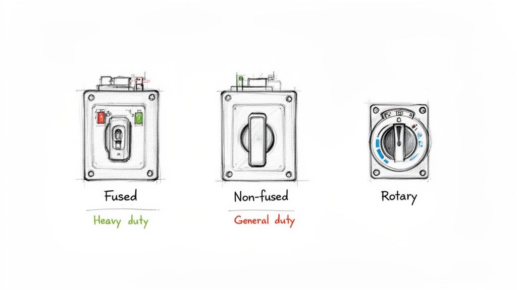
When to Specify a Contactor
Contactors are the heavy-duty workhorses of industrial power. They are engineered from the ground up for durability and safety under immense electrical stress. Their beefy construction and built-in arc suppression features make them the only real choice for demanding, high-current jobs.
You should always be reaching for a contactor in these classic industrial scenarios:
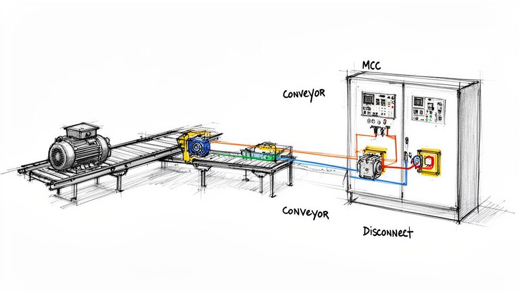
Motor Control Centers (MCCs): This is the bread-and-butter application. A contactor is the heart of a motor starter, built to handle the brutal inrush current of three-phase motors that run conveyors, pumps, and heavy machinery. To see how they fit into the complete assembly, check out our guide on what a motor starter is and does.
Large HVAC Systems: Think commercial and industrial systems. The powerful compressors, massive fans, and heavy heating elements in these units require contactors to reliably switch high-amperage loads, often through millions of cycles.
Industrial Heating Elements: Large-scale industrial ovens, furnaces, and process heaters draw an enormous amount of current. A contactor provides the raw switching capacity needed to control these resistive loads safely without contacts welding shut or overheating.
Heavy-Duty Lighting Circuits: When you need to control entire banks of high-wattage lights in a warehouse, stadium, or parking lot from a single point, a contactor is the tool for the job. It’s built to handle the significant inrush current that these lighting arrays produce.
When a Relay Is the Right Choice
Relays bring precision and efficiency to control-level circuits. Their compact size, low power consumption, and quick switching speeds make them perfect for tasks where finesse is more valuable than brute force. Think of them as the nervous system of an automation panel, translating low-power digital commands into real-world actions.
A relay is your best bet for applications like these:
PLC Control Logic Isolation: Relays are often used as "interposing" devices. They sit between a PLC's sensitive, expensive digital output card and the field device it needs to control, isolating the PLC from damaging voltage spikes or feedback.
Interlocking Safety Circuits: In safety systems, relays are essential for creating logic that prevents dangerous situations. For example, a relay can ensure a machine guard is securely closed before allowing a motor to start.
Switching Small Devices: Relays are perfectly suited for activating low-power components like solenoid valves, indicator lights on a control panel, small cooling fans, or audible alarms.
The decision between a contactor and a relay is a direct reflection of the application's demands. A high-cycle conveyor system needs the durability of a contactor, while a simple alarm panel requires the low-power precision of a relay. Matching the component to the task is fundamental for operational reliability.
Looking at market trends, you can see these distinct roles reflected in the numbers. The global contactor and relay market is projected to grow from USD 3.5 billion in 2024 to USD 6.5 billion by 2033, with a big push from industrialization in the Asia-Pacific region.
This data shows a clear divide: contactors are dominating in high-power projects like MV switchgear and EV charging infrastructure, while relays are the go-to for signal-level applications in aviation and telecom. You can discover more insights on the contactor and relay market trends to see this evolution. By understanding these specific roles, you can build systems that are not just functional but also safe, efficient, and cost-effective.
Lifespan, Standards, and Why Safety Can't Be Ignored
In any industrial plant, reliability isn't just a goal—it's a requirement. When a component fails, you’re looking at expensive downtime and potentially dangerous situations. This is where the conversation about contactors versus relays gets serious, moving beyond simple specs to operational lifespan and safety standards. These numbers aren't just for data sheets; they directly inform your total cost of ownership and your entire preventive maintenance strategy.
The core difference in their construction dictates how long they last and under what conditions. Contactors are engineered for the long haul, built to withstand heavy electrical and mechanical abuse. Relays, on the other hand, are designed for a high volume of switching cycles, but only with lighter loads.
Mechanical vs. Electrical Lifespan: What Really Matters
When you see a "lifespan" number, you need to ask: is that mechanical or electrical? It’s a critical distinction.
Mechanical lifespan is the number of times a device can switch with no power running through it. Think of it as a stress test for the moving parts. Electrical lifespan measures how many cycles it can handle while switching its fully rated load, which is the true test of its real-world durability.
Contactors: These brutes often have a mechanical lifespan of 10 to 20 million cycles. But the real story is their electrical lifespan, which can exceed 1 million cycles even under a full AC-3 motor load.
Relays: They look impressive on paper with a mechanical lifespan that can top 50 million cycles. Dig deeper, though, and you’ll find their electrical lifespan, even at their much lower rated current, is often between 100,000 and 500,000 cycles.
This is a huge deal. A contactor's ability to break a heavy, angry inductive load over a million times is a direct result of its tough build and integrated arc suppression. That kind of durability means more uptime and fewer component swaps in your most important machinery. To get a better handle on this, it helps to understand the fundamentals of the protection of motors in these demanding environments.
The Critical Role of Safety Standards in Your Choice
Picking the right component isn't just a performance decision; it's a matter of safety and compliance. Major standards from Underwriters Laboratories (UL) and the International Electrotechnical Commission (IEC) set the rules for a reason. Ignoring them can lead to fried equipment, serious safety risks, and failing an inspection.
History and hard data have proven the superiority of contactors in industrial applications, which is a key factor for anyone building custom UL control panels. Contactors, which have been around since the early 1900s, are built to manage currents from 10A all the way up to 5000A, with a typical lifespan of 1 to 10 million cycles. Relays are in a different league, usually handling 5-10A with a lifespan of 100,000 to 1 million cycles. The presence of arc chutes in contactors is a game-changing safety feature, allowing them to safely switch high voltages and reducing failures by 30-50% in harsh settings where a relay’s contacts would be prone to welding shut.
When you're designing a control panel, following standards like UL 508A isn't optional—it's mandatory for certification and safety. This standard explicitly guides component selection based on the load, ensuring a robust device like a contactor is used for motor control where its safety features are absolutely essential.
A few key standards you should always have on your radar:
UL 508 (Industrial Control Equipment): This is the bible for North American industrial control panels, covering components like contactors, motor starters, and relays.
IEC 60947 (Low-Voltage Switchgear and Controlgear): The international equivalent, with specific sections for different devices. For instance, IEC 60947-4-1 lays out the requirements for contactors.
Choosing a component certified to these standards means it's been through rigorous testing and has the built-in safety mechanisms for its intended job. Ultimately, the choice between a contactor and a relay isn't just technical—it's a critical safety decision.
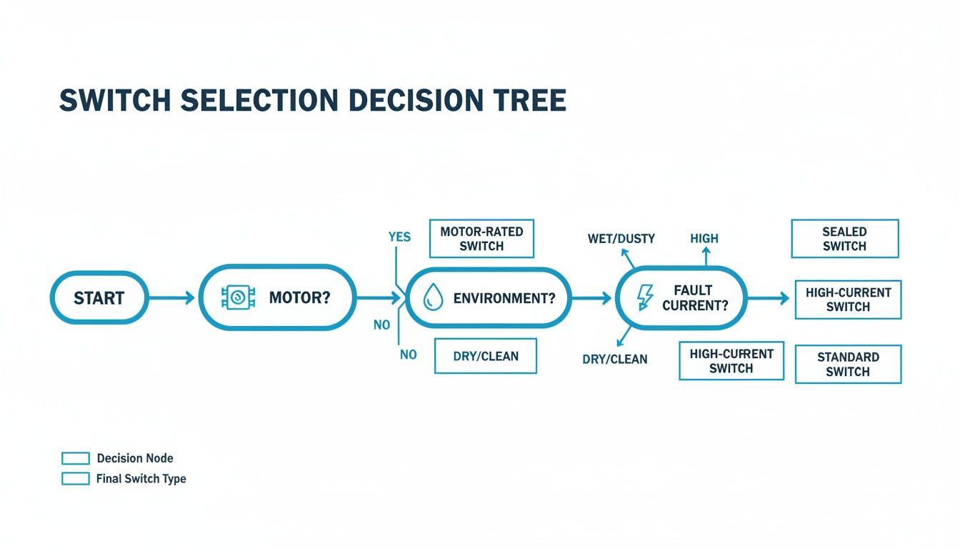
A Practical Selection Checklist
Trying to decide between a contactor and a relay? It all comes down to asking the right questions. Getting this choice right is about more than just making the circuit work—it’s about building a system that’s safe, reliable, and up to code. This checklist boils down the key differences into a straightforward framework to help you make the right call.
If you work through these questions logically, you’ll be able to specify the right component for the job, every time. The process starts with the most critical factor—the load itself—before moving on to other important details like your control logic and how the system will be used day-to-day.
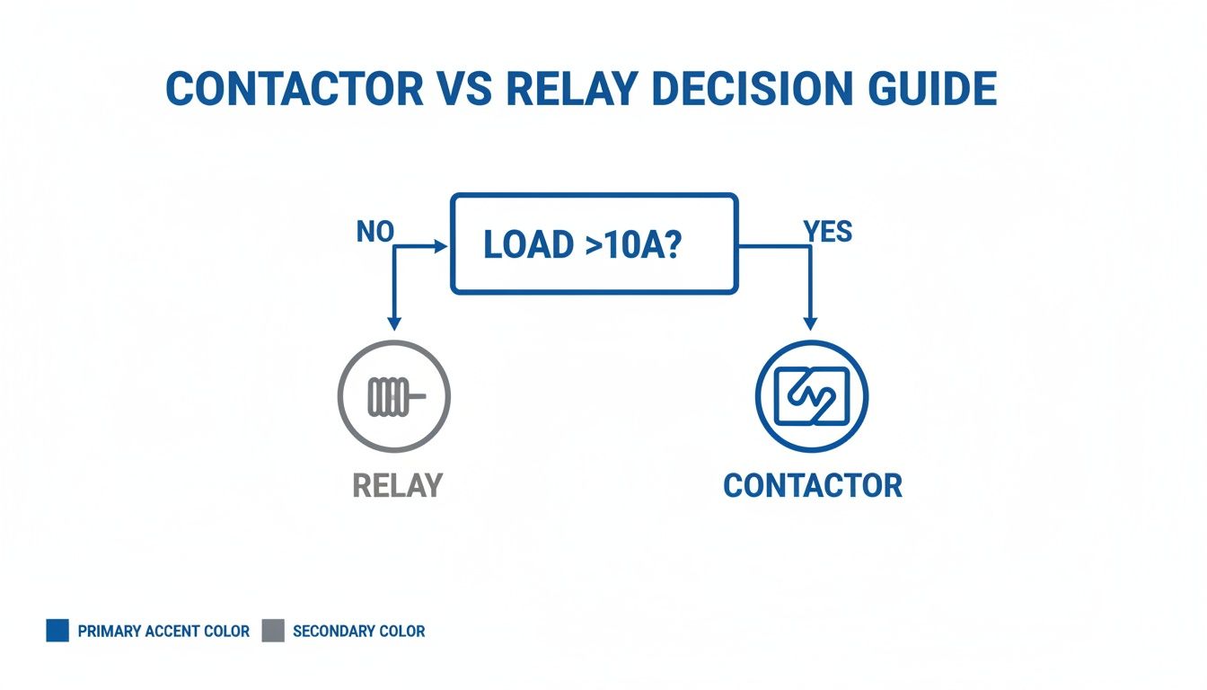
This simple chart gets right to the heart of the matter.
As you can see, that 10-amp line is the first major fork in the road. It immediately points you toward a contactor for power switching and a relay for control signals.
Load Characteristics
The nature of the electrical load is, without a doubt, the most important piece of the puzzle. Answering these two questions will narrow down your options fast.
What’s the full-load amperage (FLA)? If the steady current draw is over 10A, a contactor is almost certainly the answer. Relays are best kept to loads comfortably below that mark.
Is the load inductive or resistive? Inductive loads—think motors, transformers, or solenoids—are tough on switching components. They create huge inrush currents and nasty electrical arcs. Contactors are built for this abuse, with features like arc suppression. Relays, on the other hand, are much happier switching simple resistive loads like heaters or lights.
You can think of this choice as a risk assessment. A contactor is engineered to handle the risks that come with switching powerful, inductive loads. A relay is built for the low-risk world of signal-level logic. Using the wrong one is an open invitation to equipment failure and serious safety hazards.
System and Control Requirements
Beyond the load, you need to think about how this component fits into the bigger picture of your control system.
What control voltage is available? Make sure the coil voltage of your device (whether it's 24VDC, 120VAC, etc.) matches the output from your PLC or whatever is driving it. Contactor coils generally need more power to pull in than relay coils, which sometimes means you’ll need a small interposing relay just to activate the contactor.
Do you need auxiliary contacts for feedback? If your control logic needs to confirm that a motor has actually started, or if you need a signal for a safety interlock, you’ll want a contactor. They are designed with built-in or add-on auxiliary contacts specifically for this kind of feedback. While a standard relay might have multiple contacts (Form C), they aren't meant for feeding status back from a power circuit.
Operational Demands
Finally, look at the long-term operational needs to make sure the component you choose will last.
How often will it be switching? For high-cycle applications that are turning on and off many times per minute, the heavy-duty mechanical construction of a contactor is a must if you want it to have a long service life.
What’s the required electrical lifespan? Always check the manufacturer’s datasheet for the electrical life rating at your specific load current. A contactor is designed to survive over a million cycles switching a heavy motor, a number that a relay would never come close to in the same high-stress job.
Answering Your Lingering Questions
Even after laying out the core differences, a few common questions always pop up when it's time to apply these components in the real world. Let's tackle some of the most frequent ones to clear up any confusion and give you some practical answers for your next project.
Can I Use a Contactor Instead of a Relay?
Technically, yes. You could use a contactor to switch a tiny load that a relay would normally handle. But you really shouldn't.
It’s almost always a bad idea. The contactor will be bigger, cost more, and its coil will pull way more power than a relay's coil ever would. While it's a safe substitution, it’s not an efficient one. Using a contactor where a relay belongs is a classic case of over-engineering the solution.
What Happens If I Use a Relay to Control a Motor?
This is where things get dangerous. Putting a standard relay on a motor is a recipe for catastrophic failure, guaranteed. A relay's contacts just aren't built for the massive inrush current a motor draws at startup—often 6 to 8 times its normal running amps.
That huge surge of current creates a powerful arc that will instantly weld the relay contacts together. When that happens, you've created a nightmare scenario where the motor can't be shut off, putting both your equipment and your team at serious risk.
Never, ever substitute a relay for a contactor in a motor circuit. The lack of arc suppression and the wrong contact material will cause an immediate and unsafe failure. This is the critical difference between these two components.
What Are Auxiliary Contacts on a Contactor Used For?
Auxiliary contacts are the contactor’s sidekick. They are smaller, low-power contacts that are physically linked to the main power contacts but are electrically separate. They open and close right along with the main contacts, but they're strictly for control logic, not for switching the heavy load.
You'll see them used for a few key jobs:
Status Feedback: Sending a signal to a PLC to confirm that the contactor has pulled in and the motor is actually running.
Safety Interlocks: Preventing another contactor from turning on at the same time, like in a forward/reverse motor starter.
Indicator Lights: Lighting up a lamp on a control panel to give operators a visual cue about the machine's status.
Are There Smart Contactors and Relays?
Absolutely. Intelligent versions of both have been making their way into modern industrial setups. Smart contactors, in particular, are becoming a staple in Industry 4.0 applications. They often come with built-in electronic overload protection, communication protocols like EtherNet/IP, and diagnostic capabilities that monitor current and temperature for predictive maintenance.
While you can find smart relays with advanced timing and logic functions, the push towards integrated intelligence is much stronger with contactors. It makes sense—they're protecting high-value assets like motors, so the extra insight is well worth it.
For over 50 years, E & I Sales has been the trusted partner for industrial system integrators, plant managers, and OEMs, providing not just components but complete, reliable solutions. From premium electric motors to custom-engineered UL control panels, we ensure your operations are safe, efficient, and built to last. Partner with us to standardize your equipment and accelerate your projects with confidence. Learn more about our expertise at https://eandisales.com.
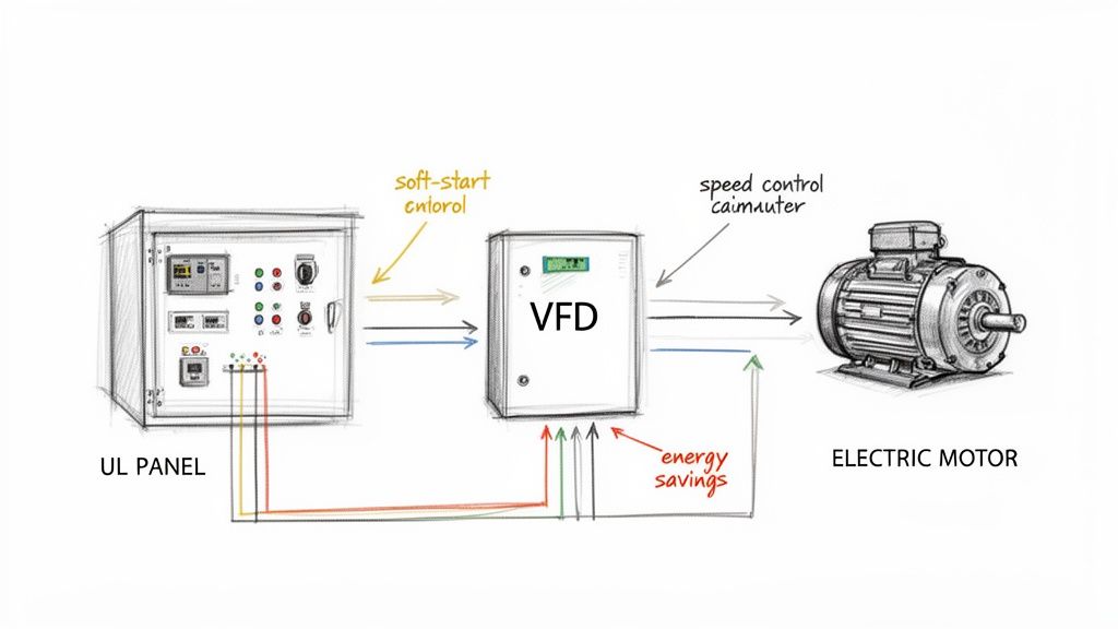
Think of it less like an on/off switch and more like the accelerator pedal for an industrial motor. Instead of just slamming the motor on or off, a VSD (often called a variable frequency drive, or VFD) gives you precise, granular control by adjusting the electrical frequency and voltage feeding the motor.
It’s the key to unlocking a whole new level of efficiency and control in modern industry.
Why VSDs are a Game-Changer
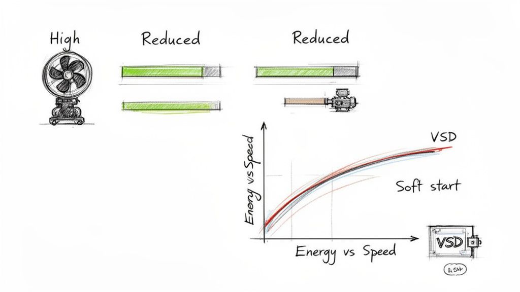
Picture this: you have a massive industrial fan, and your only control is a simple switch. It's either off or running at 100% power—no in-between. This all-or-nothing approach is incredibly wasteful and puts a ton of mechanical stress on your equipment every single time it lurches into action.
Now, imagine having that accelerator pedal. You can gently ramp up the speed, dial it in to the exact level needed for the job, and then smoothly ramp it down. That’s the power a VSD brings to the table.
For plant engineers, OEMs, and system integrators, a VSD isn't just another piece of hardware. It's a strategic tool for solving some of the biggest operational headaches. They are absolutely essential for:
Dialing in Performance: VSDs let you match motor speed perfectly to the process demand, giving you unmatched control over applications like pumps, fans, and conveyors.
Slashing Energy Costs: Why run a motor at full blast and then use a valve to choke the flow? It's like flooring the gas in your car while riding the brake. A VSD simply slows the motor down, resulting in massive energy savings.
Making Equipment Last Longer: That jarring, across-the-line start is brutal on machinery. A VSD’s "soft start" capability eliminates that mechanical shock, reducing wear and tear on belts, gears, and bearings.
A VSD changes equipment speed to provide the torque-energy input needed to supply the hydraulic-energy output to the process. The most efficient means of flow manipulation is pump-speed adjustment, which reduces pressure imparted to the fluid and, in return, reduces power consumption.
A Market Driven by Smarter Operations
Adopting VSDs isn't just a trend; it's a fundamental shift in how industries think about motor control. The global VFD market hit USD 28.38 billion in 2024, a clear sign of just how vital this technology has become in manufacturing, HVAC, and material handling.
And it’s not slowing down. That market is expected to climb to USD 39.67 billion by 2030, all thanks to the relentless push for better energy efficiency and lower operating costs.
With over 300 million motors running in industrial settings worldwide, the potential for improvement is staggering. For anyone involved in industrial capital projects, understanding this technology is no longer optional—it's how you stay competitive. You can read the full research about VFD market growth to see the numbers for yourself. This is about more than just a component; it's about a smarter, leaner way to power your operations.
How a Variable Speed Drive Actually Works
So, how does one of these drives actually get the job done? While the inner workings involve some pretty complex electronics, the core concept is refreshingly simple.
Think of a VSD as a power conditioning expert for your motor. It takes the raw, fixed "one-size-fits-all" power from the utility grid and meticulously reshapes it into the perfect, custom-tailored power your motor needs to run at any given speed.
This whole transformation happens in three key stages. Let's imagine you're managing a water supply: the AC power coming in is like a wild, unpredictable river, but your motor needs a perfectly steady and controlled flow to work right. The VSD is the sophisticated dam and valve system that tames that river.
Stage 1: The Rectifier – Taming the Current
First up, the incoming power hits the rectifier. Its only job is to take the alternating current (AC) from the grid and convert it into direct current (DC). In our water analogy, the rectifier is like a dam with a series of one-way gates (diodes) that capture the river's chaotic flow and funnel it into a large reservoir.
A typical three-phase VSD uses six of these diodes, two for each electrical phase. As the AC sine wave for each phase swings from positive to negative, the diodes open and close, letting only the positive voltage pass through. This creates a rough, pulsating DC voltage—like waves filling our reservoir.
Stage 2: The DC Bus – Smoothing Things Out
Once converted, that pulsating DC power flows into the DC bus. This is our reservoir. Its key components are large capacitors that act like shock absorbers, smoothing out the ripples from the rectifier. The capacitors store this electrical energy, soaking up the peaks and filling in the troughs.
What you're left with is a clean, stable DC voltage, primed and ready for the final step. It's worth noting that the voltage here is usually higher than what came in; for a 480V AC system, you'll often see around 650V DC on the bus. This stable reserve of power is absolutely vital for the drive's performance.
At its heart, a VSD is a power manipulator. It converts incoming AC power to a stable DC form, then flips that DC back into a brand new, perfectly controlled AC waveform. This gives you precise control over both the frequency and voltage sent to the motor.
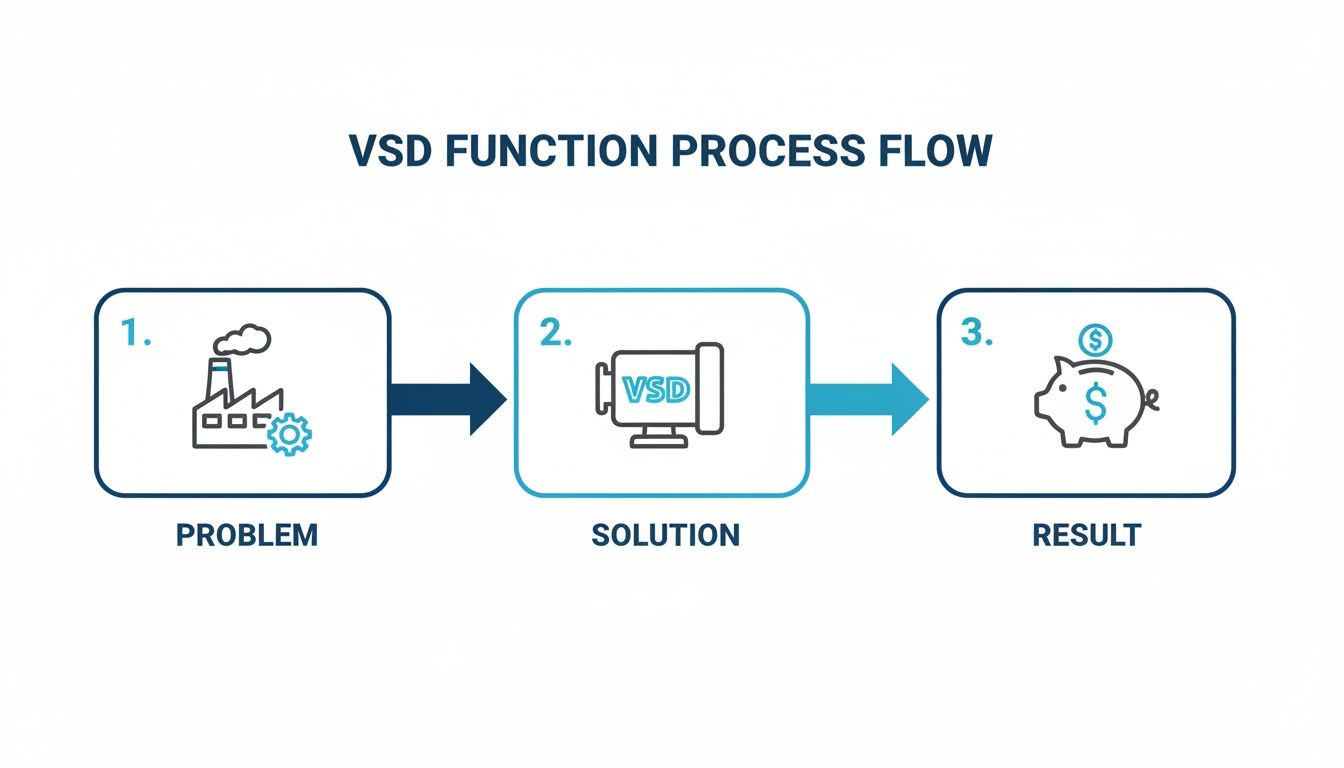
This simple flow shows how a VSD translates a common factory problem into a real, tangible cost-saving solution.
The path from the factory to the piggy bank makes it clear—this technology has a direct and positive impact on your bottom line.
Stage 3: The Inverter – Building the Perfect Waveform
The final and most critical stage is the inverter. This is where the magic really happens. The inverter takes that smooth DC power from the bus and skillfully converts it back into a variable AC output for the motor. Think of it as a set of highly advanced, computer-controlled valves on our reservoir, releasing water in precise, rapid-fire pulses to create a completely new, custom-designed river flow.
This section is built around powerful electronic switches, usually Insulated-Gate Bipolar Transistors (IGBTs), that can flip on and off thousands of times per second. By controlling the exact timing and duration of these pulses, the VSD constructs a simulated AC sine wave. This technique is known as Pulse Width Modulation (PWM).
What does this three-stage process give you?
Total Speed Control: By changing how fast the IGBTs switch, the inverter creates any frequency it wants. Since an AC motor's speed is tied directly to frequency, you now have complete control.
Optimized Voltage: By adjusting the width of the pulses (how long the switches stay on), the drive dials in the perfect output voltage, ensuring the motor gets just the right amount of power for any speed.
Pinpoint Precision: This ability to build a perfect AC waveform from scratch gives you unparalleled command over your motor's acceleration, deceleration, and running speed.
By mastering this AC-to-DC-to-AC conversion, a VSD turns a simple AC motor into a highly precise and incredibly efficient machine. To explore these foundational concepts further, check out our guide on variable frequency drive basics. This process is the secret behind a VSD's power and effectiveness.
What VSDs Actually Do for You on the Plant Floor
It’s one thing to understand the theory behind a variable speed drive, but it’s another thing entirely to see what it can do for your operation. This is where the real value hits home. The benefits go way beyond just changing a motor's speed—they deliver real, measurable returns that you can take to the bank.
Two advantages, in particular, are total game-changers for any industrial facility: massive energy savings and far superior process control. For any plant manager or engineer focused on the bottom line, these benefits are impossible to ignore. They offer a direct line to lower operating costs and a more reliable, productive plant.
Slashing Your Energy Bills
If there’s one single reason to get on board with VSDs, it’s the incredible potential for energy savings. Motor-driven systems are energy hogs, often accounting for 25% to 50% of a facility's total electricity bill. The old way of controlling a pump or fan was to run the motor at full tilt and then use a damper or valve to choke back the flow. It’s a brutally inefficient method.
Think of it like driving your car with one foot slammed on the gas and the other on the brake just to manage your speed. It's pure waste.
A VSD gets rid of that waste by simply slowing the motor down to match the exact demand. This is where the Affinity Laws for fans and pumps come into play, and they reveal a powerful truth about the relationship between speed and power. These laws show that a motor's power draw varies with the cube of its speed.
What does that cubic relationship mean? It means even a small drop in motor speed creates a huge drop in energy use. For instance, slowing a fan's speed by just 20% (to 80% of its max) can slash its energy consumption by nearly 50%.
That’s the secret sauce. Instead of fighting a full-speed motor, you’re only ever using the precise amount of power you need. This doesn't just cut your electricity bills; it shrinks your carbon footprint, helping you hit sustainability targets while boosting your bottom line. You can dig deeper into the numbers in our full guide on how VFDs generate substantial energy savings.
Extending Equipment Life Through Gentle Control
Beyond saving money on power, VSDs are just plain kinder to your equipment, reducing mechanical stress and making everything last longer. A standard motor starts "across-the-line," which means it gets hit with a massive, instant jolt of full voltage and current. It’s like hitting your machinery with a sledgehammer every time it starts up.
This sudden inrush of current—often 600% or more of the motor's normal running current—sends a shockwave of torque through the entire system, causing all sorts of wear and tear.
A VSD, on the other hand, provides a "soft start." It gently ramps the motor's speed up from a standstill to its target. This smooth acceleration eliminates the mechanical shock that destroys:
Belts and Couplings: Prevents them from stretching, slipping, and failing prematurely.
Gears and Gearboxes: Reduces the harsh stress on gear teeth and internal parts.
Bearings: Minimizes the impact that leads to pitting and eventual failure.
Piping Systems: Stops "water hammer" and other hydraulic shocks in fluid systems.
This gentle handling means less maintenance, fewer surprise breakdowns, and a longer, more predictable life for your most critical assets. The reduction in downtime alone is often enough to justify the investment in a drive.
Achieving Pinpoint Process Control
Finally, VSDs give you a level of precision that mechanical controls can't even dream of. By allowing you to make exact speed adjustments, a drive can fine-tune a process to boost quality, cut down on waste, and improve consistency across the board.
The table below breaks down how this plays out in a few common scenarios.
VSD Benefits Across Industrial Applications
Application Area
Primary Benefit
Operational Impact
HVAC & Pumping Systems
Energy Efficiency
Dramatically reduces power consumption by matching fan/pump speed to real-time heating, cooling, or flow demands.
Conveyor Systems
Synchronization
Ensures precise speed matching between different sections of a production line, preventing bottlenecks and material damage.
Mixers & Agitators
Product Quality
Allows for variable mixing speeds to achieve perfect consistency for different recipes or batch phases.
Winders & Unwinders
Tension Control
Maintains constant tension on materials like paper, film, or wire, preventing stretching, snapping, and waste.
This kind of control is invaluable in any application that needs to be just right. By integrating a VSD, you’re turning a dumb, fixed-speed motor into an intelligent, responsive part of your operation. You get better products, less waste, and a more agile facility all around.
How to Select the Right Variable Speed Drive
Picking the right variable speed drive isn’t as simple as matching the horsepower on the motor's nameplate. To get it right, you really have to dig into the details of the motor, the job it's doing, and the environment it lives in. Nailing these specifics is the key to a drive that performs reliably and safely for the long haul.
Get this part wrong, and you’re looking at nuisance trips, fried equipment, or worse. A systematic approach helps you specify a VSD that’s a perfect match for your application, saving you from costly mistakes and frustrating downtime. It’s all about building a solid, dependable motor control system from the ground up.
Match the Drive to Your Motor
First things first: look at the motor. Not all motors play nice with VSDs, and hooking one up to a motor that isn't ready for it is just asking for trouble. The simulated AC waveform a VSD creates—with its rapid-fire voltage pulses—is incredibly tough on standard motor windings.
This is exactly why you need to check if your motor is inverter-duty rated. These motors are built with beefed-up insulation systems designed to handle the high voltage spikes and fast switching that VFDs throw at them. If you use a standard motor, you risk the insulation breaking down and shorting out the motor way ahead of its time.
Once you’ve confirmed the motor’s rating, you need to grab some key data off the nameplate to program the drive correctly:
Full Load Amps (FLA): This is non-negotiable. The drive’s continuous current rating absolutely must be higher than the motor's FLA.
Voltage and Frequency: Make sure the drive’s voltage matches your system (like 480V) and the motor’s design frequency (usually 60 Hz in the US).
Motor Speed (RPM): This helps the drive dial in the V/Hz pattern for the best possible performance.
Analyze Your Application Load Profile
Next up, what kind of work is this motor actually doing? Different jobs put different demands on a motor, and VSDs are built to handle them differently. The two big categories you'll hear about are variable torque and constant torque.
A variable torque (VT) load is what you see with centrifugal pumps and fans. With these, the torque needed to spin the equipment skyrockets as the speed increases. Since you rarely need full muscle at low speeds, a VT-rated drive is the perfect, most economical choice.
On the flip side, a constant torque (CT) load needs pretty much the same amount of torque whether it's crawling or running full out. Think of a conveyor belt or a positive displacement pump. These applications need a drive with a much more robust overload capacity to handle that heavy lifting, especially at startup and low speeds. Luckily, many modern drives are dual-rated, so you can just select VT or CT mode during setup.
This choice is critical. A variable torque drive is a smart, cost-saving move for a fan, but putting that same drive on a heavy-duty conveyor is a recipe for constant overload faults and a system that just won't run.
Consider the Operating Environment
Where is this VSD going to live? The physical environment is a huge factor in a drive's lifespan and safety. You have to choose a drive with the right NEMA (National Electrical Manufacturers Association) enclosure rating to shield its sensitive electronics.
A NEMA 1 enclosure is fine for a clean, dry control room. But if the drive will be out on the floor where there’s dust or a risk of light splashing, you’ll need to step up to a NEMA 12 enclosure. And for places that get regular washdowns, like in food processing, a NEMA 4X enclosure is a must to protect against corrosion and high-pressure water.
Don’t forget about air. VSDs kick off a lot of heat, and overheating is one of the top reasons they fail. Make sure the spot you choose has enough airflow around the drive's heatsink, and always follow the manufacturer's specs for clearance space.
Address Power Quality Concerns
Finally, be aware that a VSD can introduce electrical "noise"—also known as harmonics—back into your power system. This can mess with other sensitive electronics in your facility. For big VSD installations, you might need a full-blown harmonic study, but for most smaller drives, there's a simple fix: a line reactor.
A line reactor is basically a big coil you install on the input side of the VSD. It helps smooth out the current the drive pulls from the line, which cuts down on harmonic distortion. It also adds a great layer of protection for the VSD against voltage spikes from the power grid. It's a cheap piece of insurance that adds a ton of stability.
While a VSD is great at managing motor acceleration, sometimes you might be interested in a different approach. You can learn more about what is a soft starter in our detailed guide.
Best Practices for VSD Installation and Commissioning
A top-of-the-line variable speed drive is only as good as its installation. You can have the best drive in the world, but without a solid installation and a methodical startup, you’re setting it up for premature failure. Getting these foundational steps right is non-negotiable for anyone looking to build a reliable system.
Frankly, even the most advanced VSD is vulnerable to common, everyday issues on the plant floor. A proper installation isn't just about hooking up wires; it’s about creating a stable home for the drive to do its job. That means paying just as much attention to electrical noise, heat, and physical placement as you do to the power connections.
Core Installation Guidelines
Before you even think about flipping the switch, a few installation basics will prevent the vast majority of problems down the line. Think of this as laying the groundwork. Time and again, we see nuisance trips and early component failures that trace back to skipping these simple but critical steps.
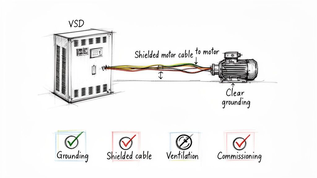
First and foremost, proper grounding is your number one defense against electrical noise. The high-speed switching inside a VSD is powerful, but it can create interference that messes with other sensitive equipment. A solid, low-impedance ground gives that noise a safe path away from everything else.
Next, you absolutely must use shielded motor cables. That cable running between the VSD and the motor is basically a giant antenna broadcasting electrical noise. Shielded VFD cable traps that interference, but only if you ground the shield correctly at both the drive and the motor.
Finally, you have to deal with heat. VSDs get hot, and cooking a drive with poor ventilation is one of the fastest ways to kill it. Always follow the manufacturer's clearance specs to give it breathing room. Getting cool, clean air flowing across the heatsink is the key to a long service life.
A Methodical Commissioning Process
Once the drive is installed right, it's time for commissioning—the startup. This is where you teach the drive how to play nice with your motor and application. Rushing this part is a classic mistake that leads to poor performance or, even worse, damaged equipment.
Follow these key steps for a startup that won't give you headaches later:
Initial Power-Up Checks: Before you go live, double-check that your input voltage is correct and every single connection is tight. A loose wire can cause arcing and catastrophic failure.
Enter Motor Nameplate Data: This is the most important part of programming. You have to accurately punch in the motor’s Full Load Amps (FLA), voltage, RPM, and horsepower. The drive uses this info for all its motor protection and control logic.
Perform an Autotune: Nearly all modern drives have an autotune function. Use it. This lets the VSD "learn" the motor's unique electrical profile, which allows it to build a super-accurate model for the best possible torque and current control.
Set Ramps and Speed Limits: Program your acceleration and deceleration times to match what the machine needs. A smooth ramp-up is easier on your mechanics, and setting min/max speed limits protects your process from running too fast or too slow.
Commissioning is not just about making the motor spin. It's about fine-tuning the drive to the specific load, ensuring the system runs efficiently, reliably, and safely under all operating conditions. Skipping steps here will lead to problems down the road.
When you put in the time for a thorough installation and a systematic startup, you’re building a foundation for a truly robust VSD system. That initial effort pays for itself many times over with less downtime, better performance, and a longer life for your entire system.
Keeping Your VSD System in Top Shape
A VSD that's installed properly is designed to go the distance, but like any piece of high-performance gear, its real-world reliability comes down to smart maintenance and quick troubleshooting. A little bit of proactive attention can make all the difference. In fact, a simple, repeatable maintenance routine is your best bet for preventing the most common failures and keeping your operations humming along without costly surprises.
And when problems do pop up? Knowing how to quickly read the drive's fault codes is the key to slashing downtime. Instead of playing a guessing game, you can let the VSD's own diagnostics point you straight to the issue. This guide is your playbook for doing both.
A No-Nonsense Preventive Maintenance Checklist
Think of regular inspections as your first line of defense. Most VSD issues don’t just happen out of the blue; they build up over time. Catching them early is how you avoid a full-blown breakdown down the road.
A good PM plan doesn't have to be complicated. It really just needs to focus on the three biggest enemies of any VSD: heat, contamination, and loose connections.
Here’s a simple checklist to get you started:
Look Around: Make a habit of visually checking for signs of overheating—things like discolored components or wiring. You'll also want to make sure the drive's internals are clean and free of dust, debris, or any moisture that could cause a short.
Check Your Connections: Vibration and normal heating and cooling cycles can work electrical connections loose over time. Get in there and routinely confirm that all the terminal screws for both power and control wiring are snug. A loose connection is just an arc waiting to happen.
Keep an Ear on the Fan: The cooling fan is absolutely critical. Listen for any weird noises, and make sure it’s spinning freely. A failing fan is one of the most common reasons for overheating, which is hands-down the #1 killer of VSDs.
What Your VSD Is Trying to Tell You: Common Fault Codes
When a VSD trips, it's not actually failing—it's doing its job by protecting itself and your motor. That fault code flashing on the display is an incredibly valuable clue. Understanding what these codes mean is the first step to becoming a troubleshooting pro.
A classic troubleshooting scenario is an overvoltage fault that happens during deceleration. This almost always means the motor is acting like a generator and pushing too much voltage back into the drive. The fix is often as simple as increasing the ramp-down time or adding a dynamic braking resistor.
Let's break down two of the most common faults you'll run into:
Overcurrent (OC): This code pops up when the drive detects a current spike that goes above its rated limit.
What's a Likely Cause? It could be a sudden, heavy change in the load, a short circuit somewhere in the motor or its cabling, or an acceleration ramp that’s just too aggressive for the application.
What Should You Do? Start by inspecting the motor wiring for any damage. Then, check the equipment being driven for any mechanical binding or jams. If everything looks good, try increasing the acceleration time to give the motor a smoother start.
Overvoltage (OV): This fault means the DC bus voltage inside the drive has climbed above its safe operating level.
What's a Likely Cause? Sometimes it's due to high incoming line voltage from the utility, but more often, it's caused by the rapid deceleration of a load with a lot of inertia (like a heavy fan or flywheel).
What Should You Do? First, measure your incoming AC voltage to make sure it’s within the drive's specified range. If the fault only happens during ramp-down, simply increase the deceleration time. For applications that genuinely need fast stops, you'll probably need to install a dynamic braking resistor to burn off that excess energy.
Got Questions About Variable Speed Drives? We’ve Got Answers.
Let's wrap up by tackling a few of the questions we hear all the time when folks are planning a VSD project. Getting these details straight can clear up a lot of confusion and make your implementation much smoother.
Can I Slap a VSD on Just Any Old Motor?
Not if you want it to last. Your standard, off-the-shelf motor just isn't built to handle the unique electrical stress from a VSD. The drive's high-frequency voltage pulses can eat away at the motor’s winding insulation over time, leading to premature failure.
For reliable, long-term operation, you absolutely need an inverter-duty rated motor. These are specifically designed with beefed-up insulation systems that can take the punishment.
What's the Real Difference Between a VSD and a VFD?
You'll hear these terms thrown around a lot, and honestly, they're often used to mean the same thing in the context of AC motors. VFD, or Variable Frequency Drive, is the more precise term because it describes how the drive controls speed—by changing the frequency of the power sent to the motor.
VSD, or Variable Speed Drive, is a broader umbrella that can also cover DC drives or other methods of speed control. But let's be practical: in today's industrial world, if someone says VSD, they're almost certainly talking about a VFD.
How Much Energy Can I Really Save with a VSD?
The potential here is huge, especially for fan and pump systems. It all comes down to a neat bit of physics called the Affinity Laws, which state that power consumption is tied to the cube of the motor's speed.
What does that mean in the real world? It means a small tweak in speed leads to a massive drop in energy use. For instance, dialing back a fan’s speed by just 20% can slash its energy consumption by nearly 50%. That's how you get a quick payback on your investment.
Do I Always Need a Line Reactor?
While it might not be strictly mandatory for every single installation, think of a line reactor as cheap insurance for your drive. We highly recommend it.
A reactor sits on the incoming power line and does two critical jobs: it protects your VSD from power surges and spikes, and it cleans up the harmonic distortion the drive sends back into your system. This simple addition boosts reliability and improves the overall health of your entire electrical network.
Ready to get precise control over your motors and start banking those energy savings? The team at E & I Sales has the expertise to help you select, design, and integrate the right VSD solution for your plant. Get in touch with us to start your project.
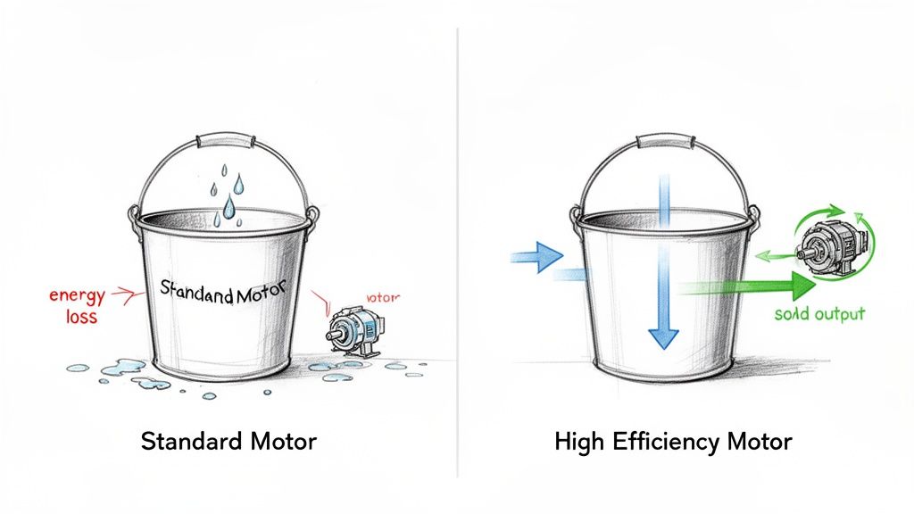
Think of a standard electric motor like a leaky bucket. You pour electricity in, but a good portion of it leaks out as wasted heat before it can do any real work. High-efficiency motors are the sealed bucket—they’re engineered to turn as much of that electricity as possible directly into the mechanical power your facility needs.
This guide isn't about a simple component swap. It's about a strategic shift in thinking that can drastically cut your operating costs and boost reliability across the board.
Why High-Efficiency Motors Are a Strategic Investment
In any industrial plant, whether it's manufacturing, food and beverage, or water treatment, electric motors are the workhorses. They're everywhere, running pumps, fans, conveyors, and compressors, and they are almost always one of the biggest line items on your utility bill. Even a small improvement in efficiency, when multiplied across dozens or hundreds of motors running 24/7, adds up to serious savings.
This is more than just an incremental upgrade. Moving to high-efficiency motors is a fundamental change in how plant engineers, procurement managers, and OEMs should approach equipment specs. It means looking past the initial price tag to see the far more important total cost of ownership.
The Real Cost of a "Cheaper" Motor
Believe it or not, the purchase price of an electric motor only accounts for about 2-5% of its total lifetime cost. The real expense—often over 95%—is the electricity it consumes over years of hard work.
A standard-efficiency motor is constantly wasting money by converting electricity into heat instead of torque. That excess heat doesn't just disappear; it actively works against you, causing premature wear on windings and bearings. This leads to higher maintenance bills and, worse, a greater risk of unplanned downtime.
High-efficiency models are designed to crush this problem. They use better materials, are built to tighter tolerances, and feature smarter designs that minimize those electrical and mechanical losses. This delivers a few key wins:
Lower Energy Bills: This is the most obvious benefit. The savings often pay for the motor itself in under two years.
Better Reliability: These motors run cooler. A cooler motor means longer life for its insulation and bearings, which translates to less maintenance and fewer breakdowns.
Cooler Operations: A motor that isn't throwing off as much heat can also reduce the load on your facility's HVAC systems, creating secondary savings.
Building a Foundation for Modern Systems
Specifying high-efficiency electric motors is about more than just saving on a single machine; it's about building a smarter, more resilient operational foundation. Industry standards like NEMA Premium® and the IEC's IE classes give you a clear benchmark for performance, so you know you're getting the efficiency you paid for.
For any industrial operation, the logic is simple: every kilowatt-hour saved drops directly to the bottom line. Upgrading to a premium-efficiency motor is one of the most reliable and predictable ways to boost profitability while making your facility more robust.
The full potential of these motors is really unlocked when they're paired with an expertly integrated UL control system. A well-designed control panel ensures the motor runs in its sweet spot, protecting your investment and maximizing performance from day one. This guide will walk you through how to make it happen.
Decoding Motor Efficiency Ratings: NEMA and IE Classes
Trying to make sense of electric motor specs can feel like learning a new language. You're hit with terms like NEMA Premium, IE3, and IE4, but what do those labels actually mean for your bottom line?
Think of these ratings as a simple ladder. Each step up represents a serious drop in wasted energy—the electricity that just turns into heat instead of productive work. For anyone responsible for specifying motors, climbing this ladder isn't just about efficiency; it's about making a smarter, more profitable choice for the long haul.
NEMA: The North American Standard
Here in North America, the National Electrical Manufacturers Association (NEMA) is the authority. For a long time, their NEMA Premium® efficiency rating has been the gold standard for high-performance motors. When you see that label, you know you're getting a motor that’s guaranteed to meet a high bar for performance, losing less electricity as useless heat.
The NEMA Premium standard was a huge step forward, pushing the entire industry away from old, energy-guzzling designs. Choosing a NEMA Premium motor sends a clear message: you're prioritizing long-term operational savings over a slightly lower price tag upfront.
IEC: The Global Efficiency Language
On the world stage, the International Electrotechnical Commission (IEC) provides a similar framework with its International Efficiency (IE) classes. This system creates a universal language for motor performance, which makes it much easier to compare products from different manufacturers around the globe.
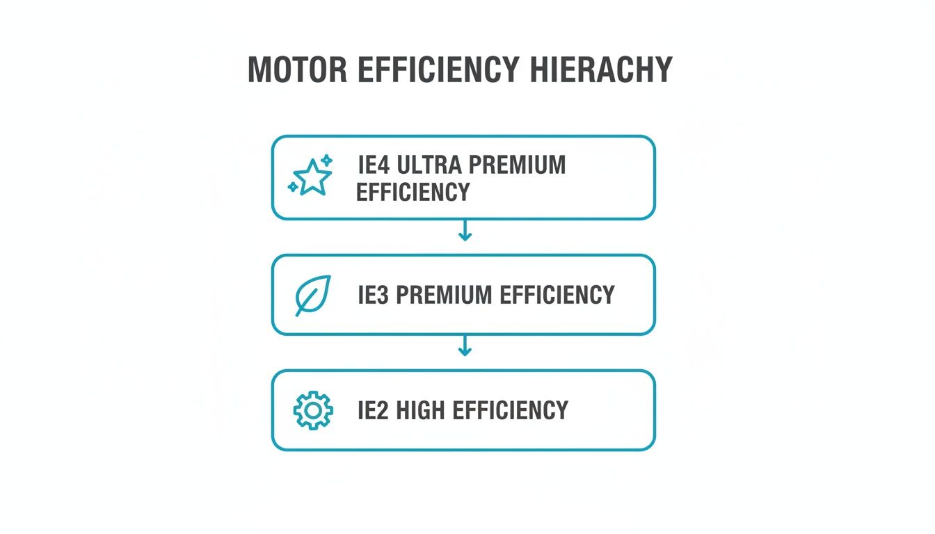
The IE classes are a simple, logical progression:
IE1 (Standard Efficiency): The old baseline. You won't see these in new installations in most places anymore.
IE2 (High Efficiency): A good step up, but in many markets, you'll need to pair these with a VFD for new applications.
IE3 (Premium Efficiency): This is today's global standard and the direct counterpart to NEMA Premium. IE3 is where the energy savings really start to stack up.
IE4 (Super Premium Efficiency): This class pushes the envelope of motor design, offering even bigger energy savings. These are perfect for continuous-duty jobs where even a small efficiency gain delivers a massive return over the motor's life.
The momentum is undeniable. In the US industrial sector alone, upgrading motor systems could save an incredible 37-79 billion kWh every year. While many facilities say that 47-77% of their new motor purchases are premium-efficiency, there's still a huge opportunity left on the table. You can dive deeper into these Department of Energy findings on motor market assessments.
Why IE3 Is The New Normal
For almost any new project, specifying an IE3 or NEMA Premium motor isn't just a good idea—it's often the law. Regulations across the United States and Europe have made these efficiency levels a mandatory minimum for most new motors sold. This has completely reshaped the market, making high-efficiency the default choice, not the exception.
Making IE3 your facility's baseline doesn't just keep you compliant; it future-proofs your entire operation. As energy costs climb and regulations inevitably get tighter, standardizing on premium-efficiency motors shields you from future headaches and locks in savings for years to come.
Understanding how these global standards relate is key to making the right choice, no matter where your project is. This quick table breaks down the common equivalents.
NEMA Premium vs IEC Efficiency Classes At A Glance
IEC Class
Efficiency Level
Common NEMA Equivalent
Typical Application Use Case
IE2
High
EPAct / High Efficiency
Often used in existing systems or where regulations allow; may require VFD pairing for new installations.
IE3
Premium
NEMA Premium®
The standard for new pumps, fans, compressors, and conveyors in continuous or frequent-duty cycles.
IE4
Super Premium
NEMA Super Premium (guideline)
Best for 24/7 applications like large-scale HVAC systems or critical process machinery where lifecycle costs are paramount.
IE5
Ultra Premium
(No direct equivalent)
Emerging technology for specialized applications demanding the absolute peak of motor performance and energy reduction.
Ultimately, whether the label says NEMA Premium or IE3, the goal is the same: to ensure you're installing a motor that works smarter, not harder, delivering performance you can count on while cutting down your energy bill.
Seeing Past the Sticker Price: The True Cost and ROI of High-Efficiency Motors
The initial price tag on a new electric motor is probably one of the most misleading numbers on any industrial budget. It feels like the main event, but in reality, it’s just the cost of admission. The real cost—the one that chips away at your bottom line for a decade or more—is the electricity that motor will guzzle down, day in and day out.
When you look at the total lifecycle cost, that upfront purchase price typically accounts for just 2-5% of the money you'll spend. The other 95%? Almost all of it is energy. This one simple fact should completely reframe how you approach motor procurement. That "cheaper" standard-efficiency motor isn't a smart buy; it's a long-term financial drain disguised as a deal.
Let's break down how to see past the initial price to calculate the Total Cost of Ownership (TCO) and Return on Investment (ROI). Once you see the numbers, the case for high-efficiency motors becomes impossible to ignore.
Breaking Down the Lifecycle Cost
Total Cost of Ownership isn't just a corporate buzzword; it's the complete financial story of a piece of equipment. For a motor, the formula is refreshingly simple and shines a bright light on where the money really goes.
Initial Purchase Price: This is the upfront capital outlay. It's what everyone focuses on, but it's the smallest piece of the pie.
Installation & Commissioning: The labor and materials needed to get the motor bolted down and wired up.
Energy Consumption: This is the heavyweight champion of motor expenses, dictated by runtime, load, and, most importantly, efficiency.
Maintenance & Repairs: All the scheduled servicing, replacement parts, and the painful costs of unplanned downtime.
Disposal Costs: The expense of decommissioning the motor when it finally reaches the end of its operational life.
Out of all these, energy consumption absolutely dwarfs everything else. Every single percentage point you gain in efficiency is a direct, recurring reduction in this massive operating expense.
Each step up this ladder, like moving from a workhorse IE2 motor to a modern IE3 premium model, locks in a significant and guaranteed cut in energy waste.
A Real-World ROI Calculation
Let's get practical. Say you're looking at a 100 HP motor running 8,000 hours a year where you pay $0.10/kWh for electricity. A standard motor with 82.5% efficiency will burn through a staggering $723,394 in electricity over a 10-year life.
Now, what happens if you upgrade to a 94.5% efficient IE3 premium motor? The energy bill for that same period drops to $615,534. That’s a $107,860 savings on a single motor. This isn't just theory; it's the kind of math we do every day for plant managers and EPC firms, pairing the right motors with VFDs and UL control panels to deliver rapid paybacks.
This kind of saving isn't a rounding error—it's a massive operational win hiding in plain sight. When you can walk into a budget meeting with this kind of detailed financial analysis, the decision to invest in efficiency becomes incredibly straightforward. To dig even deeper into the numbers, check out our guide on how to calculate electric motor efficiency. And while it's from a different industry, this pricing guide and cost breakdown shows just how powerful a detailed financial analysis can be for any major investment.
The Key Takeaway: The premium you pay for a high-efficiency motor isn't a cost. It’s an investment. In almost any industrial application, that investment pays for itself with energy savings, often in less than two years.
The Rebate Accelerator: Getting Paid to Upgrade
The financial picture gets even brighter. Many utility companies offer substantial rebates for businesses that install energy-efficient equipment, and high-efficiency motors are often at the top of their list. These programs can directly chip away at the initial purchase price, sometimes covering the entire cost difference between a standard and a premium model.
Why would they pay you to use less of their product? It’s simple economics. It is far cheaper for a utility to help you save a kilowatt of power than it is for them to build the infrastructure to generate a new one.
It’s a true win-win:
Your Facility: You get a top-tier, reliable motor with a drastically shorter payback period.
The Utility: They reduce demand on the grid and hit their energy conservation targets.
By taking advantage of these programs, you can turn a multi-year ROI into a matter of months, making the upgrade a no-brainer for even the most risk-averse financial teams.
How to Properly Size a Motor for Peak Performance
In any industrial plant, one of the most common and expensive mistakes we see is motor oversizing. It usually comes from a good place—a well-intentioned but misguided effort to build in a "safety factor." What you end up with is a powerful motor running at a tiny fraction of its capacity. It's like using a sledgehammer to crack a nut. Sure, the job gets done, but it’s incredibly wasteful.
When an oversized motor runs at a partial load, you force it way outside its peak efficiency zone. This mistake completely wipes out the benefits of choosing electric motors high efficiency to begin with, burning through the very energy you paid a premium to save. Real-world performance comes from a perfect match between the motor’s capability and what the application actually demands.
The Problem with Partial Loads
Electric motors are designed to hit their efficiency sweet spot when operating between 75% and 100% of their rated load. When the actual workload dips below this range, especially under 50%, the motor's efficiency doesn't just dip—it plummets. This isn't a small drop; the energy losses are significant, leading directly to higher electricity bills and a lot more heat.
That excess heat isn't just wasted energy; it's a direct threat to the motor itself. It cooks the windings and bearings, accelerating their breakdown, which means more maintenance and a higher risk of unexpected failure. Oversizing a motor doesn't make it more reliable; in many cases, it does the exact opposite.
A properly sized motor isn't just about efficiency; it's a cornerstone of operational reliability. By matching the motor to the true workload, you ensure it operates in its sweet spot, maximizing both energy savings and its service life.
Mastering the Art of Load Analysis
To sidestep the oversizing trap, you have to get past the theoretical maximums and focus on the actual load profile of your application. This means doing a bit of homework to understand the system's needs throughout its entire operational cycle.
A solid load analysis involves a few key steps:
Measure the Actual Load: Don't guess. Use a power analyzer to measure the real power consumption of the existing motor under its normal working conditions. This gives you hard data on what the machine truly needs.
Account for Load Variations: Is the load constant, or does it bounce around? Applications like pumps and fans often have variable demands, which require a totally different sizing strategy than a constant-torque conveyor belt.
Calculate Required Torque: For many machines, knowing the torque requirements is critical for picking the right motor. If this is new territory, a good torque calculation for motor guide can give you a strong foundation to build on.
Consider Starting Torque: Some equipment, like heavily loaded conveyors or positive displacement pumps, needs a big kick to get going. Make sure the motor you choose can handle that initial demand without being way too big for its normal running state.
Using VFDs for Variable Load Applications
For any system where the demand fluctuates, a Variable Frequency Drive (VFD) is an absolute game-changer. Think of a VFD as a smart throttle for your motor, perfectly matching its speed and power output to the load's real-time needs. This lets you size the motor for the peak load while still running efficiently during those times of lower demand.
While many manufacturer datasheets boast efficiencies over 95%, real-world conditions often tell a different story. One study that analyzed performance data from 48 different electric motors found the average maximum efficiency was just 77.64%, with the best performer hitting 97.61%. This shows just how much factors like load variations impact what you see in the field, making systems like VFDs even more critical.
By pairing a correctly sized motor with a VFD, you can achieve peak performance across the entire operating range, delivering maximum savings and extending the life of your equipment.
Tying It All Together: Motors, Drives, and UL Control Panels
A high-performance motor on its own is like a world-class sprinter without a starting block—it has all the potential in the world but lacks the system to launch it into action. The true power of high-efficiency electric motors is only unlocked when you pair them with intelligent control systems. This is where premium motors, Variable Frequency Drives (VFDs), and custom UL-listed control panels come together to create a powerful, synergistic system that delivers peak performance and safety.
This isn't just a matter of connecting a few wires; it's about building a unified "nervous system" for your equipment. Think of it this way: the motor is the muscle, the VFD is the brain, and the UL control panel is the protective backbone ensuring everything operates safely and reliably. For industrial OEMs and system integrators, mastering this integration is the key to building turnkey solutions that win in the real world.
The VFD: Your Key to Dynamic Efficiency
A VFD is the ultimate efficiency multiplier for your motor. Instead of just running full-blast all the time, a VFD fine-tunes the motor's speed to perfectly match the real-time needs of the application. It’s like a smart gas pedal for your motor, giving it precisely the right amount of power at any given moment—and not a drop more.
This is a game-changer for any application with variable loads, like pumps, fans, and blowers. Old-school methods relied on inefficient mechanical dampers or valves to restrict flow. A VFD simply slows the motor down, a change that can lead to dramatic energy savings, often exceeding 50%.
But the benefits go way beyond the electric bill. VFDs also bring a level of control that protects your entire mechanical system. Their "soft-start" capability gently ramps the motor up to speed, which drastically cuts down on the mechanical shock and electrical inrush current that hammers equipment during a traditional startup. That simple function extends the life of everything from belts and gears to the motor itself.
The UL Control Panel: Your Guarantee of Safety and Compliance
If the motor and VFD are the heart of your system, the UL control panel is the armor that protects it. A professionally engineered, UL-listed control panel is so much more than a metal box with switches. It's a fully integrated system designed from the ground up for safety, reliability, and strict compliance with national electrical codes.
A UL 508A certification isn't just a sticker. It's an independent guarantee that the entire assembly has been designed and built to the highest safety standards. It confirms every component, from circuit breakers to wiring, has been properly selected, installed, and tested to work together safely.
This third-party verification is absolutely critical. It smooths the path for getting equipment signed off by local inspectors, gives your end-users confidence, and provides a clear line of defense against electrical hazards. Skipping this certification is a huge gamble that can lead to costly project delays, failed inspections, and serious safety liabilities.
Bringing It All Together for Peak Performance
The synergy between these three components creates a system that is far greater than the sum of its parts. A high-efficiency motor provides the efficient foundation, the VFD optimizes its performance in real time, and the UL control panel ensures it all operates safely and within code.
For industrial OEMs and system integrators, this integrated approach delivers some powerful advantages:
Single-Source Responsibility: Partnering with someone who can engineer and build the complete motor and control package simplifies your procurement and guarantees everything is compatible from day one.
Faster Commissioning: A pre-engineered, pre-tested UL panel arrives on-site ready to go. That slashes your installation and startup time.
Enhanced Reliability: When you know all the components are designed to work together, you drastically reduce the risk of integration headaches and premature failures down the road.
Ultimately, integrating high-efficiency electric motors with the right control system transforms them from standalone parts into a cohesive, high-performance asset. You can explore our expert insights to learn more about the benefits of variable speed AC motor control and how it can be applied to your specific needs.
Putting It All Together: Your High-Efficiency Motor Strategy
Alright, we’ve covered the why and the what. Now it's time to build a real-world action plan. The single most important takeaway from this guide should be this: thinking about high-efficiency electric motors as a simple expense is a mistake. It’s a strategic investment, one that pays for itself surprisingly quickly through lower energy bills and fewer breakdowns.
Let's move from theory to the shop floor. The whole point is to create a simple, repeatable process for your team to follow for procurement and project management. When you have a solid strategy in place, every single motor purchase—whether it’s a planned upgrade or a middle-of-the-night replacement—becomes a calculated move toward a more profitable operation.
Your Action Plan Checklist
A winning motor strategy isn't about reinventing the wheel every time. It’s about consistency and making decisions based on data, not just habit. Instead of treating each purchase like a one-off emergency, use a standardized checklist to make sure you’re squeezing every drop of value out of high-efficiency technology.
Here are the essential steps to build right into your process:
Audit Your Existing Motor Fleet: Start by walking the floor. Pinpoint those old, power-hungry motors, the ones that fail too often, or the ones that are clearly too big for the job. Your biggest and fastest ROI will come from replacing oversized or continuously running motors first.
Specify the Right Efficiency Class: Draw a line in the sand. From now on, IE3 (NEMA Premium) is the absolute minimum standard for any new or replacement motor in your facility. For those critical 24/7 applications? It's time to run the numbers on an IE4 motor and see how much more you could be saving.
Conduct a Lifecycle Cost Analysis (LCA): Stop looking at just the sticker price. It's the least important number. Grab a calculator and figure out the ten-year energy cost of that new motor. This simple step builds an undeniable business case for the premium efficiency option every single time.
Verify Proper Sizing and Application: Don't just replace like-for-like. Make sure the new motor is sized for the actual load it will see, not just what the nameplate on the old clunker says. If the load changes, it’s a perfect candidate for a VFD.
Standardize and Consolidate: Talk to your supplier and start standardizing on a few specific motor brands and models. This is a huge, often-overlooked win. It simplifies maintenance, shrinks your spare parts inventory, and makes ordering a breeze.
Adopting a formal motor strategy is the difference between reactive maintenance and proactive management. It ensures that every dollar spent on motor assets is an investment in long-term efficiency, reliability, and profitability.
At the end of the day, a winning strategy is about more than just buying better parts; it’s about finding the right partners. Working with experts who can actually audit your facility, specify the right motor and control package, and deliver a reliable, code-compliant UL-listed system is the fastest way to guarantee you see the best possible return on your investment.
Got Questions About High-Efficiency Motors? We've Got Answers.
Even when you've got a solid plan, a few questions always pop up before pulling the trigger on a motor upgrade. Here are some of the most common ones we hear from plant engineers, maintenance managers, and procurement teams, along with some straight-to-the-point answers.
Do High-Efficiency Motors Need Special Maintenance?
Nope. In fact, it's often the opposite. High-efficiency motors follow the same maintenance playbook you're already using for standard motors—think regular lubrication, vibration checks, and keeping them clean.
But here’s the kicker: because they run cooler, the stress on critical components like bearings and winding insulation is significantly lower. This often means a high-efficiency motor will actually need less attention over its long life, which chips away at your total cost of ownership.
The real key is consistency. A proper installation and a proactive maintenance schedule will unlock the full reliability of any motor, efficient or not.
There's a myth that premium motors are somehow more delicate. The reality is their better build quality and cooler operating temps make them tougher and more forgiving in demanding environments, often leading to greater reliability and longer service intervals.
Can I Just Swap a Standard Motor for a High-Efficiency One?
For the most part, yes. Manufacturers design high-efficiency motors to be "drop-in" replacements. They almost always share the same NEMA frame sizes, mounting dimensions, and shaft heights, making the physical swap-out a breeze.
Still, there are two small details you'll want to double-check:
Full Load Amps (FLA): Premium motors are more efficient, so they draw a little less current. That’s a good thing, but it means you might need to adjust your existing motor protection and overloads to match the new, lower rating.
Speed (RPM): Due to lower "slip," high-efficiency motors tend to run a few RPM faster than their standard-efficiency cousins. This difference is tiny and won't matter for most pumps, fans, and conveyors, but if you're working with a precision timing application, it's something to be aware of.
Are These Motors Okay to Use with a VFD?
Absolutely, but you have to use the right kind. You need to specify a motor that is explicitly inverter-duty rated. These motors have a beefed-up insulation system designed to handle the unique voltage spikes created by a Variable Frequency Drive (VFD).
If you run a standard, non-inverter-duty motor on a VFD, you're asking for trouble. It can cause the insulation to break down prematurely, leading to a fried motor and unexpected downtime. Always look for "inverter-duty," "inverter-rated," or a similar label on the motor's nameplate to protect your investment.
What's the Real Difference Between IE3 and NEMA Premium?
They're essentially two different names for the same level of high efficiency. IE3 is the classification used by the International Electrotechnical Commission (IEC), which is common globally. NEMA Premium is the standard used here in North America.
Think of it as saying the same thing in a different language. When you're sourcing motors in the U.S., specifying NEMA Premium ensures you’re getting a motor that meets the globally recognized IE3-equivalent benchmark. It keeps procurement simple and guarantees you're installing a motor built for modern performance and energy savings.
Ready to build a motor strategy that delivers a guaranteed ROI? The experts at E & I Sales provide premium motors, custom UL control packages, and turnkey system integration to make sure your projects are efficient, reliable, and done right. Contact us today to start your upgrade.
Engineered maintenance services are all about getting ahead of the curve. It’s a smart, proactive strategy that blends deep engineering know-how with advanced data analysis to predict and stop equipment failures before they ever happen. This approach completely changes the game, moving maintenance from a reactive "break-fix" model to a strategic one that optimizes the entire lifecycle of your critical industrial assets, from electric motors to complex UL-listed control systems.
Beyond the Break-Fix Mentality
Think of a Formula 1 pit crew. They don't just wait for a tire to blow out. They use live telemetry to see engine stress in real-time and prevent a breakdown mid-race. That’s the exact mindset behind engineered maintenance services. It’s a conscious shift away from the old—and incredibly expensive—cycle of waiting for something to break and then scrambling to fix it.
Instead of seeing maintenance as just another line item on the budget, this approach turns it into a genuine strategic advantage. It weaves fundamental engineering principles into the day-to-day upkeep of your machinery, directly boosting the reliability, safety, and efficiency of your most important assets. For plant managers and original equipment manufacturers (OEMs), this is a powerful way to drive operational excellence.
From Reactive to Proactive
The traditional way of doing things is purely reactive. A motor burns out, a control panel shorts, and suddenly, your entire production line grinds to a halt. What follows is a frantic scramble to diagnose the issue, find the right parts, and get a technician on-site—all while the costs of downtime pile up. In fact, unplanned downtime costs industrial manufacturers an estimated $50 billion every single year.
Engineered maintenance flips that script. It starts by asking a much better question: "How can we engineer failure right out of the system?" This forward-thinking strategy is built on a few key pillars:
Data-Driven Decisions: Forget rigid schedules or waiting for an alarm to go off. This is about using real-time data from sensors and diagnostic tools to get a true picture of equipment health.
Root Cause Analysis: When a problem does pop up, the goal isn't just a quick patch. It’s about digging deep to understand the underlying engineering cause so it never happens again.
Lifecycle Optimization: We're looking at the entire lifespan of an asset—from its first day of commissioning to its final replacement—to make sure you get the absolute maximum value out of it.
System-Level Thinking: This isn't just about one component. It’s about understanding how your motors, drives, and control systems all interact, letting you spot potential points of failure within the bigger picture.
By focusing on proactive, data-informed strategies, engineered maintenance services don't just fix problems—they systematically prevent them, turning upkeep into a predictable and value-driven activity.
This strategic pivot creates a clear path toward rock-solid reliability. By using real engineering expertise to make sense of complex data, your facility can move past simple preventive checklists and start tackling the fundamental reasons equipment fails in the first place. It’s all about creating an operation that is more resilient, predictable, and ultimately, more profitable.
So, what does an engineered maintenance services program actually look like on the ground, beyond the high-level strategy? Think of it less as a single service and more as a sophisticated diagnostic toolkit for your entire operation.
It’s a suite of specific, data-driven techniques and technologies all working in concert to give you an unprecedented look into the health of your most critical assets. Each component is designed to detect the subtle, almost invisible signs of wear and tear long before they spiral into catastrophic failures. The goal is to catch problems at their absolute earliest stage when they are cheapest and easiest to fix.
Predictive Diagnostics: Your Early Warning System
At the heart of any modern maintenance program, you'll find predictive diagnostics. This isn't just about following a schedule; it's about using advanced tools to listen for the earliest whispers of trouble, turning abstract data into real, actionable intelligence. It's like a doctor using an EKG to spot a heart issue before any outward symptoms ever appear.
This proactive stance is only possible thanks to a few key technologies:
Vibration Analysis: Every rotating machine, whether it's a motor, pump, or fan, has a unique vibration signature when it's running smoothly. We use specialized equipment to measure this signature and detect tiny changes that signal developing problems like bearing wear, shaft misalignment, or imbalance.
Thermal Imaging: Overheating is one of the most common and destructive signs of electrical and mechanical stress. Using infrared thermography, our technicians create a visual map of heat, allowing them to spot a faulty connection in a UL-listed control panel or an overworked motor long before it burns out.
This is what it means to be proactive—connecting real-world data with a clear strategy to stop failures before they ever start.
Specialized Motor and Control Panel Maintenance
While predictive tools are vital, they're only half the battle. They need to be paired with deep, hands-on expertise, especially when it comes to high-value assets like industrial motors and custom control panels. Maintenance for these complex systems goes way beyond a simple checklist.
For electric motors, this means targeted services like motor circuit analysis and advanced lubrication management. Just doing lubrication right can prevent over 50% of premature bearing failures. But an engineered approach takes it further by analyzing the lubricant itself for microscopic metal fragments that indicate internal wear.
Maintaining UL-listed control panels is even more critical because it directly impacts safety and compliance. A specialized program ensures every single component, from circuit breakers to variable frequency drives, is functioning exactly to specification. This isn't just about preventing downtime; it's about protecting your people and ensuring the entire system keeps its UL certification.
Let's take a look at the core services that make up a robust engineered maintenance program. The table below breaks down what each service does and where it's typically applied, giving you a clear picture of how these components fit together to protect your assets.
Key Services in an Engineered Maintenance Program
Service Component
Primary Objective
Typical Application
Vibration Analysis
Detect early-stage mechanical faults in rotating equipment.
Motors, pumps, fans, gearboxes, compressors
Thermal Imaging
Identify overheating in electrical and mechanical systems.
Control panels, circuit breakers, motor casings, bearings
Motor Circuit Analysis
Assess the electrical health of a motor from the controller.
AC/DC motors, generators
Lubricant Analysis
Analyze oil and grease for contaminants and wear particles.
Bearings, gearboxes, hydraulic systems
Commissioning
Verify new or repaired equipment meets performance standards.
New production lines, upgraded motor controls, custom panels
Each of these services provides a different piece of the puzzle. When combined, they give you a complete, 360-degree view of your equipment's health, allowing for truly intelligent and proactive maintenance decisions.
Why This Level of Expertise Is More Important Than Ever
Demand for these advanced services is surging as more industries finally recognize the crushing cost of unplanned downtime. It’s part of a massive market shift where businesses are investing heavily in technical expertise to stay competitive. In fact, the U.S. engineering services market hit USD 407.3 billion in 2024 and is projected to reach USD 581.0 billion by 2030.
That kind of growth points to a fundamental truth in modern industry: combining advanced diagnostic technology with deep engineering knowledge isn't a luxury anymore—it's a competitive necessity.
To get started organizing these efforts, you can see how it all fits into a broader plan with our guide on creating a preventive maintenance schedule template. By building a program around these core components, you can transform your maintenance department from a reactive cost center into a powerful driver of productivity and profit.
Calculating the ROI of Proactive Maintenance
Getting buy-in for engineered maintenance services means translating the technical wins into the language everyone understands: dollars and cents. Sure, things like vibration analysis and thermal imaging are impressive, but their real magic is measured in saved costs and boosted productivity. This is where calculating the return on investment (ROI) becomes your most convincing tool.
Think of engineered maintenance not as an expense, but as a strategic investment in your plant's profitability. The ROI calculation proves this by putting the cost of doing nothing—unplanned downtime—head-to-head against the cost of a smart, proactive program. For anyone in procurement or project engineering, this gives you a clear, data-driven case to make.
The True Cost of Unplanned Downtime
First things first: you need to figure out what an unexpected failure actually costs your business. It’s almost always way more than just the price of a replacement part. An equipment failure creates a domino effect of expenses that can ripple through your entire operation.
To get a real number, you have to add up a few key factors:
Lost Production: This one’s the biggie. How much revenue do you lose for every hour a line is down?
Labor Costs: Think about the wages for idle operators just standing around, plus the overtime you’ll pay your maintenance crew for the emergency fix.
Repair and Replacement: This covers the new parts—often at a premium for rush delivery—and any outside contractors you have to call in.
Secondary Damage: A catastrophic motor failure can easily take out other components with it, turning a small problem into a massive, expensive repair.
Add all that up, and you get a clear cost-per-hour of downtime for your most critical assets. That number is the bedrock of your entire ROI calculation.
Building a Hypothetical ROI Scenario
Let's walk through an example. Imagine a critical conveyor system in a manufacturing plant, all run by a large electric motor. The plant has done its homework and knows that every hour this conveyor is down costs them $20,000 in lost production and other expenses.
Over the last year, this conveyor failed out of the blue three times, leading to a total of 15 hours of downtime.
The Cost of Inaction: 15 hours of downtime × $20,000 per hour = $300,000 in lost revenue
Now, let's say the plant decides to invest $50,000 a year in an engineered maintenance services program for its critical motors. This program includes quarterly vibration and thermal scans, which catch two of the three potential failures before they can happen. The team addresses these issues during scheduled maintenance, so there’s zero unplanned downtime from them.
One minor, unpredictable failure still slips through, but because the system is being monitored, they catch it much faster. It only leads to 3 hours of downtime instead of the usual 5.
Calculating the Financial Return
With a proactive program in place, the plant’s financial picture looks a whole lot better. The annual cost of downtime plummets to just $60,000 (3 hours × $20,000). To find the net savings, we just subtract the new downtime cost and the program's cost from the original loss.
Net Savings: $300,000 (original loss) – $60,000 (new downtime cost) – $50,000 (program cost) = $190,000
Now for the ROI. The formula is simple:
(Net Savings / Program Cost) × 100 = ROI
In our scenario, that looks like this: ($190,000 / $50,000) × 100 = 380% ROI
That’s a powerful number. It means that for every dollar the company put into the maintenance program, it got $3.80 back in saved revenue. This completely changes the conversation from "How much does it cost?" to "How much will it save us?" To dig deeper, check out our guide on the benefits of predictive maintenance for manufacturing.
This shift toward financial returns and reliability is why the maintenance services market is booming. The global market, which covers everything from electric motor controls to automation, was valued at USD 81.86 billion in 2025 and is projected to hit USD 122.09 billion by 2029. That's a compound annual growth rate of 10.5%, all driven by the need for smarter upkeep and sustainable tech.
Defining Success with KPIs and Service Agreements
Any good partnership for engineered maintenance services has to be built on a foundation of clarity and trust. You can't just cross your fingers and hope for the best. To make the relationship work, you need to agree on what "success" actually looks like from the very beginning. This is where Key Performance Indicators (KPIs) and a well-defined Service Level Agreement (SLA) come into play.
Think of KPIs as the scoreboard for your entire maintenance program. They’re the hard numbers that tell you if your strategy is paying off. Vague goals like “improving reliability” won't cut it; you need real data to measure progress and prove the value of your investment.
Key Performance Indicators That Matter
When you're trying to gauge the impact of an engineered maintenance program, you want to focus on metrics that truly reflect the health of your equipment and the efficiency of your operations. Instead of drowning in a sea of data points, it's better to zero in on a handful of KPIs that tell a compelling story.
Here are a few of the most critical ones we see making a real difference:
Mean Time Between Failures (MTBF): This is the average time your equipment runs without a hitch between breakdowns. If your MTBF is trending upward, it’s a fantastic sign that your proactive maintenance is working, preventing failures before they happen.
Overall Equipment Effectiveness (OEE): OEE is the gold standard for measuring just how productive your manufacturing time really is. It combines availability (uptime), performance (speed), and quality (defects) into one powerful metric. A rising OEE score means your maintenance efforts are directly contributing to your bottom line.
Maintenance Cost per Unit: This KPI connects your maintenance spend directly to your output. If this number starts to drop, it’s proof that you're getting more efficient and your maintenance program is delivering a stronger return on investment.
These aren't just numbers on a spreadsheet. They turn maintenance from a reactive, "gut-feel" chore into a data-driven strategy, giving you the proof you need to show real improvements in uptime and profitability.
Table: Reactive Maintenance vs Engineered Maintenance
It’s one thing to talk about proactive maintenance, but seeing the difference side-by-side really drives the point home. The old "if it ain't broke, don't fix it" model is a recipe for surprise downtime and spiraling costs. An engineered approach, on the other hand, is about getting ahead of the curve.
Here's a quick comparison:
Aspect
Reactive Maintenance (Break-Fix)
Engineered Maintenance (Predictive)
Philosophy
"Wait for it to fail, then fix it."
"Predict and prevent failure before it happens."
Downtime
Unplanned and often extensive.
Minimal and scheduled.
Costs
High, unpredictable emergency repair costs.
Lower, predictable, and budgeted.
Asset Lifespan
Shortened due to repeated failures.
Extended through proactive care.
Safety
Higher risk from unexpected equipment failure.
Improved safety through well-maintained equipment.
The takeaway is clear: Engineered maintenance is a strategic investment in reliability, while reactive maintenance is a constant, costly firefighting exercise.
Crafting a Strong Service Level Agreement
Once you’ve nailed down your KPIs, the next step is to cement them into a formal Service Level Agreement (SLA). An SLA is so much more than a contract; it’s a shared playbook that outlines expectations, responsibilities, and performance goals. It ensures you and your service provider are always on the same page.
A well-structured SLA is the bedrock of a transparent and accountable partnership. It puts expectations in writing, defines performance targets, and clarifies what happens if those commitments aren't met, protecting everyone involved.
A solid SLA has to be specific and realistic. It should clearly define the scope of services and the exact performance targets your provider is committing to. For any engineered maintenance program, your SLA should always include:
Guaranteed Response Times: How fast will a technician be on-site? This should be clearly defined for different levels of urgency, from a routine check to a critical failure.
Uptime Commitments: Set a clear target for equipment availability, like 99.5% uptime for your most critical assets. This ties your provider’s performance directly to your operational stability.
KPI Reporting Standards: Agree on how often you'll get performance reports and what they'll look like. This should include monthly dashboards tracking trends in MTBF, OEE, and your other key metrics.
Scheduled Maintenance Windows: A clear, agreed-upon schedule for all preventive and predictive work ensures tasks get done on time without causing unnecessary production delays.
By setting these benchmarks before you even start, you're building a framework for success. It transforms your maintenance program from a simple list of tasks into a strategic initiative with measurable outcomes that deliver genuine business value.
How to Choose the Right Maintenance Partner
Picking a partner for engineered maintenance services is a huge decision, one that goes way beyond signing a simple vendor contract. You're not just hiring a crew to fix broken equipment; you're handing them the keys to the operational heart of your entire facility. The right partner acts like an extension of your own team, bringing in deep engineering know-how to proactively keep your most critical assets humming.
Get this choice wrong, and you're staring down the barrel of recurring failures, surprise downtime, and serious safety risks. But a truly great partner can flip that script, turning maintenance from a reactive, money-pit of a department into a predictable, value-adding part of your operation. That requires a vetting process that cuts through the sales fluff and zeroes in on what they can actually do and what they've already done.
Vetting Technical Expertise and Field Experience
First things first, you have to dig into their technical chops. Any potential partner needs to prove they have a profound understanding of your specific equipment and the environment it runs in. This is absolutely critical when you’re dealing with specialized gear like UL-listed control panels or intricate motor control centers, where safety and compliance aren't just suggestions—they're the law.
Start asking sharp questions about their real-world, hands-on experience. A qualified team should be able to walk you through their process without stumbling.
Diagnostic Tooling: Do they own and use modern diagnostic tools like thermal imagers and vibration analyzers, or are they just going to farm that work out to someone else? Having this tech in-house usually means a stronger commitment and quicker response when things go sideways.
Engineering Resources: Are there actual professional engineers on staff who can dig into a root cause failure analysis? You want a team that recommends system improvements, not just one that knows how to swap out a part.
System Integration Knowledge: How well do they play with your existing automation and control architecture? Their ability to plug in without causing chaos is a massive factor. We talk more about what separates the good from the great in our guide on choosing an industrial automation system integrator.
A partner’s value isn't just in the fancy tools they bring to the job. It's in the engineering brainpower that can actually interpret the data. The best in the business can look at a subtle vibration reading, connect it to a specific mechanical fault, and then engineer a solution that makes sure it never happens again.
Assessing Safety Protocols and Proven Track Record
Beyond the technical skills, you need to see a rock-solid commitment to safety and a documented history of getting the job done right. A strong safety culture is about protecting your people and your plant. A solid track record gives you the peace of mind that they can actually deliver on what they promise.
When you’re checking out potential providers, really dig into their operational history and safety standards. This is how you separate the seasoned pros from the rest of the pack.
Critical Evaluation Checklist
Use this checklist to keep your conversations focused and make it easier to compare your options:
Safety Record: Ask to see their formal safety program and hard numbers, like their Experience Modification Rate (EMR). A low EMR is a clear sign they take safety seriously and perform consistently.
Case Studies and References: Don't just take their word for it. Ask for real-world case studies that are relevant to your industry and equipment. More importantly, insist on talking to a few of their current clients who are facing the same challenges you are.
Reporting and Communication: How are you going to know what’s going on? A professional partner will provide detailed reports that are easy to understand and clearly connect their maintenance work to your business goals.
Training and Certifications: What kind of training are their techs getting? Look for certifications that matter, like NFPA 70E for electrical safety, credentials in predictive tech, and any OEM-specific training.
At the end of the day, choosing the right partner for engineered maintenance is about finding a team that's on the same page as you. You need a group with the technical depth, the proven experience, and an unwavering focus on safety to not just fix your assets, but to actively make them more reliable and high-performing for the long haul.
Engineered Maintenance in Action
All the theory and technical talk is great, but let's be honest—what really matters is how this stuff works in the real world. Seeing engineered maintenance services solve messy, high-stakes problems is where the true value clicks. It’s how the concept goes from a line item on a budget to a genuine game-changer for your entire operation.
This isn't just a niche service, either. The industrial maintenance market, which covers specialized work on things like motor control centers, was a USD 57.6 billion industry in 2024. It's on track to hit a staggering USD 108.24 billion by 2035.
What’s fueling that growth? A massive shift toward predictive maintenance. In fact, a whopping 91% of companies using it report they’re seeing fewer breakdowns and faster repair times. You can dig into more of these industrial maintenance market trends if you're curious.
Eliminating Delays for a Packaging OEM
Picture a food packaging OEM. Their entire business model hinges on hitting tight shipping deadlines, day in and day out. The problem was, their main conveyor system kept shutting down at random, creating massive production bottlenecks. Every failure put shipments on hold and soured relationships with their biggest clients.
They finally put a predictive maintenance plan in place, zeroing in on the conveyor's motor controls. Technicians started running regular vibration analysis, and it wasn't long before they spotted the early signs of wear on a critical bearing in one of the primary drive motors.
Instead of waiting for a catastrophic failure, they swapped out the bearing during a planned maintenance window. The result? Zero unplanned downtime for the next fiscal year. No more late shipments, and client confidence was fully restored.
This is a perfect example of how engineered maintenance directly protects your revenue. It shifted their entire mindset from reactive firefighting to a smart, proactive defense against costly downtime.
Boosting Compliance at a Water Treatment Facility
Here's another great example from a municipal water treatment facility. They were stuck with old, clunky control panels that were not only sucking down way too much power but also making it nearly impossible to keep up with changing regulatory standards.
The fix was a complete upgrade to custom-engineered, UL-listed control panels. This move didn't just solve one problem—it delivered two huge wins. The new system came with energy-efficient variable frequency drives (VFDs) built-in.
The outcome was a night-and-day difference:
Compliance Assured: That UL listing gave them documented proof that their systems met the latest industry requirements, making audits a breeze.
Energy Costs Slashed: The new VFDs adjusted motor speeds based on real-time demand, cutting the plant's energy bill by over 20%.
These stories drive home a key point. Engineered maintenance is so much more than just preventing breakdowns. It’s a powerful strategy that tackles complex business challenges, from logistics and customer satisfaction to regulatory compliance and cost control.
Your Questions, Answered
Making the switch to a smarter maintenance strategy always brings up a few questions. Let's tackle some of the most common ones we hear from plant managers and facility operators who are considering engineered maintenance services.
Is This Just for Massive Industrial Plants?
Not at all. While the big players definitely see huge returns, the core ideas of engineered maintenance scale beautifully to fit operations of any size. It’s all about applying the effort where it has the most impact.
For a small or mid-sized facility, the first step is usually a criticality analysis. A good partner will sit down with you to pinpoint that handful of machines where an unexpected shutdown would really hurt. By aiming predictive tools and engineering know-how at just those critical systems, you can get a serious ROI without a massive initial spend.
How Long Until We See Results?
This isn't a year-long waiting game. The rollout is almost always done in phases, specifically so you can start seeing value right away.
The initial discovery phase—auditing assets, setting up sensors, and getting baseline data—usually takes just a few weeks. After that, we can launch a pilot program on your most critical equipment within the first couple of months. This gives you early wins and proves the concept. A full, facility-wide implementation might stretch over six to twelve months, but the program is designed to pay for itself long before it’s fully complete.
The whole point is to generate tangible value, and fast. A phased approach lets you knock out the highest-risk problems first, delivering a clear ROI that builds a rock-solid case for expanding the program.
Isn't This Just a Fancy Name for Predictive Maintenance?
That's a common misconception, but the difference is pretty significant. The easiest way to think about it is that Predictive Maintenance (PdM) is one of the tools in the toolbox, while Engineered Maintenance is the entire strategic game plan.
Predictive Maintenance (PdM): This is all about using technology like vibration analysis and thermal imaging to forecast a failure. It answers the question, "When is this motor bearing likely to give out?"
Engineered Maintenance Services: This is the bigger picture. It uses PdM but adds a crucial layer of deep-dive problem-solving. We’re talking root cause failure analysis, system design improvements, and managing the asset's entire lifecycle. It doesn't just predict the failure; it works to engineer it out of the system for good by asking, "Why did the bearing fail in the first place, and what can we redesign to make sure it never happens again?"
In short, predictive maintenance is a tactic. Engineered maintenance is the complete strategy for winning the war against downtime.
Ready to turn your maintenance department from a cost center into a competitive advantage? The team at E & I Sales brings the deep engineering expertise and advanced diagnostic tools you need to keep your most critical systems running flawlessly. Start building a more reliable operation today.
Ever seen a device that's both a light switch and a bodyguard for your industrial equipment? That's the simplest way to think about a fuse disconnector switch. It's a single, rugged component that marries the manual on-off control of a switch with the automatic overcurrent protection of a fuse, letting you safely kill power for maintenance while shielding your machinery from electrical damage.
The Two-in-One Job of a Fuse Disconnector Switch
In any plant or on any factory floor, keeping people safe and machines running are the two pillars of a successful operation. The fuse disconnector switch is a cornerstone for both, handling two critical jobs at once. It’s not just a switch, and it’s certainly more than a simple fuse holder—it's an integrated safety device that solves some of the biggest challenges in industrial control.
This dual-function design is exactly why it's so dominant in the market. In fact, fused models accounted for a staggering 67.79% revenue share in 2023, within a global disconnect switch market valued at USD 15.02 billion. Why the preference? Because it’s a proven way to prevent catastrophic failures in industries where every minute of downtime costs a fortune. You can see more market data on disconnect switches over at Grand View Research.
To help clarify how it pulls off this double duty, let's break down its two primary functions.
Function
Mechanism
Primary Goal
Key Benefit
Circuit Protection
Fuse element melts during overcurrent or short circuit, breaking the circuit.
Protect downstream equipment from electrical damage.
Prevents costly equipment failure and extends asset life.
Manual Isolation
User operates a handle to physically separate electrical contacts (create an air gap).
Ensure a zero-energy state for safe maintenance and servicing.
Enables compliance with Lockout/Tagout (LOTO) procedures.
In essence, the fuse provides the automatic protection, while the switch provides the manual control needed for human safety.
The Gatekeeper for Electrical Safety
First and foremost, the device is your local point of isolation. Picture a maintenance tech needing to work on a critical conveyor motor. Without a clear and verifiable way to de-energize that motor right where the work is happening, the job becomes incredibly dangerous. The disconnector’s handle provides that positive break, physically separating the contacts and creating a visible air gap in the circuit.
This is the bedrock of any Lockout/Tagout (LOTO) safety program. The handle is almost always lockable, ensuring the machine can't be accidentally powered back on while someone's hands are in it. It’s the definitive gatekeeper, guaranteeing a zero-energy state so your team can work safely. You can get a deeper dive into the basics of what a disconnect switch does in our detailed guide.
The Bodyguard for Valuable Equipment
At the same time, the device stands guard over your valuable assets. Housed inside are fuses, each one carefully sized for the specific circuit it’s protecting. If a short circuit or a dangerous overload condition occurs, the fuse element is designed to melt and break the circuit—all within milliseconds.
This rapid, sacrificial action stops destructive electrical energy dead in its tracks, long before it can fry expensive motors, VFDs, or PLCs. It’s the frontline defense that often makes the difference between swapping out a simple fuse and facing a multi-thousand-dollar repair bill.
By combining these two roles into one compact unit, the fuse disconnector switch gives you a cost-effective and highly reliable solution for both control and protection.
How a Fuse Disconnector Switch Actually Works
To really get a feel for what these devices do, you have to picture what’s happening inside the box, both when you throw the handle and when an electrical fault suddenly erupts. It’s less like a single component and more like a well-drilled team, with each part playing a role in control and protection.
At its core, the whole assembly is a clever marriage of a simple manual switch and a set of sacrificial fuses, all bundled into one neat package. You’ve got the handle on the outside, a switching mechanism on the inside, carriers to hold the fuses, and the all-important electrical contacts. When you pull that handle, you’re physically moving a linkage that forces the contacts apart, creating an air gap that cuts the power. Simple, reliable, and effective.
The Two Modes: Manual Control and Automatic Rescue
Every fuse disconnector switch lives a double life, operating in two very different but equally vital modes: manual isolation and automatic protection. Nailing down this dual personality is the key to understanding why they're so essential in a control panel.
Here's the breakdown of how each one works:
Manual Isolation: This is the hands-on part. An operator grabs the handle and moves it from ON to OFF. That simple physical action drives a cam or linkage inside, pulling the movable contacts away from the stationary ones. This creates a visible, verifiable air gap that completely de-energizes everything downstream, making it safe for a technician to get to work.
Automatic Overcurrent Protection: This is the "hero" mode. When a short circuit or a massive overload hits, a huge wave of current surges through the fuse. The little filament inside is designed to vaporize in milliseconds under that load, instantly breaking the circuit. The fuse sacrifices itself to save expensive motors, drives, and other critical gear from getting fried.
This flowchart really brings the process to life, showing how the switch responds to an electrical event.
You can see the straightforward logic: a fault occurs, the device protects the circuit, and then it provides a safe point of isolation.
A Growing Role in Modern Systems
The beautiful simplicity and rock-solid reliability of this mechanism are why we're seeing it in more places than ever. The global market for these panel-mounted switches was already valued at USD 2.8 billion in 2024. Projections show it climbing to USD 5.1 billion by 2034, growing at a steady 5.9% CAGR. What's driving this? A boom in construction and an unending need for industrial control panels that are, above all, safe. You can dig deeper into the market dynamics from this industry analysis.
The core principle is simple but powerful: the switch provides the deliberate, manual control needed for human safety, while the fuses offer the instantaneous, automatic protection required for equipment integrity.
In the end, it doesn't matter if it's an operator pulling the handle or a fault triggering the fuse—the result is the same. A safe, de-energized circuit. This dependable, two-pronged approach is what makes the fuse disconnector switch a non-negotiable part of any modern industrial electrical system. It's all about protecting both people and machinery.
How to Select the Right Fuse Disconnector Switch
Picking a fuse disconnector switch isn't like grabbing a generic part off the shelf. Get it wrong, and you're not just looking at a minor hiccup—you're risking damaged equipment, code violations, and serious hazards for anyone working on the panel. The right choice is the one that keeps your system protected and safe to service.
Making the right call means digging into the unique demands of your application. A switch destined for a tight motor control panel has a completely different set of requirements than one acting as the main disconnect for a massive piece of machinery. Your selection process needs to be a methodical, step-by-step evaluation of the electrical environment and what you're trying to protect.
Key Ratings You Cannot Ignore
Think of electrical ratings as the switch's DNA. If they don't match your system, it’s a recipe for disaster. Three ratings, in particular, are absolutely critical.
Voltage Rating (AC/DC): This is non-negotiable. The switch's voltage rating must be equal to or, even better, greater than your system voltage. Using an underrated switch is asking for insulation failure and dangerous arcing.
Continuous Current (Amperage): The switch has to handle the normal, everyday operating current of your circuit without breaking a sweat—or overheating. For motors, this is sized based on the Full Load Amps (FLA), usually with a safety factor baked in per code.
Short Circuit Current Rating (SCCR): This is arguably the most important safety rating of them all. The SCCR tells you the absolute maximum fault current the switch can safely interrupt without catastrophic failure. It must be higher than the available fault current where it’s installed.
The SCCR isn't a suggestion; it's a hard-and-fast safety metric. An improperly rated fuse disconnector can literally explode if it sees a fault current beyond its capacity, creating a life-threatening arc flash and destroying equipment.
The relentless push for safer industrial environments has made these devices essential. In fact, the global market for In-Line Fuse Switch Disconnectors hit a staggering US$4,612 million in 2024, a number driven by strict safety standards that demand reliable overcurrent protection and isolation. This focus on safety is paying off, helping to reduce downtime by up to 30% in critical operations by enabling faster, safer repairs. You can dig deeper into these trends over at Valuates Reports.
Sizing for a Motor Control Application
Let's walk through a real-world scenario that every panel builder and plant engineer has faced: sizing a disconnect for a 10 HP, 480V three-phase motor.
Find the Motor FLA: First, check the motor nameplate. A standard 10 HP motor at 480V will have a Full Load Amperage (FLA) right around 14 amps.
Size the Switch Amperage: The NEC tells us the disconnect needs to be rated for at least 115% of the motor's FLA. So, that’s 14A x 1.15 = 16.1A. You can't buy a 16.1A switch, so you step up to the next standard size, which is a 30A model.
Choose the Fuse Class and Rating: Here's where the nuance comes in. To handle the motor's inrush current on startup without blowing, you need a time-delay fuse. A Class J or RK5 fuse is perfect for this. The fuse amperage is sized higher than the FLA—often up to 175% or more, depending on the motor's code and design.
Verify the SCCR: Last but certainly not least, you have to check the available fault current in the panel. Let's say it's 18,000A. You'll need a switch and fuse combination with an SCCR of at least 25,000A (the next common rating up) to be safe.
Fuse Class Comparison for Motor Circuits
Choosing the right fuse class is just as important as sizing the switch. The fuse determines how the device responds to overloads and short circuits. For motors, you need something that can handle the initial startup surge but act instantly on a dead short.
Fuse Class
Key Characteristic
Typical SCCR
Best For
Class J
Fast-acting, current-limiting, compact size. Excellent for space-sensitive applications.
200,000A
High-performance motor protection where SCCR and physical space are critical.
Class RK5
Time-delay, current-limiting, dual-element design. Handles motor inrush well.
200,000A
General-purpose motor circuits. A great balance of performance and cost.
Class CC
Time-delay, compact, "midget" fuse footprint.
200,000A
Smaller control circuits and fractional horsepower motors. Not for larger loads.
Class T
Very fast-acting, extremely current-limiting, very compact.
200,000A
Protecting sensitive solid-state components like VFDs; less common for standalone motor disconnects.
By walking through this logical process—evaluating the ratings, understanding the load, picking the right fuse, and verifying the safety specs—you can specify a fuse disconnector switch that delivers both bulletproof protection and uncompromising safety.
Best Practices for Installation and Wiring
Getting the installation and wiring right on a fuse disconnector switch is about more than just making the lights come on. It’s about building a safe, reliable, and compliant system. A sloppy install is a ticking time bomb—it can lead to overheating, equipment failure, and serious hazards, especially inside a UL 508A control panel where every component has to pull its weight.
Think of it this way: the care you take here is the foundation of your entire electrical system. Do it right, and you've built something that will stand the test of time.
Mounting and Mechanical Setup
First things first, you have to physically secure the switch. The right method really depends on your panel's layout and the specific model you're working with.
DIN Rail Mounting: For smaller switches inside a control panel, this is the way to go. It's fast, usually tool-free, and makes it a breeze to move things around during assembly.
Panel (or Door) Mounting: Bigger, beefier switches are typically mounted straight onto the back panel or the enclosure door. This gives them a solid base and makes it easy to add a through-the-door operator handle.
That through-the-door handle is a non-negotiable for operator safety. It lets someone kill the power before they even think about opening the panel door, which is a massive step in preventing arc flash incidents. Make sure this handle is lockable to meet Lockout/Tagout (LOTO) standards.
Wire Termination and Connections
How you land your wires is just as critical as where you mount the switch. You’d be surprised how many electrical failures and fires come down to nothing more than a bad connection. Always double-check you're connecting incoming power to the line side and outgoing power to the load side. Getting that backwards can create a seriously dangerous situation.
When you're doing any of this work, having a solid permit to work system in place is essential. It's a structured way to manage hazardous jobs and ensure everyone stays safe by verifying that equipment is properly de-energized.
Pro Tip: Don't just guess on the tightness of your connections. Use a calibrated torque wrench. Manufacturers provide specific torque values for a reason. Over-tightening can strip or damage the terminal, while under-tightening creates a high-resistance spot that will do nothing but generate heat.
Finally, give the switch some breathing room. Both the NEC and UL standards require specific clearances around components. This isn't just for show—it prevents arcing and allows heat to dissipate properly. Jamming components together is a code violation and makes any future maintenance a nightmare.
Follow these practices, and you'll end up with a clean, safe, and inspection-ready panel. If you’re just starting your panel build, our guide to industrial control panel design has a lot more tips to get you going.
Navigating Safety Standards and Code Compliance
A fuse disconnector switch isn't just another part in a control panel; it's a critical link in the safety chain. Getting bogged down in the alphabet soup of safety standards can be frustrating, but understanding the why behind them is what really matters. These rules, created by organizations like UL, NFPA, and OSHA, exist for one reason: to prevent catastrophic electrical failures and keep people safe.
Think of it this way: compliance isn't about checking a box to pass an inspection. It’s about building systems that are fundamentally reliable. When a maintenance tech needs to service a piece of machinery, they have to be absolutely certain that throwing the disconnect handle creates a true zero-energy state. Their life depends on it.
The Why Behind the Rules
The standards that apply to a fuse disconnector switch aren't just arbitrary rules. They’re the hard-won lessons from decades of real-world incidents, each designed to address a specific piece of the safety puzzle.
UL (Underwriters Laboratories): UL is all about the component's integrity. UL 98 specifically covers enclosed and dead-front switches, making sure they can handle the mechanical stress and electrical load of their job. Then you have UL 508A, the standard for industrial control panels, which dictates how that switch must be integrated into a larger, safe assembly.
NFPA (National Fire Protection Association): Most people know NFPA 70 as the National Electrical Code (NEC). This is the playbook for installation. It tells you exactly where disconnects need to be, how to size them, and what clearances are required to prevent fires and shock hazards.
OSHA (Occupational Safety and Health Administration): OSHA’s focus is squarely on the worker. Their regulations mandate Lockout/Tagout (LOTO) procedures, which are impossible without a lockable disconnect handle. This ensures a machine can't be accidentally turned on while someone is working on it.
At the end of the day, these standards work together to create a predictable, safe environment. A UL-listed switch, installed according to the NEC, and used as part of an OSHA-compliant LOTO program, forms an unbreakable chain of protection for both people and equipment.
SCCR and the Mandate for Safety
One of the most important—and often misunderstood—safety ratings on an industrial panel is its Short Circuit Current Rating (SCCR). This number tells you the maximum fault current the entire panel can handle without exploding or catching fire. The fuse disconnector switch is your first line of defense and is absolutely essential for achieving a high panel SCCR.
The fuses inside the switch have an incredibly high interrupting capacity, often 200,000A. This allows them to instantly protect all the downstream components—like VFDs or PLCs—that have much lower individual SCCR ratings. This makes the fused disconnect a foundational building block for any UL 508A compliant panel that is truly safe by design.
Keeping Your Switch Healthy: Maintenance and Troubleshooting
Even the toughest fuse disconnector switch is not a "set it and forget it" device. To keep them reliable and safe for the long haul, a little proactive care goes a long way. For any plant engineer or maintenance pro, getting ahead of problems is always better than reacting to a failure that causes unexpected downtime or, worse, a safety incident.
Think of it like this: regular maintenance is the key to catching small issues before they snowball into catastrophic failures. A few simple visual and mechanical checks can tell you everything you need to know about the health of your switch.
The Go-To Preventive Maintenance Checklist
A simple, repeatable inspection is your best line of defense. Over months and years, machine vibration can work connections loose, and environmental factors like dust and humidity can take their toll. Building these steps into your routine PM schedule is non-negotiable.
Torque It Down: Connections are notorious for loosening up. Use a calibrated torque wrench to make sure every line and load terminal screw is tightened to the manufacturer’s spec. A loose connection is just a hot spot waiting to happen.
Work the Handle: With the power off, of course, cycle the handle a few times. It should feel smooth and solid, not stiff or sloppy. Any binding or excessive force is a red flag.
Look for Hot Spots: Your eyes are one of your best tools. Scan for any signs of discoloration or charring on the wires, terminals, or the switch body itself. That’s a dead giveaway of overheating from a bad connection or an overload.
Check the Fuses: Make sure the right fuses are in there. Verify they are the correct size, class, and amp rating for the circuit. Also, check that they're sitting snug and secure in the carriers.
Think of this as a quick physical for a critical piece of your safety system. Spending a few minutes on these checks can dramatically extend the life of the switch and keep your entire system safer.
The Right Way to Replace a Blown Fuse
Sooner or later, a fuse is going to do its job and blow to protect your equipment. When it does, replacing it has to be done by the book, with an absolute focus on safety. There are no shortcuts here.
Kill the Power & Lock It Out: The first step is always to throw the switch handle to the OFF position. Immediately follow that by applying your facility's Lockout/Tagout (LOTO) procedure to the handle. This ensures no one can accidentally flip it back on while you're working.
Verify It's Dead: Trust, but verify. Use a properly rated multimeter to test for voltage on both the line and load sides of the switch. Always test your meter on a known live source before and after you test the switch to prove your meter is working.
Swap the Fuse: Only after you’ve confirmed a zero-energy state should you open the fuse door or pull out the carrier. Replace the blown fuse with an exact match—same class, same voltage, and same amperage.
Power Up Safely: Once the new fuse is in, remove your lock and tag, close the panel door, and only then should you move the handle back to the ON position.
A Few Common Questions From the Field
When you're out there designing panels or walking a plant floor, the same questions about fused disconnects tend to pop up. Let's clear up a few of the most common ones we hear from engineers and technicians.
Fused vs. Non-Fused Disconnects: What’s the Real Difference?
Think of a non-fused disconnect as a simple light switch for your equipment—its only job is to provide a clear, visible break in the power for service. It’s purely for isolation and offers zero defense if something goes wrong electrically.
A fuse disconnector switch, on the other hand, is the whole package. It does that same critical isolation job and integrates overcurrent protection with fuses. It’s a single, compact device that protects your circuit from both dangerous short circuits and damaging overloads.
Can I Use One as a Motor Starter?
Absolutely not. A fuse disconnector switch is built for safety and protection, not for the constant, day-in-day-out cycling of starting and stopping a motor. That kind of repetitive action will destroy it.
For actually running a motor, you need a dedicated motor starter, like a contactor and overload relay combo. They’re designed for that specific, high-endurance task.
It boils down to this: a motor starter is for operation, while a fused disconnect is for protection and isolation. Mixing up their roles is just asking for equipment failure and creating a genuinely unsafe situation.
How Do I Pick the Right SCCR?
This is a big one. The Short Circuit Current Rating (SCCR) you need is all about the "worst-case scenario." You have to figure out the maximum available fault current at the exact spot you're installing the disconnect.
Your fuse disconnector switch and the fuses you put in it must have a combined SCCR that is equal to or, even better, greater than that number. This guarantees it can handle a massive fault without exploding. Getting this calculation right is a non-negotiable part of designing a safe, compliant panel that meets UL 508A and NEC standards.
For robust, reliable UL-listed control solutions that incorporate the right fuse disconnector switch from the start, you can trust the experts at E & I Sales. Find out more at https://eandisales.com.
At its core, a disconnect switch is a straightforward, manually operated device designed for one critical purpose: to completely and visibly cut off a circuit from its power source. Think of it as an electrical safety switch. Its entire job is to create a physical "air gap," a clear, undeniable break in the circuit that guarantees electricity cannot flow past it. This makes it an absolute necessity for safe maintenance, repairs, or emergency shutdowns.
The Core Function of a Disconnect Switch
The best way to understand a disconnect switch is to think of it as the main water valve for your house.
When a plumber needs to fix a leaky pipe, they don't just turn off the faucet under the sink. They go straight to the main shutoff valve, closing it to ensure not a single drop of water can reach their work area. A disconnect switch provides that same level of absolute certainty for electricity.
This function isn't just about convenience; it's a cornerstone of electrical safety on the job. The ability to physically lock the switch in the "off" position is the foundation of the Occupational Safety and Health Administration's (OSHA) lockout/tagout (LOTO) procedures. This protocol is what stands between a technician and a machine that could accidentally be re-energized while they're working on it.
Why Visual Isolation Matters
You'll almost always find a disconnect switch installed "within sight" of the equipment it protects, and that’s by design. Unlike a circuit breaker that might be hidden away inside a panel down the hall, the disconnect switch gives a technician an immediate, visual confirmation that the circuit is dead.
That physical separation of contacts is the ultimate safeguard against electrical shock. There's no ambiguity.
A disconnect switch is a critical safety device in electrical systems, designed to physically isolate power circuits during maintenance, emergencies, or repairs, preventing accidents and ensuring worker safety in industrial settings.
Let's quickly summarize the key points in a table.
Disconnect Switch at a Glance
Key Aspect
Description
Primary Function
To safely and visibly isolate a circuit from its power source.
Mechanism
Creates a physical "air gap" in the circuit, preventing electrical flow.
Core Benefit
Ensures worker safety during maintenance and repairs.
Key Application
A critical component of Lockout/Tagout (LOTO) safety procedures.
Typical Installation
Placed "in-sight" of the equipment it controls for visual verification.
This at-a-glance view highlights just how fundamental these devices are in any robust electrical system.
Indispensable in Industrial Settings
For any company involved with motor control centers and UL-listed panels, disconnect switches are non-negotiable. They are essential for building reliable and code-compliant power distribution systems in manufacturing plants, automation projects, and beyond.
They act as the first line of defense, providing a secure way to isolate everything from a single motor to an entire production line. To get a better sense of what's driving the demand for these devices, you can explore detailed industry reports on the market.
A Look at the Main Types of Disconnect Switches
Not all disconnect switches are built the same; picking the right one is all about the job at hand. If you want to guarantee safety and keep your equipment running smoothly, you need to know the basic types. The biggest fork in the road is whether the switch provides its own overcurrent protection.
This single difference splits them into two major camps: fused and non-fused.
Fused vs. Non-Fused Switches
Think of a fused disconnect switch as a device wearing two hats. It’s both a manual "off" switch and a bodyguard for your circuit. Inside, it holds fuses that will blow and cut the power automatically if the current spikes to a dangerous level, saving an expensive motor or piece of machinery from getting fried.
A non-fused disconnect switch, on the other hand, has just one job: to isolate power. It's a purist. It offers zero overcurrent protection on its own, so it's only used in circuits where a circuit breaker or another device upstream is already handling that responsibility.
In a nutshell, fused switches give you isolation and overcurrent protection in one box, which is why they’re the go-to for motor circuits. Non-fused switches are strictly for cutting power, relying on a separate breaker to do the protecting.
It’s no surprise that fused switches dominate industrial settings. The low-voltage disconnect switch market, which is the backbone of motor control, was valued at $3.2 billion in 2023. The fused industrial slice of that pie is expected to hit $4.6 billion in 2024, which tells you just how critical that built-in protection is for machinery. You can dig into more of the numbers by reviewing these detailed industry findings.
Common Designs and Duty Ratings
Beyond just fused or non-fused, you’ll run into different designs built for specific loads and environments. They’re often separated by a "duty rating," which is just a fancy way of saying how tough they are.
Here are a few of the workhorses you’ll find out in the field:
Heavy-Duty Safety Switches These are the tanks of the disconnect world. Built for the grind of industrial applications, they’re designed for frequent use and can safely handle the high fault currents you see with big motor circuits and heavy machinery.
General-Duty Safety Switches Just like the name says, these are for lighter commercial or even residential jobs where the switch won't be thrown every day. They're a more budget-friendly option for things like service entrances or light-duty branch circuits where you don't need an industrial-grade build.
Rotary Disconnect Switches These guys are compact, versatile, and often found mounted right on a control panel or machine. A simple turn of the handle opens or closes the contacts. They are perfect for providing a local shut-off right where you need it, especially when space is tight. Panel builders love them for their small footprint and modular design.
Choosing between them means looking at what the circuit needs—everything from the electrical load and environmental conditions to the specific safety codes you have to follow.
How Disconnects Differ From Breakers and Contactors
It’s easy to get electrical components mixed up, especially when they all seem to "switch" power in one way or another. One of the most common points of confusion is the difference between a disconnect switch, a circuit breaker, and a contactor.
While they all sit in a circuit and control the flow of electricity, their core jobs are fundamentally different. Trying to substitute one for another is a recipe for an unsafe, unreliable system.
An Everyday Analogy: Your Home's Plumbing
Let's think about it in terms of the water flowing into your house. It's a surprisingly good parallel.
A contactor is like your kitchen faucet. You turn it on and off constantly throughout the day for a specific task. It’s designed for frequent, routine operation.
A circuit breaker is the emergency flood-stop valve in your basement. It sits there, doing nothing, until a pipe bursts. When it detects that sudden, dangerous rush of water, it snaps shut automatically to prevent a catastrophe.
The disconnect switch is the main water shutoff valve out by the street. A utility worker has to come out, turn it with a special tool, and lock it in the "off" position to guarantee no water can enter the house during major repairs. It’s a deliberate, manual safety action.
Unpacking the Core Functional Differences
The real distinction boils down to manual vs. automatic and safety vs. operational control.
A disconnect switch is a purely manual device, built for one thing: absolute safety isolation. When you throw that handle, you are physically creating a visible air gap in the circuit. There’s no ambiguity. It’s a guarantee that the circuit is de-energized so someone can safely perform maintenance. Its purpose is entirely focused on protecting people.
A circuit breaker, on the other hand, is an automatic safety device. It’s always on watch, monitoring the circuit for overloads and short circuits. The moment it detects a dangerous fault condition, it "trips" on its own to cut the power and protect the equipment from burning up. While you can often operate a breaker manually, its primary job is automatic protection.
Contactors play a completely different role. They are electrically operated switches, designed to be turned on and off frequently by a remote signal. A small control voltage energizes a coil, which pulls the main contacts closed to power up a motor or heater. They're all about operational convenience, not providing a positive, lockable point of isolation for safety.
The key takeaway is simple: Disconnects are for manual safety isolation, breakers are for automatic equipment protection, and contactors are for operational remote control. Each plays a distinct and non-interchangeable role.
To make this crystal clear, let's put them head-to-head.
Disconnect Switch vs Circuit Breaker vs Contactor
This table breaks down the essential differences at a glance, highlighting why you need the right component for the right job.
Component
Primary Function
Operation
Typical Application
Disconnect Switch
Safety Isolation
Manual (handle-operated)
De-energizing equipment for Lockout/Tagout (LOTO)
Circuit Breaker
Overcurrent Protection
Automatic (trips on fault)
Protecting circuits from overloads and short circuits
Contactor
Operational Control
Remote (electrically controlled)
Frequently starting and stopping motors
Understanding these distinct roles is the cornerstone of designing safe and compliant electrical systems. While a device like an ABB circuit breaker is a critical protective device, it simply cannot provide the same guaranteed, visible, and lockable isolation that a true disconnect switch offers. Using the right tool for the job isn't just a best practice—it's essential for a safe and reliable installation.
Where You'll Find Disconnect Switches in the Real World
Let's move from the textbook definitions to the factory floor. Disconnect switches aren't just a good idea; they're the non-negotiable heroes of nearly every industrial setting, crucial for both safety and keeping operations running smoothly.
Picture a massive manufacturing plant with conveyor belts, pumps, and mixers all humming along, powered by hundreds of electric motors. What happens when one motor on a critical production line needs a new bearing? You can't just shut down the entire facility. That would be a logistical and financial nightmare.
This is exactly where the disconnect switch proves its worth.
By placing a disconnect right at the motor, a technician can walk up, throw the handle, and completely isolate that single piece of equipment. This local cutoff point guarantees the machine is de-energized, making it safe for repairs while the rest of the plant keeps on producing.
Critical Roles Across the Plant
Once you know what to look for, you'll start seeing disconnect switches everywhere in a factory. Their presence is the sign of a thoughtfully designed and safe electrical system.
Here are some of the most common spots you'll find them:
Motor Control Centers (MCCs): These are the command centers for a plant's motors. Each motor "bucket" or unit inside the MCC gets its own disconnect, letting you safely work on one motor circuit without affecting the others.
Main Machinery Power: Every major piece of equipment—from a CNC mill to a giant hydraulic press—needs a main disconnect. This is the master "off" switch for the whole machine, absolutely essential for setup, maintenance, or hitting the brakes in an emergency.
HVAC and Pumping Systems: Think about the powerful systems running large commercial chillers, air handlers, and water pumps. Electrical code often requires a disconnect to be installed "within sight" of this equipment so a technician can kill the power right before putting their hands on it.
UL-Listed Control Panels: For a custom control panel to earn a UL 508A listing, it has to provide a way to cut all incoming power. A flange-mounted disconnect handle right on the enclosure door is the industry standard for meeting this requirement safely and effectively.
The market data really drives this point home. The industrial sector accounted for a staggering 43.71% of all disconnect switch sales in 2023. Why? Because industries like manufacturing and power generation rely on them to prevent downtime, which can easily cost millions. You can dig into the numbers in this disconnect switch market trends report.
At the end of the day, in any industrial environment, the disconnect switch is the physical barrier between high-voltage power and a human being. Its simple, tough design provides the clear, visible, and lockable power isolation that stops catastrophic accidents and costly shutdowns before they can happen.
Navigating Key Codes and Safety Standards
In the world of industrial power, a disconnect switch isn't just a good idea—it's a hard requirement, baked into the safety codes that govern everything we do. These standards are the rulebook, transforming a simple piece of hardware into a non-negotiable device that protects both people and equipment.
It all starts with the National Electrical Code (NEC). If you're dealing with motors, you live in Article 430. One of its most critical mandates is the "within sight" rule, which demands that a disconnect must be visible and located no more than 50 feet from the equipment it serves. This isn't arbitrary; it's a practical safeguard that prevents a technician from working on a machine while someone unknowingly re-energizes the circuit from down the hall.
Connecting Hardware to Human Safety
While the NEC lays out the rules for the hardware, the National Fire Protection Association (NFPA) focuses on keeping people safe around it.
That's where NFPA 70E, the Standard for Electrical Safety in the Workplace, comes in. This is the playbook for safe work practices, and it’s the reason we have procedures like Lockout/Tagout (LOTO). A disconnect switch is the linchpin of any LOTO procedure, providing that essential, lockable point of isolation that NFPA 70E requires before a single tool is lifted.
Think of it this way: The NEC tells you how and where to install the disconnect. NFPA 70E tells you why and how to use it to make sure everyone goes home safe.
The Role of UL Certification
For anyone building control panels, Underwriters Laboratories (UL) standards are gospel. UL provides that critical third-party stamp of approval, verifying that components and entire assemblies meet rigorous safety and performance benchmarks.
Two standards are absolutely essential here:
UL 98 (Enclosed and Dead-Front Switches): This is the standard for the disconnect switch itself. It gets put through its paces to ensure it can reliably interrupt current and handle nasty fault conditions without failing.
UL 508A (Industrial Control Panels): This one applies to the whole finished product—the control panel. To earn that coveted UL 508A listing, the panel must have a certified main disconnecting means. That makes a UL 98-rated switch a foundational building block for any compliant panel.
Picking the right disconnect switch goes way beyond just matching the voltage and amperage on the label. Get this choice right, and you’re setting your system up for safety, reliability, and code compliance. Get it wrong—say, by undersizing the switch or picking the wrong enclosure—and you're looking at premature failure, serious safety hazards, and downtime that'll hit your bottom line hard.
You have to look at the whole picture. It's like choosing tires for a truck. You wouldn’t slap standard highway tires on a rig that's heading off-road, right? The same logic applies here. A general-duty switch just won't survive in a harsh industrial environment that demands a heavy-duty model.
Your Essential Selection Checklist
Before you even think about purchasing a disconnect switch, run through this checklist. Nailing these details from the get-go will save you from massive headaches later.
Horsepower (HP) Rating: This is non-negotiable if the switch is for a motor. Motors pull a massive amount of current when they first start up, and the switch absolutely must be rated to handle that specific motor load.
Enclosure Type: The environment is everything. Is it a corrosive or washdown area? You'll need a NEMA 4X enclosure. Just a dusty indoor spot? A NEMA 12 might do the job just fine.
Fault Current Rating: The Short Circuit Current Rating (SCCR) has to be high enough to handle the worst-case scenario. It must safely withstand the maximum potential fault current at that point in the system, preventing a catastrophic explosion during a short circuit.
Fused vs. Non-Fused: Do you need the switch itself to provide overcurrent protection (fused)? Or is there already a breaker or fuse upstream handling that job (non-fused)?
Choosing the right disconnect switch is a foundational step in building a safe electrical system. Overlooking a detail like the enclosure type or fault current rating doesn’t just risk the switch; it risks the equipment it protects and the personnel who operate it.
Best Practices for Long-Term Maintenance
Once it's installed, a disconnect switch isn't a "set it and forget it" device. It needs regular attention to stay reliable and safe throughout its service life. Neglecting maintenance is a common—and dangerous—mistake. The good news is that proactive care is pretty simple.
A solid maintenance plan is your best tool. If you're looking for a great starting point, check out the principles for maintaining motor control centers, as many of them apply directly to the disconnects inside.
Here are the key tasks to stay on top of:
Regular Inspections: Do a visual walk-through. Look for tell-tale signs of overheating, like discolored terminals or melted insulation. Check for any hint of corrosion or moisture getting inside the enclosure.
Connection Tightness: Things loosen up over time thanks to vibration and the constant heating and cooling of electrical cycles. Get a torque wrench out periodically and make sure all terminal lugs are tightened to the manufacturer's specs.
Mechanical Operation: During a planned outage, throw the handle. Operate the switch a few times to make sure the mechanism moves freely. You don't want to find out it's seized up from years of inactivity during an emergency.
Answering Your Top Questions About Disconnect Switches
Even after getting the basics down, a few common questions always seem to pop up on the plant floor. Let's clear up a couple of the most frequent points of confusion to sharpen your understanding and help you make safer, smarter decisions.
Can a Circuit Breaker Double as a Disconnect Switch?
Sometimes, yes—but it's a qualified "yes." The National Electrical Code (NEC) does allow a circuit breaker to serve as a disconnecting means, provided it has the right ratings for the job. Critically, it must have a way to be locked out in the "off" position to comply with LOTO procedures.
Even so, many seasoned electricians and safety professionals will tell you they prefer a dedicated, standalone disconnect switch. Why? Because a traditional disconnect gives you that unmistakable visual confirmation—a physical air gap between the contacts—that the circuit is truly dead. It’s an extra layer of assurance you just can't argue with.
What Does the NEC Mean by "Within Sight of the Motor"?
This is a huge one, and it's a safety rule you can't afford to get wrong. The NEC defines "in sight from" as being visible and located no more than 50 feet away from the equipment it controls, like a motor.
The reasoning here is brilliantly simple and life-saving. It's designed to stop one person from accidentally re-energizing a machine while another technician, hidden from view, is working on it. This rule ensures the person performing the maintenance has direct, immediate control over the power source.
This decision tree gives you a great visual for the thought process behind choosing the right switch, walking through the key questions about the application, environment, and potential fault current.
As the guide shows, the single most important step is always matching the switch to its specific job.
Designing a safe, compliant, and rock-solid electrical system takes more than just buying components off a shelf—it demands a partner with deep experience in the field. At E & I Sales, we live and breathe this stuff, specializing in engineering UL-listed control panels and integrating motor controls built for the toughest industrial environments. Find out how our expertise can power your next project at https://eandisales.com.