When you're dealing with electrical equipment, the enclosure is your first and most important line of defense. A NEMA enclosure rating chart is the go-to tool for figuring out exactly what kind of protection you're getting. It cuts through the jargon and helps you match the right enclosure—like a NEMA 4X or NEMA 12—to the specific hazards of your plant floor or outdoor installation.
So, What Are NEMA Ratings, Exactly?
Think of the National Electrical Manufacturers Association (NEMA) rating system as the North American standard for grading how tough an electrical enclosure is. The whole point is to keep sensitive electronics and wiring shielded from whatever the environment throws at them, ensuring everything runs safely and reliably for the long haul.
This isn't just a simple "indoor" vs. "outdoor" label. The system gets incredibly specific. It spells out an enclosure's ability to stand up to everything from a clumsy operator accidentally touching a live part to fine, circulating dust, dripping water, or even the harsh bite of corrosive salt spray. Each rating number corresponds to a strict set of performance tests an enclosure has to pass.
Why This Matters on the Plant Floor
For any plant engineer or equipment packager, getting the NEMA rating right is non-negotiable. It's a decision that affects the lifespan of a motor control center, the precision of an automated packaging line, and the safety of your team. The wrong choice leads to fried components, unplanned downtime, and serious safety hazards.
The NEMA rating system has been around since the organization was founded way back in 1926, and it's more critical now than ever. In the U.S. manufacturing world, downtime from industrial automation costs a staggering $50 billion every single year. But here’s the kicker: simply choosing the correct NEMA-rated enclosure can cut equipment failure rates by as much as 40%. You can learn more about how these ratings impact day-to-day industrial control panel design.
This guide is built to be your definitive reference, breaking down each NEMA type so you can specify enclosures with total confidence.
Key Takeaway: Using a NEMA enclosure rating chart isn't just about ticking a box on a spec sheet. It's a strategic move to protect your investment, keep your people safe, and sidestep the massive financial hit that comes with equipment failure.
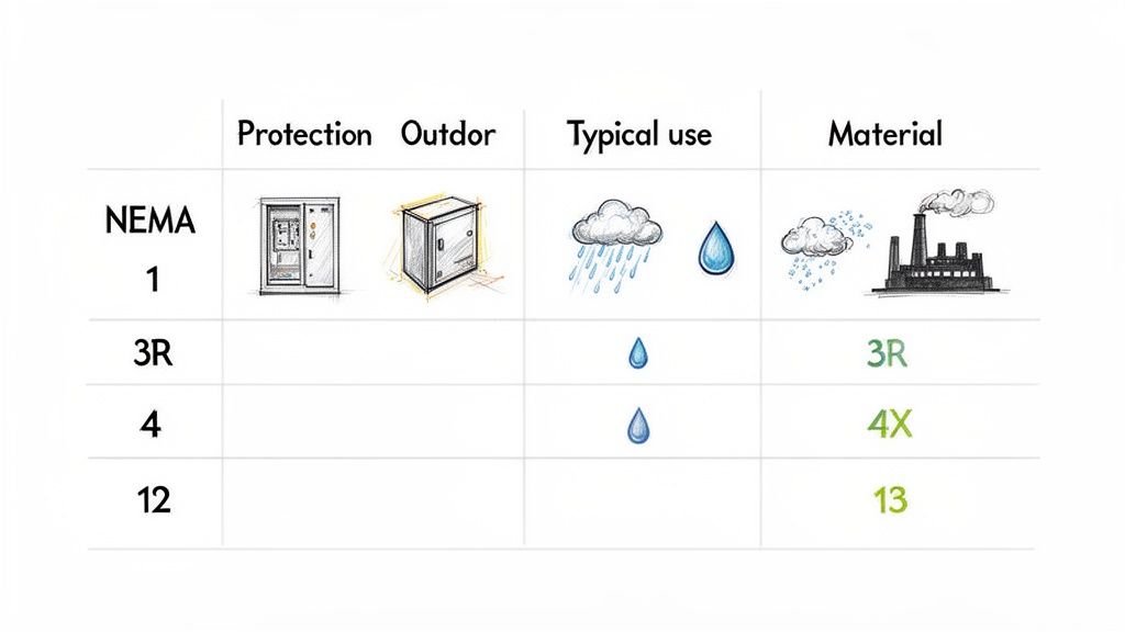
NEMA Enclosure Ratings Quick Reference Table
For a quick overview, this table breaks down the most common NEMA ratings. It’s a handy starting point for narrowing down your options before diving into the finer details.
Same as NEMA 12, plus spraying of oil and coolants
Indoor
CNC machines, presses, and other industrial machinery
This table is great for at-a-glance comparisons, but always refer to the detailed descriptions for each NEMA type to ensure your selection fully meets the demands of your specific application.
A Detailed Look at Common NEMA Enclosure Ratings
While a quick-reference NEMA chart is great for a high-level overview, you can't confidently spec the right enclosure without knowing what each rating really means on the plant floor. Let's move beyond the summary and dig into the specific protections, typical materials, and real-world applications for the most common non-hazardous NEMA ratings you’ll run into.
Each one of these ratings was designed to solve a very specific set of environmental problems, from basic indoor protection all the way up to withstanding corrosive washdowns. Let's break them down.
NEMA 1: The General-Purpose Indoor Standard
A NEMA 1 enclosure is your most basic option, designed strictly for indoor use in clean, dry spaces. Its main job is simple: keep fingers away from energized parts and stop falling dirt from getting inside.
Don't expect any protection from liquids. Not even a light drip. Think of it as a fundamental safety barrier, not an environmental shield.
Primary Protection: Guards against someone accidentally touching internal equipment and shields from falling solid debris.
Typical Materials: You'll almost always find these made from painted carbon steel because they're meant for non-corrosive environments.
Common Applications: Perfect for junction boxes, switch enclosures, and control panels tucked away in office spaces, clean control rooms, or protected utility closets where moisture and heavy dust are non-issues.
NEMA 3R: Outdoor Weather Resistance
When you need to mount equipment outside, NEMA 3R is often the go-to, cost-effective choice. This rating is built to handle falling rain, sleet, and snow, and it will prevent external ice from forming on the enclosure.
One of the key features of a NEMA 3R enclosure is its drainage holes. This design is smart because it prevents water and condensation from building up inside, but it also means the enclosure is not dust-tight. Windblown dust and other debris can, and will, find their way in.
Practical Scenario: A NEMA 3R enclosure is the perfect fit for an outdoor disconnect switch or a metering cabinet. It does a great job of shielding components from the rain, but since it's not sealed against dust, you wouldn't want to put a sensitive control panel in one if it's in a dusty part of the yard.
NEMA 4 and 4X: Washdown and Corrosion Protection
The NEMA 4 rating is a major leap in protection. It’s designed for both indoor and outdoor use and is completely sealed against windblown dust, rain, splashing water, and even high-pressure hose-downs. This makes it a true workhorse in any environment that needs frequent, heavy cleaning.
A NEMA 4X enclosure gives you everything a NEMA 4 does, but with one critical addition noted by the "X": corrosion resistance.
NEMA 4: Provides a dust-tight and water-tight seal that stands up to hose-directed water. It’s usually made from painted carbon steel.
NEMA 4X: Delivers the exact same dust and water protection but is built from corrosion-resistant materials like 304 or 316 stainless steel or even polycarbonate.
These are absolutely essential in places like food processing plants, wastewater treatment facilities, and marine applications. In these settings, chemical exposure or salt spray would chew through a standard painted steel box in no time. Upgrading to NEMA 4X isn't a luxury; it's a critical investment in keeping your equipment alive.
NEMA 12 and 13: Indoor Industrial Protection
Inside the factory, NEMA 12 enclosures are the standard. They're built to protect equipment from circulating dust, falling dirt, and dripping non-corrosive liquids. This rating is specifically made for factory floors where airborne particles from manufacturing are a constant headache.
They feature sealed doors and gaskets, but don't make the mistake of thinking you can hit them with a pressure washer—they are not designed for the kind of washdown a NEMA 4 can handle.
A NEMA 13 enclosure has all the protection of a NEMA 12 but adds a crucial defense against oil and non-corrosive coolants. You'll specify this rating for anything near machining, stamping, or other industrial processes where oils and lubricants are being sprayed or splashed. The gaskets in NEMA 13 enclosures are made from special materials that won't break down when exposed to these fluids.
Example Comparison
Feature
NEMA 12
NEMA 13
Environment
Indoor, industrial factory floors
Indoor, machine shops, metalworking facilities
Liquid Protection
Dripping non-corrosive liquids
Spraying oil and non-corrosive coolants
Primary Use Case
Protecting controls on packaging lines
Housing electronics on CNC machines or presses
Getting these distinctions right is vital. If you put a NEMA 12 enclosure on a CNC machine, the coolant will eventually destroy the gasket, leading to equipment failure. This is exactly why a detailed grasp of each rating is so important for any plant engineer.
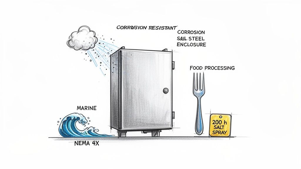
Breaking Down NEMA 4X for Corrosive Environments
When you're dealing with an industrial setting that's not just wet but also chemically harsh, a standard NEMA 4 enclosure just won't survive. This is precisely where the NEMA 4X rating comes in, setting the gold standard for protection in the toughest places you can imagine. That little 'X' in its name is the game-changer—it means serious corrosion resistance.
Sure, it gives you all the same great protection against hose-directed water, splashing, and windblown dust as a regular NEMA 4. The real difference, though, is in the materials. We're talking 304 or 316 stainless steel or beefy, high-grade polycarbonates that are built to take a beating from caustic chemicals, salt spray, and constant washdowns with aggressive cleaning agents.
Why That 'X' Matters So Much
That 'X' isn't just for show; it means the enclosure has been put through some serious corrosion-resistance testing. The most common trial by fire is the 200-hour salt spray test, which mimics years of exposure to highly corrosive marine or chemical environments. This is what separates a simple painted steel box from a truly battle-hardened NEMA 4X solution.
In industries where uptime is everything, picking the wrong enclosure can lead straight to disaster. In the U.S. alone, it's estimated that improper enclosure selection is behind 25% of electrical failures in corrosive settings. Switching to NEMA 4X can slash those incidents, saving companies millions in downtime and repairs. You can learn more about the critical role of NEMA-rated enclosures and how they protect your most valuable assets.
Bottom line: for certain sectors, NEMA 4X isn't just a good idea—it's an absolute must for equipment longevity and safety.
Where You'll See NEMA 4X in Action
The unique guts of a NEMA 4X enclosure make it the go-to choice in several key industrial environments. In each case, the rating's ability to fight off degradation is what keeps the enclosure—and the critical gear inside—alive and kicking.
Food and Beverage Processing: These plants are all about daily high-pressure washdowns with sanitizing chemicals. A NEMA 4X stainless steel enclosure is really the only way to go to stop rust and contamination, keeping everything in line with tough hygiene standards.
Wastewater Treatment Plants: Think corrosive gases like hydrogen sulfide and constant dampness. A NEMA 4X box is what stands between sensitive control systems and a swift death from chemical attacks and atmospheric corrosion.
Marine and Coastal Installations: Equipment on docks, ships, or anywhere near the ocean gets blasted with salt spray 24/7. Here, a NEMA 4X enclosure, usually made of 316 stainless steel for top-tier chloride resistance, is essential to stop rapid rust and failure.
Pharmaceutical and Chemical Plants: In these facilities, enclosures have to stand up to spills and vapors from a whole cocktail of aggressive chemicals. The solid construction of a NEMA 4X enclosure ensures control panels and junction boxes stay sealed and fully operational.
Expert Insight: Let's be clear: specifying a NEMA 4X UL-listed control panel isn't just following best practices; it's a smart business move. You're directly extending the life of your equipment, preventing incredibly expensive unplanned downtime, and making the plant safer for your team in places that would eat lesser-rated enclosures for lunch.
So, when you're looking at a NEMA enclosure rating chart, just remember that the 'X' in 4X signifies a whole other level of toughness. For any packager or plant engineer working in a corrosive environment, getting this distinction right is the key to building a system that's reliable and built to last.
NEMA Ratings vs. IP Equivalents: What's the Real Difference?
If you're specifying electrical enclosures, you're going to run into two main standards: NEMA and IP. Here in North America, a good NEMA enclosure rating chart is the bible. But for international projects, it's all about the Ingress Protection (IP) code. Knowing how the two relate is essential, but it’s definitely not a simple one-to-one conversion.
While both systems are designed to measure how well an enclosure protects what's inside, they don't use the same playbook. Their testing methods and what they cover are just different enough that you can't just swap one for the other. Trying to substitute a NEMA rating with what looks like its IP twin can cause some serious headaches, from failed inspections to fried equipment.
The Core Difference: NEMA vs. IP
The IP rating system is refreshingly straightforward. It focuses on just two things: how well it keeps out solid objects (that's the first digit) and how well it keeps out liquids (the second digit). The higher the number, the better the protection. Simple. For example, an IP67 rating tells you the box is completely sealed against dust (the "6") and can be dunked in water for a short time (the "7").
But the NEMA system goes deeper. Beyond just keeping stuff out, NEMA standards bake in tests for other real-world conditions you'll find on the plant floor. These extra layers of protection are exactly why a direct NEMA-to-IP conversion just doesn't work.
Corrosion Resistance: A rating like NEMA 4X has to prove it can stand up to corrosive agents, often by surviving a grueling 200-hour salt spray test. The IP system has no specific test for corrosion.
Oil and Coolant Protection: A NEMA 13 enclosure is built to handle the oils and coolants common in machine shops, something no standard IP rating even considers.
Dealing with Ice: Ever had an outdoor enclosure freeze over? NEMA ratings like 3R and 3S are specifically tested to ensure they work even when coated in ice, another blind spot for the IP system.
I've seen this mistake made a few times: someone assumes an IP68-rated enclosure is the same as a NEMA 6P. They both handle being submerged, sure. But the NEMA 6P rating also requires more intensive testing for corrosion and material aging, giving you an extra level of confidence the IP standard simply doesn't provide.
NEMA to IP Rating Conversion and Comparison Chart
So, how do you compare them? Think of this chart as a solid reference for finding the closest IP equivalent, not a direct translation. You always have to account for the extra protections that a NEMA rating brings to the table, especially when you're dealing with UL-listed applications here in North America.
NEMA Rating
Closest IP Equivalent
IP First Digit (Solids)
IP Second Digit (Liquids)
Key Differences and Additional NEMA Protections
1
IP20
2
0
NEMA 1 protects against falling dirt; IP20 protects against fingers/large objects.
3R
IP24
2
4
NEMA 3R specifically tests against rain, sleet, and external ice formation.
4 & 12
IP66
6
6
NEMA 4 is for hose-downs; NEMA 12 protects from dripping liquids and circulating dust.
4X
IP66
6
6
Crucial Difference: NEMA 4X adds mandatory corrosion resistance testing.
6
IP67
6
7
NEMA 6 protects during temporary submersion at a limited depth.
6P
IP68
6
8
NEMA 6P is for prolonged submersion and includes a corrosion resistance test.
13
IP65
6
5
NEMA 13 specifically adds protection against spraying oil and non-corrosive coolants.
At the end of the day, for any job in the U.S. or Canada, getting the NEMA rating right is non-negotiable. It's about safety, code compliance, and getting that all-important UL listing. While an IP rating is a useful point of comparison, the NEMA enclosure rating chart is, and will remain, the gold standard for any industrial application here.
How to Select the Right NEMA Enclosure
Knowing your way around a NEMA enclosure rating chart is one thing, but actually picking the right box for the job? That takes a deeper dive into your specific environment. It's less about just reading a chart and more about a consultative process—thinking through the entire lifecycle of the equipment, from the day it's installed to its long-term maintenance needs.
This approach is what ensures you land on a solution that hits the perfect balance of performance, cost, and rock-solid reliability.
A smart selection process always starts with the right questions. It’s not enough to know if an enclosure is going indoors or outdoors; you have to get granular about the challenges it will face day in and day out. A few minutes of thoughtful analysis upfront can prevent a world of hurt later, like over-specifying and blowing the budget, or worse, watching expensive equipment fail because its housing wasn't up to the task.
Key Questions to Guide Your Selection
Before you even think about settling on a NEMA rating, every plant engineer and packager needs to run through a quick mental checklist. Getting clear answers here will point you directly to the non-negotiables for your application.
What are the exact environmental hazards? Get specific. Is it just dripping water (NEMA 12), or are we talking high-pressure hose-downs (NEMA 4)? Is corrosive salt spray in the air (NEMA 4X)? You need to account for every potential threat, from fine dust and fibers to oil and chemical coolants.
What's going inside the box? Think about the heat your components will generate. Power-hungry gear like VFDs can turn an enclosure into an oven, which might mean you need a larger box, or even one with active cooling, to keep things from frying. This decision impacts both size and material.
How often do you need to get inside? Consider your maintenance crew. How frequently will they need to access the components? Enclosures with hinged doors, easy-to-use latches, or even clear windows can make a massive difference in maintenance time and operator safety.
Are there specific material requirements? A NEMA 4X rating requires corrosion resistance, but other factors come into play. Do you need lightweight aluminum? High-impact polycarbonate? Or is budget-friendly carbon steel good enough? The material has to match the environment and the project budget.
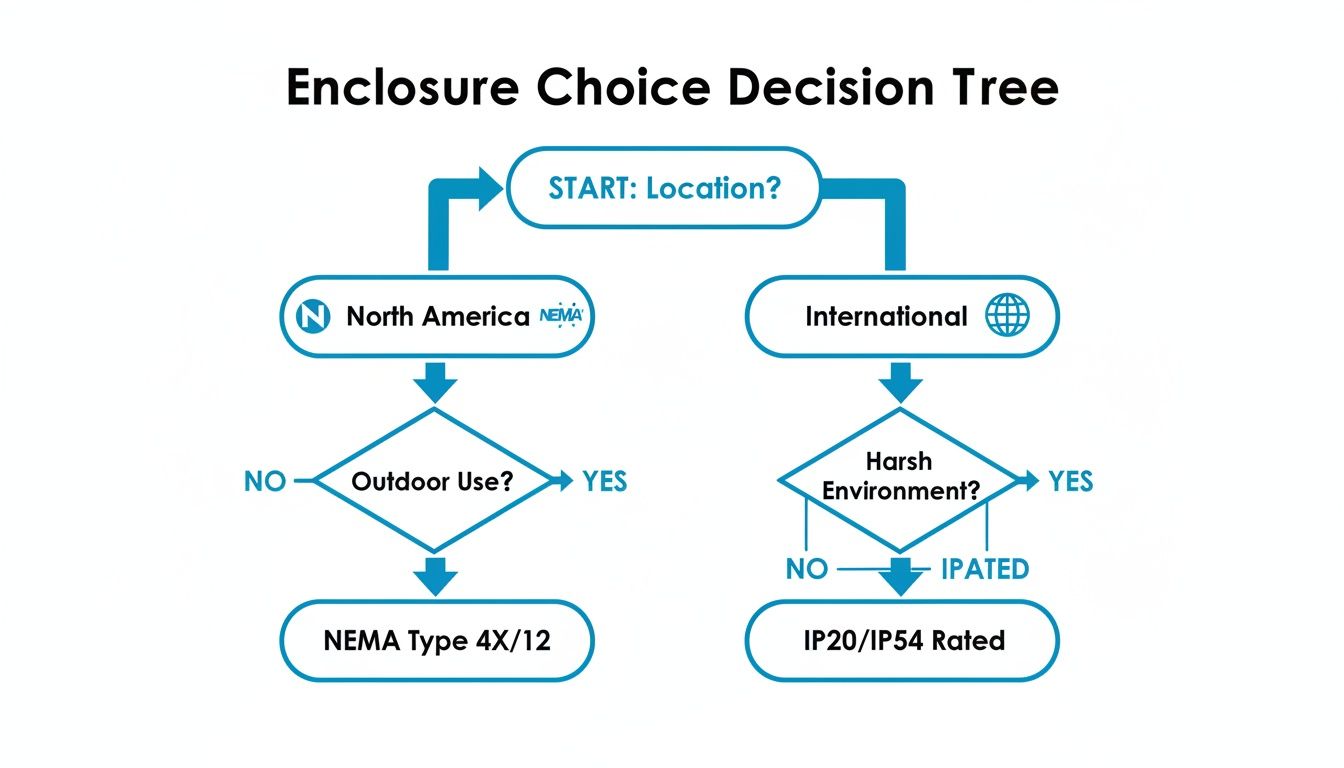
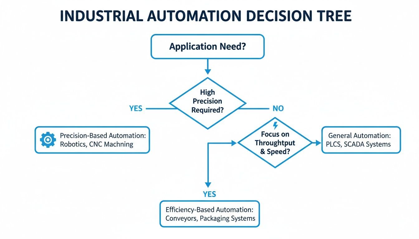
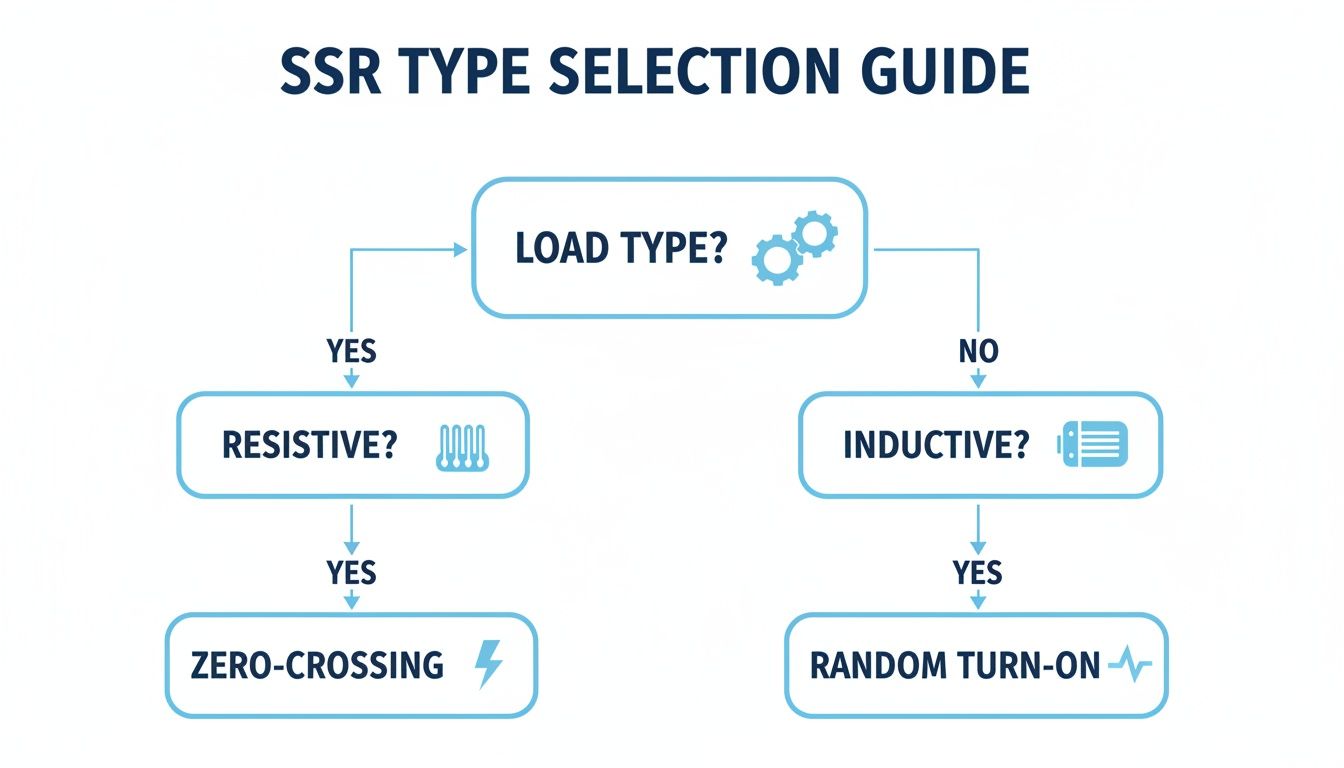
This decision tree gives you a great visual starting point for the selection process, helping you map out your needs based on the location and standards you're working with.
As the graphic shows, the first fork in the road is a big one: are you operating under North American (NEMA) standards, or do you need to meet international (IEC/IP) requirements?
Balancing Performance and Project Cost
At the end of the day, picking the right enclosure is all about finding that sweet spot between bulletproof protection and real-world project economics. Sure, a NEMA 4X stainless steel enclosure is the only real choice for a harsh marine environment, but it’s complete overkill for a clean, dry control room where a simple NEMA 1 box would do just fine.
Expert Tip: Don't just look at the sticker price—think about the total cost of ownership. A slightly pricier NEMA 4X enclosure that lasts for 15 years in a corrosive plant is a much smarter investment than replacing a cheaper NEMA 4 painted steel box every three years. Likewise, understanding the nuances between UL Listed vs. UL Recognized components can be critical for overall compliance and safety. By weighing these factors carefully, you can confidently choose an enclosure that will protect your critical assets for years to come.
Getting Materials and Customizations Right
A NEMA rating is only half the story. The material an enclosure is made from is just as critical to its long-term performance, especially out on the plant floor. Making the right choice here is the difference between an enclosure that does its job for years and one that fails prematurely.
Each option presents a unique trade-off between corrosion resistance, weight, and of course, cost. Think about it: a standard painted steel box might be fine in a climate-controlled room, but it won’t last a week in a washdown environment where a stainless steel unit is designed to thrive.
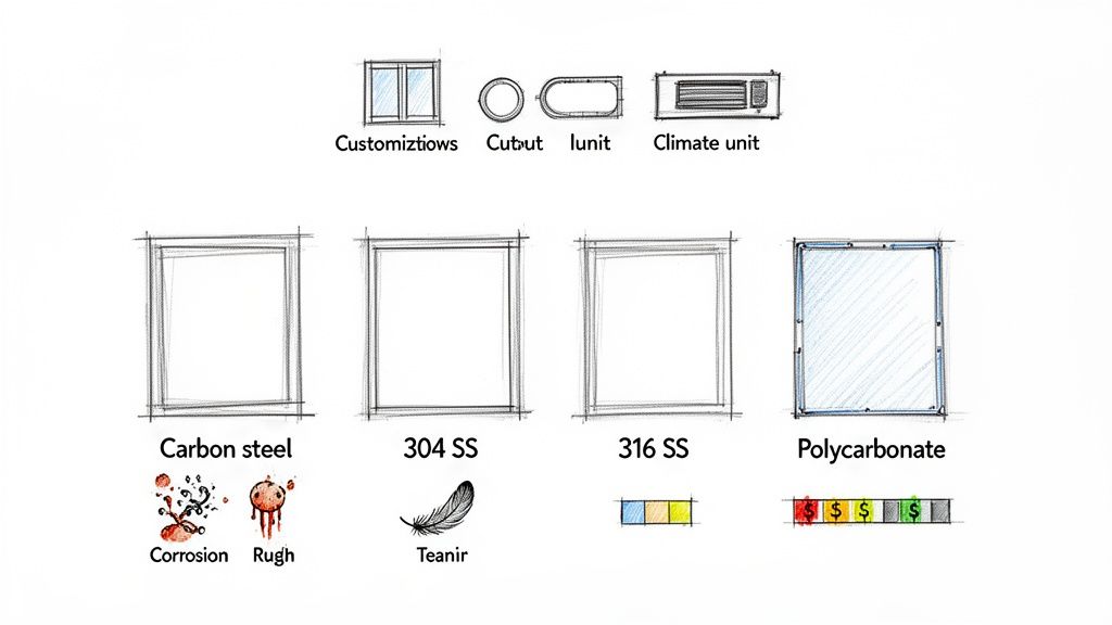
Common Enclosure Materials
Understanding the pros and cons of each material is the key to matching the enclosure to the job. These are the most common options you’ll run into:
Painted Carbon Steel: This is your workhorse for general-purpose indoor ratings like NEMA 1 and NEMA 12. It’s budget-friendly and the paint gives it a decent layer of protection. Just be aware that any scratch or ding can expose the steel underneath to rust.
Stainless Steel (304 & 316): When you see NEMA 4X, you should be thinking stainless. 304 stainless is the standard for food and beverage processing where washdowns are constant. For anything involving harsh chemicals or salt spray, you’ll want to step up to 316 stainless for its superior chloride resistance.
Aluminum: Lighter than steel and naturally resistant to corrosion, aluminum is a great middle-ground choice. It’s perfect for outdoor applications where you need durability without the weight of steel.
Polycarbonate: This high-impact plastic is a fantastic problem-solver. It’s lightweight, completely rust-proof, and easy to drill on-site. As a bonus, it’s transparent to radio waves, making it the go-to for housing Wi-Fi routers, VFDs, and other wireless gear.
Professional Modifications and How to Keep Your Rating
Let's be realistic—a stock enclosure straight out of the box rarely fits a project perfectly. You almost always need holes for conduit, cutouts for HMIs, or openings for pushbuttons. The catch? One bad drill hole can completely void an enclosure's NEMA rating.
Critical Point: Every single hole you add can break the seal. To keep a NEMA 4X rating intact, for example, every conduit hub, window, and latch you install must also be NEMA 4X rated and installed to spec.
This is exactly why certified UL panel shops are so valuable. These guys have the specialized tools and the know-how to make precise modifications without compromising the enclosure's integrity.
A good shop can handle things like:
Precision Cutouts: Using CNC machines to get perfectly sized holes and openings.
Component Installation: Professionally mounting everything from touch screens and windows to fans and air conditioners.
Custom Finishes: Applying special powder coats for extra protection or to match company branding.
Partnering with a certified expert is your best guarantee that a customized box will perform exactly as you need it to, keeping your equipment safe and your plant in compliance. For a deeper dive into the different types of electrical boxes available, our other guides can help you make an informed choice for both standard and custom projects.
Your Top NEMA Rating Questions, Answered
Working with NEMA enclosures day in and day out, we get a lot of great questions. When you're dealing with specifics like comparing two similar ratings or planning on-site modifications, it's easy to get tripped up.
This section tackles some of the most common questions we hear from plant engineers and packaging specialists. We want you to have the confidence to apply this knowledge correctly, ensuring everything you install is compliant, safe, and built to last.
NEMA 3R vs. NEMA 4: What’s the Real Difference?
The biggest difference boils down to how they handle dust and high-pressure water. Think of a NEMA 3R enclosure as your go-to for general outdoor use. It’s designed to keep out rain, sleet, and ice, but it’s not dust-tight. You’ll often find drainage holes in these to let condensation escape.
A NEMA 4 enclosure, on the other hand, is a completely sealed box. It’s fully dust-tight and can take a direct blast from a high-pressure hose, no problem. This makes it perfect for places that need regular washdowns or are exposed to a ton of windblown dust.
Can I Drill Into a NEMA Enclosure and Keep the Rating?
You can, but it absolutely must be done by a qualified professional if you want to maintain that rating. It's incredibly easy to compromise the enclosure's seal when you start drilling holes for conduit or cutting out a space for an HMI.
To do it right, any component you add—like fittings, buttons, or windows—has to meet or exceed the enclosure's original NEMA rating. So, if you have a NEMA 4X box, you need to use NEMA 4X fittings, and they must be installed and sealed perfectly.
Pro Tip: Your safest bet is always to work with a certified UL panel shop. They have the expertise to make sure every modification follows strict guidelines. This not only protects the NEMA rating and keeps your UL compliance intact but also prevents a simple mistake from causing a catastrophic equipment failure down the road.
Is It Okay to Use a NEMA 12 Enclosure Outside?
Absolutely not. A NEMA 12 enclosure is strictly for indoor industrial settings. It's a workhorse on the factory floor, offering solid protection against circulating dust, falling debris, and light drips of non-corrosive liquids.
But it has none of the seals or weather-resistant construction needed to survive outdoors. Rain, snow, sleet, and UV rays will destroy it. For any outdoor job, you have to step up to a rating built for the elements, like NEMA 3R, NEMA 4, or NEMA 4X.
When Is Stainless Steel Worth the Extra Cost?
You should always opt for stainless steel whenever corrosion is a potential issue. This is a no-brainer for environments with chemical exposure, salt spray (think coastal areas), or facilities that rely on frequent washdowns with harsh sanitizers. This is the world where NEMA 4X lives.
For general-purpose indoor spots or non-corrosive outdoor applications, painted carbon steel is a solid, cost-effective choice (think NEMA 12 or NEMA 3R). The paint does a good job protecting the steel, but if it gets scratched, rust will find a way in and eventually compromise the enclosure.
At E & I Sales, we're experts in helping you find and customize the right NEMA-rated enclosure for any job, making sure your critical systems stay protected. Get in touch with our team today to talk through your project needs.
At its core, a single-line diagram (SLD) is the electrical world's most effective shorthand. It uses a universal set of single-line diagram electrical symbols to map out the power flow in a system. Think of it as the master blueprint for an entire electrical installation, allowing engineers and technicians to grasp complex circuits at a glance—from the utility connection all the way down to a single motor—without getting bogged down by drawing every individual wire.
Decoding the Language of Electrical Schematics
A single-line diagram, often just called a one-line, offers a high-level, simplified view of an electrical system. Rather than cluttering the page with all three phases of an AC circuit, it condenses them into a single line. This elegant simplicity makes the diagram incredibly easy to read and is absolutely essential for everything from initial design and arc flash studies to everyday maintenance and troubleshooting.
For anyone working with industrial power systems, fluency in these core single-line diagram electrical symbols is non-negotiable. These graphical icons are the alphabet of our language, conveying vital information about every component and how it all connects. A well-drawn SLD gives you the complete picture, which is fundamental to working safely and efficiently.
The practical benefits of a good SLD are hard to overstate:
Enhanced Safety: It's the go-to document for lockout/tagout (LOTO) procedures. With it, you can confidently identify and isolate every power source before a single tool is picked up.
Operational Clarity: When something goes wrong, the diagram shows you exactly how the system is interconnected, making it invaluable for tracing faults or planning system upgrades.
System Analysis: Engineers use SLDs as the foundation for critical power system studies, including short-circuit analysis, protective device coordination, and load flow calculations.
This guide is designed to be your comprehensive visual dictionary. We'll dive into the most common symbols you'll encounter, explain what they do, and show you how they're used in the real world—in motor control centers (MCCs), switchgear, and UL-listed control panels.
To get started, it helps to group the vast library of symbols into a few main categories. This table gives you a quick overview of the key players on any SLD.
Common SLD Symbol Categories and Their Functions
Symbol Category
Primary Function
Example Components
Circuit Protection
Interrupt power flow during overcurrents or faults.
Circuit Breakers, Fuses, Relays
Transformers
Step voltage up or down between different parts of the system.
Power Transformers, Control Transformers
Conductors & Connections
Represent the path of power flow.
Cables, Busbars, Splices, Terminations
Switches & Disconnects
Manually connect or isolate circuits for operation or maintenance.
Disconnect Switches, Safety Switches
Loads
Consume electrical power to perform work.
Motors, Heaters, Lighting Panels
Metering & Instrumentation
Measure and display electrical parameters like voltage, current, and power.
Ammeters, Voltmeters, Power Meters
Understanding these basic groupings is the first step. From here, you can start to recognize how these individual components come together to form a cohesive system on paper.
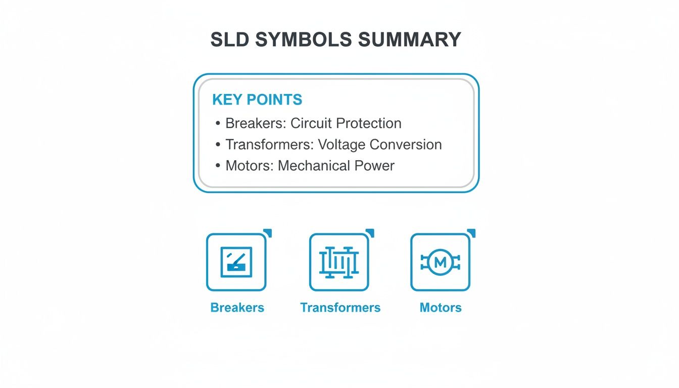
This graphic gives a great visual summary of some of the most fundamental symbols you'll see time and time again.
Each of these icons represents a core element: protection (breakers), power conversion (transformers), and the equipment doing the work (motors). These are the building blocks of almost any industrial SLD. Once you've got these down, you're well on your way to reading any electrical schematic that comes across your desk.
Why Standardized Electrical Symbols Are Critical
In any complex electrical system, clarity isn't just a convenience—it's the bedrock of safety and efficiency. Standardized single line diagram symbols electrical act as a universal language, wiping out the dangerous guesswork that leads to accidents. They ensure that an engineer in Tulsa and a technician in Berlin can look at the same schematic and understand the exact same story.
Think about it this way: a technician needs to perform emergency service on a critical motor control center (MCC). If the diagram uses some proprietary, non-standard symbols, they might mistake a circuit breaker for a simple disconnect switch. That one little mix-up could lead to them trying to open a circuit under a massive fault, triggering a catastrophic arc flash, destroying equipment, and causing severe injury.
Promoting Safety and Global Collaboration
This is why universal standards from bodies like ANSI (American National Standards Institute) and the IEC (International Electrotechnical Commission) are absolutely non-negotiable. For any company that takes safety and operational excellence seriously, these standards are the rule. Global OEMs and EPC firms, in particular, rely on them to allow their international teams to collaborate without a hitch, making design, review, and commissioning a much smoother process.
The whole concept of standardized symbols was a massive leap forward in engineering. It was pioneered by organizations like the IEC, IEEE, and ANSI to prevent the exact kind of chaos and danger that inconsistent drawings create. You can learn more about the history of electrical symbols and their development to see how far we've come.
A universally understood SLD is the first line of defense against electrical hazards. It ensures that every person interacting with the system, from the design engineer to the field technician, has a clear and unambiguous understanding of its configuration and potential risks.
Ensuring Compliance and Maintainability
Beyond the immediate safety concerns, sticking to these standards is essential for the long-term health of a system. For instance, if you're building UL-listed control panels, using the correct symbology is a fundamental requirement to get certified and pass inspection.
Years down the road, when that same facility undergoes a safety audit or needs a modification, that standardized documentation is what makes the job possible. It's a reliable, lasting record that future teams can trust. Without this common language, every service call or upgrade turns into a risky, time-consuming exercise in reverse-engineering.
Understanding Power Distribution and Conversion Symbols
Every single-line diagram starts with the power source. Think of these symbols as the very top of the electrical food chain, showing exactly where the power comes from and how it's converted for everything downstream. These are the foundational symbols you need to get right, as they set the stage for tracing the flow of energy from the grid all the way to a motor.
The most common starting point you'll see is the Utility Connection or Power Grid symbol. This little icon marks the exact point where the utility hands off power to the facility. You’ll almost always see it annotated with critical details like the incoming voltage and, just as importantly, the available fault current. That fault current number is a non-negotiable piece of information for any serious power system study.
Right after the utility feed, you're almost guaranteed to find a transformer. The transformer symbol is probably one of the most classic and recognizable single line diagram symbols electrical engineers work with daily.
Transformers: Stepping Voltage Up or Down
A transformer is a beautifully simple static device that uses electromagnetic induction to pass energy between circuits, usually to change the voltage. The standard symbol shows a couple of coils, but there are tons of variations that give you more detail—things like the winding connections (Delta or Wye) or the physical build (liquid-filled or dry-type).
Step-Down Transformers: These are the workhorses in most industrial and commercial settings. They take high utility voltages, like 13.8kV, and knock them down to a usable level for equipment, typically 480V.
Step-Up Transformers: As the name implies, these do the opposite. You'll find them where power is being generated, like at a plant with its own generators, to boost the voltage for efficient transmission over long distances.
The layout of a substation and where these transformers are placed is a whole discipline in itself. If you want to dive deeper, take a look at our guide on electrical substation design.
Generators and Busbars
If a facility has its own backup or primary power, a Generator Symbol will be on the diagram. It's usually just a circle with a "G" inside. This tells you there's an on-site source, like a diesel generator. Key specs like its kVA rating, voltage, and phase should always be noted right next to it.
A busbar is the main distribution hub inside a piece of switchgear or a motor control center. It’s basically a thick metal bar that provides a common connection point, letting multiple circuits tap into the same power source.
On an SLD, the busbar symbol is just a thick, heavy line, either horizontal or vertical. It’s simple but incredibly important. You'll see all the individual circuits branching off from this central bus. The busbar's voltage and amperage rating are crucial details that must be on the diagram to confirm it can handle the total load. Together, these source and distribution symbols form the bedrock of the entire diagram.
Identifying Circuit Protection and Switching Symbols
Think of protective and switching devices as the traffic cops and security guards of your electrical system. The symbols we use for these on a single-line diagram are absolutely critical for understanding how to isolate equipment for maintenance, kill power during a fault, or simply manage load connections. Getting these symbols right isn't just good practice; it's a fundamental skill for keeping everyone safe on the job.
These symbols are the bedrock of operational safety. They tell you exactly where and how a circuit can be de-energized. If you mistake a disconnect switch for a breaker, you could find yourself in a very dangerous situation, trying to open a device that simply isn't rated to handle the load.
Fuses and Disconnect Switches
Let's start with the basics: fuses and disconnect switches. These are your go-to components for simple protection and isolation. A fuse is a one-and-done overcurrent device; it's designed to melt and open the circuit when something goes wrong. On the other hand, a disconnect switch gives you a clear, visible air gap for isolation, but you should never open one under heavy load or fault conditions.
Fuse Symbol: You'll typically see this as a rectangle with a line running through it. Sometimes that line has a slight "S" curve. The most important annotation here is its amperage rating (e.g., 100A).
Disconnect Switch Symbol: This one is pretty intuitive—it’s a break in the line with a hinged segment that shows it can swing open. It always needs to be annotated with its voltage and amperage ratings.
In the real world, you'll often find these combined into a single unit called a fused disconnect switch, which handily provides both isolation and overcurrent protection.
Circuit Breakers and Contactors
Now for the dynamic duo of switching and protection: circuit breakers and contactors. They might look similar at a glance on an SLD, but their jobs are worlds apart. A circuit breaker is your automatic safety net, designed to trip during a fault. A contactor is more like a light switch, just a much bigger one, controlled remotely by a separate, low-power signal.
Expert Tip: Never confuse a breaker and a contactor on a diagram. A breaker is built to safely interrupt a massive fault current, potentially thousands of times its normal rating. A contactor is only meant to switch a load on and off under normal conditions. Using it to break a fault is a recipe for disaster.
Circuit Breaker Symbol: The classic symbol is a small square box right on the line. You might see additional markers to indicate special types, like draw-out breakers, which are standard in switchgear and motor control centers. Knowing the specific model, like an ABB circuit breaker, helps you understand its exact capabilities.
Contactor Symbol: A contactor is usually shown as two small parallel lines breaking the main power line, which represent its open contacts. This symbol is almost always paired with a coil symbol elsewhere on the control schematic to show how it's activated.
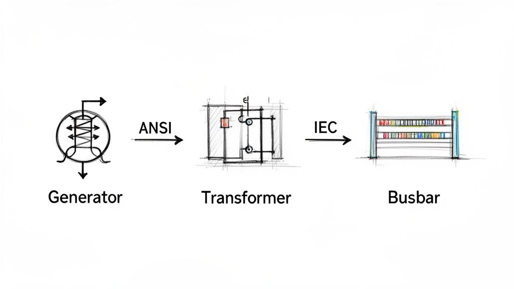
As you work with different drawings, especially from international projects, you'll notice differences between ANSI (American) and IEC (European/International) standards. Their symbols for the same device can be quite different, so it's vital to know which standard you're looking at.
ANSI vs IEC Common Symbol Comparison
When you're looking at schematics from different parts of the world, knowing the local dialect of symbols is key. The table below gives you a quick visual cheat sheet for some of the most common protection devices, comparing how they're drawn under ANSI and IEC standards.
Component
ANSI Symbol (Image/Description)
IEC Symbol (Image/Description)
Key Difference
Circuit Breaker
A small, simple square on the line.
A square containing an 'X' or other markers.
The IEC symbols tend to pack more functional detail into the main shape itself.
Fuse
A rectangle with a line passing completely through it.
A simpler rectangle, where the line doesn't extend past the ends.
The ANSI symbol is a bit more pictorial, looking more like a cartridge fuse in its holder.
Disconnect Switch
A break in the line with a hinged segment, showing the motion.
A simple T-shaped symbol on the line indicating an isolation point.
ANSI focuses on visualizing the physical action of opening the switch.
Pay close attention to these distinctions. Mixing them up can lead to a fundamental misunderstanding of how a system is designed to operate and be serviced safely.
Mastering Motor Load and Control Symbols
In any industrial plant, motors are the real workhorses. On a single-line diagram, their symbols are more than just placeholders; they're the core of the whole operation. These single line diagram symbols electrical representations tell you everything you need to know about power demands, control schemes, and the settings for protective gear.
The most common symbol you'll see is a simple circle with an "M" inside. That’s your motor. But the symbol alone isn't the whole story. You'll almost always find critical notes right next to it, like its horsepower (HP) or kilowatt (kW) rating, full-load amps (FLA), and operating voltage. Having that info right there is crucial for everyone, from the engineers designing the system to the technicians troubleshooting a breakdown on the floor.
Differentiating Motor and Load Types
While the basic "M" in a circle is a good start, a really well-drawn SLD gives you more detail. Different symbols can tell you exactly what kind of motor you're dealing with or distinguish it from other major electrical loads.
Three-Phase AC Induction Motor: This is your standard, go-to symbol—a circle with an "M." It's the most common type you'll encounter in the field.
DC Motor: This one also gets an "M" in a circle, but you'll see extra markings to show the armature and field windings. It’s a clear visual cue that you're looking at a direct current system.
Variable Frequency Drive (VFD): A VFD isn't a motor, but it controls one. Its symbol, usually a rectangle with a sine wave and an arrow, sits on the line right before the motor. This immediately tells you the motor's speed is adjustable.
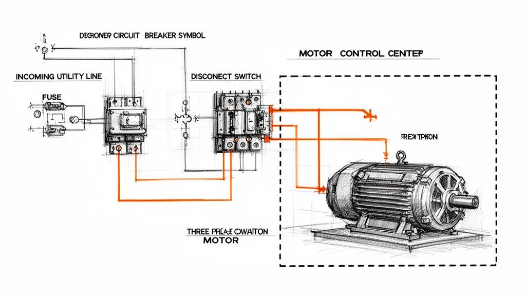
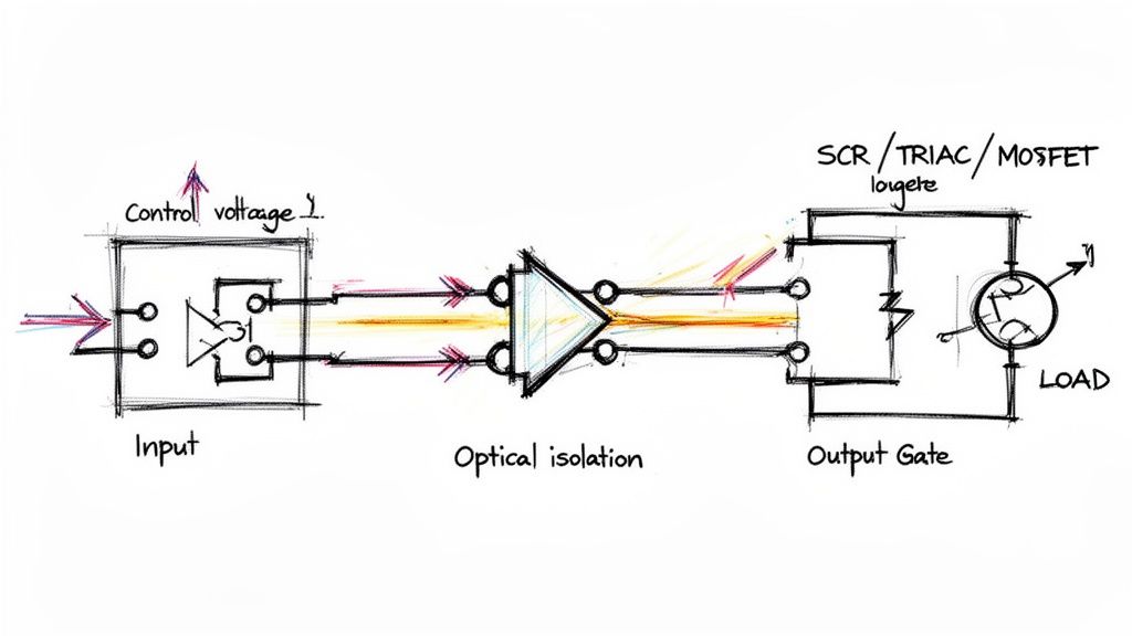
Take a look at this simple diagram. It perfectly shows the power path from the utility source, through the necessary protective devices, and down to the three-phase motor at the end.
You can see how the fuse and disconnect switch protect the motor load. This fundamental relationship between protection and the load is the basis for every SLD you'll ever read.
Connecting Loads to Control Systems
The motor symbol is just one part of a bigger picture. A useful SLD has to show how that motor is controlled and protected. You'll see lines connecting it back to the key components in its starter, which is especially important when you're looking at diagrams for a large piece of machinery or a whole Motor Control Center (MCC).
Every motor symbol on a diagram tells a story about its role in the larger system. It's linked to an upstream circuit breaker for fault protection, a contactor for on/off control, and an overload relay to protect against thermal damage. Understanding these connections is essential for safe and reliable operation.
For example, if you trace the line from the motor symbol, you'll work your way back through an overload relay (often shown as a curved line under a bimetallic strip symbol), then to a contactor, and finally up to a circuit breaker or fuse. This sequence lays out the complete power and protection path—an absolutely indispensable map for any engineer or technician.
Understanding Instrumentation and Protective Relays
A good single-line diagram does more than just trace the path of power. It has to show how the system is being watched and, critically, how it's protected from a catastrophic failure. This is where symbols for instrumentation and protective relays enter the picture. Think of these specialized single line diagram symbols electrical as the intelligence layer that keeps expensive assets like transformers and big motors from destroying themselves.
Instrumentation symbols are the easy ones. They represent the meters that give you real-time data. You'll see a circle with an "A" for an Ammeter (measuring current) or a "V" for a Voltmeter. These are the gauges operators need to confirm system conditions at a glance.
Protective relays, on the other hand, are the system's brain. These devices are purpose-built to spot abnormal conditions—overcurrent, short circuits, ground faults—and then automatically tell a circuit breaker to open. This all happens in milliseconds to isolate the problem.
Decoding ANSI Device Numbers for Relays
On North American drawings, you'll see protective relays identified by a standard set of numbers from ANSI/IEEE Standard C37.2. Each number points to a very specific protective function, and you'll find it inside the relay's circle symbol on the SLD. If you want to understand a modern protection scheme, you have to know these numbers.
Here are a few of the most common ANSI device numbers you'll run into constantly:
50 Instantaneous Overcurrent: This is the system's emergency brake. It trips with no intentional delay the second the current shoots past a high setpoint. Its whole purpose is to provide lightning-fast protection against major short circuits.
51 AC Time Overcurrent: You can think of this as the "timed overcurrent" relay. It waits for a specific, coordinated amount of time before tripping. This function protects against those sustained overloads that cook equipment over time.
87 Differential Protection: This is a highly sensitive and fast-acting scheme. The relay compares the current going into a piece of equipment (like a transformer or generator) with the current coming out. If they don't match, it means there’s a fault inside the equipment, and the relay trips immediately to limit the damage.
You'll very often see a "50/51" designation on an SLD. This just means a single modern, microprocessor-based relay is handling both the instantaneous (50) and time-overcurrent (51) jobs. It's a standard combination in today's digital relays.
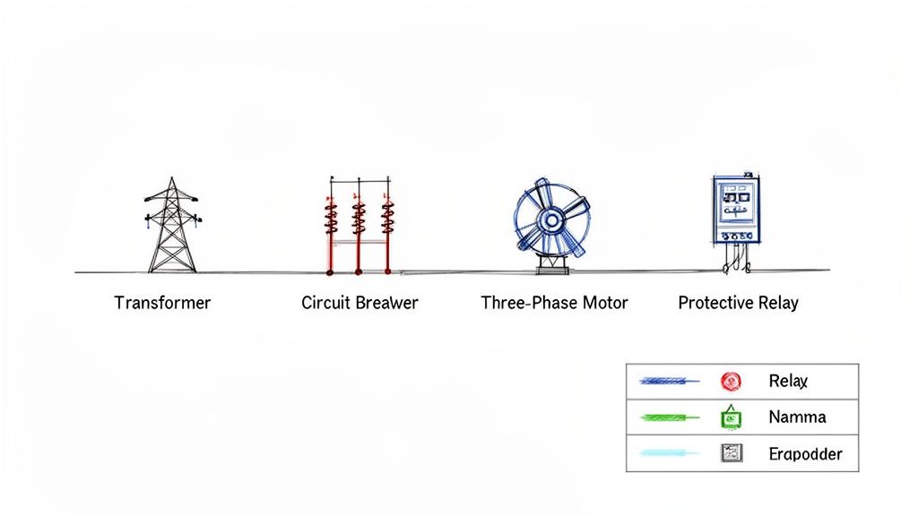
Single-line diagrams are the universal language for mapping out complex electrical systems everywhere, from factories to power plants. Engineers and technicians depend on dozens of these standard symbols to communicate everything from transformers and breakers to the sophisticated protection systems we've just discussed. For a broader overview of their role, check out Wikipedia's page on single-line diagrams.
Ultimately, these relay symbols are what let you verify that a system isn't just up and running, but is genuinely safe and built to withstand faults.
How to Annotate Single Line Diagrams Effectively
The symbols on a single-line diagram are just the starting point. It's the annotations—the notes and data—that turn a basic drawing into a working document that’s actually useful for engineers, electricians, and maintenance staff. A symbol without data is just a picture; a symbol with the right data is a tool.
Think about it this way: a circuit breaker symbol tells you what it is, but an annotation tells you its frame size, trip rating, and interrupting capacity. That’s the critical detail you need for everything from commissioning and troubleshooting to performing an arc flash study. Getting the annotations right is non-negotiable for safety and functionality.
Essential Annotation for Key Components
To create a truly professional SLD, you have to include specific details for the major equipment. This isn't just good practice; it's what makes the diagram a reliable source of truth for anyone who needs to work on that system.
Here are the must-haves for common single line diagram symbols electrical components:
Transformers: Always specify the kVA rating, primary and secondary voltages, the winding connection (like Delta-Wye), and the percent impedance (%Z).
Circuit Breakers: You absolutely need the ampere frame (AF), ampere trip (AT), and the short circuit interrupting capacity (AIC or kAIC).
Motors: Be sure to note the horsepower (HP) or kilowatt (kW) rating, full load amps (FLA), and the operating voltage.
Cables and Wires: Detail the conductor size (AWG or kcmil), material (copper is standard, but you'll see aluminum), insulation type, and how many conductors run per phase.
An SLD is more than just a drawing; it’s a core piece of technical documentation. For more on the bigger picture of documentation, you might find this guide on creating better technical documentation helpful. It reinforces how clear, detailed information turns a good drawing into great project documentation.
A well-annotated diagram is a proactive safety tool. It equips technicians with the precise information they need to verify equipment ratings and perform lockout/tagout procedures correctly, significantly reducing the risk of accidents.
Finally, a simple but powerful habit is to cross-reference other relevant drawings. Add notes pointing to panel schedules, control schematics, or equipment layout plans. This connects the SLD to the rest of the documentation set, making it much easier for someone to navigate a complex project and track down issues when something goes wrong.
Frequently Asked Questions About SLD Symbols
Even after you've got a handle on the individual symbols, real-world questions always pop up when you're in the field. This section tackles some of the most common things we hear from engineers, technicians, and project managers who work with single-line diagrams every day.
What’s the Main Difference Between ANSI and IEC Symbols?
The biggest difference comes down to geography and graphic style. ANSI (American National Standards Institute) symbols are what you'll almost always see in North America. They often look a bit more like a simplified picture of the actual component.
On the other hand, IEC (International Electrotechnical Commission) symbols are the standard in Europe and most other parts of the world. These tend to be more abstract, using simple geometric shapes to represent components.
While they do the exact same job, a device can look totally different depending on the standard. A classic example is a circuit breaker: the ANSI symbol is a plain square, while the IEC version is a square with an 'X' inside. The first thing you should always do is check the drawing’s title block to see which standard is being used.
How Do I Read a Complex Motor Control Center SLD?
Don't get overwhelmed. The trick is to follow the power, starting from the top and working your way down.
Find the Source: First, locate the main incoming power feed, its main protective device (breaker or fuse), and the main horizontal busbar that feeds the whole MCC.
Follow the Vertical Bus: From the main bus, trace the power down a vertical bus to an individual motor starter unit, which everyone just calls a "bucket."
Inspect the Bucket: Inside that specific unit, follow the circuit path through its local breaker or fuse, then the contactor, and finally the overload relay before it heads out to the motor.
Always pay close attention to the notes next to the motor symbol. That’s where you’ll find the critical data—horsepower (HP), voltage, and full-load amps (FLA)—which is essential for any kind of troubleshooting or maintenance work. Following this path from source to load is a fundamental skill for confirming protection schemes and carrying out safe lockout/tagout procedures.
Where Can I Find Downloadable Libraries of Electrical Symbols?
Most professional-grade CAD platforms for electrical design come packed with extensive symbol libraries right out of the box. Software like AutoCAD Electrical, EPLAN, and SolidWorks Electrical are the industry go-tos and have you covered for both ANSI and IEC standards.
You can also get symbols directly from the source. Major manufacturers like Schneider Electric, Siemens, and Rockwell Automation usually offer free, downloadable CAD blocks for their specific products on their websites. This is perfect when you need to show a particular model of a VFD or breaker. For more generic libraries, various online CAD repositories are also a great resource.
At E & I Sales, we specialize in turning complex schematics into functioning systems. From the motors and drives to the custom UL-listed control panels that run them, we provide the integrated hardware that brings your single-line diagrams off the page and onto the plant floor. Discover how our expertise can support your next project.
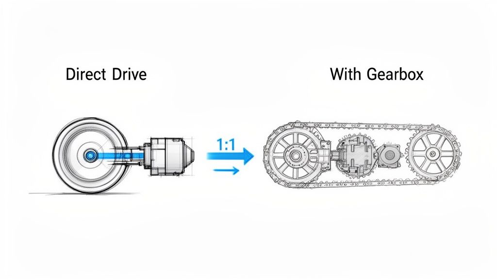
Ever felt the frustrating "slop" or backlash in a machine? That tiny bit of play in a gear or a belt that throws off precision? Direct drive motors are the answer.
Instead of relying on clunky gearboxes, belts, or chains, a direct drive motor connects straight to the load it needs to move. It’s a clean, simple, and incredibly efficient way to transfer power with a perfect 1:1 ratio. This direct connection is a game-changer for precision and reliability in modern automated machinery.
What Is a Direct Drive Motor?
Think about the difference between a high-performance electric car and a standard gas-powered one. In the EV, power flows almost instantly from the motor to the wheels. The gas car, however, sends power through a complex transmission filled with gears and shafts, each one a potential point of failure or energy loss.
A direct drive motor works like that electric car, giving you an immediate and efficient transfer of energy.
By physically coupling the motor’s rotor directly to the component you’re trying to move, you get rid of all the in-between mechanical parts. This elegant simplicity is its biggest advantage. No gears means no backlash messing with your positioning. No belts means no tensioning, slipping, or replacements to worry about.
The Core Design Philosophy
The leap to direct drive isn't just a small improvement; it's a completely different way of approaching motion control. It's about trading a system of many complicated parts for a single, integrated unit. The payoff is huge:
Pinpoint Precision: With zero backlash, you get incredibly accurate and repeatable positioning. This is non-negotiable for equipment like CNC machines and high-speed robotics.
Serious Efficiency: Without the friction from a gearbox or belt system, direct drive motors can hit efficiency ratings over 95%. That's power going straight to the work, not wasted as heat.
Lower Maintenance: Fewer moving parts means fewer things to wear out, lubricate, or replace. The result? A massive reduction in downtime and labor costs.
Smaller Footprint: Getting rid of bulky transmissions lets you build smaller, more streamlined machines.
By delivering power straight to the load, a direct drive motor creates a system that is mechanically stiff, highly responsive, and inherently more reliable. This direct connection is the key to achieving a level of performance that traditional systems struggle to match.
The market is taking notice. The global direct drive motors market hit USD 6.5 billion thanks to huge demand from automation and robotics. It’s on track to more than double, reaching USD 12.8 billion by 2033, growing at a solid 7.9% CAGR.
To get a better handle on what makes this technology tick, it helps to look at how performance is squeezed out of other motor types, like the high performance electric motors used in specialized EVs. The same core principles of maximizing torque and efficiency apply. Ultimately, direct drive motors are setting a new bar for modern automation, clearing the way for faster, more precise, and more dependable machinery.
Direct Drive vs Traditional Drive Systems At a Glance
So, how do these systems really stack up against each other? This table breaks down the fundamental differences at a high level, making it clear where each one shines (or doesn't).
Attribute
Direct Drive System
Geared System
Belt-Driven System
Mechanical Complexity
Very Low
High
Moderate
Efficiency
Very High (95%+)
Moderate (70-90%)
Good (85-95%)
Precision & Accuracy
Excellent (No backlash)
Good (Has backlash)
Fair (Belt stretch/slip)
Maintenance
Minimal
High (Lubrication, wear)
Moderate (Tensioning, replacement)
Speed/Torque
High torque, low speed
High torque, variable speed
Flexible speed, lower torque
Acoustic Noise
Very Low
High
Low to Moderate
System Footprint
Compact
Bulky
Can be large
As you can see, while traditional systems still have their place for certain applications, direct drive technology offers a clear advantage when precision, efficiency, and low maintenance are your top priorities.
How Direct Drive Actually Pays Off on the Production Floor
Knowing the theory behind a direct drive motor is one thing, but watching it transform a real-world production line is where the lightbulb really goes on. For plant engineers and system integrators, the appeal goes way beyond the specs. We're talking about real, measurable business outcomes—less scrap, smaller energy bills, and machines that just run.
Let's break down these advantages by looking at the common headaches they solve.
Unlocking a New Level of Precision and Quality
Think about a high-speed CNC machine grinding out intricate medical parts where tolerances are microscopically tight. With a classic geared system, you're always fighting backlash—that tiny bit of play between gear teeth. It might seem small, but it introduces positioning errors that lead directly to rejected parts, wasted material, and blown production costs.
Now, swap in a direct drive motor. By connecting the motor straight to the machine's lead screw, you eliminate all that mechanical slack. The system becomes incredibly stiff and responsive, turning every command from the controller into precise, repeatable motion. The result? A perfect surface finish, flawless part geometry, and a scrap rate that drops through the floor. This isn't just a minor improvement; it's how you build a competitive edge based on quality.
When you remove the mechanical middlemen—the gears, belts, and couplings that create backlash and compliance—a direct drive motor delivers a level of precision that's simply out of reach for traditional systems. This has a direct impact on product quality, cuts material waste, and boosts throughput.
This kind of precision is exactly why the technology is taking off. The direct drive rotary motor market is on a tear, projected to hit USD 8.444 billion by 2025. That growth is fueled by integrators and plant managers who need simpler motor controls and rock-solid reliability to hit their production goals. You can get a deeper look at the market trends for direct drive motors and see how they're driving efficiency across industries.
Slashing Energy Costs Where It Counts
Every facility manager has operational expenses in their crosshairs, and energy consumption is always a big target. Take a massive conveyor system in a distribution center running around the clock. A belt- or chain-driven setup is constantly bleeding energy through friction and mechanical loss. You can feel it as heat and hear it as noise, but on the balance sheet, it's just wasted money.
A direct drive motor completely rewrites that math. By getting rid of the transmission hardware, it can hit an efficiency rating of over 95%. That means almost every watt of electricity gets converted into useful work. For that same conveyor system, making the switch to direct drive can deliver a serious, measurable drop in kilowatt-hour usage, putting money back into the budget month after month.
Taking the Maintenance Burden Off Your Team
Picture a busy packaging line where a critical machine depends on a gearbox. The maintenance schedule is a constant grind of oil checks, lubrication, and planning for the next inevitable gearbox replacement. An unexpected failure brings everything to a halt, sending the maintenance team scrambling for hours while the line sits idle. That reactive fire-fighting drains resources and kills productivity.
A direct drive motor just erases those failure points. There’s no gearbox oil to change, no belts to tighten, and no chains to lube. The maintenance workload shrinks dramatically, freeing up your skilled techs to focus on proactive improvements instead of just patching things up. This doesn't just cut maintenance costs; it boosts your Overall Equipment Effectiveness (OEE) by keeping the machines running. For any plant engineer, that’s the definition of a smoother, more predictable operation.
How to Select the Right Direct Drive Motor
Picking the right direct drive motor isn’t as simple as grabbing a standard NEMA-frame motor off the shelf. Because this component becomes a core part of your machine's structure—not just a bolt-on part—the selection process has to go much deeper. You're balancing raw performance, mechanical fit, and long-term reliability all at once.
Think of it less like choosing a motor and more like designing a custom powertrain. You wouldn't put a drag racing engine in a rock crawler, right? The same logic applies here. You need to intimately understand your load, your motion profile, and the physical space you have to work with. Get this right, and you unlock the incredible precision and power that direct drive offers.
Often, the whole decision boils down to a fundamental choice: are you chasing ultimate precision or maximum efficiency?
As you can see, there's a clear path. Your end goal—whether it's hitting a micron-level target or just slashing energy bills—will point you toward the best technology for the job.
Analyzing Your Torque Requirements
First thing's first: you absolutely have to nail down your torque requirements. Getting this wrong is probably the most common (and costly) mistake we see. In the world of direct drive, torque is a two-part story: continuous torque and peak torque.
Continuous Torque (RMS): This is the workhorse spec. It’s the average muscle the motor needs to flex during a normal cycle just to keep things moving against friction and gravity. This number is the biggest driver of the motor's physical size and how much heat it’s going to generate.
Peak Torque: Think of this as the motor’s adrenaline shot. It's the maximum force needed for those brief, intense moments of acceleration and deceleration. If you undersize for peak torque, you're asking for stalls and faults when the machine is pushed hardest.
You really need to map out your entire motion profile—the ramps up, the constant speed cruises, and the ramps down. It’s worth spending the time here. If you need a refresher, you can learn more about torque calculation for motors in our guide to make sure your calculations are rock solid.
Matching Motor and Load Inertia
Inertia—an object’s stubborn resistance to speeding up or slowing down—is a huge deal in high-performance servo systems. The key metric is the inertia ratio, which compares the inertia of your load to the inertia of the motor's rotor. A bad mismatch here is a recipe for disaster, leading to overshoot, ringing, and sloppy control.
A good rule of thumb for direct drive systems is to keep the load-to-motor inertia ratio below 10:1. While direct drive is inherently more stable than a geared system, staying in this ballpark is what gives the servo drive the authority it needs to keep the load under tight control for crisp, precise movements.
It’s like trying to steer a massive barge with a tiny outboard motor. The motor (the rudder) just doesn't have enough control over the barge's momentum (the load inertia). A low inertia ratio is like having a properly sized rudder—you get instant, predictable control.
Mechanical and Environmental Considerations
Beyond pure performance numbers, you have to think about how this motor will physically live inside your machine. This is where you get into the nitty-gritty of mounting, bearings, and making sure the motor doesn't cook itself.
Mounting and Form Factor
Direct drive motors generally come in two flavors, each with its own pros and cons:
Frameless (Kit Motors): This is the pure, minimalist approach. You get a separate rotor and stator and design them right into your machine’s housing. It’s the ticket to the most compact and rigid setup possible, but it puts more of the engineering burden on you for alignment and bearing support.
Housed Motors: These are much closer to a conventional motor—a self-contained unit with its own housing, bearings, and shaft. They are far simpler to bolt on and get running, but you sacrifice some of the design compactness you’d get with a frameless motor.
Bearing and Thermal Management
Remember, the motor is directly connected to the load. That means the motor's bearings are now responsible for supporting the full weight and operational forces of your payload. Always double-check that the motor’s specified axial and radial load ratings can handle what you’re throwing at them.
Finally, don’t forget about heat. A motor's continuous torque rating is entirely dependent on its ability to stay cool. Make sure your design has a plan for heat dissipation, whether it's simple convection, a fan, or even a liquid cooling loop for those really demanding, high-duty-cycle applications. Overheating is a surefire way to kill a motor’s performance and shorten its life.
Integrating Motors with Your Control Systems
A high-performance direct drive motor is only half the story. You can have the best motor in the world, but its real power is only unleashed when you pair it with the right control system. The relationship between the motor and its servo drive or Variable Frequency Drive (VFD) is everything—it’s the brain and central nervous system of your entire machine.
Getting this pairing right is what separates a world-class machine from a constant headache. It’s all about matching the right components, fine-tuning the software, and making sure everything talks to each other flawlessly to execute perfect motion, every single time.
Choosing the Right Feedback Device
Before a control system can tell a motor what to do, it needs to know exactly where the motor is. That’s the job of the feedback device, which acts as the system's eyes and ears. The two most common options are encoders and resolvers, and your choice really boils down to your application's environment and how much precision you need.
Encoders: These are your high-resolution digital specialists. If you need extreme accuracy for something like CNC machining or semiconductor manufacturing, an encoder is the way to go. They deliver incredible precision but can be a bit sensitive to tough conditions like heavy vibration or contamination.
Resolvers: Think of resolvers as the rugged old pros of feedback. They're analog devices that are built like a tank, capable of handling extreme temperatures, shock, and dirty environments without breaking a sweat. While they might not have the razor-sharp resolution of a high-end encoder, their sheer durability makes them the go-to choice for heavy-duty jobs like stamping presses or steel mills.
It's that classic trade-off: precision versus toughness. You have to take a hard look at where the machine will live and operate to make sure the feedback device will keep sending reliable data for years.
The Art of Servo System Tuning
Once you've physically connected the motor and feedback device to the drive, the real magic begins. This is where tuning comes in. It’s the process of adjusting the control loops—usually the proportional, integral, and derivative (PID) gains—inside the drive so the motor’s response perfectly matches the load it’s moving.
Think of it like setting up the suspension on a race car for a specific track. A poorly tuned system will feel sloppy and out of control, causing the machine to overshoot its target, oscillate, or just feel sluggish. But when you nail the tuning, the machine becomes crisp, accurate, and incredibly stable. It settles into position instantly with zero wasted motion. This step is absolutely critical if you want to get every last bit of dynamic performance out of your direct drive motor.
A well-tuned servo system is the cornerstone of high-performance automation. It ensures the machine responds instantly and accurately to commands, directly impacting product quality, throughput, and operational efficiency. Neglecting this step means leaving significant performance on the table.
Ensuring Seamless Communication and Safety
Your direct drive motor and its controller don't work in a bubble. They need to communicate with the rest of your automation system, like the Programmable Logic Controllers (PLCs) running the show and the Human-Machine Interfaces (HMIs) operators use. This demands a solid communication protocol, like EtherNet/IP or PROFINET, to keep real-time data flowing. For a deeper dive into how drives fit into the big picture, our guide on the role of a motor variable speed controller in modern systems is a great resource.
But the most important piece holding all this together is the UL-listed control panel. This isn't just a metal box to stick your components in; it’s an engineered safety system that ensures everything is wired correctly, protected from faults, and compliant with national safety standards. A well-designed, custom-built panel provides reliable power distribution, overcurrent protection, and a safe operating environment.
Honestly, working with a single integrator who can deliver the whole package—the motor, the drive, and the certified UL-listed panel—is a game-changer. It gets rid of the finger-pointing that happens when you source parts from different vendors. You get a complete system that’s designed, built, and tested to work together from day one, which helps you sidestep those costly integration nightmares and project delays that can completely derail a production schedule. It’s a holistic approach that guarantees safety, compliance, and rock-solid reliability.
Getting Installation and Troubleshooting Right
A direct drive motor is only as good as its installation. Period. Unlike a forgiving belt or chain system that can mask minor imperfections, a direct connection demands precision. Getting the installation right isn't just about making the machine run—it's the bedrock of long-term reliability and your first line of defense against premature, costly failures.
Think of it like building a house. A slightly off-kilter foundation creates huge problems for the framers, the roofers, and everyone else down the line. It's the same with a direct drive motor; nail the alignment and mounting, and you're setting it up for a long, smooth operational life.
This is the field-level advice you need—from proactive installation steps to reactive troubleshooting—to keep your equipment humming and maximize uptime.
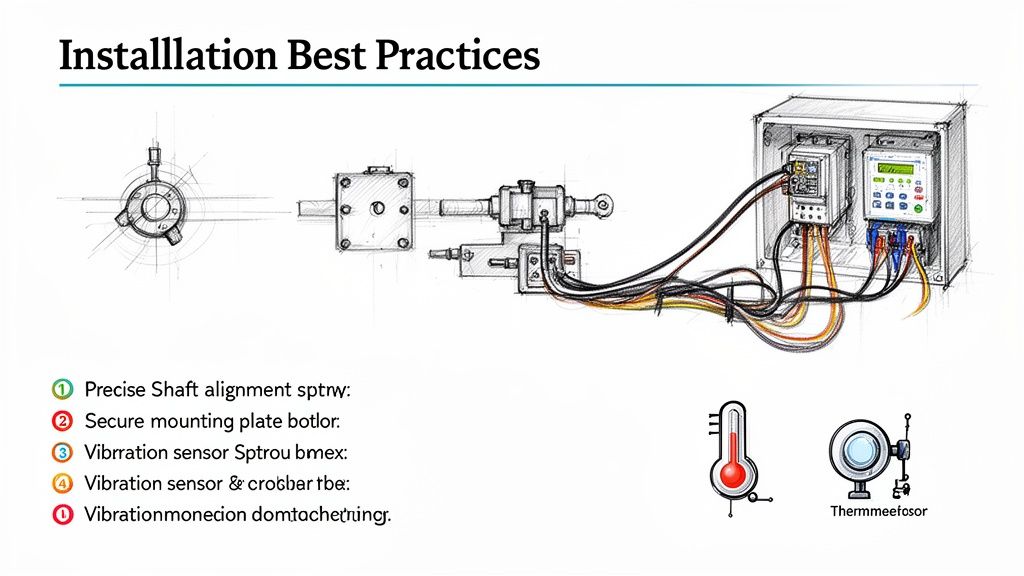
Critical Installation Checklist
Your best weapon against future downtime is meticulous attention during the initial setup. A few thousandths of an inch of misalignment might not seem like much, but it's enough to introduce killer stresses that will chew up bearings and cause vibration issues.
Stick to this checklist for a flawless installation:
Verify Mounting Surfaces: Before you even think about lifting the motor, get down and inspect the mounting surfaces. Are they perfectly flat, rigid, and clean? Any burrs, old gasket material, or unevenness will create a stress point the second you tighten the bolts.
Nail the Alignment: Break out the precision tools—laser alignment systems, dial indicators, whatever it takes. The motor shaft and the driven load have to be perfectly concentric and parallel. This is the single most important step for preventing premature bearing wear.
Secure All Fasteners: Don't just "get 'em tight." Use a calibrated torque wrench and tighten every mounting bolt to the manufacturer's exact spec. If they recommend a thread-locking compound, use it. Vibration has a knack for loosening things you thought were secure.
Confirm Electrical Connections: Go through all power, feedback, and communication wiring twice. Connections must be tight, shielded from electrical noise (keep them away from high-voltage lines!), and properly terminated. A loose wire is one of the most common culprits behind erratic motor behavior.
Troubleshooting Common Failure Modes
Even a textbook installation can't prevent every issue. The key is knowing what to look for so you can diagnose problems fast and minimize disruption. When a direct drive motor starts acting up, it usually gives you clues.
A sudden spike in temperature or a new vibration is your machine's early warning system. Jump on those symptoms immediately. It’s a lot easier than dealing with a catastrophic failure that shuts down the entire line.
Here are the most common headaches and what's likely causing them.
Issue 1: Excessive Heat or Overheating A hot motor is a stressed motor. It's often the first red flag signaling a deeper mechanical or electrical problem.
Likely Causes:
Mechanical Binding: The load is fighting back. Something is causing more friction than expected, maybe from misalignment or a problem in the driven components.
Incorrect Drive Parameters: Check the servo drive settings. If the current limit or tuning gains are cranked too high, you're essentially forcing the motor to body-slam the load on every move.
Insufficient Cooling: Are the vents blocked? Is the cabinet fan working? Heat has to go somewhere, and if it can't escape, it will cook the motor. Good protection of motors always starts with smart thermal management.
Issue 2: Unwanted Vibration or Noise A healthy direct drive system is smooth and quiet. If you hear or feel a new vibration, it’s time to investigate.
Likely Causes:
Mechanical Imbalance: The problem might not be the motor but the load it's attached to. An unbalanced load creates a cyclical vibration that gets worse with speed.
Loose Components: Go back and check every single mounting bolt and coupling. You'd be surprised how much noise a single loose fastener can make.
Servo Tuning Instability: If the drive's PID loops are poorly tuned, the motor can start to oscillate or "hum" as it fights itself to hold a position. This is often a software fix—a quick re-tune can solve it.
Issue 3: Positioning Errors or Inaccuracy The motor isn't hitting its marks, overshooting the target, or seems to be off by a consistent amount. The issue is almost always in the control loop.
Likely Causes:
Feedback Device Issues: The drive is flying blind. A loose encoder, a nicked cable, or electrical noise scrambling the signal can corrupt the position data the drive relies on.
Mechanical Backlash (in the load): The motor itself has zero backlash, but that doesn't mean the rest of your machine doesn't. Check downstream couplings, gearheads, or actuators for any slop.
Incorrect Tuning: A sluggish or overly aggressive tuning profile will cause consistent positioning errors. The system is either too slow to react or too jumpy to settle accurately.
Your Direct Drive Motor Questions, Answered
Jumping into any new technology brings up questions. It's only natural. For OEMs, plant engineers, and anyone looking to boost machine performance, getting the right answers about direct drive motors is the first step toward a successful project.
Let's cut through the noise and tackle the most common questions we hear from the field.
Are Direct Drive Motors Really More Expensive Than Geared Systems?
This is always question number one, and for good reason. If you just look at the upfront price tag, a direct drive motor can seem more expensive than a standard motor and gearbox combo. But that’s only a tiny piece of the puzzle.
You have to look at the Total Cost of Ownership (TCO). A direct drive system completely gets rid of gearboxes, couplings, belts, and pulleys. That’s a shorter bill of materials right there, not to mention less inventory to manage.
The real savings, though, come over the life of the machine. Think about it: no more worn-out gears, no more stretched belts, and no more scheduled lubrication. Maintenance costs plummet. Add in their incredible energy efficiency—often over 95%—and you’ll see the difference on your electricity bill.
When you can't afford a single minute of downtime and precision is everything, the math almost always works out. The reduced maintenance and energy savings mean a direct drive motor pays for itself, delivering a much lower TCO and a faster return on your investment.
Where Do Direct Drive Motors Make the Most Sense?
Direct drive motors are absolute game-changers in applications where precision, speed, and rock-solid reliability are make-or-break. They shine wherever the mechanical "slop" and backlash from a traditional transmission system is causing quality problems or limiting how fast you can run.
We see them deliver huge results in places like:
CNC Machining: To get those flawless surface finishes and hold incredibly tight tolerances that backlash makes impossible.
Robotics: For precise, repeatable movements, cycle after cycle, without the positioning errors that pop up as gears wear down.
High-Speed Packaging and Sorting: To keep products moving quickly and ensure everything lands exactly where it needs to, every time.
Indexing Tables and Turrets: For lightning-fast, accurate positioning in automated assembly lines.
Bottom line? If your machine suffers from the wear, tear, and maintenance headaches of a traditional gearbox or belt drive, it's a prime candidate for a direct drive upgrade. They are especially powerful in automated systems where tweaking a gearbox is a nightmare and downtime costs a fortune.
How Do I Size a Direct Drive Motor Correctly?
This is where the engineering really comes in. Sizing a direct drive motor isn't like picking a standard motor off the shelf; it requires a deep dive into your application's specific motion profile. Getting this right is absolutely critical.
You have to nail down a few key parameters:
Peak Torque: What's the absolute maximum torque you need for the toughest part of the job, usually the acceleration and deceleration phases?
Continuous (RMS) Torque: What's the average torque needed to keep things running smoothly and overcome friction throughout the entire work cycle?
Load Inertia: This is a big one. The ratio of the load's inertia to the motor's rotor inertia is crucial for stable control. A load-to-motor inertia ratio under 10:1 is a good target to shoot for.
Maximum Speed: How fast does this thing really need to go?
Mechanical Constraints: You have to consider the physical space you have to work with and make sure the motor’s bearings can handle the unique axial and radial loads of your machine.
Because there are so many variables, it's a smart move to work with an experienced integrator. An expert can run the numbers, analyze your machine's dynamics, and help you select the perfect motor and drive combination for the job.
Can I Swap Out My Old Geared Motor for a Direct Drive?
Absolutely. Retrofitting an existing machine with a direct drive motor is a fantastic way to breathe new life into it and unlock more performance. But it's rarely a simple drop-in replacement.
First, you'll have to tackle the mechanical side by designing a new mounting solution to connect the motor directly to your load, ensuring perfect alignment. Electrically, you’ll definitely need a new servo drive that's properly matched to the motor. And finally, your control system will need to be re-tuned to take full advantage of the motor's incredibly fast response and stiffness.
It's an engineering project, no doubt about it. But the payoff in precision, energy savings, and massively reduced maintenance often makes it one of the best investments you can make in your equipment.
At E & I Sales, we don't just sell parts; we engineer complete solutions. From sizing and selecting the right motor to designing and building custom UL-listed control panels, our team is your single source for making sure your direct drive system performs flawlessly from day one. https://eandisales.com
A solid state relay, often just called an SSR, is an entirely electronic switch. It lets you control a large, high-power electrical load using just a tiny, low-power signal. Unlike the chunky mechanical relays you might be used to, an SSR has absolutely no moving parts.
It’s best to think of it as a silent, lightning-fast digital switch that works with incredible precision.
Unpacking the Solid State Relay
At its heart, an SSR is the modern answer to a classic engineering problem: how do we switch a circuit on and off more reliably? The solution is in its solid-state design. Instead of a physical contact physically closing, a small electrical signal triggers an internal optical sensor. This, in turn, tells a powerful semiconductor—like a TRIAC or a MOSFET—to let the main power flow through.
This completely contactless design is where all the magic happens. By getting rid of moving components, you eliminate the mechanical wear and tear that inevitably kills traditional electromechanical relays (EMRs). An SSR can perform millions upon millions of cycles without breaking a sweat, giving it a ridiculously long operational life.
From Mechanical Clicks to Silent Switches
You know that audible "clack" an old thermostat or a big industrial contactor makes? That's the sound of metal contacts physically smacking together. An SSR, on the other hand, operates in total silence. This is a huge deal in noise-sensitive places like hospitals or quiet control rooms.
But the silence is just the start. For those of us in industrial settings, this lack of mechanical action brings some serious advantages:
Extreme Durability: With no physical parts to fatigue or break, SSRs just shrug off shock and vibration. They're perfect for the rugged, unforgiving environment of a manufacturing floor.
Blazing-Fast Switching: We're talking microseconds. An SSR can turn on and off far faster than any mechanical device could ever hope to. This speed is non-negotiable for applications needing tight control, like PID temperature loops in industrial heaters or high-frequency motor drives.
Reduced Electrical Noise: The semiconductor switch is designed to turn on and off smoothly, which creates significantly less electromagnetic interference (EMI). That means less noise to potentially disrupt other sensitive electronics packed into your control panel.
An electromechanical relay might last for 100,000 to 500,000 cycles before its mechanical parts finally give out. A solid state relay, when installed correctly, can easily blow past 10 to 50 million cycles. That’s a massive reduction in maintenance headaches and costly downtime.
For any plant engineer or system integrator, getting what a solid state relay is means grasping a fundamental shift from clunky mechanical actuation to clean electronic control. It’s a move toward building more reliable, precise, and long-lasting automated systems.
This table gives a quick rundown of how SSRs stack up against their mechanical cousins.
Quick Look Solid State Relay vs Electromechanical Relay
Attribute
Solid State Relay (SSR)
Electromechanical Relay (EMR)
Switching Method
Electronic (Semiconductors)
Mechanical (Moving Contacts)
Operational Lifespan
Extremely Long (Millions of Cycles)
Limited (Thousands of Cycles)
Switching Speed
Very Fast (Microseconds)
Slower (Milliseconds)
Operating Noise
Silent
Audible Click
Shock Resistance
High
Low
As you can see, the differences are stark. Choosing between them comes down to the specific demands of your application—whether you need raw speed and longevity or if a simple, low-cost mechanical switch will do the job.
How a Solid State Relay Works Internally
To really get what a solid state relay is all about, you have to look under the hood. From the outside, it's just a simple switch. Internally, though, an SSR is a sophisticated team of three distinct stages working in perfect sync. Each one has a specific job, passing the signal along to switch a heavy load without a single moving part.
This elegant three-part design is the secret sauce behind the speed, reliability, and sheer durability of SSRs. Let's walk through how a tiny control signal can command a massive industrial motor to life.
The Input Circuit: The Starting Signal
It all starts at the input circuit, which acts as the SSR's "ears." This is where the low-voltage control signal—coming from a PLC, a sensor, or a computer—gets picked up. This circuit is designed to listen for a specific voltage range, like 3-32V DC or 90-280V AC.
Its job is simple but absolutely critical: correctly interpret the incoming signal. When the right voltage hits it, the input circuit kicks the next stage into action. Think of it as the person who answers the phone and immediately routes the call to the right department.
This stage is the first step in the invention that truly marked a shift from older mechanical technology. Solid-state relays were invented in 1971, representing a major leap forward from the clunky mechanical relays that had been around since the 19th century. This new approach eliminated problems like mechanical wear and contact arcing, offering operational lifespans that can exceed 10 million cycles. For anyone in an industrial setting, that’s a massive improvement. You can dig deeper into the history of this technology and its impact on Wikipedia.
The Isolation Stage: The Protective Light Bridge
Once the input circuit gets a valid signal, it passes the command to the isolation circuit. This is, without a doubt, the most ingenious part of an SSR's design. Its sole purpose is to create a rock-solid barrier between your delicate, low-voltage control electronics and the high-power load circuit.
So, how does it pull this off? Most SSRs use an optocoupler, which is basically a tiny "light bridge."
The input circuit fires up a small internal LED.
This LED shoots a beam of infrared light across a tiny, sealed gap.
On the other side, a photosensitive transistor or photodiode "sees" this light.
As soon as it detects the light, it triggers the output switching circuit.
This method of using light to send the signal is what provides galvanic isolation. There is zero direct electrical connection between the input and the output. That means a massive voltage spike on the load side can't travel backward and fry your expensive PLC. It’s the ultimate electrical firewall.
This optical separation is a key reason SSRs are so trusted in sensitive control systems. It lets your control logic and high-power equipment live together safely in the same panel.
The Output Circuit: The Electronic Gate
The final handoff happens at the output circuit—the "muscle" of the solid state relay. After getting the "go" signal from the isolation stage, this powerful semiconductor does the actual heavy lifting of switching the load. It acts as a lightning-fast electronic gate.
The type of semiconductor used here depends entirely on whether the SSR is built for AC or DC loads:
For AC Loads: You'll typically find a TRIAC (Triode for Alternating Current) or a pair of back-to-back SCRs (Silicon-Controlled Rectifiers). These components are champs at managing the back-and-forth nature of AC power.
For DC Loads: These SSRs use power transistors like MOSFETs (Metal-Oxide-Semiconductor Field-Effect Transistors) or IGBTs (Insulated-Gate Bipolar Transistors), which are built specifically to switch direct current.
When it gets the signal, this semiconductor gate slams shut, allowing current to flow to the load—be it a motor, heater, or bank of lights. When the control signal vanishes, the gate snaps open instantly, cutting off the power. This completely silent, arc-free process is what gives the SSR its incredible speed and longevity.
SSRs vs. Traditional Electromechanical Relays: A Head-to-Head Comparison
Choosing between a solid state relay (SSR) and a classic electromechanical relay (EMR) is a bit like picking between a brand-new electric vehicle and a trusted gas-powered car. Both will get the job done, but how they work, how they perform, and how long they last are worlds apart. For any plant engineer or system integrator, getting this choice right is fundamental to building a control system that's both robust and efficient.
The core difference is simple. An EMR uses a physical, moving contact to make or break a circuit. You can often hear it click. An SSR, on the other hand, does the exact same job silently and electronically, with no moving parts at all. This single distinction is the source of almost every performance advantage that solid state technology brings to the table, especially in demanding industrial environments.
The Lifespan and Reliability Divide
The most glaring difference between the two is their operational lifespan. An electromechanical relay is a mechanical device, plain and simple. It has coils and physical contacts that literally smack together every single time it cycles. All that motion creates wear and tear, which ultimately limits its life.
In stark contrast, an SSR’s solid-state design means there are no parts to wear out. Its lifespan is defined by the incredible endurance of its electronic components, not by mechanical fatigue.
This is a true game-changer in any industrial setting. Solid-state relays can achieve over 10 million switching cycles without breaking a sweat, absolutely dwarfing the 100,000 to 1,000,000 cycles you'd be lucky to get from a typical EMR. For maintenance managers, that translates to 90% less downtime from relay failures. SSRs also don't create the destructive arcing sparks that can slash an EMR's life by up to 80% when switching inductive loads. If you want to dig into the numbers, there are durability assessments out there that detail how SSRs slash total ownership costs over the long haul.
Switching Speed and Electrical Noise
Speed is another arena where there's no contest. An EMR is held back by the physical time it takes for its electromagnet to energize and pull the contact closed—a process we measure in milliseconds. An SSR switches in microseconds.
That incredible speed is vital for applications that demand precise, rapid control, such as:
PID Temperature Control: Think industrial ovens or plastic molding machines. An SSR can cycle heaters on and off in the blink of an eye to hold a temperature rock-steady.
High-Frequency Motor Control: For certain specialized applications, that fast response time leads to much smoother and more accurate motor actuation.
Lighting Dimmers: SSRs switch so quickly that they can dim lights flawlessly without any of the flicker you might see with slower devices.
On top of that, the mechanical "clack" of an EMR creates an electrical arc every time it switches. This generates a burst of electromagnetic interference (EMI)—electrical noise that can play havoc with sensitive electronics in a crowded control panel. SSRs, especially the zero-crossing types, switch cleanly and silently, producing minimal EMI and keeping the electronic environment much more stable.
Key Takeaway: An electromechanical relay works by physically moving a contact, which creates an audible "click," causes wear, and generates electrical noise. A solid state relay switches electronically, resulting in silent, faster, and more reliable operation without the wear-and-tear of moving parts.
Durability in Harsh Environments
Let's face it, industrial plants aren't gentle places. Vibration from heavy machinery, shocks from equipment, and relentless cycling can destroy mechanical components. Because EMRs have moving parts, they are particularly vulnerable to these kinds of environmental beatings.
An SSR is essentially a solid block of potted electronics, making it inherently tough and resistant to shock and vibration. This makes it a far more dependable choice for mounting directly on machinery or in mobile equipment where physical ruggedness is a must.
While both SSRs and EMRs are technically relays, they often live in different parts of a control system, working alongside other components like contactors. To get the full picture, you might find our guide on the difference between a contactor and a relay helpful. It clarifies where each component really shines. In the end, the choice between an SSR and an EMR boils down to the specific needs of your application—balancing the upfront cost against the long-term demand for speed, precision, and maintenance-free operation.
Breaking Down the Different Types of SSRs
Not all solid state relays are built the same. Just like you wouldn't use a Phillips head screwdriver on a flathead screw, picking the right SSR is absolutely critical for the safety and reliability of your system. The real trick is matching the relay's switching style to the specific electrical load it’s going to control.
To get it right, you first have to understand the main flavors they come in, which are mostly defined by how and when they switch on. The decision you make here will impact everything from electrical noise to how well the relay handles the demands of different loads, whether it's a simple resistive heater or a heavy-duty inductive motor.
Zero-Crossing SSRs: The Quiet Achievers
The Zero-Crossing SSR is your go-to for a huge range of jobs, and for good reason. Its brilliance is in its timing. When you send it a control signal, it doesn't just flip on instantly. Instead, it waits for the perfect moment—when the AC voltage waveform naturally crosses or gets close to zero—before it kicks into action.
This tiny delay, maybe just a few milliseconds, makes a massive difference. By switching when there's virtually no voltage, it dramatically cuts down on the sudden inrush of current and chokes off a major source of electromagnetic interference (EMI). That makes it the ideal choice for powering resistive loads without polluting your electrical environment.
Think of it like smoothly merging onto a busy highway. The Zero-Crossing SSR waits for a natural gap in traffic (the zero-volt point) before pulling out, causing almost no disruption.
You’ll find Zero-Crossing SSRs in applications like:
Industrial Heaters: Crucial for ovens, plastic molding machines, and packaging equipment where you need clean, precise temperature control.
Static Lighting Control: Perfect for switching large banks of lights on and off without creating electrical noise that could mess with other sensitive gear.
Resistive Loads: Any application where the load is basically a big resistor will run better and cleaner with this type of relay.
Random Turn-On SSRs: The Instant Responders
On the other end of the spectrum, you have the Random Turn-On SSR, also called an instantaneous SSR. This one is all about speed. Just as the name implies, it switches the load on the very instant it gets the green light from the control signal, no matter where the AC waveform happens to be.
That immediate response is exactly what you need for applications requiring pinpoint timing, like phase-angle control, where you’re intentionally trying to switch at a specific point in the AC cycle to control power. It's also the relay of choice for highly inductive loads, such as motors and transformers. Trying to switch these kinds of loads at zero voltage can sometimes cause problems, making an instant-on relay the more robust solution.
Here's the bottom line: a Zero-Crossing SSR waits for the safest moment to switch to keep electrical noise to a minimum. A Random Turn-On SSR switches right now, giving you the instant response needed for phase control and certain inductive loads.
AC vs. DC Output SSRs: Speaking Different Electrical Languages
Finally, SSRs are split into two major camps based on the power they switch: Alternating Current (AC) or Direct Current (DC). This isn't a minor detail you can overlook—using the wrong one will lead to a fried component in a hurry.
AC Output SSRs: These are the most common and are built with powerful semiconductors like TRIACs or back-to-back SCRs. These components are specifically engineered to handle the constant back-and-forth flow of AC power. A key trait is that they naturally turn off when the AC current hits zero. This is exactly why an AC SSR will get stuck in the "on" position if you try to use it on a DC load—the current never crosses zero to shut it off.
DC Output SSRs: To switch DC power, you need a different set of tools inside. These relays typically use beefy transistors like MOSFETs or IGBTs. These semiconductors are champs at managing the steady, one-way flow of DC current and can turn on and off cleanly without needing a zero-crossing point.
This distinction is completely non-negotiable. Always double-check that the SSR's output rating (AC or DC) matches the load you're connecting it to. An AC relay simply can't switch a DC load, and a DC relay won't last long if you feed it AC power.
How to Select and Install a Solid State Relay
Getting the right solid state relay and installing it correctly is everything. It's the one thing that will determine whether your system runs without a hitch for years or fails prematurely. With old-school electromechanical relays, you worried about moving parts wearing out. For an SSR, its entire life story is written by how well you manage its electrical and thermal environment.
Even a small mistake in selection or a shortcut on installation can lead to a fried relay. So, let's get this right from the start. This is your hands-on guide to the essentials, from making sense of a datasheet to critical tips on heat management and protection.
Decoding the Datasheet for Proper Selection
Think of the datasheet as your blueprint for success. It’s got all the critical specs you need to perfectly match the relay to your application. It might look like a wall of technical jargon at first, but if you focus on a few key parameters, you'll be 90% of the way there.
Here are the non-negotiable specs to nail down first:
Load Voltage: This is the voltage range the SSR is built to switch. If you're running a 480V AC motor, you need an SSR explicitly rated for it (like a common 48-660V AC model).
Load Current: This is the maximum continuous current the SSR can safely handle. You absolutely must pick a relay with a current rating higher than your load’s normal operating current. You need that safety margin.
Control Voltage: This tells you what kind of signal it takes to turn the SSR on. It has to match the output from your PLC or control device, which is often in the 3-32V DC range.
Surge Current Rating: This one is huge for inductive loads. Motors, for instance, can draw a massive inrush of current the moment they start. The SSR has to survive that momentary punch, so check that its surge rating is well above the motor’s locked rotor amps (LRA).
Pro Tip: Never, ever run a solid state relay at its absolute maximum current rating without factoring in derating. Heat is the big variable here. Always check the datasheet’s derating curve—it shows you exactly how much the maximum load current drops as the ambient temperature climbs.
The Golden Rule of SSR Installation: Thermal Management
If you remember only one thing about installing an SSR, make it this: heat is the enemy. An SSR naturally generates heat as it switches current, a byproduct of its internal resistance. While that's normal, letting that heat build up will absolutely cook the semiconductor components inside.
For any load pulling more than a couple of amps, a heat sink is not optional; it is mandatory. A heat sink is like a radiator for your SSR. It provides a huge surface area to pull heat away from the relay and dump it into the surrounding air, keeping the sensitive internal junction temperature from hitting the danger zone.
Sizing that heat sink correctly is crucial. The goal is to keep the SSR's base plate temperature below the maximum listed on the datasheet, even on the hottest day with your system running at full tilt. As a simple rule of thumb, the higher the load current, the bigger the heat sink you'll need. To see how this fits into the bigger picture, take a look at our guide on industrial control panel design.
This flowchart gives you a quick visual guide for picking the right SSR type for your load.
As you can see, resistive loads like heaters are a perfect match for Zero-Crossing SSRs to keep electrical noise to a minimum. On the other hand, inductive loads like motors often need the immediate response you get from a Random Turn-On SSR.
Best Practices for Wiring and Protection
You've got the right SSR and a proper heat sink. The last piece of the puzzle is a clean, safe installation. Follow these best practices to guarantee both reliability and safety.
Use Thermal Compound: Always apply a thin, even layer of thermal grease or a thermal pad between the SSR and the heat sink. This stuff fills in microscopic air gaps to ensure the best possible heat transfer. Skimping here is a bad idea.
Mount it Right: Secure the SSR to the heat sink using the manufacturer’s recommended torque specs. If you over-tighten it, you can warp the SSR's base and create a poor thermal connection. Too loose, and you'll leave air gaps that trap heat.
Secure Your Wires: Make sure all your wire terminals are crimped properly and tightened to the correct torque. A loose connection is just a hot spot waiting to happen, leading to all sorts of intermittent failures.
Protect Against Overcurrent: An SSR is a switch, not a bodyguard. It has virtually no ability to withstand a short circuit. You must protect it with a fast-acting fuse or a Type B/C circuit breaker sized for your load. This is your only defense against a catastrophic failure if a fault occurs.
Where SSRs Shine and How to Fix Them When They Don't
Knowing the theory is great, but seeing where a solid state relay actually gets put to work on the plant floor is where its value really clicks. An SSR’s unique strengths—blazing speed, dead-silent operation, and incredible longevity—make it the go-to choice for a ton of industrial jobs where precision and uptime are everything.
SSRs have become the unsung heroes in countless industrial processes. Their ability to switch on and off in the blink of an eye, with no moving parts to wear out, makes them perfect for applications that would grind a mechanical relay into dust in no time.
Precise Temperature Control: Think industrial ovens, plastic molding machines, and packaging lines. SSRs are the brains behind keeping temperatures locked in. They can pulse heating elements on and off thousands of times a minute, holding a setpoint with a precision an old-school EMR couldn't even dream of.
High-Frequency Motor Starting: For applications with small motors that start and stop constantly, the smooth, arc-free switching of an SSR is a lifesaver. It dramatically cuts down on electrical stress and helps the motor last longer.
Silent Lighting Control: In theaters, commercial buildings, or any spot where noise is a problem, SSRs are perfect for managing big lighting arrays. You get all the control without the constant clack-clack-clack of mechanical contactors kicking in.
A Practical Guide to Troubleshooting
Even with their rock-solid reliability, SSRs can hit a snag now and then. The culprit is almost always an external issue, like a wiring mistake or an electrical gremlin in the system. Knowing how to spot the signs can save you a world of downtime.
A multimeter is your best friend for diagnosing SSR problems. A few simple voltage checks across the input and output can usually tell you in minutes whether the issue is the control signal, the load, or the relay itself.
Let's walk through the most common headaches and how to fix them. To get a better handle on the bigger picture, it’s worth digging deeper into process control and instrumentation to see how these parts all work together.
1. SSR Won't Turn On So, you're sending a control signal, but the load isn't doing anything. First, grab your meter and check the basics. Is the right control voltage (like 24V DC) actually hitting the SSR's input terminals? If you have a good signal but the output is still open, the relay might have failed internally. Don't forget to check for a broken wire or open connection in the load circuit, too.
2. SSR Is Stuck On If the load stays powered up even when you kill the control signal, the SSR has likely failed in a short-circuited state. This is almost always the result of a massive overcurrent event or a big voltage spike that fried the internal semiconductor. A shorted SSR has to be replaced, no question. But more importantly, you need to find out why it failed—like a shorted motor winding—or the new one will suffer the same fate.
3. The SSR Is Overheating Heat is the #1 killer of solid state relays. If the relay's case is too hot to comfortably touch, you've got a thermal management problem, guaranteed. This will cause intermittent failures at first and, eventually, a total burnout. The fix is to make sure it’s mounted on a correctly sized heat sink with a good layer of thermal paste and has plenty of airflow to keep it cool.
SSR FAQs: Your Questions Answered
Let's dig into some of the most common questions we hear from engineers and techs out in the field. These are the practical, real-world concerns that pop up when you're working with solid state relay technology.
Do Solid State Relays Wear Out?
This is a great question. Unlike their mechanical cousins with clanking armatures, SSRs don't "wear out" from switching. They have absolutely no moving parts, so there's no physical fatigue. Their lifespan is really about the endurance of the internal electronic components.
So, what does cause them to fail? It's almost always external stress, not old age. The two biggest culprits are heat damage from poor thermal management and electrical damage from a big power surge.
If you select the right relay for the load, pair it with a properly sized heat sink, and protect it from overvoltage, an SSR can easily hit tens of millions of cycles. It’ll likely outlast the machine it's installed in.
Why Is a Heat Sink So Important for an SSR?
Every SSR generates a small amount of heat during normal operation—it’s just a byproduct of the tiny bit of internal electrical resistance. That trickle of heat doesn't seem like much, but it becomes a serious problem when you start switching high currents.
Without a heat sink to pull that thermal energy away, the SSR's internal temperature can skyrocket. It doesn't take long for that kind of heat to cook the delicate semiconductor components inside, leading to a sudden, catastrophic failure.
Think of the heat sink as the SSR's radiator. It's absolutely essential for keeping the relay within its safe operating temperature range, and that’s the single biggest factor in ensuring a long, reliable service life.
Can I Use an AC Solid State Relay for a DC Load?
Short answer: No, absolutely not. It’s a common mistake, but one that will leave you with a relay that won't turn off.
Here's why. The internal components in a standard AC SSR—usually TRIACs or SCRs—are designed to turn off when the AC voltage waveform crosses zero. That little dip to zero volts is what allows the switch to open.
But DC voltage is a flat, constant line. It never crosses zero. Once you trigger an AC SSR with a DC load, it latches on and stays on, permanently. For DC switching, you have to use a dedicated DC solid state relay, which is built with components like MOSFETs that are designed to handle that steady current.
For expert guidance in selecting the right components for your next project, from motor control centers to complete automation systems, trust the team at E & I Sales. Find out how we can help at https://eandisales.com.
An arc flash hazard analysis is a deep-dive engineering study that figures out the sheer thermal energy that could be unleashed during an electrical fault. Think of it as a specialized forecast for your facility's electrical system, predicting the intensity of a potential explosion so you can protect your people from horrific harm.
Why an Arc Flash Analysis Is a Non-Negotiable Safety Pillar
Picture a lightning bolt trapped inside a metal cabinet. That’s the kind of raw, explosive power an arc flash can unleash. It’s a violent blast of energy that creates superheated plasma, blinding light, and a concussive pressure wave strong enough to throw a person across the room.
An arc flash hazard analysis goes way beyond just acknowledging this danger. It’s a meticulous investigation of your entire electrical system, calculating the precise level of hazard at every single point where your team might interact with energized equipment.
This isn't just about checking a box for compliance. It's about preventing life-altering injuries and fatalities. The numbers are grim: globally, there are an estimated 30,000 arc flash incidents every year. These events result in thousands of severe burn injuries and hundreds of deaths annually. You can get more insights on arc flash accident statistics from sources like AllumiaX. A proper analysis is the first and most critical step to keep your facility from becoming another statistic.
Understanding the Core Objectives
The whole point of the study is to arm you with actionable data that keeps your team safe. It's a journey into the DNA of your electrical distribution network, starting from where the utility feeds your plant all the way down to individual control panels. By modeling how the system will react under fault conditions, the analysis answers the tough questions that are the bedrock of any real electrical safety program.
A comprehensive arc flash study nails down several key goals:
Identifies Hazards: It pinpoints the exact locations—like switchgear, motor control centers (MCCs), and panelboards—where arc flash and shock dangers are lurking.
Quantifies Risk: The analysis calculates the specific incident energy (measured in cal/cm²) that a worker could be hit with. This number is what directly determines the level of personal protective equipment (PPE) they need to wear.
Defines Safety Boundaries: It establishes clear, non-negotiable approach boundaries. This includes the Arc Flash Boundary, which is the distance from the equipment where an unprotected worker would suffer a second-degree burn.
Ensures Compliance: The process is essential for meeting the critical safety standards mandated by OSHA and detailed in industry guides like NFPA 70E.
An arc flash analysis transforms an invisible, unpredictable electrical threat into a known, manageable risk. It replaces guesswork with data, empowering your team to work safely and confidently around energized equipment.
Ultimately, skipping this process isn't just a compliance miss—it’s a direct threat to your people, your equipment, and your ability to stay in business. The analysis lays the foundation for everything else, from accurate equipment labeling and PPE selection to effective worker training. It’s how you build a workplace where safety isn't left to chance.
Decoding the Standards: NFPA 70E and IEEE 1584
Trying to get a handle on electrical safety standards can feel like learning a new language. When you're dealing with an arc flash hazard analysis, two documents are the absolute bedrock of the entire process: NFPA 70E and IEEE 1584. They work in tandem, but they have very different jobs.
Here’s the best way to think about it: NFPA 70E is the “Rulebook for Safe Electrical Work,” while IEEE 1584 is the “Engineering Manual” that gives us the math. One tells you that you have to figure out the danger and how to act around it; the other tells you exactly how to calculate its intensity.
Getting how these two standards play off each other is non-negotiable for anyone in charge of electrical safety. They aren't interchangeable—they're deeply connected, creating a complete system to keep your team out of harm's way.
NFPA 70E: The Rulebook for Safe Practices
The National Fire Protection Association's NFPA 70E, officially the Standard for Electrical Safety in the Workplace®, is your go-to guide for safe work practices. It lays out what employers and employees must do to protect against electrical hazards, focusing on real-world application and human behavior.
At its core, NFPA 70E answers one critical question: "What do we need to do to keep our people safe?" It sets the stage for creating and maintaining an electrically safe work environment.
Here's what NFPA 70E demands:
Establish an Electrically Safe Work Condition: This is the top priority. The standard makes it crystal clear that de-energizing equipment is always the safest route, and it outlines the exact steps for lockout/tagout.
Perform a Risk Assessment: It mandates that employers identify electrical hazards, figure out the likelihood and severity of an injury, and put protective measures in place. This is the origin point for needing an arc flash study.
Select Personal Protective Equipment (PPE): The standard provides the framework for choosing the right arc-rated clothing and other PPE based on the hazards you’ve identified.
Label Equipment: NFPA 70E requires that electrical gear likely to be worked on while energized must have a label detailing specific arc flash hazard information.
NFPA 70E is the bridge between regulations and what your team actually does on the floor. It doesn't get into the weeds with complex formulas, but it sets the firm expectation that a detailed analysis must be done to understand the risks workers are up against.
This standard is the entire reason facilities conduct an arc flash hazard analysis. It’s the "why" behind the whole effort, all driven by the simple goal of making sure every single worker goes home safe.
IEEE 1584: The Engineering Calculation Engine
While NFPA 70E tells you to assess the hazard, the Institute of Electrical and Electronics Engineers' IEEE 1584, the Guide for Performing Arc-Flash Hazard Calculations, provides the accepted engineering muscle to get it done. This is the technical engine that powers the whole analysis.
If NFPA 70E is the rulebook, think of IEEE 1584 as the high-powered calculator. It’s packed with the detailed, empirically-derived equations needed to accurately predict the incident energy from a potential arc flash. This is a highly technical document built for the engineers running the numbers.
The main job of IEEE 1584 is to give us a standardized, repeatable way to calculate:
Arcing Short-Circuit Current: This is the amount of current that actually flows through the plasma arc—it’s different from the bolted fault current you might be used to seeing.
Incident Energy: This is the big one. It’s the amount of thermal energy (measured in cal/cm²) that would hit a worker at a specific distance from the arc. It's the key number for choosing the right PPE.
Arc Flash Boundary: This is the "stay-back" distance from a potential arc where the incident energy drops to 1.2 cal/cm²—the point where a second-degree burn can happen.
The formulas in IEEE 1584 are incredibly granular, taking things like system voltage, electrode configuration, equipment type, and conductor spacing into account. That level of precision is what makes the final results of an arc flash hazard analysis something you can truly count on.
The Arc Flash Hazard Analysis Process From Start to Finish
So, what exactly is an arc flash hazard analysis? Think of it as creating a digital twin of your entire electrical system so you can safely simulate the absolute worst-case scenarios without putting anyone in harm's way. It’s an engineering study that turns an abstract electrical threat into a known, measurable risk you can plan for.
The whole process lives and dies by one simple rule: accuracy at every step. Even a tiny mistake during the initial data gathering can snowball into a massive miscalculation later on, leading to the wrong PPE recommendations and a dangerously false sense of security. It's a methodical process where each stage builds on the last, creating a reliable blueprint for electrical safety.
And this isn't just a niche concern anymore. The global market for arc flash risk assessments is expected to jump from USD 0.6 billion in 2025 to USD 0.9 billion by 2035. That's not just a number—it shows a major global shift toward proactive safety, pushed by tougher regulations and the real-world need to protect people on the ground. You can read more about these arc flash assessment market trends on futuremarketinsights.com.
Step 1: Data Collection and Site Survey
This is where the real detective work begins, and it's the foundation for everything that follows. We start by collecting all the existing paperwork we can find—electrical one-line diagrams, equipment specs, and fault current data from the utility company. This gives us a starting map of your facility's electrical distribution.
But here’s the thing: documents are almost always out of date. That's why the next step, a physical site survey, is non-negotiable. A qualified engineer has to physically walk down the entire system to verify every single piece of information. They're meticulously checking everything from transformer nameplates and conductor sizes to the exact settings on every circuit breaker and fuse.
For an analysis to be worth its salt, you absolutely have to gather the right information from the get-go. Here’s a look at the essential data points we're after during that site survey.
Key Data Points for an Arc Flash Analysis
Data Category
Specific Information Required
Why It's Critical
Utility Source
Available short-circuit current from the electric utility.
This is the starting point for all fault current calculations. Without it, the entire study is based on a guess.
Transformers
kVA ratings, primary/secondary voltage, impedance (%Z).
Transformer impedance is a major factor in limiting fault current; incorrect values will skew all results.
Conductors
Length, size (AWG/kcmil), and material (copper/aluminum) of all cables and busways.
The length and size of a conductor determine its resistance, which affects the amount of fault current that can reach downstream equipment.
Protective Devices
Manufacturer, model, and specific trip settings for all circuit breakers, relays, and fuses.
These settings determine how quickly a device will operate to clear a fault, which is a direct input for calculating the duration of an arc flash.
This hands-on verification isn't just about double-checking—it's about ensuring the digital model we build in the next phase is a perfect mirror of what’s actually installed in your facility.
Step 2: System Modeling and Analysis
Once we have all that verified data, we head back to the office and use specialized software to build a detailed computer model of your electrical system. This digital replica is where the magic happens, allowing us to simulate fault conditions without anyone or anything getting hurt.
With the model built, we run a series of interconnected engineering studies:
Short-Circuit Study: First, we calculate the maximum potential fault current that could flow at every single point in your system. This number is the bedrock for all the other calculations.
Protective Device Coordination Study: Next, we analyze how your breakers and fuses work together. The goal is to make sure the device closest to the fault trips first, isolating the problem without knocking out a whole section of your plant.
Arc Flash Calculation: Finally, we take the results from the first two studies and plug them into the complex formulas from the IEEE 1584 standard. The software then crunches the numbers to determine the incident energy and arc flash boundary for each piece of gear.
This flowchart really shows how the overarching safety standards connect to the nitty-gritty technical calculations.
It all flows from NFPA 70E's mandate for safety down to IEEE 1584's "how-to" guide for the calculations. This is what makes an analysis both compliant and truly effective.
Step 3: Reporting and Label Generation
The final step is all about translating those complex engineering calculations into clear, practical information your team can use every day. The main deliverable is a comprehensive report that breaks down the findings, assumptions, and our recommendations for reducing risk.
A key output of any arc flash hazard analysis is the equipment label. This isn't just a sticker; it's a critical communication tool that instantly tells a qualified worker the specific hazards they face and the PPE required to work safely.
We generate these labels and install them on every piece of equipment we analyzed—switchgear, panelboards, motor control centers, you name it. They provide the at-a-glance data needed for safe work practices, like the incident energy level and the required working distance.
This whole process closes the loop, turning theoretical data from a computer model into a practical, life-saving tool right there on the plant floor. To see how these principles apply to even larger power systems, you can dig into our guide on electrical substation design.
Putting Your Arc Flash Study Results into Action
An arc flash hazard analysis is just a pile of data until you actually do something with it. The final report and its complex calculations are the blueprint for a safer facility, but the real value comes from using that information to protect your team on the plant floor, day in and day out. This is where the engineering study meets the real world.
The most visible result of the analysis is the new arc flash label stuck to your electrical equipment. This isn't just another warning sticker; it's a critical safety dashboard. It gives qualified workers the vital, on-the-spot information they need to work safely. Getting a handle on what these labels mean is the first step in turning study results into real protection.
How to Read an Arc Flash Label
Think of an arc flash label as the "nutritional facts" for electrical hazard exposure. It instantly tells a worker what they're up against and what they need to wear to go home in one piece. While the exact layout might look a little different from one place to the next, every NFPA 70E-compliant label has to include a few key pieces of information.
Here’s what you need to look for:
Incident Energy: This is the big one, the headline number. It’s measured in calories per square centimeter (cal/cm²) and tells you exactly how much thermal energy could hit a worker at a specific distance. If a label shows 8.2 cal/cm², the worker must be wearing PPE with a rating that meets or beats that number. No exceptions.
Arc Flash Boundary: This is your "stay-back" line. It marks the perimeter where an unprotected person could get a second-degree burn (where incident energy hits 1.2 cal/cm²). Anyone who isn't a qualified worker has no business crossing this boundary when the gear is being serviced.
Required PPE: The label cuts through the confusion by either listing the incident energy or spelling out the required Arc-Rated (AR) PPE Category. This takes all the guesswork out of the equation.
Shock Hazard Information: Don't forget about shock. The label also details the voltage level and the "approach boundaries" (Limited and Restricted) to keep workers safe from electrocution.
The arc flash label is the most direct link between the engineering analysis and the person doing the work. It turns complex calculations into simple, life-saving instructions.
Mitigation Beyond Just Wearing PPE
Look, PPE is the absolute last line of defense. It's essential, but the real goal is to engineer the hazard away completely. A good arc flash hazard analysis doesn't just point out the dangers; it gives you the hard data you need to implement strategies that actually fix the problem at its source. This is where the hierarchy of controls comes in, pushing us to find engineering and administrative fixes instead of just relying on gear.
The cost of getting this wrong is staggering, both in dollars and in human lives. The arc flash protection market is on track to hit USD 3.6 billion by 2035, a number fueled by the awful consequences of these events. With more than 2,000 workers hospitalized every year from arc blasts and a single incident often costing over $1 million, being proactive isn't just about safety—it's a smart business decision. You can dig into the growth of the arc flash protection market on factmr.com.
Before we dive into specific engineering controls, let's look at the big picture. The "Hierarchy of Controls" is a framework used in safety management that ranks risk control methods from most to least effective.
Arc Flash Mitigation Hierarchy of Controls
The idea is simple: it's always better to remove the hazard entirely than to just put up a shield against it. This table breaks down the different levels of control.
Control Level
Example Strategy
Impact on Risk
Elimination
De-energize the equipment before work begins.
Completely removes the arc flash and shock hazard.
Substitution
Replace older, high-risk equipment with modern arc-resistant switchgear.
Replaces a high hazard with a significantly lower one.
Engineering
Adjust protective device settings for faster clearing times.
Reduces the severity of the hazard if an event occurs.
Awareness
Install clear arc flash warning labels and conduct regular training.
Informs workers of the danger but doesn't reduce the hazard itself.
Administrative
Implement a robust electrical safety program and safe work permits.
Changes how people work around the hazard.
PPE
Require workers to wear appropriate arc-rated clothing and face shields.
Protects the worker but does nothing to reduce the actual hazard.
As you can see, relying solely on PPE is the least effective—though still necessary—approach. The real wins come from moving up the hierarchy.
Engineering Controls to Reduce Hazards
Engineering controls are the heavy hitters because they physically change the system to make it safer. They're designed to either dramatically lower the incident energy or make an arc flash far less likely to happen in the first place.
Here are a few powerful engineering strategies we often recommend:
Adjusting Protective Device Settings: Sometimes, the simplest fix is the best. Tweaking the trip settings on an upstream circuit breaker can slash the arc duration. A faster trip means the arc has less time to build up and release its destructive energy, which directly lowers the incident energy. This is often done as part of a coordination study. For a refresher on the basics, check out our article on proper circuit breaker sizing.
Installing Arc-Resistant Switchgear: This is the gold standard. This specialized gear is built to contain an arc flash and blast the energy up and away from a worker standing in front of it. It’s a top-tier solution for new builds or major upgrades in your most critical areas.
Using Remote Racking or Switching: These systems are a game-changer. They let operators rack breakers in or out from a safe distance, well outside the arc flash boundary. You're physically removing the person from the line of fire, which is a massive leap forward in safety.
Implementing Arc-Limiting Fuses: Don't sleep on modern fuses. Today's current-limiting fuses can snuff out a fault in less than half a cycle, cutting the energy off at the knees before it can grow into a monster. This is often a surprisingly cost-effective way to retrofit existing gear and knock down the incident energy on everything downstream.
Documentation, Training, and Maintaining Compliance
Getting your arc flash hazard analysis done is a huge step, but it’s really the starting line, not the finish. The study gives you a pile of critical documents, and the real work begins now: turning that data into a living, breathing part of your facility's safety culture.
If that report just sits on a shelf collecting dust, you’ve missed the point entirely. This final phase is all about taking complex engineering data and making it practical and sustainable for your team on the ground.
The main deliverables—the final report, your freshly updated one-line diagrams, and all those new equipment labels—are your new foundation. They're a detailed snapshot of your system's hazards, a roadmap for safe work practices, and the guide for any future electrical work.
But documents don't keep people safe. People do. This is where training becomes the single most important part of your investment.
Training Your Qualified Persons
At the end of the day, it all comes down to the human element. NFPA 70E is crystal clear on this: only 'qualified persons' can work on or near energized equipment. That’s not just a title; it means they have the specific skills and safety training to recognize the dangers and, more importantly, how to avoid them.
Your training needs to hit these key points hard:
Hazard Recognition: Teaching your crew to instantly spot the difference between shock and arc flash hazards.
Label Interpretation: Making sure every single worker can read an arc flash label, understand what "incident energy" and "arc flash boundary" mean, and grab the right PPE without hesitation.
Safe Work Procedures: Hammering home the right way to establish an electrically safe work condition, especially proper lockout/tagout (LOTO) protocols.
PPE Use and Care: It’s not enough to have the gear. They need to know how to use it, inspect it, and take care of it so it can take care of them.
Great training is what makes the numbers and warnings from the arc flash hazard analysis actually mean something on the plant floor. To really get into the weeds on this, check out our complete guide on what constitutes effective arc flash safety training.
An arc flash study tells you what the hazards are. Solid training teaches your team how to manage those hazards safely, day in and day out.
Maintaining Compliance as a Living Process
Your electrical system isn't a museum piece; it changes. Equipment fails and gets replaced, a new line is added, or the utility makes a change upstream. That's why an arc flash study isn't a "one-and-done" deal.
NFPA 70E actually requires you to review the analysis at least every five years, or anytime you make a major change to the system. Think of it as a living document.
This ongoing cycle looks something like this:
Documenting Changes: Get religious about updating your one-line diagrams the moment a significant change is made. Don't wait.
Periodic Reviews: Put it on the calendar. Every five years, a formal review is needed to make sure the study still reflects reality.
Refresher Training: Skills get rusty and people forget. Regular safety training keeps your team sharp and current.
This isn't just about arc flash, either. Consistently meeting security compliance in your business is a fundamental part of running a safe and responsible facility. It’s an active, never-ending process that protects your people, limits your liability, and builds a culture where everyone goes home safe.
A Few Common Questions About Arc Flash Studies
Even after you get the basics down, a lot of plant managers and safety pros still have questions about what an arc flash hazard analysis looks like in the real world. The process is critical, no doubt, but it can feel a bit overwhelming. Let's walk through some of the most common questions to clear things up.
Getting these details right is the difference between a study that just checks a box and one that actually keeps your team safe. Think of this as the practical FAQ for putting your electrical safety plan into action on the plant floor.
How Often Do We Really Need to Do This?
This is probably the number one question I get, and for good reason. An arc flash study isn't a "one-and-done" deal. Your electrical system is a living, breathing thing, and your analysis has to keep up with the changes to be worth anything at all.
The official word from NFPA 70E is that a facility's arc flash hazard analysis needs a full review at least every five years. This check-up makes sure the calculations still match what's actually happening in your system.
But—and this is a big but—other things can trigger a review much sooner than that five-year mark:
Big System Changes: If you add a massive motor, swap out a transformer, or significantly re-route your power distribution, the available fault current is going to change. That means you need to update the analysis right away.
Utility Power Changes: It happens. The utility company upgrades their substation or lines feeding your plant, which can crank up the available fault current at your front door. If they send you a notice about it, it's time to revisit your study.
Protective Device Tweaks: Swapping a fuse for a different type or changing a circuit breaker's trip settings might seem small, but it can drastically alter how long an arc lasts. A longer arc means higher incident energy, so any change like this requires an update.
Your arc flash analysis is basically a detailed hazard map for your electrical system. If you build a new road or the landscape shifts, you have to update the map. Otherwise, you're sending people out with bad directions.
Can OSHA Actually Fine Us for Missing Arc Flash Labels?
People get tangled up on this one all the time. An OSHA inspector won't write a ticket that specifically says "Violation of NFPA 70E, Article 130.5(H)." But can they fine you for it? Absolutely. OSHA just uses their own rulebook to enforce the same safety principles.
When it comes to arc flash, OSHA leans on a few key regulations to cite employers:
The General Duty Clause: This is the big one. Section 5(a)(1) says employers must provide a workplace "free from recognized hazards." Arc flash is about as "recognized" as it gets, and NFPA 70E is the industry's consensus on how to handle it. A missing label is a giant red flag that you're not addressing a known killer.
PPE Hazard Assessment (29 CFR 1910.132(d)(1)): This rule requires you to assess the workplace for hazards that demand PPE. The arc flash label is the direct output of that assessment for electrical work. No label usually means no assessment was ever done, leaving your workers guessing.
So, while the citation might not name-drop NFPA 70E, a missing label tells an inspector that a fundamental safety process—the arc flash hazard analysis itself—is either missing or ignored. That's a direct path to a citation.
What's the Difference Between the PPE Category Method and a Full-Blown Incident Energy Analysis?
NFPA 70E actually gives you two ways to figure out the right arc flash PPE. Knowing the difference is key to picking the right approach for your facility.
The PPE Category Method is often called the "table method." It's exactly what it sounds like. A qualified worker uses tables inside the NFPA 70E book to find a task (like racking in a breaker) on a certain type of equipment. If—and only if—the system's parameters fall within the table's very strict limits, it tells you the required PPE Category (e.g., CAT 2).
The Incident Energy Analysis Method is the full engineering study we've been talking about. This is where an engineer models your entire electrical system in specialized software to calculate the precise incident energy (measured in cal/cm²) at every single piece of equipment.
Here's a quick breakdown:
Feature
PPE Category Method (Tables)
Incident Energy Analysis (Study)
Accuracy
General. It's based on worst-case scenarios and assumptions.
Precise. It's calculated for your specific system's conditions.
Worker Burden
High. The worker has to verify fault currents and clearing times on the spot.
Low. The worker just reads the label and puts on the right gear. No guesswork.
Flexibility
Rigid. You can't use it if your system falls outside the table's narrow limits.
Super flexible. Gives you exact data for every piece of equipment you analyze.
Initial Cost
Cheaper upfront, since you're not paying for a deep-dive engineering study.
Higher initial investment for the engineering time and software modeling.
While the table method can be a compliant option for very simple, well-documented systems, the incident energy analysis is hands-down the safer and more reliable approach. It takes the guesswork and complex decision-making away from the person standing in front of the live gear, giving them a clear, data-driven instruction right on the label.
A solid, up-to-date arc flash hazard analysis is the bedrock of any modern electrical safety program. From the initial system modeling to the final labels and training, getting it right protects your people, period. At E & I Sales, we build the engineered UL-listed control panels and provide the system integration that creates a safe, reliable foundation. See how our expertise can support your next project.
Sizing a circuit breaker correctly is the bedrock of any safe, reliable electrical system. It's what keeps your equipment protected without triggering frustrating and costly downtime.
The process is a careful balance—calculating load currents, factoring in continuous operation and punishing inrush spikes, and perfectly matching the breaker to the conductor's capacity. Get it right, and the system just works, safely and efficiently, for years. Get it wrong, and you’re looking at production halts, damaged equipment, or even catastrophic failure.
Why Precise Circuit Breaker Sizing Is So Critical
In high-stakes industrial environments, getting circuit breaker sizing right is far more than a box-ticking exercise. It's fundamental to your operational uptime, the longevity of your equipment, and ultimately, your bottom line. This isn't just about following the code; it's about engineering robust systems that perform flawlessly under pressure.
The consequences of a miscalculation can be severe. An undersized breaker, for example, will lead to constant nuisance tripping, interrupting the circuit even during normal operation. This translates directly into lost production, frustrated maintenance crews, and wasted hours chasing phantom electrical gremlins. Every one of those unnecessary trips chips away at profitability.
The Dangers of Oversizing
Oversizing, on the other hand, is a much more sinister problem. An oversized breaker simply won't trip when it's supposed to during an overcurrent event. This allows wires to dangerously overheat, creating a very real fire hazard.
It also leaves your expensive motors and control components completely exposed to damaging currents, leading to premature failure and unplanned capital expenses. In a worst-case scenario, it can be a key contributor to a devastating arc flash event.
The goal of sizing a circuit breaker isn't just to let the power flow—it's to stop it at the precise moment danger occurs. Think of it as the ultimate failsafe for your entire electrical system.
A Growing Industrial Challenge
The need for this level of precision has never been greater. As industrial demands have intensified, so has the global market for these critical devices. In 2018, the worldwide circuit breaker market was valued at USD 15.09 billion and is projected to skyrocket to USD 25.75 billion by 2026, all fueled by exploding electricity demand.
Worse yet, research shows that improper sizing contributes to 30% of all electrical downtime in factories—a statistic that really puts the financial stakes into perspective. For a closer look at these market trends, you can read the full report on global circuit breaker demand from Fortune Business Insights.
Beyond the initial design, ongoing vigilance is key to maintaining system integrity. Advanced diagnostics, for instance, are an indispensable tool for ensuring safety in electrical switchgear operations, where breakers play that vital protective role. From the first spec sheet to long-term maintenance, every decision you make impacts the safety and reliability of your entire operation.
Calculating Your Base Load and Continuous Current
Getting circuit protection right starts with one fundamental thing: knowing your load. Before you even glance at a circuit breaker catalog, you need a rock-solid, data-driven understanding of how much electricity your equipment is actually going to pull.
Mess this up, and I can almost guarantee you'll have problems, whether it's nuisance trips shutting down a line or a far more dangerous failure.
The first step is always to figure out the Full Load Amps (FLA) for every single device on the circuit. You'll find this number stamped on the equipment's nameplate, and it represents the absolute maximum current that device should draw. You need to add up the FLA for everything—motors, heaters, VFDs, power supplies, you name it—to get your total connected load.
Understanding Continuous vs. Non-Continuous Loads
Not all loads are the same in the eyes of the National Electrical Code (NEC). The code draws a hard line between continuous and non-continuous loads, and this distinction completely changes your math.
Continuous Load: This is any load you expect to run at its maximum current for three hours or more straight. Think of things like facility lighting, big process heaters, or always-on ventilation fans in an industrial plant.
Non-Continuous Load: This is everything else. Loads that cycle on and off, like convenience outlets, short-cycle conveyor motors, or other machinery that doesn't run flat-out for hours at a time.
This matters because continuous loads build up a ton of heat in wires and breakers. To keep things from getting dangerously hot, the NEC gives us a critical safety factor.
The NEC 125% Rule Explained
Here’s the key takeaway: NEC 210.19(A)(1) requires you to size the circuit and its breaker to handle 100% of the non-continuous load plus125% of the continuous load.
That 125% isn't just a random number. Standard thermal-magnetic circuit breakers are only rated to continuously handle 80% of their trip rating. The 125% sizing factor is simply the inverse of 80%, and it forces you to build in a buffer so you never exceed that 80% threshold.
It's a common point of confusion, but a standard 20-amp breaker isn't built to run at 20 amps for six hours. It's designed to handle 16 amps (80% of 20) indefinitely without overheating or degrading. The 125% rule just builds that physical limitation right into your design calculations.
Getting this right is non-negotiable. The consequences of poor breaker sizing are real, from lost production to fire hazards.
As you can see, undersizing causes constant tripping and downtime. Oversizing is even worse—it creates a serious fire risk by not protecting the wire. Correct sizing is the only option for a safe, reliable system.
A Practical Calculation Example
Let's walk through a typical industrial control panel scenario. You're sizing a breaker for a branch circuit with a mix of loads:
A 1,500-watt process heater (definitely Continuous)
A small control transformer with a 2A primary draw (Continuous)
A standard convenience outlet for occasional tool use (Non-Continuous)
First, we need everything in amps. On a 120V single-phase circuit, the math looks like this:
Heater FLA: 1500W / 120V = 12.5A (Continuous)
Transformer FLA:2A (Continuous)
Outlet FLA: The NEC considers a standard outlet 1.5A for these calculations (Non-Continuous)
Now, we apply the NEC factors to see what the circuit actually needs to handle. The table below breaks down how the 125% rule for continuous loads and the 100% rule for non-continuous loads are applied.
Continuous vs Non-Continuous Load Calculation Examples
Load Type
Nameplate FLA
NEC Factor
Calculated Load Amps
Process Heater (Continuous)
12.5 A
125%
15.63 A
Control Transformer (Continuous)
2.0 A
125%
2.50 A
Convenience Outlet (Non-Continuous)
1.5 A
100%
1.50 A
Adding these up, our total calculated load is 19.63 amps.
This means you must choose the next standard-size breaker above that value. A 20-amp circuit breaker is the correct and only safe choice here. A 15-amp breaker would trip constantly, and a 25-amp breaker would fail to protect the circuit wiring from overheating. This simple, methodical calculation is the foundation of a safe and compliant system.
Sizing a breaker for a simple, continuous load is one thing. But the real challenge begins when you start dealing with demanding, inductive loads.
Industrial motors are the classic example here, and they're one of the biggest headaches because of the massive inrush current they pull the instant they fire up.
This initial surge can easily spike to 6 to 10 times the motor's normal Full Load Amps (FLA). Think about it: a 20-amp motor might momentarily draw 120 amps or more for a few critical seconds as it gets up to speed. A standard breaker sized for the 20-amp running load would see that as a catastrophic failure and trip immediately. The result? Nuisance tripping and frustrating production halts.
The trick is to find a breaker that can ride out this predictable startup surge without compromising its core job of protecting the circuit from a genuine fault. This is where understanding breaker trip characteristics becomes absolutely essential.
Choosing the Right Breaker Type for Motors
When you're dealing with motors, you quickly learn that not all circuit breakers are created equal. The two main players you'll be working with are thermal-magnetic and electronic trip breakers, and each has its place.
Thermal-Magnetic Breakers: These are the rugged workhorses you see everywhere. The "thermal" part is a bimetallic strip that heats up and trips on sustained overloads, while the "magnetic" part is an electromagnet that trips instantly on a short circuit. For motors, you need one with a specific trip curve—often called a "D-curve"—that's intentionally designed to ignore high inrush currents for a few moments.
Electronic Trip Breakers (Motor Circuit Protectors): These are the high-precision tools of the trade. They use current transformers and smart electronics to monitor the circuit, which gives you incredible control. You can dial in the exact trip settings for both long-time overloads and instantaneous faults, perfectly matching the breaker's response to a specific motor's startup profile.
A standard thermal-magnetic breaker can get the job done, but an electronic motor circuit protector gives you the fine-tuning you need for high-inertia loads or tricky applications. This level of control is also a huge part of learning how to properly size a motor starter, since the breaker and starter have to work together as a complete protection system.
Navigating NEC Article 430 for Motor Circuits
Thankfully, we have a rulebook for this. The National Electrical Code gives us specific guidance for motor circuits in Article 430. This section is your best friend, and it explicitly allows you to size a motor's short-circuit protection much higher than its running current.
NEC Table 430.52 lays out the maximum allowable percentage of the motor's FLA for an inverse-time circuit breaker. Depending on the motor, this can be as high as 250% of the FLA.
This feels wrong at first, doesn't it? Why put a 50-amp breaker on a motor that only draws 20 amps? Because the breaker isn't there for overload protection—that's the job of the overload relay in the motor starter. The breaker's primary role is to handle a dead short.
Let's walk through a quick example for a common 460V, 10 HP induction motor with an FLA of 14 amps:
Find the FLA: Per NEC Table 430.250, a 10 HP motor has an FLA of 14A.
Apply the Multiplier: Using NEC Table 430.52, the maximum rating for our inverse-time breaker is 250% of FLA.
Calculate Max Breaker Size: 14A x 2.50 = 35A.
Select the Breaker: You can use a standard breaker up to 35A. A 30A or 35A breaker is a common and compliant choice here, giving that motor plenty of breathing room during startup.
Other Demanding Industrial Loads
While motors are the star of the show, they aren't the only demanding loads you'll encounter. Transformers and Variable Frequency Drives (VFDs) also need special attention.
Transformers: These have their own magnetic inrush current when first energized. NEC Article 450 provides the sizing rules, typically allowing protection up to 125% of the primary current, with some exceptions letting you go as high as 250%.
VFDs: VFDs have a soft-start feature that smooths out motor inrush, but the drives themselves create their own inrush to charge up their internal capacitors. Always, always check the VFD manufacturer's manual. They will recommend a specific breaker type and size to protect the drive's sensitive electronics.
For the engineers and integrators out there, this means you have to match breaker trip ratings to those inrush currents—often 6-10 times the full load amps. Getting this wrong is a big reason for the 15-20% failure rate we see from undersized units in MV switchgear. It's a tough job, especially since many of these systems are in outdoor applications like oil & gas that demand weatherproof designs, while others need gas-insulated breakers for high-voltage reliability.
Matching Conductors with Breaker Ratings
A perfectly sized circuit breaker is worse than useless if the wire it's supposed to protect can't handle the current. In fact, it's downright dangerous. The breaker's fundamental job is to keep the conductor from overheating, and if the wire is too small for the breaker, you've just installed a fire hazard.
This relationship between the breaker and the wire is the final, critical piece of the puzzle. You've already calculated the load and accounted for any inrush, but none of that matters if you don't select a wire with an ampacity—its safe current-carrying capacity—that meets or exceeds the breaker's rating.
Using the NEC for Wire Ampacity
Your go-to resource here is NEC Table 310.16. This is where the code lays out the allowable ampacity for various gauges of copper and aluminum wire, based heavily on their insulation temperature rating. For most industrial work, you'll be looking at the 75°C and 90°C columns.
It's a common rookie mistake to just grab the 90°C value because it lets you use a smaller, cheaper wire. But hold on. NEC 110.14(C)(1) throws a wrench in that plan, stating that the entire circuit's temperature rating is limited by its weakest link. Most circuit breakers and terminal blocks are only rated for 75°C, which effectively makes the 75°C column your real-world limit.
A wire might have 90°C insulation, but if it lands on a 75°C breaker terminal, you must use the 75°C ampacity value. The connection point is the weakest link in the thermal chain, and the code forces you to design for it.
The Overlooked Impact of Derating Factors
Picking a wire size from the table is just the beginning. The real world of industrial facilities is rarely as neat as a codebook table. The NEC requires us to "derate," or reduce, a conductor's listed ampacity to account for two huge variables: ambient temperature and conduit fill.
These aren't suggestions; they're mandatory calculations for a safe, compliant installation.
Adjusting for Ambient Temperature
Many industrial spaces aren't sitting at a comfortable room temperature. A control panel in a hot warehouse or baking in the sun will operate far above the standard 30°C (86°F) baseline used in the NEC tables.
As wires get hotter, their ability to carry current safely drops. You'll need to turn to NEC Table 310.15(B)(1) for the correction factors. For example, a wire running through a space with an ambient temperature of 40°C (104°F) only keeps 88% of its listed ampacity. That small difference can easily bump you up to the next wire gauge. Our guide on voltage drop calculation formulas offers more context on how temperature affects electrical systems.
Adjusting for Conduit Fill
Another critical factor is how many current-carrying conductors you're pulling into a single conduit. Every wire generates heat, and when they're bundled together, that heat has nowhere to go.
NEC Table 310.15(C)(1) forces a reduction in ampacity as soon as you have more than three current-carrying conductors in a raceway. The penalties get steep, fast.
4-6 Conductors: Ampacity drops to 80%.
7-9 Conductors: Ampacity is cut to 70%.
10-20 Conductors: Ampacity is slashed to just 50%.
As you can see, this has a massive impact. Running ten conductors in one pipe literally cuts their effective capacity in half, forcing you into a much larger and more expensive wire to do the same job.
A Real-World Derating Example
Let's walk through a common scenario. You’ve determined a 40A circuit breaker is right for a motor load. You plan to run THHN copper wire in a conduit that already holds five other current-carrying conductors. To make things interesting, the facility is hot, with an ambient temperature of 45°C (113°F).
Pick a Starting Wire: Looking at NEC Table 310.16 (in the 75°C column), an 8 AWG copper wire is rated for 50A. On paper, that seems perfect.
Apply Temperature Derating: At 45°C, the NEC correction factor is 0.82. So, our wire's true ampacity is now 50A x 0.82 = 41A. Still looking good.
Apply Conduit Fill Derating: We have six total conductors, so the adjustment factor is 0.80. Now we calculate the final ampacity: 41A x 0.80 = 32.8A.
That 8 AWG wire is no longer sufficient. It can only safely carry 32.8A, yet it's being protected by a 40A breaker. That’s a code violation and a serious safety risk waiting to happen.
The only solution is to upsize the wire. A 6 AWG copper wire, with its base ampacity of 65A, would be the right call here, as its final derated value would still land safely above the 40A breaker rating.
Verifying Short Circuit and Interrupting Ratings
You’ve done the hard work. You’ve calculated your loads, wrestled with motor inrush, and meticulously derated your conductors. But there’s one final, absolutely critical safety check that separates a reliable system from a catastrophic failure waiting to happen.
We need to talk about what happens when things go really wrong—during a dead short.
This is where two of the most important terms in electrical safety come into play: Ampere Interrupting Capacity (AIC) and Short Circuit Current Rating (SCCR). These ratings aren't about normal operation; they are all about a component's ability to survive a worst-case scenario.
AIC vs. SCCR: What's the Difference?
It's easy to get these terms mixed up, but they represent two sides of the same safety coin. Getting the distinction right is fundamental.
Ampere Interrupting Capacity (AIC): This rating applies specifically to overcurrent protective devices like circuit breakers and fuses. Think of it as the maximum fault current a breaker can safely interrupt without exploding or welding its contacts shut.
Short Circuit Current Rating (SCCR): This is a broader rating that applies to an entire assembly, like a UL508A control panel, or to individual components like terminal blocks and contactors. It’s the maximum fault current the component or assembly can withstand without causing a fire or shock hazard.
The core principle is simple but completely non-negotiable: your circuit breaker’s AIC rating must be greater than or equal to the available fault current where it's installed.
Think of it this way: if a pipe in your house can only handle 100 PSI, you wouldn't connect it to a city water main pumping out 150 PSI. The same logic applies here. Installing a breaker with a 10,000A AIC rating in a location where 22,000A of fault current is available is a recipe for disaster.
Estimating Available Fault Current
Calculating the precise available fault current at every point in a large facility is a complex engineering task. Luckily, for most control panel and equipment applications, you can use a simplified, conservative approach to ensure safety.
The rule of thumb is that fault current is always highest closest to the power source (the utility transformer) and decreases as you move downstream.
Imagine a large manufacturing plant. The main switchgear right after the utility transformer might see an available fault current of 65,000 amps (65kA). This means the main breaker in that panel must have an AIC rating of at least 65kA.
Now, picture a small motor control panel located 200 feet away, fed by a long run of smaller wire. The impedance of that wire will naturally limit the fault current. At that downstream panel, the available fault current might only be 18,000 amps (18kA). In this spot, a standard breaker with a 22kA AIC rating would be perfectly safe and compliant.
For anyone specifying equipment, a key piece of information you need from the end-user or facility manager is the available fault current at the point of connection. Without it, you're just guessing.
Coordinating SCCR in UL508A Panels
This concept gets really important when you're designing custom control panels. According to UL508A standards, the entire panel assembly gets an overall SCCR, and that rating is limited by the lowest-rated component in the entire power circuit.
You could have a main breaker with a 65kA AIC rating, but if you install a power distribution block rated for only 10kA, the entire panel’s SCCR is now just 10kA. For a deeper look at specific components, exploring options from a reputable ABB circuit breaker distributor can show you what's possible with high-rated components.
This is why coordination is everything. Every single component in the path of a potential fault—from the main breaker to contactors, terminal blocks, and overload relays—must have an SCCR that meets or exceeds the required rating for the panel. Verifying these ratings is the final step that ensures your carefully sized system doesn't just work, but fails safely.
Common Questions on Sizing Circuit Breakers
Even when you have the fundamentals down cold, real-world projects have a way of throwing curveballs. Sizing circuit breakers means you're constantly juggling codes, equipment quirks, and the specific demands of the application. Let's dig into some of the most common questions and hang-ups that pop up in industrial settings.
Think of these as the bridge between theory and what actually happens on the plant floor. Getting these right is how you build a system that's not just compliant, but genuinely reliable.
What Is the Difference Between a Standard and a 100% Rated Breaker
This question comes up all the time, and the answer really boils down to heat. A standard thermal-magnetic circuit breaker isn't built to run at its nameplate rating forever. It's actually designed to handle only 80% of its rated current on a continuous basis—that's why we have the 125% sizing rule for continuous loads. If you try to run a standard breaker at its full rating for more than three hours, it's going to get hot and trip.
A 100% rated circuit breaker is a different beast. It's built with components that can handle and dissipate the heat from carrying its full rated current indefinitely, and it goes through much tougher testing to prove it.
So, when would you use one? They're often specified for tight spots, like a packed control panel where every bit of space counts and getting rid of heat is a challenge. But it's not a simple swap. To use a 100% rated breaker correctly, the conductors connected to it must also be sized for 100% of the load using their 90°C ampacity, and you have to use lugs that are specifically rated for that higher temperature.
Can I Just Use a Larger Breaker if Mine Keeps Tripping
Let's be blunt: absolutely not. A frequently tripping breaker is a warning sign, not an annoyance. Swapping it for a bigger one is like yanking the battery out of a smoke detector because the alarm is loud. You’re silencing the warning and creating a much, much bigger risk.
The breaker is sized to protect the wire. When you install a bigger breaker, you’re giving it permission to let more current flow through the wire than it can safely handle. That wire can quickly turn into a fire-starting heating element inside your wall.
Instead of reaching for a larger breaker, put on your detective hat. A tripping breaker is telling you something is wrong. The culprit is usually one of these:
An Overloaded Circuit: You’re simply trying to run too much equipment on one circuit.
A Failing Component: A motor with bad bearings, for instance, will draw more and more current until something gives.
Incorrect Initial Sizing: It's possible the original design didn't properly account for inrush currents or the true continuous load.
Figuring out the why is everything. If you're dealing with nuisance tripping, it's critical to understand the common reasons for Why Your Circuit Breaker Keeps Tripping before you can safely solve the problem.
How Does a Variable Frequency Drive Change Breaker Sizing
Variable Frequency Drives (VFDs) throw a wrench in the standard motor protection playbook. In one sense, they make life easier. The VFD's soft-start capability gets rid of that massive inrush current from the motor, which means you don't have to oversize the breaker to 250% just to get the motor started.
But VFDs bring their own baggage to the party. The drive itself has an inrush current when it first powers on to charge its internal capacitors. More importantly, the drive is full of sensitive electronics that need their own special kind of protection.
Because of this, you should always follow the VFD manufacturer's specific guidelines for the upstream breaker. The VFD manual will tell you exactly what you need—usually a specific thermal-magnetic breaker or fuse class and a maximum size. This protection isn't really for the motor anymore; it's about protecting the expensive VFD from short circuits and other faults.
At E & I Sales, we bring decades of hands-on experience to every project, from supplying the right components to designing and building custom UL-listed control panels. If you need a partner who understands the nuances of industrial motor control and circuit protection, we're here to help you get it right the first time. Visit us at https://eandisales.com to learn more.