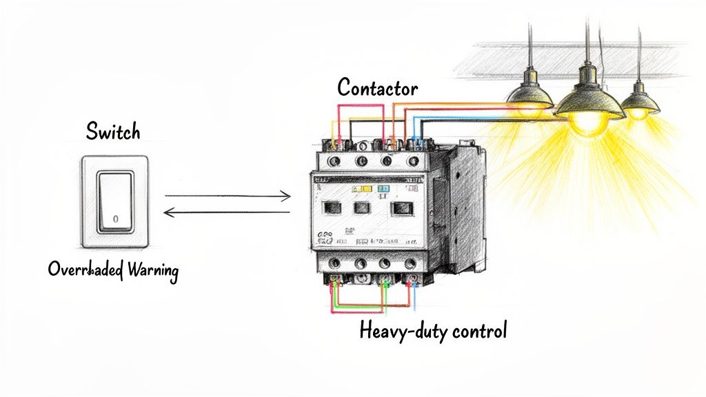
Contactor wiring diagrams for lighting are your roadmap for safely controlling high-power lighting loads. At its core, you're using a beefy electromechanical switch—a contactor—to do the heavy lifting that a normal switch just can't handle. A low-power signal tells the contactor what to do, which in turn manages the massive electrical currents needed for industrial-scale lighting. It’s a simple concept that’s absolutely critical for preventing equipment failure and keeping things safe.
For electricians and engineers in the field, these diagrams are the essential blueprints for getting the job done right.
Why a Contactor is Your System's Unsung Hero
Before we get into the nitty-gritty of schematics, let's talk about why the contactor is the backbone of any serious industrial lighting setup.
Picture a standard light switch in your house. It’s built for a tiny load, maybe a couple of bulbs. Now, try to use that same switch to fire up an entire warehouse full of high-bay LEDs or hungry metal halide fixtures. The huge inrush of current would instantly weld the switch's little internal contacts together. You'd have a melted switch, a dangerous situation, and a permanent failure.
This is exactly the problem contactors are built to solve. They're the go-between. A small, safe control voltage (like 24V DC or 120V AC) energizes an internal electromagnetic coil. This coil acts like a muscle, slamming a set of heavy-duty contacts shut. This allows the high-power, high-amperage electricity to flow directly to the lights without ever touching the delicate control device.
Electrically Held vs. Mechanically Held Contactors
One of the first calls you have to make is choosing between the two main flavors of contactors. This decision really shapes your system's energy use, noise level, and how it behaves.
Electrically Held Contactors: These are the workhorses you’ll see most often. They need a constant low voltage fed to the coil (at terminals A1 and A2) to keep the main power contacts closed. The moment that control power is lost, a spring yanks the contacts open, and the lights go out. It's a fantastic fail-safe feature for a ton of industrial applications.
Mechanically Held Contactors: These guys are a bit different. They use a quick pulse of electricity to one coil to latch the contacts shut and another pulse to a second coil to unlatch them. The big deal here? They use zero power to hold the lights on. This makes them perfect for facilities where every watt counts or where the constant hum from an electrically held coil would be a nuisance.
From years of building UL-listed control panels, I can tell you that electrically held contactors are the go-to for straightforward, fail-safe lighting controls. But for massive operations running 24/7, the energy savings from mechanically held units can really stack up, leading to serious cost reductions over the system's life.
Seeing Them in the Wild
Let's put this into a real-world context. Think about a large manufacturing plant.
You might use an electrically held contactor for the task lighting at a single workstation, controlled by a simple on/off switch. If a control circuit breaker trips, the lights go out immediately, which is a clear signal to personnel that something's wrong.
In that same factory, a mechanically held contactor would be a much smarter pick for the main overhead lighting across the entire production floor, especially if it's running on a timeclock for 12-hour shifts. The timeclock just sends a quick blip of power at the start and end of the shift, slashing the parasitic energy draw from the control system itself.
Getting this fundamental difference down is the first real step toward reading any contactor wiring diagrams lighting schematic with confidence.
Identifying the Core Components of Your Contator Circuit
A rock-solid lighting circuit is built from more than just the contactor. It's an entire system where every part has a critical job. Getting your contactor wiring diagrams lighting schematic right from the start means knowing what each component does and why you're choosing it for your specific industrial setup.
Beyond the contactor, which does the heavy lifting, you've got a whole supporting cast that handles safety, control, and overall function. This includes everything from circuit protection to the devices that actually tell the contactor when to energize.
The Essential Players in Your Circuit
Let's walk through the key pieces you'll find in any professionally built lighting control panel.
The Contactor: This is the high-power switch at the heart of the circuit, built to handle the heavy electrical load from your lights. While it's the star of the show, it's useless without the right support. You can see the physical specs on various [specific contactor models](https://yasutrading.com/products/Contactor LC1D25M7 25A 3-Pole, 220V Coil, AC-3 Duty, Compact Frame) to get a better feel for them. And if you're still fuzzy on the details, check out our guide on the difference between a contactor and a relay.
Circuit Breaker or Fuses: This is your non-negotiable overcurrent protection. Its one job is to protect the wiring and your lighting fixtures from catastrophic short circuits or overloads. A correctly sized breaker is the first line of defense for a safe, code-compliant installation.
Overload Relay (Optional but Recommended): A breaker saves the circuit from big, sudden problems. An overload relay is more subtle—it protects the load itself. It keeps an eye out for smaller, sustained overcurrents that won't trip a breaker but can slowly cook the ballasts or LED drivers in your fixtures.
Control Transformer: In most industrial plants, lighting runs on high voltage like 480V or 277V AC. You absolutely do not want that kind of power running to a pushbutton an operator is touching. A control transformer is the solution, stepping that high voltage down to a much safer control voltage—typically 120V AC or 24V DC.
Control Devices: These are the brains telling the contactor's coil (terminals A1 and A2) when to pull in. This could be as simple as a manual start/stop station or something more complex like a timer, photocell, or networked occupancy sensor.
Choosing the right parts isn't just about volts and amps. In gritty industrial environments, you have to think about the NEMA rating of your enclosure and components. It's all about protecting the gear from dust, moisture, and chemicals. A NEMA 4X rating, for instance, is a must in food processing plants where high-pressure washdowns are part of the daily routine.
The demand for these systems isn't slowing down. The global lighting contactor market was valued at USD 683.7 million back in 2017 and was on track to hit USD 1,111.0 million by 2023. This growth really highlights how critical reliable contactor wiring diagrams lighting solutions are for modern industrial facilities.
Key Component Selection Checklist
Getting the component specs right is make-or-break for any project. Here's a quick cheat sheet to help you plan your next lighting control panel.
Component
Primary Function
Key Selection Criteria (Voltage, Amperage, etc.)
Common Industrial Use Case
Contactor
Switches high-power lighting load
Amperage rating, coil voltage, number of poles (2, 3, or 4)
Controlling banks of high-bay LED fixtures in a warehouse.
Circuit Breaker
Overcurrent and short circuit protection
Amperage rating, interrupting capacity, voltage
Main disconnect and safety for the entire lighting circuit branch.
Control Transformer
Steps down voltage for the control circuit
Primary/secondary voltage, VA rating
Converting 480V AC to 120V AC for a start/stop station.
Timeclock
Automated, scheduled lighting control
Voltage, channel count, battery backup
Scheduling parking lot lights to turn on at dusk and off at dawn.
This checklist should give you a solid foundation for pulling together a bill of materials that works right the first time.
Wiring Schematics for Single-Phase and Three-Phase Systems
Alright, you've got your components picked out. Now for the fun part: wiring it all up. This is where we bring your lighting system to life, and getting the power wiring right from the get-go is everything.
We’ll break down the two main power setups you’re going to run into out in the field: single-phase and three-phase. Each has its own quirks, but the fundamental flow of power—from protection to the final load—is the same across the board. The lessons I've learned building UL-compliant panels come down to this: do it right, do it safely, and make it last.
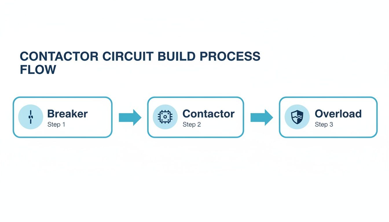
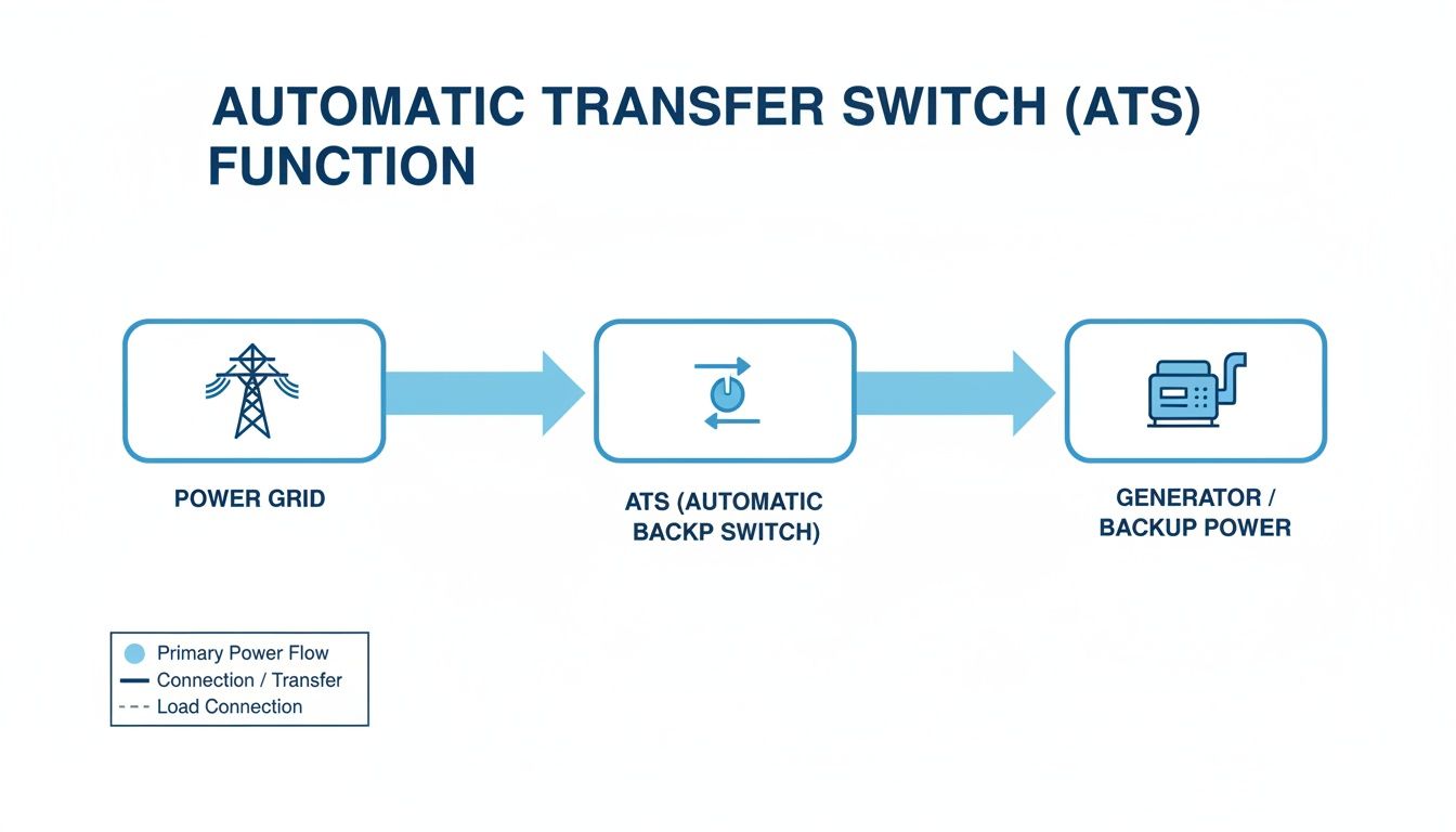
This flowchart shows the basic power path in any contactor circuit. Power flows from the breaker, through the contactor, and finally through the overload protection to the lights.
Keeping this sequence in mind helps you remember that every component has a specific job in controlling and protecting your lighting.
Single-Phase Lighting Contactor Wiring
Single-phase is what you'll find in most smaller commercial spots, workshops, or dedicated zones inside a bigger facility. We're usually talking about 120V or 277V, carried by two wires: a "hot" and a neutral.
When you pull up a contactor wiring diagrams lighting schematic for a single-phase job, the connections are pretty straightforward.
Line (Hot) Conductor: This is the wire coming from your circuit breaker. It lands on the contactor's input terminal, which is almost always labeled L1.
Neutral Conductor: This wire is the return path. It typically runs straight to the lighting load, often connecting through a neutral bus bar in your panel.
Load Conductor: From the contactor's output terminal (T1), a wire goes out to the hot side of your lights.
Ground: This one’s non-negotiable for safety. The equipment ground wire needs to be solidly connected to the metal chassis of the control panel, the contactor's ground lug, and the lighting fixtures.
Pro Tip from the Field: Always, and I mean always, size your wires based on the total amperage draw of your lights, following the National Electrical Code (NEC). Using undersized wire is one of the quickest ways to create a fire hazard. For a standard 20-amp lighting circuit, you should be using 12-gauge copper wire, period.
Picture a small machine shop. You might use a single-pole contactor to switch on all the 120V task lights above the workbenches. The hot wire from a 20A breaker lands on L1. The wire heading to the lights leaves from T1. When the coil gets energized, L1 and T1 connect, and the lights pop on. Simple and effective.
Three-Phase Lighting Contactor Wiring
Step into any large industrial facility, warehouse, or factory, and three-phase power is king. It’s the workhorse that delivers more power more efficiently, perfect for running heavy machinery and huge banks of lights.
Wiring a three-phase contactor means you’re wrangling three separate hot conductors—L1, L2, and L3.
The hookup is just as logical:
Incoming Power (L1, L2, L3): Each of the three hot lines from your three-pole breaker connects to the matching input terminals on the contactor: L1, L2, and L3.
Outgoing Power (T1, T2, T3): Power leaves the contactor from the output terminals—T1, T2, and T3. Each of these lines then feeds a different bank of lights. T1 might handle aisle one, T2 gets aisle two, and T3 powers aisle three.
This isn't just for neatness; it's fundamental to a stable system. The power-side principles are very similar to what you'd see in motor controls, and you can find more examples in this guide on a three-phase motor wiring diagram.
The Importance of Phase Balancing
Here's something I see rookies get wrong all the time: phase balancing. It just means you need to spread your lighting loads as evenly as possible across the three phases.
Let's say you're installing 90 new high-bay LEDs in a warehouse. A bad install would lump them all onto one or two circuits. A professional install wires 30 fixtures to T1, 30 to T2, and the last 30 to T3.
Why does this matter so much?
Prevents Overloads: An unbalanced load makes one phase work way harder than the others. This can cause nuisance trips on the main breaker and puts a ton of stress on that one leg of the system.
Ensures Stable Voltage: A balanced load keeps the voltage steady across all three phases. This means consistent light output and a longer, happier life for your fixture drivers.
Maximizes Efficiency: A balanced three-phase system runs more efficiently, which adds up to real money saved on the power bill over time.
Seriously, failing to balance your phases is an amateur mistake that leads to flickering lights, fried equipment, and a whole lot of frustrating callbacks. Take a few extra minutes during the planning phase to map out your loads. It's the mark of a pro.
Designing Your Lighting Control Circuit Logic
Once the high-power wiring is buttoned up, it's time to tackle the brains of the operation: the control circuit. This is the low-voltage side where you decide how and when your lights actually do their job. A well-thought-out control strategy, laid out in your contactor wiring diagrams lighting schematic, turns a basic on/off switch into an intelligent, automated tool for your facility.
At its core, the control circuit has one simple job: to energize the contactor’s coil (at terminals A1 and A2). But the way it gets that job done can range from a dead-simple manual switch to a complex, sensor-driven network. This is where you bake in real efficiency, safety, and convenience.
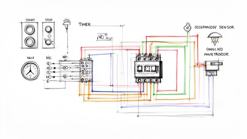
The Classic Start/Stop Pushbutton Circuit
The most fundamental control logic you’ll run into is the standard three-wire start/stop station. It's a classic for a reason—it’s reliable, intuitive, and safe. This setup brings two key players to the field: normally open (NO) and normally closed (NC) contacts.
Start Button (NO): These contacts are open by default. When you push the button, you momentarily close the circuit, sending power to the contactor's coil.
Stop Button (NC): These contacts are closed by default, letting current pass right through. Pushing it breaks the circuit, killing power to the coil and turning off the lights.
So, if the start button is just a momentary press, how do the lights stay on? The magic is in what’s called a "holding" or "latching" circuit. We use a spare normally open auxiliary contact right on the contactor itself, wired in parallel with the start button. The moment the contactor pulls in, that auxiliary contact closes. This creates a new path for electricity, bypassing the now-released start button and keeping the coil energized.
In the real world, the stop button’s NC design is a non-negotiable safety feature. If a wire to the stop button ever breaks or comes loose, the circuit is immediately interrupted, and the system fails to the "off" state. This fail-safe design is a cornerstone of safe industrial controls.
Automating with Timers and Photocells
Manual control is fine, but automation is where you find the real efficiency gains. Bringing timers and photocells into the mix is a common and powerful next step for industrial lighting.
A timeclock lets you schedule lighting around work shifts or facility hours. For example, you could program it to fire up the contactor for your main warehouse lights at 6:00 AM and shut it down at 6:00 PM, Monday through Friday. This one simple change stops you from relying on someone to remember to flip a switch, saving a ton on energy costs over time.
For outdoor security or parking lot lighting, a photocell is your go-to for dusk-to-dawn control. It acts as a light-sensitive switch in your control circuit. When the sun goes down and ambient light drops, the photocell's contacts close, completing the circuit to the contactor coil and turning the lights on. Come sunrise, the contacts open, and the lights switch off automatically.
Adding Intelligence with Occupancy Sensors
For maximum energy savings, nothing beats an occupancy sensor. These devices detect motion or presence in an area and tell the contactor what to do. They're perfect for spaces that see sporadic use, like storage rooms, loading docks, or individual work cells.
Wiring an occupancy sensor into your control circuit means the lights are only burning electricity when someone is actually in the room. In some applications, this can slash lighting energy consumption by up to 60%. The sensor is just an automated switch, closing the control circuit when it detects motion and opening it back up after a set time of inactivity.
This push for smarter controls is a huge market trend. Electrically held lighting contactors, which are a perfect match for these automated systems, have become cost-effective workhorses. The overall lighting contactor market was valued at USD 1.14 billion in 2023 and is set to grow, largely because of this widespread adoption of energy-conscious controls. You can dive deeper into the market dynamics and see how efficiency is shaping the entire industry.
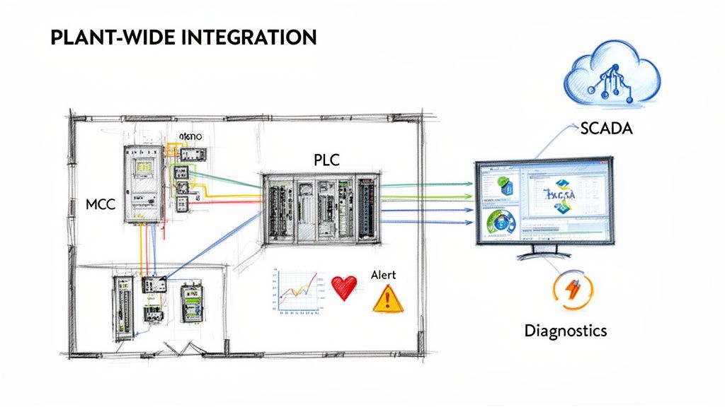
Integrating with PLCs and Building Automation
For the most advanced control, you can tie your lighting contactor into a Programmable Logic Controller (PLC) or a central Building Automation System (BAS). This takes your lighting from a standalone system to a responsive component of your entire facility's operation.
In this kind of setup, the PLC or BAS is the master controller. The system can be programmed with complex logic, like:
Turning on lights in one zone only when a specific machine in that area is running.
Dimming lights during slow periods or when there's enough natural daylight.
Sequencing the startup of different lighting banks to manage inrush current.
The wiring itself is often surprisingly simple. A low-voltage digital output from the PLC (usually 24V DC) gets wired straight to the contactor's coil (assuming you have a matching coil, of course). When the PLC program calls for lights, it sends a signal to that output, energizing the contactor. This level of integration gives you unparalleled control and diagnostic power, making your lighting system truly smart.
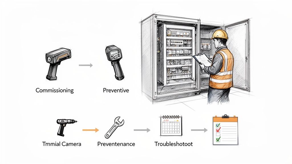
Meeting UL Standards and NEC Safety Codes
Getting the lights to turn on is one thing. Making sure they stay on—safely and reliably—is another challenge entirely. As a UL-certified panel shop, we don't just build systems that work; we build them to protect people and equipment, with safety and compliance baked in from the very first wire.
This isn’t just about checking a box for an inspector. Every single detail in your contactor wiring diagrams lighting schematic has to line up with established safety protocols. That means following the National Electrical Code (NEC) precisely and, for any panel assembly, strictly adhering to UL 508A standards. These aren't just guidelines—they are the law of the land for safe electrical work in the US.
Grounding and Conductor Sizing
You can't overstate the importance of proper grounding. It’s the single most critical safety feature in any electrical system, giving fault current a safe path to travel and preventing a metal enclosure from turning into a lethal shock hazard. Every non-current-carrying metal part, from the contactor frame itself to the fixture housings way out on the floor, needs a rock-solid connection back to the equipment ground.
Just as crucial is choosing the right wire size. The NEC has detailed tables that spell out the minimum wire gauge based on the circuit's amperage and the wire's temperature rating. Using an undersized wire is a recipe for a fire, plain and simple. It will overheat, melt its insulation, and eventually fail catastrophically.
We see one mistake out in the field all the time: installers forget to calculate for voltage drop on long runs. In a big warehouse, the distance from the panel to the last light can easily be hundreds of feet. That resistance adds up, causing voltage to sag, lights to dim, and components to fail prematurely. Always do the math and upsize your conductors to ensure the load gets the voltage it needs.
Component Ratings and Panel Layout
Every single component in your circuit—the breaker, the fuse, the contactor—has a specific voltage and amperage rating stamped on it. You have to select parts rated for the maximum potential load, not just the average. You can't put a contactor rated for 20 amps on a 30-amp circuit, even if the lights only pull 18 amps on a normal day. You build for the worst-case scenario.
How you arrange everything inside the control panel is just as important for safety and long-term reliability.
Power and Control Separation: Keep your high-voltage power wiring physically separate from the low-voltage control wiring. Run them in different wireways or on opposite sides of the enclosure. This prevents electrical noise (EMI) from interfering with your control signals.
Proper Ventilation: Contactors, transformers, and power supplies all generate heat. Your panel needs a way to breathe. Make sure there’s adequate ventilation—or even fans—to keep components from overheating and dying an early death.
Clear Labeling: This is a non-negotiable. Every wire, terminal block, and component must be clearly and permanently labeled. It's a lifesaver during troubleshooting and makes maintenance faster and safer for the next person who has to open that panel.
Following these standards isn't just good practice; it's what the market demands. Commercial applications have always dominated the lighting contactor market, representing a multi-billion-dollar footprint in 2023. This trend is driven by the push for sophisticated, scalable lighting controls that meet tough energy codes. The total market, valued at USD 1.2 billion in 2024, is expected to climb to USD 2.1 billion by 2031.
Ultimately, safety is the top priority on any electrical job, big or small. Even for a simple home project, a guide to a ceiling fan remote wiring diagram with safety tips will stress these same core principles. To get a much deeper look at professional panel building, check out our guide on the best practices for industrial control panel design.
Common Questions About Lighting Contactor Wiring
Even with the best diagrams laid out on a cart, questions always pop up in the field. Let's tackle some of the most frequent challenges and uncertainties we hear from engineers and technicians when they're deep in a lighting control panel. These aren't textbook answers; they come straight from decades of designing, building, and troubleshooting industrial systems.
Can I Use a Motor Contactor for a Lighting Load?
This is probably the most common question we get, and the short answer is: maybe, but you have to be careful. A standard NEMA-rated motor contactor is a beast, built to handle the massive inrush current (inductive load) from a motor kicking on.
Lighting loads are a different animal. Modern LEDs and fluorescents with electronic ballasts have their own high initial inrush, but then they settle into a steady capacitive or resistive load. While a motor contactor is tough, it’s not always the right tool for the job. You can get away with it if it's properly oversized, but you risk premature contact wear or, even worse, the contacts welding themselves shut.
For peace of mind and guaranteed compatibility, stick with a contactor specifically rated for lighting or one with a general-purpose rating that covers your load type.
Why Is My Contactor Buzzing or Humming Loudly?
A slight, steady hum from an electrically held contactor is normal. That's just the sound of the AC electromagnet doing its job. But a loud, angry buzz? That’s a clear cry for help.
Here are the usual suspects:
Low Coil Voltage: If the voltage hitting A1 and A2 is under the coil's rating, the magnet won't have enough muscle to pull the contacts in tight, causing chatter.
Debris or Obstruction: You'd be surprised how a tiny metal shaving or a bit of grit between the magnet faces can keep it from sealing, creating that awful racket.
Wrong Coil for the Job: Slapping a 120V coil into a 24V control circuit (or the other way around) will cause instant problems, from a loud buzz to a fried coil.
Damaged Shading Ring: Inside an AC contactor, a small copper "shading ring" keeps the magnetic field stable. If it's cracked or missing, the contactor will chatter like crazy.
A buzzing contactor isn't just an annoyance; it's a warning sign that failure is right around the corner. That constant vibration will destroy the coil or the contacts. Don't ignore it—troubleshoot it immediately before it leaves you in the dark.
How Do I Choose the Right Coil Voltage?
This one is simple but critical: the coil voltage must match your control circuit voltage. It has nothing to do with the high-voltage power you're switching.
If your control circuit is fed by a transformer that steps 480V down to 120V, you need a contactor with a 120V AC coil. Period.
If you’re working with a modern PLC or automation system, your control logic is likely running on 24V DC. In that case, grab a contactor with a 24V DC coil. Mismatching the coil voltage is one of the fastest ways to let the magic smoke out of a brand-new component. Always double-check your control voltage before you order parts for your contactor wiring diagrams lighting project.
What Does the Auxiliary Contact Do?
Those small contacts on the side or top of the contactor—often labeled 13/14 (NO) or 21/22 (NC)—are the auxiliary contacts. They aren't for the main lighting power. Think of them as the contactor's low-voltage communication system, used exclusively for logic in the control circuit.
Here's what they're typically used for:
Holding Circuit: Like we talked about earlier, a normally open (NO) contact is used to latch the contactor "on" after someone lets go of the start button.
Status Lights: Wire a pilot light through an NO contact, and you've got an instant visual indicator showing when the main lights are on.
Feedback to a PLC: An auxiliary contact can send a signal back to a control system, confirming that the contactor actually pulled in when it was told to.
Essentially, they give the contactor a voice to report its status back to the rest of the control system.
At E & I Sales, we don't just sell components; we provide the expertise to make sure your industrial systems are safe, compliant, and built to last. For help with your next project, from custom UL control panels to system integration, explore our services.
When it comes to high-stakes automation, brushless servo motors are the MVPs. These aren't your run-of-the-mill motors; they're complete, intelligent systems built for jobs where precision, speed, and absolute reliability are the only options. Think of them as the elite athletes of the factory floor.
Why Brushless Servos are the Standard in Modern Automation
If you've ever tried to paint a detailed picture with a thick, clumsy brush, you know the frustration. You can get the general shape, but the fine, critical details are lost. That’s the difference between a standard motor and a brushless servo. The former is great for simple, brute-force tasks, but the latter is the fine-tipped tool that makes modern automation possible.
They are the unseen force guiding a CNC machine with microscopic accuracy, the lightning-fast reflexes of a pick-and-place robot, and the steady hand ensuring every package is sealed perfectly. The move toward servos isn't just a fleeting trend. It’s a direct answer to the relentless demand for higher throughput, perfect quality, and machines that just don't quit. And driving this performance is the cutting edge of digital servo motors and drives.
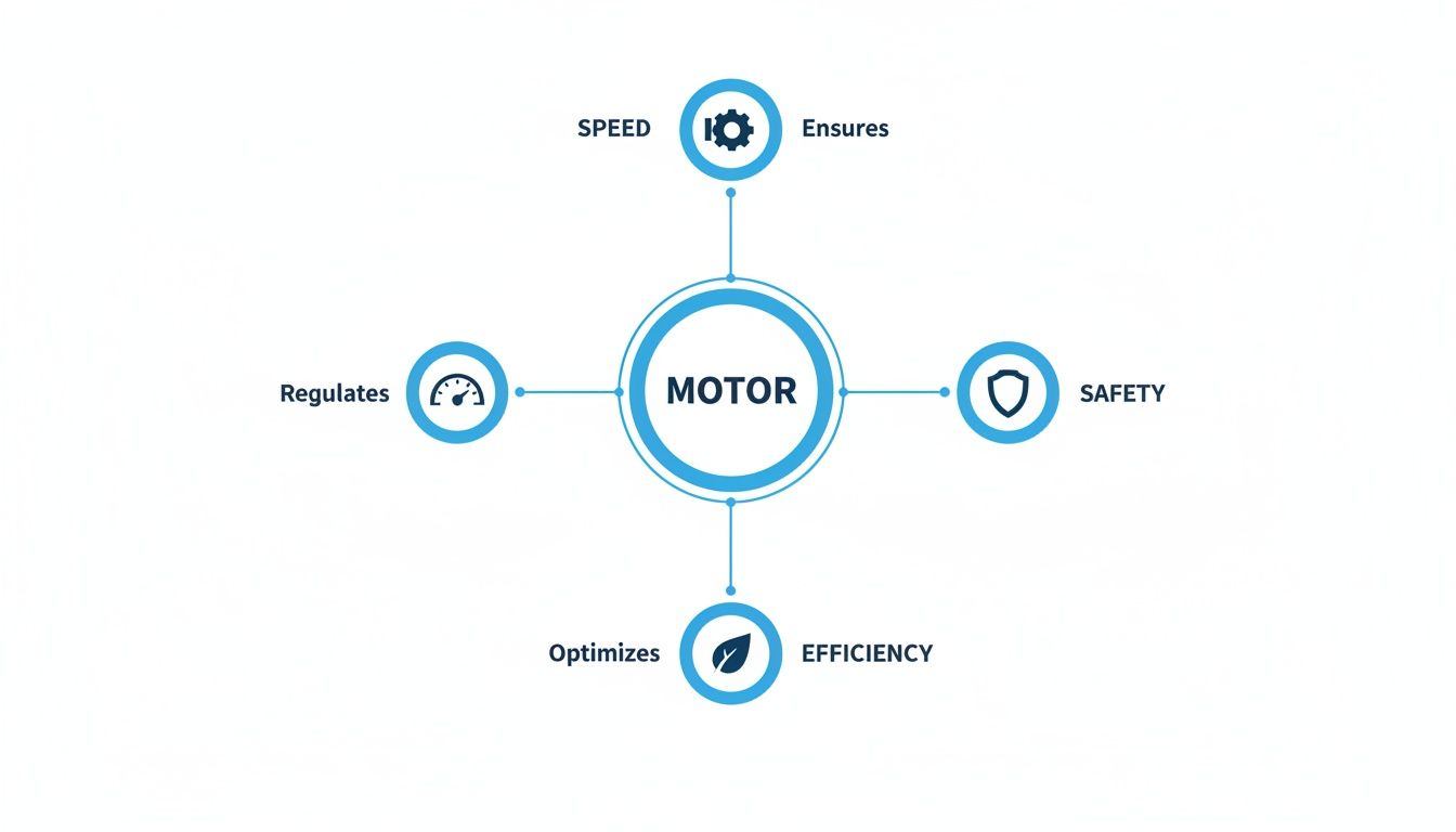
The Three Pillars of Precision
A brushless servo system is really a team of three components working in lock-step to achieve perfect motion.
The Motor: This is the muscle. Its brushless design means there are no physical brushes to wear down, which translates to a much longer, maintenance-free operational life.
The Encoder: This is the system's eyes and ears. It constantly watches the motor’s exact position and speed, feeding that information back in real-time.
The Drive: This is the brain. It takes the feedback from the encoder and instantly sends finely-tuned electrical pulses to the motor, ensuring it never strays from its programmed path.
This constant communication—the feedback loop—is what truly sets a servo apart. The drive is always making tiny, on-the-fly corrections to nail the target position and speed. It's a non-stop process of measure, compare, and correct that guarantees incredible accuracy. This is especially critical in demanding applications, and it's a world away from simpler motor technologies, as we explore in our guide on direct drive motors.
This push for smarter automation is driving huge market growth. The global brushless DC motor market—the heart of these servo systems—was valued at USD 24.01 billion in 2025. It’s projected to nearly double to USD 47.85 billion by 2034. Why? Because eliminating mechanical wear and delivering torque efficiencies that top 90% gives companies a massive competitive edge.
How Brushless Servo Motors Achieve Flawless Control
To really get what makes a brushless servo motor so precise, you can't just think of it as a single component. It's more like a highly coordinated team of specialists working together. This team has three core members, each with a critical job: the motor brings the muscle, the encoder provides the sensory feedback, and the drive is the brain making all the decisions.
Working in perfect sync, they form a closed-loop system that’s constantly checking and correcting itself. This is what allows a servo to execute commands with such incredible accuracy. It's the key difference between a servo and a standard motor. A basic motor gets power and just spins; a brushless servo system is in a constant feedback loop, making thousands of micro-adjustments every second to hit its mark perfectly, every time.
The Powerhouse: The Brushless DC Motor
The motor itself is the brawn of the operation. The genius is in its simplicity—it gets rid of the physical brushes that are the number one point of failure in traditional DC motors. Instead of mechanical brushes making contact to transfer power, it has a permanent magnet rotor spinning inside a stator field with electromagnetic coils.
This "brushless" design means zero friction, no sparking, and no parts to grind down over time. The payoff? You get a motor that runs cooler, is far more efficient (often >90% efficiency), and lasts significantly longer. It's a clean, direct conversion of electricity into pure rotational force.
For anyone in maintenance or plant engineering, this is a huge win. No brushes means fewer PMs on the schedule, far less unexpected downtime, and a lower total cost of ownership over the life of the machine. The thinking is simple: no brushes, no problems.
The Senses: The High-Resolution Encoder
If the motor is the muscle, the encoder is the system’s incredibly precise sense of touch and position. This little device is bolted right onto the motor shaft and acts as a vigilant spotter, constantly tracking the shaft's exact angle, speed, and direction.
Think of it like trying to drive a car with a blindfold on. You can hit the gas, but you have no clue where you are, how fast you're going, or if you're even pointed in the right direction. The encoder is what takes the blindfold off. It sends a constant stream of high-resolution data back to the servo drive, reporting exactly what the motor is doing at any given millisecond.
The Brain: The Intelligent Servo Drive
The servo drive, sometimes called an amplifier, is the sophisticated brain running the whole show. It's constantly running a high-speed calculation to make sure the motion is perfect. The process is straightforward:
Get the Command: The drive receives a target from a PLC or motion controller, something like, "Move to position 1,250 at 300 RPM."
Check the Feedback: It immediately looks at the real-time data streaming in from the encoder to see the motor's actual position and speed.
Correct the Error: The drive instantly calculates the difference—the "error"—between where it should be and where it is. It then sends a precisely adjusted electrical current to the motor's coils to wipe out that error.
This entire sequence happens thousands of times a second. It's this principle, closed-loop control, that allows the system to instantly compensate for changing loads, vibrations, or any other real-world disturbances. The drive's ability to intelligently manage power through electronic commutation ensures the motor is always exactly where it needs to be, doing its job with robotic perfection.
Choosing The Right Motor For Your Application
Picking the right motor technology is one of the most critical calls you'll make in any automation project. This isn't just about grabbing something with enough horsepower; it’s about matching the tool to the specific job at hand. Get it wrong, and you're staring down the barrel of poor performance, unexpected downtime, and costs that spiral out of control.
Think about it this way. A high-speed CNC machine needs to carve intricate patterns into metal with absolute, flawless precision. A desktop 3D printer has to build a prototype layer by layer with dead-on, repeatable steps. And a simple conveyor belt? It just needs to shuttle boxes from point A to point B, no questions asked. Each task demands a totally different flavor of motion control.
This is exactly where the lines between brushless servo motors, stepper motors, and brushed DC motors are drawn. While they all spin, they do so with wildly different levels of precision, speed, and intelligence. The CNC machine is a no-brainer for a brushless servo, with its continuous feedback loop and dynamic response. The printer is a perfect fit for the cost-effective repeatability of a stepper. And that conveyor? The bare-bones simplicity of a brushed DC motor is all it needs.
Head-to-Head Motor Comparison
To make a smart decision, you have to look at how these technologies stack up across the metrics that really matter on the factory floor. We're talking about more than just speed and accuracy. You have to consider the long-game factors like maintenance, operational lifespan, and the total cost of ownership. Each motor type has a unique profile of strengths and weaknesses.
For example, a stepper motor is a fantastic, budget-friendly choice for applications that need high torque at low speeds and solid holding power, like a simple positioning stage. But its performance nosedives at higher speeds, and since it runs open-loop (without feedback), it can lose its position if you overload it. That makes it a non-starter for dynamic, high-speed jobs where a brushless servo truly shines.
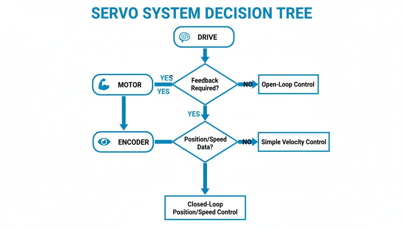
The flowchart below gives you a great high-level view of how the pieces of a servo system fit together, starting with the brains of the operation—the intelligent drive.
As you can see, the drive acts as the brain, commanding the motor (the muscle) based on a constant stream of information from the encoder (the senses). This closed-loop system is the very definition of servo performance.
Evaluating Key Industrial Criteria
When you're writing a spec for a motor, you have to look past the initial price tag and think about the full lifecycle. A brushless servo system might cost more upfront, but its incredible efficiency, practically zero maintenance, and long operational life often lead to a much lower total cost of ownership. This is especially true in demanding, 24/7 operations.
The real art is balancing what you need with what you can afford. A stepper motor might look like a bargain, but the cost of a single missed step in a critical process can easily wipe out any initial savings. A brushless servo is basically performance insurance against those kinds of expensive mistakes.
To really nail this down, let’s get into a detailed comparison and see how these three motor types measure up in the real world. A better grasp of these differences will make it crystal clear why brushless servo motors are the go-to solution for so many modern automation challenges. And if you need to get into the nitty-gritty of the forces involved, you can learn more about how to complete a torque calculation for a motor in our other guide.
Motor Technology Comparison for Industrial Applications
This table breaks down the core differences between brushless servo, stepper, and brushed DC motors. Pay close attention to how factors like lifespan and efficiency impact the long-term value beyond the initial purchase price.
Attribute
Brushless Servo Motor
Stepper Motor
Brushed DC Motor
Precision
Very High. Closed-loop feedback ensures accuracy to fractions of a degree.
High. Good for repeatable steps but can lose position under unexpected load.
Low. Lacks inherent position control; requires external sensors.
Speed Range
Very Wide. Maintains high torque across a broad RPM range.
Low to Medium. Torque drops significantly as speed increases.
Wide. Speed is directly proportional to voltage, but control is basic.
Efficiency
Excellent (>90%). Brushless design minimizes energy loss.
Low to Medium. Draws full current constantly, even when stationary.
Moderate (75-80%). Energy is lost to heat and friction from brushes.
Lifespan
Very Long (20,000+ hours). No brushes to wear out; bearings are the limit.
Long. No brushes, but susceptible to bearing wear.
Limited (1,000-5,000 hours). Brush and commutator wear are primary failure points.
Maintenance
Minimal. No brushes to inspect or replace.
Minimal. Simple mechanical design requires little upkeep.
Regular. Requires inspection and replacement of worn brushes.
Cost
High. Includes motor, encoder, and intelligent drive.
Low. Simple motor and driver combination is very cost-effective.
Very Low. The simplest and cheapest motor technology to implement.
Ultimately, the data speaks for itself. For applications demanding high precision, dynamic performance, and long-term reliability, the brushless servo motor stands in a class of its own.
Mastering Torque, Speed, and Efficiency
This is where the rubber meets the road. Performance is what truly sets brushless servo motor technology apart from everything else. While other motors can spin a shaft, a brushless servo delivers precisely controlled power, speed, and force, making it the go-to for applications where every millisecond and micron is non-negotiable.
To see why these systems dominate high-stakes automation, we need to look at three things: torque, speed, and efficiency.
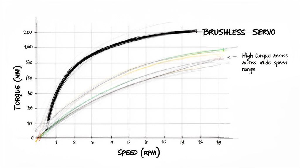
The Torque-Speed Sweet Spot
Think of the relationship between torque and speed as a classic trade-off. With many conventional motors, as you crank up the speed, the available torque (rotational force) just falls off a cliff. It's like a sprinter who bursts out of the blocks but runs out of gas halfway down the track. This can be a massive bottleneck on a production line, forcing you to run machinery slower just to handle heavier parts.
Brushless servos pretty much laugh at this trade-off. They are engineered from the ground up to deliver consistent, high torque across an incredibly wide range of speeds. You can see this clearly on a torque-speed curve; for a brushless servo, it's a long, flat line before it finally starts to taper.
That flat curve is the secret sauce. It means a robotic arm can sling a heavy component around just as forcefully at high speed as it can at a slow crawl. The result? Faster cycle times without ever compromising on power or precision.
Unlocking Serious Energy Efficiency
Efficiency is another area where brushless servo motors are simply in their own league. Since they don't have any physical brushes creating friction, they don't waste energy. It’s an elegant design that converts more electricity directly into useful mechanical work. We’re often talking efficiency ratings of 90% or higher.
That isn't just a number on a spec sheet—it hits the bottom line. A more efficient motor draws less power, which means lower energy bills for the facility, month after month. In an era of rising operational costs and a push for sustainability, that’s a huge win.
The performance gains are substantial. Brushless servos can achieve efficiencies up to 95%, a significant leap over the 75-85% typical for induction motors. This superior efficiency, combined with lifespans exceeding 20,000 hours, makes them an ideal fit for the collaborative robotics sector, where energy-efficiency mandates are driving adoption. Discover more insights about the servo motor market and its growth drivers at Mordor Intelligence.
The Critical Advantage of Running Cool
A direct result of incredible efficiency is fantastic thermal performance. In a motor, wasted energy almost always becomes heat. Since brushless servos waste so little energy, they run significantly cooler than their brushed or even stepper motor cousins.
This cool operation is a game-changer for industrial machinery. Here’s why:
Longer Component Life: Heat is the mortal enemy of electronics and mechanical parts. A cooler motor means bearings, windings, and encoders last longer, which translates to better reliability and less downtime.
Tighter Integration: Because they don’t throw off a ton of heat, you can pack brushless servos into tighter spaces without needing bulky fans or complex cooling systems. This is a massive plus in crowded control cabinets or intricate machine designs where every inch counts.
Improved Safety: Lower operating temperatures reduce the risk of overheating during demanding, non-stop production cycles. This makes the entire machine safer and more stable.
At the end of the day, the exceptional torque, speed, and efficiency of brushless servo motors aren't just technical specs. They are the engine of modern productivity, giving manufacturers the power to build automated systems that are faster, more reliable, and more cost-effective than ever before.
Integrating Brushless Servos Into Your System
Getting a brushless servo system up and running is about much more than just picking a powerful motor. It’s about building a complete, intelligent motion control ecosystem where every part works in perfect concert.
This whole process demands careful planning, from matching the right components to making sure the final assembly meets critical safety and regulatory standards. One wrong move, and you're looking at poor performance and costly delays.
The absolute foundation of a solid system is the relationship between the motor and its drive. Think of it like a high-performance engine and its transmission—one is basically useless without the other. The servo drive has to be matched perfectly to the motor's voltage, current, and feedback specs to actually get the speed and torque you paid for.
Matching Drives and Encoders for Peak Performance
One of the most common mistakes we see is undersizing the drive. This starves the motor of the power it needs under heavy loads, which means you get sluggish, weak performance right when you need it most. On the flip side, an oversized drive is just a waste of money and can make the setup more complicated than it needs to be. The sweet spot is a drive that can comfortably handle the motor’s continuous and peak current demands without going overboard.
The encoder is just as critical. It’s the system's source of truth, constantly telling the drive where the motor shaft is. Its resolution has a direct impact on your final positioning accuracy. For a high-precision CNC machine, you’ll absolutely need a high-resolution absolute encoder. But for a simple pick-and-place robot, a standard incremental encoder will probably do the trick. The key is matching the feedback device to the precision the job demands.
Crucial Takeaway: A servo system is only as strong as its weakest link. A premium motor paired with a mismatched drive or a cheap, low-resolution encoder is a recipe for disappointment. Getting the components paired correctly is the first and most important step toward flawless motion control.
Integrating Safety and Ensuring UL Compliance
Modern automation isn’t just about speed; it's about safety. Safe Torque Off (STO) is a feature that's pretty much non-negotiable these days. STO is a safety function that tells the drive to cut torque to the motor, bringing it to a safe stop without having to kill power to the entire control panel. Integrating STO correctly is fundamental to building machinery that is both highly productive and safe for the people operating it.
This all ties directly into getting a UL-listed control panel. UL certification is a mark of safety and quality that proves the entire assembly was designed and built to strict standards. Everything from component selection to wire sizing and panel layout matters for compliance. If you're building equipment for industrial settings, you have to build with these best practices in mind. You can dig deeper into this in our overview of electric motor control systems.
For the plant maintenance managers and system integrators out there, these details deliver real results. Brushless designs can cut down on heat by 40% and reduce vibration by 60% compared to their brushed counterparts, making them perfect for complex automation hardware. When you source these components through nationwide partnerships, you can even slash project timelines by 15-20% with a single, streamlined commissioning process.
At the end of the day, successful integration is a holistic process. It takes real expertise in both specifying the right components and designing the system as a whole to create a solution that is powerful, safe, and compliant from the get-go.
Where the Rubber Meets the Road: Real-World Applications and Your Procurement Checklist
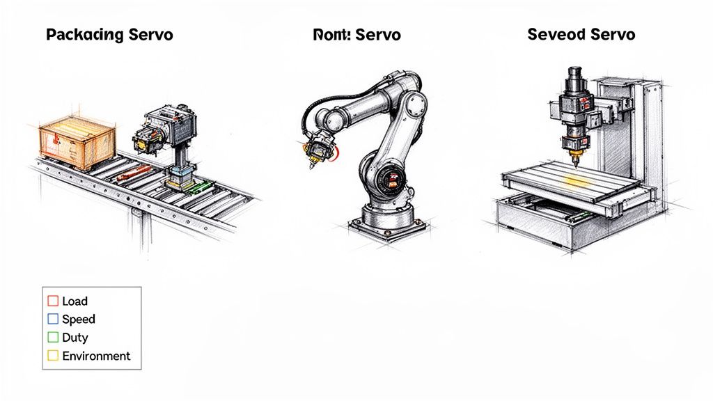
The theory is great, but the real magic of brushless servo motors happens when you see them solving tough problems on the factory floor. These systems are the muscle behind modern automation, providing the blend of speed and pinpoint control that today's production demands. From robotics to packaging, their impact is everywhere.
Think about the blistering pace of an automated packaging line. It’s a brushless servo that lets a cartoning machine fold, fill, and seal thousands of boxes an hour without ever crushing the product. That ability to react instantly to different product weights and sizes is what makes it so indispensable.
In advanced manufacturing, they're what give robotic arms their smooth, almost human-like movement. A servo allows a robot to weld a perfect seam, apply a flawless coat of paint, or assemble tiny components with sub-millimeter accuracy. It’s the same story with CNC machines, where brushless servos guide cutting tools with absolute fidelity, carving complex parts out of solid blocks of steel.
Your Procurement Checklist for Brushless Servos
Getting the specs right on a brushless servo system is one of the most critical parts of any automation project. One wrong move here can spiral into poor performance, frustrating downtime, and blown budgets. Before you even think about calling a vendor, use this checklist to nail down your requirements. It forces you to ask the right questions and ensures you’re buying a solution, not just a motor.
A solid specification process takes the guesswork out of the equation for both your team and your supplier. It's the foundation for a smooth integration.
Remember, you're not just buying a motor. You're sourcing a complete motion control solution. The more detail you put into your initial requirements, the fewer headaches you'll have during design, build, and commissioning.
Here are the key questions you need to have answers for:
What’s the Load? You need to know the mass, inertia, and any friction the motor has to fight against. Is that load consistent, or does it change mid-cycle?
What’s the Motion Profile? Get specific. Map out the exact speeds, acceleration, and deceleration you need. How far does the load move, and how fast does it need to get there?
How Precise Do You Need to Be? Define the positioning accuracy and repeatability the job requires, down to the micron if necessary. This will point you directly to the right kind of encoder.
What's the Duty Cycle? Is this motor running 24/7, or is it doing short, intermittent bursts of work? This is a huge factor in sizing the motor correctly so it doesn't overheat.
What’s the Environment Like? Take note of the ambient temperature, any moisture or dust (which dictates the IP rating), and whether it will be subjected to shock or vibration.
What Are the Power and Control Needs? What input voltage do you have available? And how does this system need to talk to your main PLC or controller? You'll need to know the right communication protocol, like EtherNet/IP or CANopen.
Walking into a conversation with a supplier armed with these answers means you're in control. You'll get a quote for a brushless servo motor system that will perform exactly as you expect, right out of the box.
Brushless Servo Motor FAQs
When you start digging into the details of brushless servo motors, a few practical questions always seem to pop up. Getting straight answers to these common sticking points can clear up a lot of confusion and make specification and maintenance planning much easier. Here are the quick, no-nonsense answers I give engineers and plant managers every day.
What’s the Main Cause of Failure in Brushless Servo Motors?
This is where brushless motors really shine. Unlike their brushed cousins where brush wear is a constant headache, brushless servos are built like tanks. The most common failures almost never have to do with the motor itself, but with the mechanical parts supporting it.
Bearings are the number one culprit. Usually, it's a simple case of improper lubrication, contamination from the plant environment, or just pushing the motor way past its rated load day in and day out. Other things to watch for include:
Encoder Failure: These are sensitive electronics. A good jolt from a machine crash, excessive vibration, or electrical noise can knock one out.
Cable Damage: A frayed or broken cable from poor routing or constant flexing is a classic point of failure that can cause all sorts of intermittent gremlins.
Even with these possibilities, the core motor design is incredibly tough. It’s not uncommon to see them run for well over 20,000 hours in a well-designed system.
Are Brushless Servo Motors More Expensive Than Other Types?
Yes, if you're just looking at the upfront price tag, a full brushless servo system—the motor, encoder, and drive—costs more than a simple stepper or brushed DC motor. But that's not the whole story. You have to think in terms of Total Cost of Ownership (TCO).
The real value of a brushless servo system isn't what you pay for it today, but what it saves you over its entire operational life. That initial cost is an investment in performance and reliability that pays for itself.
Their incredible efficiency means they use less electricity, which adds up on your utility bill. More importantly, the “no-touch” design means you can completely forget about brush inspections and replacements. That’s a huge win for cutting downtime and labor costs. For any demanding application where you can't afford to compromise on precision and speed, a brushless servo delivers performance that other motors just can't touch, making the investment a no-brainer.
Can I Replace a Stepper Motor with a Brushless Servo Motor?
Absolutely. Swapping a stepper for a brushless servo is one of the most common performance upgrades we see, but it's not a simple one-for-one exchange. These two technologies are fundamentally different animals.
A brushless servo demands a closed-loop system. That means you're not just replacing the motor; you have to install the whole package: the servo motor, its high-resolution encoder for feedback, and a dedicated servo drive that can read that feedback and tell the motor what to do. The old stepper motor and its driver have to come out completely.
But the payoff is immediate and significant. You'll get buttery-smooth and quiet operation, much higher speeds without losing torque, pinpoint positional accuracy, and—most importantly—the ability to handle sudden load changes without ever losing its position. That last one is a game-changer if you've ever been frustrated by a stepper stalling out.
For decades, E & I Sales has been the go-to partner for navigating these technical decisions, from picking the right component to integrating a full system. We help OEMs and plant managers design and build automation that just works.
Ready to see what your machine is really capable of? Explore our custom UL control packaging and turnkey integration services at https://eandisales.com.
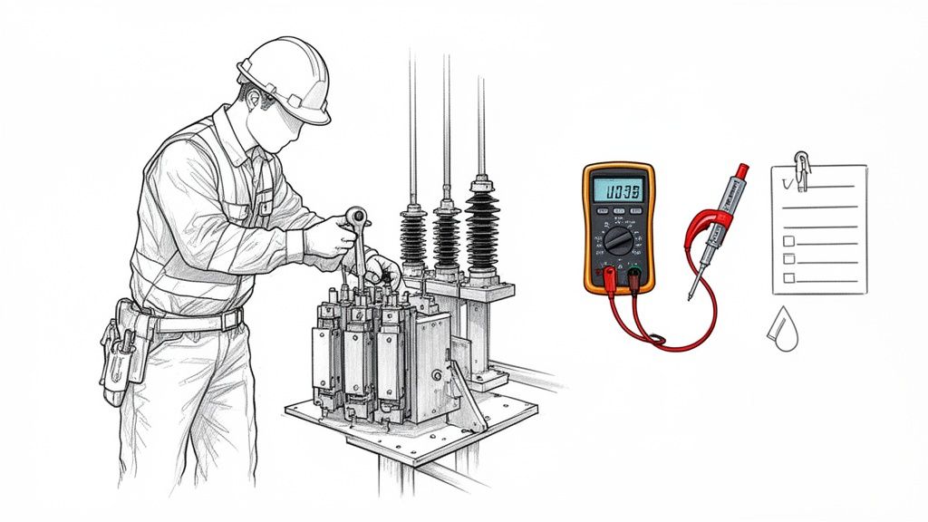
Three-phase monitoring is like a continuous health check for your most critical industrial equipment. It’s all about spotting electrical issues like voltage imbalances or current spikes before they can cause a catastrophic failure, giving you the hard data needed to prevent costly downtime and protect high-value assets.
What Is Three Phase Monitoring and Why It Matters
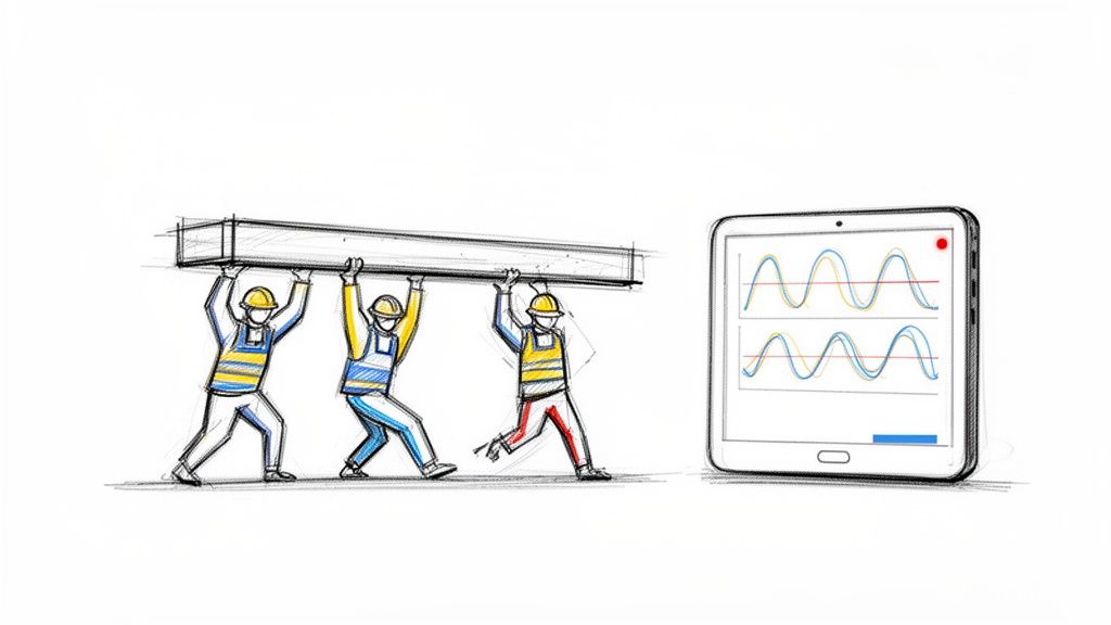
Think about a three-person crew perfectly synchronized, lifting a heavy, expensive piece of machinery. When all three lift with equal force and timing, the load is stable and everything goes smoothly. But what happens if one person stumbles or suddenly loses their grip? The whole operation is at risk. The load becomes unstable, putting immense strain on the other two and risking a disastrous drop.
That’s the perfect way to think about three-phase power. The big motors and pumps that drive your operations depend on three balanced electrical currents—or "phases"—to run efficiently and safely. When those phases are in harmony, your equipment runs like a dream.
The High Cost of an Imbalance
The trouble starts when one phase weakens, surges, or disappears entirely. This condition, known as phase loss or imbalance, has severe and immediate consequences. Your motor is suddenly forced to work much harder under incredible stress, causing it to overheat in a hurry. This kind of thermal stress degrades insulation and can completely destroy windings, leading to a premature and catastrophic failure.
This is why proper three-phase monitoring is so vital for maintaining the health of complex electrical systems. It’s designed to identify these subtle problems long before they escalate into serious equipment damage, acting as an early warning system that gives your team the data they need to step in and fix things.
An unbalanced electrical supply is one of the biggest culprits behind motor failure. Even a small voltage imbalance can dramatically spike a motor's temperature and literally cut its operational lifespan in half, turning a preventable issue into a major capital expense.
Turning Data into Reliability
The real goal of three phase monitoring isn't just about collecting a bunch of data points; it's about turning that data into rock-solid reliability. By keeping a constant watch on the vital signs of your power supply, you can:
Prevent Unplanned Downtime: Catch phase imbalances, voltage sags, and overcurrent conditions before they trip breakers or burn out motors.
Extend Equipment Lifespan: Make sure your motors run well within their specified limits, which drastically reduces wear and tear from electrical stress.
Improve Energy Efficiency: Pinpoint and fix power quality issues that cause equipment to draw more power than needed, helping to lower your operational costs.
In the world of industrial power management, three-phase multifunction monitoring relays are a cornerstone technology. To give you an idea of their importance, the global market for these relays was $1,120.68 million back in 2021 and is projected to climb to $1,438.9 million by 2025. That growth tells you everything you need to know about their vital role in protecting critical assets.
Understanding Your System's Electrical Vitals
To really get a handle on protecting your motors, you need to speak their language. The data from your monitoring system isn't just a bunch of numbers—it's the vital signs of your entire electrical operation. We're going to move past the textbook definitions and get into why each of these metrics is a make-or-break indicator for performance and reliability.
It helps to think of your electrical system like the plumbing in a huge building. The parallels are surprisingly useful and can make some pretty complex electrical ideas click into place. Suddenly, those abstract figures on a screen become real, actionable intelligence.
The Core Duo: Voltage and Current
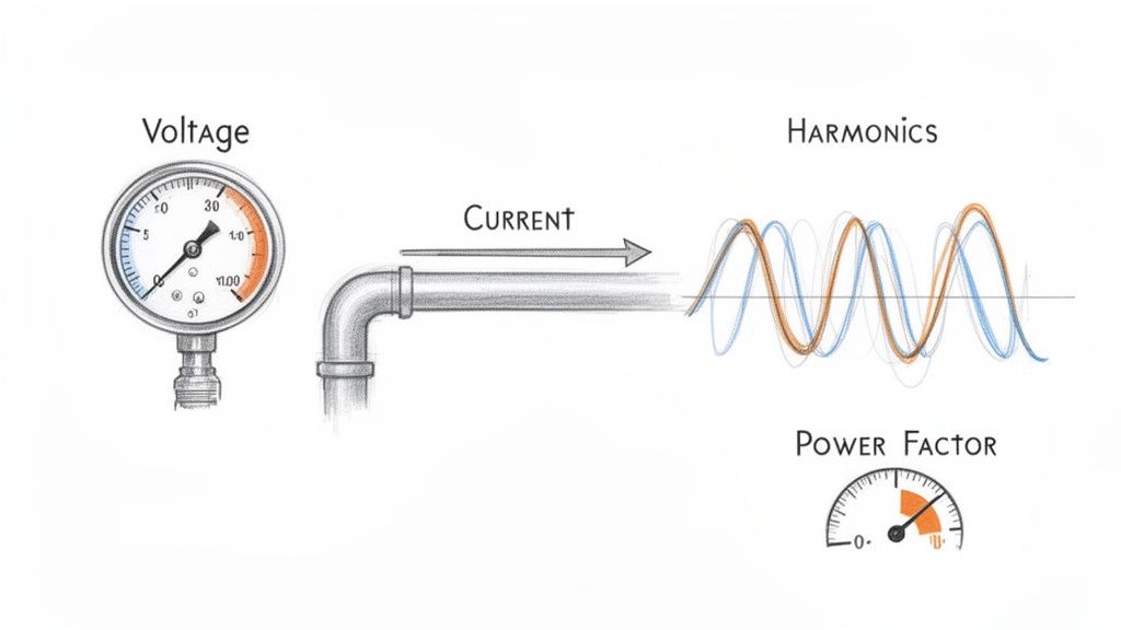
Let's start with the absolute basics: voltage and current. These two are the foundation of everything else.
Voltage is your electrical 'pressure.' Just like water pressure is needed to push water through pipes, voltage is the force pushing electrical energy through the wires to your equipment. If that pressure drops too low (undervoltage), your motor will strain to do its job, causing it to overheat and run inefficiently. On the flip side, if the pressure is too high (overvoltage), you risk frying sensitive components and drastically shortening the motor's life.
Current is the 'flow rate.' Measured in amps, it's the amount of electricity your motor is actually pulling to get the work done. A sudden, sharp spike in current is often the first red flag that a motor is struggling with a mechanical problem, like a bearing starting to seize up or a jam on the conveyor line. Watching the current gives you a live look at the motor's real-world workload.
Keeping a close eye on voltage and current is ground zero for any effective three-phase monitoring plan. These two numbers are the starting point for diagnosing nearly every other electrical headache you might encounter on the factory floor.
Imbalance: The Uneven Workload
This is where the 'three' in three-phase power becomes so important. An imbalance happens when the voltage or current isn't perfectly equal across all three phases. Think of it like a three-person team trying to lift something heavy, but one person is slacking off. The other two have to work way harder to pick up the slack, putting a dangerous amount of strain on them.
For a motor, that uneven load is a death sentence. The imbalance creates what are called negative sequence currents, which actively work against the motor's rotation. This generates a massive amount of waste heat, and that thermal stress is one of the biggest killers of winding insulation, leading directly to costly and premature motor burnouts. A solid grasp of motor control circuit design is crucial for understanding how these imbalances wreak havoc.
Harmonics: The Electrical Pollution
Harmonics are a type of electrical 'pollution,' and a common culprit is modern equipment like Variable Frequency Drives (VFDs). VFDs are fantastic for controlling motor speed and saving energy, but they don't draw power in a nice, smooth sine wave. Instead, they chop it up, creating distortion and 'noise' that gets reflected back into your entire electrical system.
This harmonic distortion is especially brutal on motors and transformers, causing them to vibrate and overheat. It's like feeding your equipment electrical junk food; it'll run, but it’s causing serious long-term damage. This is a huge issue in modern plants, where it's not uncommon for 70% of motor drives to be affected by VFD-induced harmonics, making advanced power quality meters an absolute must-have. You can dive deeper into how to improve your overall electrical power quality.
The numbers don't lie. The market for the very three-phase power quality meters needed to fight these issues was on track to hit $1,252 million back in 2021. This explosive growth is a direct answer to the staggering cost of outages, which hit manufacturers for an estimated $50 billion every year.
Power Factor: Your Efficiency Score
Finally, we have the power factor. This metric, scored on a scale from 0 to 1, is basically your system's efficiency report card. It tells you how effectively your equipment is turning the electricity it receives into actual, useful work.
A low power factor (say, 0.75) means your system is pulling more current from the grid than it's actually using, which is just wasted energy. This not only bloats your utility bills but also puts unnecessary stress on your transformers and wiring. In fact, many utility providers will hit you with hefty penalties for a poor power factor, making it a critical number to watch for financial reasons alone. Consistent three phase monitoring is the only way to keep this vital sign healthy.
To tie this all together, here's a quick-reference table breaking down these critical parameters. Think of it as a cheat sheet for diagnosing the health of your three-phase systems at a glance.
Critical Three Phase Monitoring Parameters and Their Impact
Parameter
What It Measures
Sign of a Problem
Risk of Inaction
Voltage
Electrical 'pressure' in the system.
Sustained levels outside the +/- 10% nominal range (sags or swells).
Equipment damage, overheating, premature failure.
Current
Electrical 'flow rate' consumed by the load.
Sudden, unexplained spikes or consistently high readings.
Overheating, insulation breakdown, imminent motor failure.
Imbalance
The difference in voltage or current between phases.
A deviation of more than 1-2% between any two phases.
Severe motor overheating, drastically reduced lifespan, burnout.
Harmonics
Distortion or 'pollution' on the electrical waveform.
High Total Harmonic Distortion (THD), especially from VFDs.
Overheating of motors/transformers, equipment malfunction.
Power Factor
Efficiency of converting power to useful work.
A value consistently below 0.90.
High energy bills, utility penalties, wasted system capacity.
Understanding what these numbers mean is the first step. By actively monitoring them, you're not just collecting data—you're getting ahead of catastrophic failures, optimizing energy use, and protecting your most valuable assets.
The Hardware You Need for Accurate Monitoring
Knowing what to measure is one thing, but having the right tools for the job is what makes effective three-phase monitoring actually happen. Think of your monitoring system as a small, specialized team. You’ve got the sensors acting as the eyes and ears, the meter as the brain crunching the numbers, and the protective gear that steps in when things get dicey.
Putting this team together correctly is the difference between getting raw data and getting real, actionable intelligence. It's how you spot trouble brewing long before it takes down a critical piece of equipment.
The Eyes and Ears of Your System
First things first: you can't just hook up a multimeter to a 480V industrial circuit. It’s not just impractical; it’s incredibly dangerous. That's where instrument transformers come in. They are the essential sensory organs of your entire setup.
There are two main types you'll be working with:
Current Transformers (CTs): These are your system's 'ears.' A CT is a ring you simply clamp around one of the main power conductors. It doesn't make any direct electrical contact. Instead, it senses the magnetic field generated by the current and scales it down to a safe, low-level signal that a meter can easily read.
Potential Transformers (PTs): These are the 'eyes.' A PT (or voltage transformer) is wired in parallel with the high-voltage line. It does for voltage what a CT does for current—stepping it down from something like 480V to a standardized, safe level like 120V for your meter to analyze.
These two components work in tandem to provide a safe, perfectly scaled-down version of the heavy-duty power flowing through your circuits, feeding reliable information to the brain of the operation.
The Brain of the Operation: Power Meters
All that data from the CTs and PTs is just noise without something to make sense of it. That’s the job of the multifunction power meter—the true brain of any modern monitoring system. These aren't just simple readouts; they're powerful little computers that take the raw signals and instantly calculate everything we care about, from basic voltage and current to tricky stuff like power factor and harmonic distortion.
The market for these devices is exploding, projected to hit $15 billion by 2025, which shows just how critical they've become. In industrial motor control centers, where a simple imbalance can be responsible for 25% of all motor failures, these smart meters are non-negotiable. You can dig into the numbers yourself by reading the full market research on this industrial shift.
A multifunction meter is the nerve center of your monitoring strategy. It translates the complex electrical language of your system into clear, understandable metrics you can actually use to make smart decisions.
Protective Relays and Analyzers
If the meter is the brain, then a protective relay is the system's guardian angel. This device goes a step beyond just monitoring—it takes action. You can program a relay to automatically trip a breaker if it sees a dangerous condition, like a massive overcurrent or a complete phase loss. It’s an automated safety net that can shut down a motor before it self-destructs, reacting far faster than any human ever could.
For those really tricky, intermittent electrical gremlins, you might need to bring in the specialist: a power quality analyzer. While your meter gives you the day-to-day vital signs, an analyzer is like an EKG for your electrical system. It can capture high-speed events and perform a deep-dive analysis of harmonic issues, helping you find the root cause of problems that otherwise seem to appear and disappear at random. Whether you need a standard meter or a full-blown analyzer really just depends on how complex your facility is and how deep you need to go.
Integrating Monitoring into Your Control Panels
Having the right hardware is a great start, but a pile of even the best components doesn't automatically create an intelligent system. The real magic happens when you bring it all together. Integration is where you transform individual devices into a single, cohesive network that gives you clear, actionable data.
Think of it as building the central nervous system for your electrical assets, connecting them all back to your main command center.
This process is about more than just plugging things in. It demands careful planning to ensure everything is safe, the signals are clean, and you’re compliant with standards like the National Electrical Code (NEC). When you get it right, data flows seamlessly from your current transformers and meters directly into your PLC or SCADA system, painting a live picture of your entire operation's electrical health on one central dashboard.
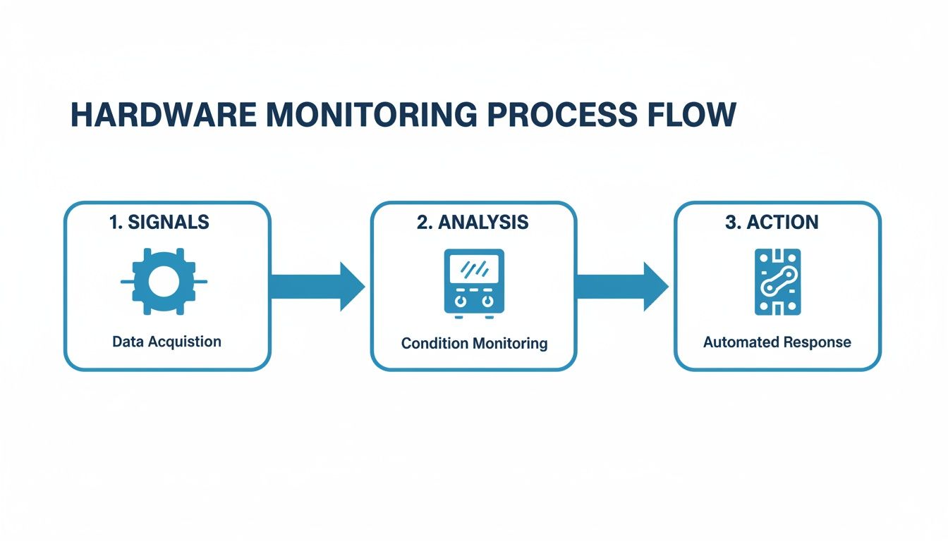
This flowchart shows the fundamental journey of data in a three-phase monitoring system—from a raw signal to an intelligent action.
As you can see, it starts with sensors gathering the raw electrical data. That data is then processed by a meter and finally used to trigger a protective or automated response.
Wiring Best Practices for Signal Integrity
Reliable data starts with clean wiring. Industrial environments are electrically noisy places, full of interference from large motors and VFDs. Protecting the low-voltage signals coming from your monitoring hardware is absolutely critical. A corrupted signal can lead to false alarms or, far worse, a missed fault condition that could have been prevented.
To keep your signals clean, stick to these essential best practices:
Use Shielded Cabling: Always run shielded twisted-pair cables for your communication lines (like Modbus or Ethernet) and for the analog signals from CTs and PTs. This shield is your first line of defense against electromagnetic interference (EMI).
Proper Grounding: Ground the shield at one end only, usually at the control panel or meter side. If you ground both ends, you can create a ground loop, which actually invites noise onto the line and corrupts the very signal you're trying to protect.
Separate Power and Signal Wires: This is a big one. Never run your low-voltage signal wiring in the same conduit or wire tray as high-voltage power cables. Keep them as far apart as possible to prevent the powerful magnetic fields from the power lines from bleeding noise into your sensor wiring.
Connecting to Your PLC and SCADA Systems
Once your hardware is properly wired, the next step is talking to your primary control system, whether that's a Programmable Logic Controller (PLC) or a Supervisory Control and Data Acquisition (SCADA) system. This is what unlocks centralized three phase monitoring and historical data logging.
Most modern meters speak the common industrial languages. The ones you’ll run into most often are:
Modbus RTU: A serial communication protocol that's been the workhorse of industrial automation for decades. It's incredibly reliable and supported by pretty much every PLC and HMI out there.
Modbus TCP/IP: This is the Ethernet version of Modbus, letting your meters connect directly to the facility's network. It’s faster and gives you more flexibility for tying into modern SCADA systems.
EtherNet/IP: Another popular Ethernet-based protocol, especially common in plants that lean heavily on Rockwell Automation/Allen-Bradley PLCs.
The goal here is to map the data registers from the meter to the tags in your PLC or SCADA software. This mapping tells the control system where to look for specific data points—like the voltage on Phase A, the total harmonic distortion, or the power factor—so it can be displayed, logged, and used to trigger alarms.
Proper integration isn't just about seeing what's happening right now; it's about creating a historical record. That data lets you track trends over time, figure out what really happened after a trip, and finally shift from reactive repairs to a data-driven, predictive maintenance strategy.
The Role of UL-Listed Control Panels
While you could piece together a monitoring system yourself, that path is loaded with risks related to safety, compliance, and performance. This is where professionally engineered, UL-listed control panels are worth their weight in gold.
A UL listing (like UL508A for industrial control panels) is an independent stamp of approval certifying that the entire panel assembly—not just the individual parts—meets tough safety and construction standards. To really appreciate the work that goes into this, it's worth exploring the principles behind industrial control panel design.
Going with an expertly engineered and certified panel takes the guesswork and risk out of the equation. It guarantees that all components were chosen to work together perfectly, wired according to best practices, and fully tested before they ever show up at your facility. This approach saves a massive amount of time during commissioning and ensures you get reliable, safe performance from day one.
Translating Monitoring Data into Actionable Fixes
All that raw data streaming from your meters? It's just noise until you know how to read it. The real power of three phase monitoring isn't in collecting data—it's in translating those numbers into smart, decisive action.
Think of this as your field guide for turning a blinking light on a screen into a practical fix on the floor. When you understand the story the data is telling, your team can stop reacting to problems and start preventing them, catching small electrical issues before they have a chance to snowball into catastrophic failures.
Diagnosing a Persistent Voltage Imbalance
A voltage imbalance alert is one of the most common—and destructive—issues you'll run into. If your system flags a persistent difference of more than 1-2% between phases, that’s a direct warning that your motors are under serious thermal stress.
First things first, you have to find where the problem is coming from. Voltage imbalances usually have one of two sources: an issue inside your facility or a problem with the power coming from the utility.
Here’s how to track it down:
Isolate the Source: Start at your main service entrance. Check the voltage before it gets to your distribution panels. If the imbalance is already there, the problem is likely on the utility’s end. Time to give them a call.
Inspect Your Panels: If the power coming in is clean and balanced, the issue is on your side of the meter. The usual suspect? Too many single-phase loads—things like office equipment, lighting, or small heaters—loaded up on one or two phases.
Balance the Loads: This is a job for an electrician. They can help redistribute those single-phase circuits more evenly across your panels. The goal is to get the current draw on each phase as close to equal as possible, which will bring your voltage back into balance and save your three-phase gear.
Responding to Overcurrent and Overload Alerts
An overcurrent alert means a piece of equipment, usually a motor, is pulling more current than its nameplate rating. This is a critical warning. Sustained overcurrent is the number one cause of motor overheating and burnout. The root cause could be mechanical or electrical.
Start by looking at the nature of the overcurrent. Was it a massive, sudden spike, or has it been creeping up over time?
A sudden trip often points to a mechanical jam, a short circuit, or a ground fault. A slowly rising current, however, typically indicates a developing mechanical issue, like a failing bearing that is forcing the motor to work progressively harder.
This distinction is key. If the current spike was instantaneous, you should be inspecting the driven equipment for a physical jam. If the current has been climbing for a while, the motor itself is the likely culprit and needs a mechanical inspection. This is the kind of insight that builds an effective strategy for predictive maintenance for manufacturing operations.
Tackling Low Power Factor and Harmonics
Alarms for low power factor and high harmonic distortion often go hand-in-hand. A poor power factor (anything below 0.90 is a red flag) means you're wasting energy and probably getting hit with utility penalties. High Total Harmonic Distortion (THD), often created by VFDs, pollutes your electrical system and causes sensitive equipment to overheat.
When these alarms pop up, the fix usually involves power quality correction.
For Low Power Factor: The most direct fix is to install power factor correction capacitors. Think of them as a local reservoir of reactive power, improving efficiency and reducing the current your facility has to draw from the grid.
For High Harmonics: If VFDs are creating the electrical noise, installing harmonic filters or line reactors is the solution. These components act like shock absorbers, cleaning up the distortion and protecting everything else on the circuit.
By connecting specific alerts to a logical diagnostic process, your team can act quickly and with confidence. This table is a quick cheat sheet for that initial response.
Measure voltage at the main service entrance to isolate the source.
Overcurrent Trip
Mechanical jam, bearing failure, short circuit.
Check driven equipment for obstructions; analyze current trend data.
Low Power Factor
Inductive loads (motors) without correction.
Install power factor correction capacitors at the motor or panel.
High Harmonics
Prevalent use of Variable Frequency Drives (VFDs).
Install harmonic filters or line reactors to absorb distortion.
Having a simple, repeatable process takes the guesswork out of troubleshooting and turns your monitoring system into a true problem-solving tool.
The Financial Case for Three-Phase Monitoring
While the technical perks of three-phase monitoring are obvious to any engineer, the decision to actually write the check often boils down to one simple question: what’s the payback?
A well-planned monitoring strategy isn’t just another line item in the maintenance budget. It's a powerful financial tool that pays for itself, often many times over, by preventing catastrophic costs and finding hidden efficiencies you never knew you had.
The numbers are staggering. Unscheduled downtime in manufacturing costs the industry an estimated $50 billion every year. A huge chunk of that comes from electrical issues that a good monitoring system is built to see coming a mile away. Let's get out of the clouds and look at a couple of real-world situations where this tech delivers a direct, measurable ROI.
From Unplanned Downtime to Scheduled Maintenance
Picture a big manufacturing plant where a single critical conveyor motor is the heart of the main production line. Without monitoring, the first sign of a problem is usually the motor seizing up, bringing everything to a screeching halt.
This kind of surprise shutdown unleashes a torrent of costs: lost revenue for every minute the line is down, overtime for the scramble to fix it, and maybe even rush shipping for a new motor. A single incident like this can easily balloon into tens or even hundreds of thousands of dollars.
Now, let's hit rewind and play that same scenario back, but this time with a solid three-phase monitoring system installed.
The Problem: The system starts picking up on a small but steady climb in the motor's current draw over a few weeks, along with a slight phase imbalance.
The Monitoring Solution: This data automatically triggers an alert for the maintenance manager. The pattern is a classic tell-tale sign of a mechanical problem, like a bearing starting to go, which is forcing the motor to work harder.
The Financial Return: Instead of a middle-of-the-night failure, the team schedules the motor replacement during a planned shutdown. They completely avoid a line-down disaster, saving an estimated $75,000 in lost production and emergency costs. That one catch just paid for the monitoring system several times over.
Slashing Energy Bills Through Efficiency Gains
Here’s another classic example: a municipal water treatment facility running dozens of huge pumps 24/7. These things are absolute energy hogs, and even tiny inefficiencies add up to massive utility bills over the year.
For many industrial operations, energy is one of the top three operating expenses. Three-phase monitoring provides the granular data needed to transform energy consumption from an uncontrollable overhead into a manageable, optimizable cost center.
The facility decides to install a monitoring system, focusing specifically on power consumption and power factor. The data quickly tells a story: several pumps are running with a poor power factor. This forces the plant to pull more current than it actually needs, and the utility company is hitting them with penalty fees for it.
Armed with this data, the engineers can precisely size and install the right power factor correction capacitors. The result? A 15% reduction in electricity costs for those assets, saving the city over $50,000 a year. The monitoring system just went from being a maintenance tool to a strategic weapon for cutting costs, justifying its initial price tag with a clear and predictable payback.
Got Questions About Three-Phase Monitoring?
Even after you get the basics down, the real questions start popping up when you're on the shop floor, planning an upgrade or trying to solve a problem. Let's tackle some of the most common ones we hear from the field.
What’s the Real Difference Between Single-Phase and Three-Phase Monitoring?
Think of it like this: single-phase monitoring is like watching just one lane on a three-lane highway. It’s perfectly fine for homes or small shops where power comes in on a single, simple waveform. You can see if traffic is flowing, but that’s about it.
Three-phase monitoring, on the other hand, is mission-critical for industrial gear because it watches all three lanes at once. Why does that matter? Because a nasty voltage sag or spike on just one of those "lanes" can absolutely cook an expensive motor. A single-phase system would be completely blind to that kind of imbalance, which is exactly why you need full three-phase protection on your high-value assets.
Can I Bolt This Onto My Existing Equipment?
You bet. In fact, retrofitting is one of the smartest and most common ways to boost your facility's reliability. It usually involves adding a set of current transformers (CTs) and a modern multifunction meter right into an existing motor control panel.
But hold on—this isn't a weekend DIY job. To make sure the install is safe, up to code, and doesn't kill your panel’s UL listing, you have to bring in a certified panel shop. They know how to do the modifications right so the whole system works together without creating a safety hazard or performance nightmare.
Retrofitting older panels with modern monitoring hardware is a killer strategy for cost-effective upgrades. You get all the perks of advanced diagnostics and predictive maintenance without ripping and replacing everything, giving you a fast and obvious return on your investment.
How Does This Actually Help With My Power Bill?
A sharp monitoring system is your secret weapon for cutting down energy costs. It hands you the exact data you need to stop guessing and start making targeted fixes that show up on your utility bill.
Here’s how it works:
Dodge Utility Penalties: By keeping a constant eye on your power factor, you can fix inefficiencies before your utility provider slaps you with costly penalties for poor performance.
Pinpoint Energy Hogs: Detailed current and power data lets you spot oversized or worn-out motors that are just burning cash.
Slash Wasted Heat: Fixing even a small voltage imbalance makes a huge difference. You stop wasting energy as excess heat, which eases the load on your cooling systems and helps your motors live a lot longer.
At E & I Sales, we live and breathe this stuff. We engineer and build the custom UL-listed control panels that make reliable three-phase monitoring a reality. Our solutions give you the clear, actionable data you need to protect your equipment and run a tighter ship. Learn more about our turnkey integration services at eandisales.com.
Medium-Voltage (MV) circuit breakers are the silent workhorses of any serious industrial power system. Their job is simple but absolutely critical: protect incredibly expensive equipment and prevent catastrophic downtime when things go wrong.
Think of them as the ultimate high-speed, automated safety valve for your entire electrical network. When a fault occurs, their one and only mission is to detect it and shut it down—instantly.
The Unsung Heroes of Industrial Power Systems
In any plant, power is the lifeblood. But when a fault happens—maybe a frayed cable shorts to ground or a major piece of equipment fails internally—the surge of electrical energy is enormous. Without a protective device in the way, that surge can vaporize multi-million-dollar assets in a literal flash, cause facility-wide damage, and put your team in serious danger.
This is where MV circuit breakers step in.
They operate in the medium-voltage range, typically from 1kV to 38kV, which is the sweet spot for most manufacturing plants, data centers, and utility distribution systems. They’re engineered to handle the serious power levels found in these environments, standing guard to ensure power flows smoothly day-to-day but acting decisively the second a problem arises.
Why Are MV Circuit Breakers So Important?
Unlike a simple fuse, which is a one-and-done device, a circuit breaker is a reusable, intelligent switch. After a fault is cleared, you can reset it (often remotely) and get operations back online fast. That ability is everything when downtime is measured in thousands of dollars per minute.
For us engineers, integrators, and packagers, knowing these devices inside and out is non-negotiable. It's the foundation of designing a power system that's not just functional, but also safe and resilient.
A properly selected and maintained MV circuit breaker is essential for:
Asset Protection: It’s the last line of defense for your big-ticket items—large motors, generators, and transformers—from destructive overcurrents.
Personnel Safety: By isolating faults in milliseconds, breakers drastically reduce the risk of an arc flash, which can cause life-threatening injuries.
Operational Continuity: A well-designed system ensures only the breaker closest to the fault trips. This isolates the problem locally instead of causing a plant-wide blackout.
System Reliability: They are the cornerstone of any modern electrical grid, whether you're running a traditional factory or integrating renewables like solar and wind.
The Modern Imperative
Let's be honest, the stakes are only getting higher. As industrial processes become more automated and reliant on sensitive electronics, the cost of an unplanned outage is astronomical. At the same time, the grid itself is evolving, with distributed energy resources adding new layers of complexity.
Mastering MV circuit breaker technology isn't just a technical skill anymore—it’s a strategic necessity for keeping any industrial operation competitive and safe. To get a bird's-eye view of how these devices fit into the broader protection landscape, check out this excellent overview on Circuit Breakers. From there, we’ll dive deep into the MV-specific applications that are critical to your work.
How Different MV Circuit Breakers Work
To really get a handle on MV circuit breakers, you have to think about what they’re up against. A fault current isn't just a big number; it's a violent event. It creates an electrical arc—a bolt of plasma hotter than the sun's surface—that desperately wants to keep flowing. The breaker's entire job is to extinguish that arc, and do it in a blink of an eye. The how is what separates the different technologies.
When the breaker's contacts pull apart to stop the current, voltage leaps across the gap, forming that arc. If you just let it sit there, it would melt everything in its path. So, each type of breaker uses a unique medium and a clever bit of physics to de-ionize the plasma, cool the arc, and kill the fault for good.
Vacuum Circuit Breakers (VCBs)
The modern workhorse in the MV world is the vacuum circuit breaker, or VCB. Its design is brilliant in its simplicity. The main contacts are sealed inside a ceramic bottle, called a vacuum interrupter, where nearly all the air has been pumped out.
Think about it like this: a fire can't burn without oxygen. An electrical arc is the same—it needs a medium, like air, to sustain itself. By putting the contacts in a near-perfect vacuum, you’ve essentially starved the arc of its fuel.
When the contacts separate, the only thing that can form an arc is a tiny bit of vaporized metal from the contacts themselves. With almost no gas molecules to ionize, the arc is incredibly easy to extinguish the very next time the AC waveform hits a "current zero." The vacuum's incredible insulating strength then prevents the arc from ever re-igniting.
This simple, elegant mechanism is the VCB’s superpower. It results in an exceptionally long life, almost no maintenance, and quiet, self-contained operation, making it the go-to choice for modern indoor switchgear.
SF6 Circuit Breakers
For years, Sulfur Hexafluoride (SF6) was the king of high-performance arc quenching. These breakers use SF6 gas to smother the arc. It's an electronegative gas, which is a fancy way of saying its molecules are absolute magnets for free electrons.
As the contacts part, a high-pressure blast of SF6 gas floods the arc. The gas molecules immediately soak up the free electrons that keep the arc alive, effectively choking it out. This cools the plasma channel and rapidly restores the insulation between the contacts.
While SF6 is an amazing insulator, it has a serious environmental downside. It’s a greenhouse gas with a global warming potential over 24,000 times that of CO2. Because of this, regulations are tightening, and the industry is shifting hard toward SF6-free alternatives. Still, its performance in high-voltage gear means you’ll see it in the field for years to come.
Air Magnetic Circuit Breakers
This is one of the old-school technologies, but it's a tough and reliable one. Air magnetic breakers interrupt the current right in the open air, but they have a trick up their sleeve. They use powerful magnetic fields to physically move and stretch the arc to death.
Imagine trying to blow out a huge, stubborn candle. Instead of just blowing harder, you could force the flame into a maze of plates that pull it apart and cool it down. That's exactly what these breakers do.
Magnetic Blowout Coils: The massive fault current is routed through coils that generate a powerful magnetic field.
Arc Movement: This field pushes the arc upwards and away from the contacts, like a magnet repelling another.
Arc Chute: The arc is driven into a chamber filled with insulating plates, called an arc chute. This stretches it out, making it longer, thinner, and cooler until it simply can't sustain itself anymore and flickers out.
These breakers are big, loud, and need a lot of maintenance, so you won’t find them in many new installations. But they were built to last, and plenty are still in service in older industrial plants.
Comparing Key MV Breaker Technologies
Choosing the right MV circuit breaker is all about matching the technology to the job. Every design comes with its own set of trade-offs, and what's perfect for a utility substation might be all wrong for a data center.
To make sense of it all, here's a quick comparison of the main players.
Technology Type
Arc Quenching Medium
Key Advantages
Common Applications
Maintenance Needs
Vacuum (VCB)
High Vacuum
Long life, low maintenance, quiet operation, environmentally friendly.
Industrial plants, data centers, commercial buildings, renewable energy.
Very Low
SF6 Gas
Sulfur Hexafluoride Gas
Excellent insulating and arc-quenching properties, compact design.
Robust and simple design, no specialized gas handling required.
Older industrial facilities, traction systems, power generation plants.
High
This breakdown shows why there isn't a single "best" breaker—it's about the right tool for the right application.
This diversity is why MV circuit breakers are such a huge part of the market, holding a dominant 45.53% share of the entire circuit breaker industry. They are the backbone of our industrial and utility grids. The clear trend, as noted by researchers at Fortune Business Insights, is toward the eco-friendly and low-maintenance profile of VCBs, which have become the top choice for new projects.
For most modern medium-voltage jobs, the vacuum circuit breaker is tough to beat on reliability, safety, and total cost of ownership. If you want to get into the nitty-gritty, check out our deep dive into how a vacuum circuit breaker works.
Decoding Critical Ratings and Specifications
Reading the data sheet for an MV circuit breaker can feel like drinking from a firehose. But if you know what to look for, a handful of key numbers tell you everything you need to know about its performance and, more importantly, its safety limits.
These ratings aren't just suggestions; they are the hard-and-fast rules that define the breaker's ability to protect your system. Getting them wrong is a fast track to fried equipment or something much, much worse. Think of these specs as the breaker's DNA—they dictate where it can live, how much load it can carry, and how it will behave when things go sideways.
Voltage Class and Continuous Current
Let's start with the basics. The two most fundamental ratings are the breaker's voltage class and its continuous current. These define its day-to-day operating parameters.
Voltage Class (kV): This is the maximum system voltage the breaker is designed to handle. A 15kV breaker, for instance, is perfectly at home on a 13.8kV system. Its internal insulation and arc-quenching guts are built to handle that level of electrical pressure.
Continuous Current (A): This tells you how much current the breaker can carry, 24/7, without breaking a sweat or overheating. A breaker rated for 1200A can handle that load all day, every day. This value comes down to the physical size and material of its internal conductors.
Matching these two ratings to your system is the first critical filter in your selection process. An undersized current rating means overheating and a shortened lifespan. The wrong voltage class? That's a major safety hazard, full stop. For a deeper look into the calculations, check out our guide on proper circuit breaker sizing.
The Most Important Rating: Interrupting Capacity
Voltage and continuous current are about normal operations. The interrupting rating is about surviving the absolute worst-case scenario. This number, measured in kiloamperes (kA), defines the maximum fault current the breaker can safely extinguish without blowing itself to pieces.
Imagine a dam holding back a river. Its height and width are like the voltage and continuous current ratings—they manage the everyday flow. But the dam's ability to withstand a historic, once-in-a-century flood? That's its interrupting rating.
If a fault unleashes more current than the breaker's interrupting rating, the result is violent and immediate. The immense magnetic forces and arc energy can literally tear the breaker apart, creating a devastating arc flash, spraying molten metal, and starting fires. This is why you can never, ever install a breaker with an interrupting rating lower than the system's available fault current.
Critical Takeaway: A breaker's interrupting rating isn't a performance metric; it's a safety-critical limit. Under-specifying this value doesn't just put the breaker at risk—it jeopardizes the entire switchgear lineup and the lives of anyone nearby.
Understanding Withstand and Operating Duty
Beyond the headline numbers, a few other specs give you crucial insight into how an MV circuit breaker will actually perform in a coordinated system.
Short-Time Withstand Current (kA): This is the amount of fault current a breaker can endure for a very brief, specific time (usually 1-3 seconds) without tripping. Why is this important? It’s all about coordination. This allows a downstream breaker closer to the fault to do its job first, isolating the problem without causing a wider outage. The breaker has to be mechanically tough enough to hold itself together against incredible magnetic forces during this window.
Making Capacity (kA peak): When a breaker closes into an existing fault, the initial current spike can be more than double the sustained fault current. Making capacity specifies the absolute peak current the breaker can safely close against without its contacts welding shut or being blown open.
Operating Duty Cycle: This tells you the sequence of open-and-close operations a breaker can perform in quick succession before it needs a rest. A standard duty cycle might look like O – 0.3s – CO – 15s – CO. This means it can Open, wait 0.3 seconds, do a Close-Open, wait 15 seconds, and then do one more Close-Open. This sequence ensures the arc-quenching medium has enough time to recover between interruptions.
Navigating Global Standards and Protection Coordination
Picking the right MV circuit breaker goes way beyond just matching the basic ratings on a spec sheet. You have to make sure the device speaks the right engineering language for where it's being installed. A breaker’s real-world reliability hinges on two things: following globally recognized standards and being smart enough to trip exactly when—and only when—it’s supposed to.
If you're an OEM or integrator shipping equipment across borders, you’ll constantly run into the two dominant standards bodies: ANSI/IEEE (American National Standards Institute / Institute of Electrical and Electronics Engineers) and IEC (International Electrotechnical Commission). They each have their own philosophy, testing methods, and lingo, which can lead to major headaches if you're not ready for it.
ANSI/IEEE vs. IEC Standards
Think of these standards as two different dialects of the same engineering language. ANSI/IEEE is the go-to in North America, while IEC pretty much runs the show in Europe, Asia, and most other parts of the world. And the differences aren't just for academics—they have a real impact on a breaker's physical design, its ratings, and how it fits into a switchgear assembly.
A perfect example is how they handle interrupting ratings. ANSI often specifies breakers using a symmetrical current value. IEC, on the other hand, uses a mix of symmetrical and asymmetrical values. This subtle difference means you can’t just do a simple, one-to-one comparison between two data sheets. It's an apples-to-oranges situation that can easily trip you up.
In Europe, for instance, sticking to IEC and national standards is absolutely mandatory. That market is on track to hit USD 5.01 billion by 2026, with Germany alone making up USD 1.34 billion of that. This growth is fueled by the massive, interconnected ENTSO-E grid that links over 35 countries, all demanding compliant, reliable circuit protection. For EPC firms, this means every MV breaker has to meet strict local codes while also playing nice with the larger grid.
The Art of Protection Coordination
Standards get you in the door, but true system reliability is born from protection coordination. This is the art and science of making sure the right breaker trips at the right time. The goal is straightforward: isolate a fault as close to its source as possible. You want to prevent a small, localized issue from cascading into a plant-wide blackout.
Picture this: a short circuit happens in a single motor control center. The ideal scenario is that the breaker feeding that specific MCC trips instantly. But if the main plant breaker trips instead? The whole facility goes dark. A minor hiccup just turned into a massive production loss.
Engineers pull this off by programming the protective relays that act as the brains for the breakers. They use Time-Current Curves (TCCs) to map out exactly how each breaker will respond to different levels of overcurrent.
A TCC is basically a breaker's response profile. It plots how long the breaker will wait before tripping at any given current. By carefully layering these curves, engineers create a protective hierarchy, ensuring the device closest to the fault ("downstream") always acts first.
This diagram gives a great high-level look at the core ratings that get programmed and coordinated within a protection scheme.
As you can see, the voltage, continuous current, and interrupting capacity are all distinct but interconnected ratings that define what a breaker can safely handle.
Advanced Coordination Techniques
For more critical or complex systems, engineers have a few more tricks up their sleeve to cut down response times and keep disruptions to a minimum. One of the most effective is Zone Selective Interlocking (ZSI).
With ZSI, the breakers actually talk to each other. When a downstream breaker sees a fault, it sends a "hold off" signal to the upstream breaker, telling it to wait. If that downstream breaker can't clear the fault fast enough, then the upstream one trips as a backup. It's a smart, communicative approach that you can learn more about in our guide to how zone selective interlocking boosts system reliability.
Getting Installation and Maintenance Right
You can specify the most advanced MV circuit breaker on the market, but its real-world performance boils down to two things: how well it was installed and how well it's been maintained. A sloppy installation or years of neglect can turn a critical protective device into your system's weakest link. For the folks in the field and on the plant floor, getting this right isn't just about reliability—it's about safety.
Think of it this way: a proper installation lays the foundation for decades of service. Any shortcuts taken here will absolutely come back to haunt you later.
Nailing the Initial Installation
The path to a long, reliable service life starts the second that breaker hits your loading dock. This isn't just about wrestling it into a cubicle; it's a careful, methodical process where every detail counts.
Handle With Care and Inspect Everything: MV breakers are built tough, but they're not invincible. A drop or a hard jolt can damage sensitive internal components. Before you even think about installation, give it a thorough visual once-over. Look for cracked insulators, bent framing, or any other signs of shipping damage.
Mounting and Alignment: Make sure the switchgear cell is spotless—no dust, debris, or forgotten hardware. As you rack the breaker in, feel for a smooth, positive engagement. You need to be certain the primary stabs and secondary control contacts are perfectly aligned. Even slight misalignment can cause a poor connection that leads to overheating or, worse, a failure of the trip circuit.
The Criticality of Torque: This is where so many installations go wrong. Loose connections create high resistance, which generates heat and can lead to a catastrophic thermal failure. On the flip side, cranking down too hard can strip threads or damage the conductor. Always, always use a calibrated torque wrench and follow the manufacturer's specs to the letter for every single power and control connection.
It’s no exaggeration—one industry study found that improper torqueing was the root cause of over 75% of electrical connection failures. It's a simple mechanical step with massive implications for the safety and integrity of the entire system.
Setting a Rhythm for Preventive Maintenance
Once that breaker is commissioned, you can't just forget about it. A proactive, preventive maintenance (PM) strategy is non-negotiable if you expect it to work when you need it most. This means moving away from a "run-to-failure" mindset and actively hunting for problems before they escalate.
A solid PM program is a mix of simple annual checks and more in-depth testing every few years.
Routine Visual and Mechanical Checks (Annually): With the gear de-energized, open the cubicle and look for tell-tale signs of trouble: dust buildup, corrosion, discoloration from heat, or any hint of moisture. Manually operate the breaker (charge, close, trip) to confirm the mechanism moves freely and doesn't sound "clunky" or strained.
Insulation Resistance Testing ("Meggering"): This classic test is your best friend for verifying the health of the breaker's insulation. By applying a high DC voltage and measuring the resistance to ground, you can spot contamination or moisture ingress long before it leads to a flashover.
Contact Resistance Measurement: You need a clean, low-resistance path through the main contacts when the breaker is closed. Using a digital low-resistance ohmmeter (DLRO) to push a high current through the contacts gives you a precise micro-ohm reading. If you see this number trending upward over the years, it’s a clear sign of contact wear or surface contamination.
Mechanism Lubrication: The grease packed into the operating mechanism from the factory doesn't last forever. It can dry out, harden, or get contaminated with dirt. Follow the OEM's guide for cleaning and re-lubricating the key pivot points and sliding surfaces to prevent a sluggish or failed mechanical operation.
By sticking to these fundamentals for installation and maintenance, you can dramatically extend the life of your MV circuit breakers and ensure they're ready to do their job—protecting your people and your equipment—when that fault finally happens.
Your Essential Procurement Checklist
Choosing the right MV circuit breaker is one of those high-stakes decisions that defines a project’s safety, reliability, and frankly, your bottom line. Get the specs wrong, and you’re looking at costly change orders, dangerous equipment failures, or weeks of unexpected downtime.
Think of this checklist as your pre-flight inspection. It’s a framework to systematically walk through every critical detail before you even think about issuing a purchase order. It’s about moving from a set of requirements to a confident, well-documented decision that gets you the exact equipment your system demands.
Technical and Application Specifications
First things first: you have to nail down the non-negotiable technicals. These are dictated by your electrical system and the environment it lives in. Getting these right is absolutely fundamental.
Voltage Class (kV): What’s the nominal system voltage? Make sure the breaker's rated maximum voltage is a step above that. For a 13.8kV system, you need a 15kV class breaker. No exceptions.
Continuous Current (A): How much full-load current will this breaker see day in and day out without breaking a sweat? Always factor in a healthy margin for future load growth—you’ll thank yourself later.
Interrupting Rating (kA): What’s the absolute worst-case short-circuit current available at the breaker's location? This is a safety-critical number. Understating it is not an option.
Operating Environment: Is this breaker living indoors in a climate-controlled E-house, or is it getting blasted by the elements outdoors? You need to specify the right NEMA or IP rating for the job.
Special Conditions: Don’t forget the curveballs. Are you dealing with high altitudes (which messes with cooling and insulation), corrosive salt spray, or extreme desert heat? These conditions demand special consideration.
Compliance and Integration
Once you have the core specs locked down, you need to think bigger. How does this breaker fit into the rest of your system? This is where you need to put on your system integrator hat.
A well-specified circuit breaker isn't just an isolated component; it's a team player in a larger protection scheme. Its ability to integrate with switchgear, communicate with relays, and comply with regional standards is just as important as its standalone ratings.
The demand for reliable medium voltage gear is exploding, with the market projected to hit USD 11.99 billion by 2030. This growth is fueled by everything from renewable energy tie-ins to massive industrial expansions. For partners like us at E & I Sales who work closely with integrators and packagers, making sure every component plays nice in the sandbox is what we do. You can get more market insights from ResearchAndMarkets.com.
Lifecycle and Commercial Factors
Finally, step back from the upfront price tag and think about the total cost of ownership. This breaker is a long-term asset, probably with a 20- to 30-year lifespan. Thinking about support and parts now will save you a world of hurt down the road.
Standards Compliance: Does the project spec call for ANSI/IEEE (the standard in North America) or IEC (common everywhere else)? They are not interchangeable.
Switchgear Compatibility: Is this a brand-new installation or a retrofit into existing gear? For a retrofit, you have to be meticulous. The breaker’s physical dimensions, racking mechanism, and secondary control connections must be a perfect match for the old cubicle.
Manufacturer Support: What kind of technical backup, documentation, and warranty are you getting? Is there someone you can actually call when you’re in a jam?
Spare Parts Availability: How quickly can you get your hands on critical spares like trip coils, charging motors, or even a new vacuum interrupter? A long lead time on a simple part can turn a minor issue into days of costly downtime.
Common Questions About MV Circuit Breakers
When you're responsible for critical power assets, you're bound to have some practical questions. Whether you're an engineer or a facility manager, getting straight answers is the first step toward making smart calls on safety, budget, and the long-term health of your MV circuit breakers.
Lifespan and Retrofit Decisions
One of the first questions I always hear is, "How long will this thing actually last?" A modern vacuum circuit breaker is typically built for a service life of 20 to 30 years, or a set number of mechanical operations. But the decision to replace or retrofit isn't just about what the calendar says.
You should seriously start thinking about a retrofit when:
You're dealing with an old, obsolete model where finding spare parts has become a treasure hunt.
Your maintenance costs and downtime are creeping up year after year.
The system has grown, and you need to upgrade the breaker's interrupting capacity to keep up.
You're looking to add modern safety features like remote racking or better arc flash mitigation.
New Versus Reconditioned Breakers
The classic dilemma: new or reconditioned? This one usually boils down to a trade-off between cost, lead time, and how much risk you're willing to accept. A properly reconditioned unit can be a great, cost-effective fix, especially for a like-for-like replacement in existing switchgear. Plus, you can often get it much faster.
But—and this is a big but—you have to be certain the reconditioning was done by a reputable shop that follows certified processes. A new breaker, on the other hand, gives you the latest tech, a full manufacturer's warranty, and zero operational history to worry about. For critical new installations, it's almost always the right choice.
When it comes to reconditioned gear, traceability is everything. If you don't have complete documentation of the tests performed and the parts that were replaced, you can't have confidence in its ability to protect your system.
Critical Safety Procedures
Finally, let's talk about what matters most: safety. The question "What are the most critical safety procedures for working on MV switchgear?" should be on everyone's mind. There are a few non-negotiables.
Lockout/Tagout (LOTO): This is ground zero. Always, always verify the equipment is fully de-energized and locked out so it can't be switched back on by mistake.
Arc Flash Hazard Awareness: You need to know the numbers. Understand the specific incident energy levels and approach boundaries for the gear you're working on.
Proper PPE: Don't guess. Wear the correct arc-rated personal protective equipment for the calculated hazard level.
At E & I Sales, we field these questions every day, helping engineers and integrators find the right MV protection for their projects. We’ve got the expertise you need to select, install, and maintain your equipment with confidence. Explore our full range of motor control and power distribution solutions at https://eandisales.com.
At its most basic, an electric motor control system is the collection of hardware and software that tells a motor what to do. Think of it as the brains and nervous system that turns raw electrical power into precise, controlled work. It dictates everything from when a motor kicks on to how fast it spins.
The Brains Behind the Brawn
Electric motors are the undisputed workhorses of industry. In fact, they’re responsible for over 40% of global electricity consumption. But on their own, they're just brute force—little more than a simple on/off switch. A motor control system is what refines that raw power, giving it purpose, intelligence, and a crucial layer of safety. It's the conductor of an industrial orchestra, ensuring every motor plays its part perfectly.
Picture a massive conveyor system in a distribution center. Without a control system, every motor would slam on at once with a jarring jolt, which is a great way to damage products and put immense stress on the machinery. They'd also run at a single, constant speed, guzzling energy even when the workload is light.
Why Control Is Non-Negotiable
Proper motor control brings order to this potential chaos. Instead of a violent, abrupt start, a soft starter can gently ramp up the conveyor’s speed, saving the belts and gearboxes from unnecessary wear and tear. Even better, a Variable Frequency Drive (VFD) can adjust the speed based on the actual volume of packages, which can slash energy costs.
A well-designed electric motor control system does more than just start and stop a motor; it optimizes performance, protects expensive assets, and ensures the safety of personnel. It's the critical link between raw power and productive output.
This control goes way beyond just speed. These systems are absolutely essential for:
Safety and Protection: They constantly monitor for overloads, short circuits, and overheating, ready to automatically shut down the motor before a catastrophic failure can happen.
Operational Precision: For things like CNC machining or robotics, they deliver the exact speed and torque needed to perform incredibly intricate tasks with repeatable accuracy.
Energy Efficiency: By matching the motor's output to the real-time load demand, control systems can cut electricity use by up to 50% in some applications.
Ultimately, these systems are what transform a simple motor from a dumb component into an intelligent, responsive, and efficient part of a much larger automated process.
Understanding The Core Components
To really get a handle on electric motor control systems, you need to peek inside the control panel. Think of it like the engine bay of a car—it's a collection of specialized parts all working together to turn a simple command into controlled, powerful motion. Each component has a specific job, whether it’s distributing power or fine-tuning speed with incredible precision.
Let’s break down the essential hardware that keeps modern industrial operations running. Getting to know these core elements is the first real step toward designing, maintaining, and getting the most out of any motor-driven process.
The visual below shows how a control system juggles a motor's three primary functions: speed, safety, and efficiency.
As you can see, motor control isn't just one single action. It's a balanced strategy to regulate performance while protecting the equipment and keeping energy costs down.
The Command Hub: Motor Control Centers
At the heart of many industrial facilities, you'll find the Motor Control Center (MCC). An MCC is the central nervous system for all the motors in a plant or a specific area. It consolidates starters, protective devices, and control wiring into a single, organized enclosure. Instead of having dozens of separate control boxes scattered across the floor, an MCC gives you one place for control and maintenance.
This centralization is a massive win for both safety and efficiency. It’s no surprise the global market for MCCs is growing so quickly—it's expected to jump from USD 6.73 billion in 2026 to a forecasted USD 11.94 billion by 2035. This growth is a direct result of the automation boom in industries where experts like E & I Sales deliver engineered UL panels and integrated motor control systems.
The Gatekeepers: Motor Starters
The most fundamental piece of the puzzle is the motor starter. Its main job is simple but absolutely critical: to safely energize and de-energize a motor. It acts as a gatekeeper, connecting the motor to the power source and—just as importantly—disconnecting it during an overload or fault to prevent costly damage.
There are a few different kinds of starters, but they all rely on two key parts:
Contactor: This is an electrically-operated switch that physically opens and closes the power circuit to the motor. You can think of it as the muscle of the starter.
Overload Relay: A smart protective device that senses when the motor is drawing too much current. It signals the contactor to open the circuit and shut the motor down before it can overheat.
When you're digging into control system hardware, it’s also important to understand the components they're controlling, like the various three and single phase electric motors that pair with different starter technologies.
The Accelerator: Variable Frequency Drives
If a starter is a basic on/off switch, then a Variable Frequency Drive (VFD) is the system's accelerator pedal. A VFD gives you precise, continuous control over a motor's speed by adjusting the frequency of the electrical power it receives. This capability is a total game-changer for both process control and energy savings.
For example, on a pump or fan, a VFD can slow the motor down when demand is low instead of just running it at full blast all the time. That small adjustment can slash energy consumption by 50% or more, delivering a quick return on investment. If you want to dive deeper into how they work, check out our guide on the basics of Variable Frequency Drives.
A VFD transforms a fixed-speed motor into a variable-speed asset. This allows operations to perfectly match motor output to process demand, eliminating wasted energy and enabling a level of precision that a simple starter cannot achieve.
The Shock Absorber: Soft Starters
So, what if you don't need full speed control but want to avoid the mechanical shock of a motor slamming on at full power? That's where a soft starter comes into play. It provides a smooth, gradual ramp-up to full speed, acting like a shock absorber for both your mechanical and electrical systems.
A soft starter gently increases the voltage to the motor during startup. This reduces the massive inrush of current and lessens the physical jolt on belts, gears, and couplings. This is especially useful for equipment like conveyor belts or large pumps, where an abrupt start can cause serious wear and tear over time. By managing only the startup and shutdown, a soft starter offers a cost-effective way to extend equipment life without the full feature set (and cost) of a VFD.
The table below breaks down the key differences to help you decide which technology fits your needs.
Motor Starter Technology Comparison
Control Method
Primary Function
Best Application
Key Benefit
Direct-On-Line (DOL) Starter
On/off control with overload protection.
Simple, fixed-speed applications like small pumps or fans where start-up torque isn't an issue.
Simple, reliable, and low-cost.
Soft Starter
Ramps motor voltage up/down for a smooth start and stop.
Conveyors, large fans, and pumps where reducing mechanical stress is the main goal.
Extends equipment life and reduces electrical strain during startup.
Variable Frequency Drive (VFD)
Full control over motor speed and torque at all times.
Complex processes requiring precise speed control, like HVAC systems, mixers, or machine tools.
Maximum energy efficiency and ultimate process control.
Ultimately, choosing between a starter, soft starter, or VFD comes down to what your application truly demands. Do you need simple on/off, a gentle start, or complete control over the entire speed range? Answering that question is the key.
How to Design the Right Control System
Choosing the right electric motor control system isn’t like picking a part off a shelf. It’s more like drafting a blueprint for your plant's long-term success. A well-designed system goes far beyond matching horsepower ratings—it’s a strategic decision that touches everything from operational reliability and energy bills to employee safety.
The goal here is to build a solution that nails today's demands while being tough enough for whatever you throw at it tomorrow. That whole process starts with a serious look at the application itself. Before you even think about a single component, you have to understand the job the motor is being asked to do. Getting this right from the start saves you from costly headaches down the road.
Analyzing Your Application and Load
First things first: you need to get intimately familiar with the motor's workload, or what we call its load characteristics. Not all loads are created equal, and this analysis is what dictates the type of control you'll need.
Think of it like choosing an engine for a vehicle. A sports car and a dump truck both have engines, but they’re engineered for completely different jobs. You wouldn't put a Ferrari engine in a dump truck and expect it to haul gravel effectively.
Ask yourself these critical questions about your application:
What's the torque demand? Does the load require a massive kick of starting torque, like a fully loaded conveyor belt? Or does the torque demand ramp up with speed, like with a centrifugal pump?
Do I need speed control? Is the process something that needs to run at different speeds, or is a simple on/off, fixed-speed operation good enough?
How often will it start and stop? A motor that cycles hundreds of times an hour needs a much different control strategy than one that runs continuously for days on end.
Answering these questions honestly prevents you from over-engineering with an expensive VFD when a simple starter would do the trick, or under-engineering a system that’s just going to burn out under pressure.
Defining Operational and Environmental Needs
Once you’ve got a handle on the load, the next step is to map out the operational requirements and the environment the system will live in. This is where you translate the real-world physical demands into concrete electrical and mechanical specs.
You’ll want to consider these factors:
Speed and Torque Control Precision: How tight does the speed control need to be? A simple exhaust fan might be fine with a 5% variance, but a CNC machine or a robotic arm could require precision within a fraction of a percent.
Stopping Method: Does the motor need to coast to a stop, brake hard (dynamic braking), or hold its position firmly once it’s stopped?
Environmental Conditions: Where is this control panel going to live? A hot, dusty factory? A corrosive chemical processing area? Or a clean, climate-controlled room? The enclosure rating (like NEMA 12 or 4X) has to match the environment to protect the sensitive electronics inside.
Ignoring the operating environment is a common—and expensive—mistake. A control panel built for an office setting won't last long on a factory floor exposed to washdowns and metal dust. That's a direct path to premature failure and unplanned downtime.
Proper system design isn't just about day-one performance; it's about endurance. Factoring in environmental stressors and operational demands ensures your investment is protected and your process stays reliable for years.
The push for smarter, more robust motor controllers is accelerating, driven by everything from industrial automation to the EV revolution. The global market was valued at USD 37.99 billion in 2026 and is projected to skyrocket to USD 181.29 billion by 2035, growing at an incredible 18.8% CAGR.
Ensuring Compliance and Future-Proofing
Finally, a truly great design has to meet safety standards and be easy to maintain for years to come. This is where compliance and good documentation become absolutely non-negotiable.
UL 508A certification for industrial control panels is the gold standard here. It’s a sign that the panel has been designed and built to meet strict, nationally recognized safety standards. This isn't just a sticker on a box; it’s peace of mind for inspectors, insurers, and your own team that the system is safe to operate.
Just as critical is solid documentation. This should always include:
Electrical Schematics: The detailed wiring diagrams that show how every single component is connected.
Bill of Materials (BOM): A complete parts list, including manufacturer and model numbers.
Panel Layout Drawings: A visual map showing the physical arrangement of components inside the cabinet.
This packet of documents is your roadmap for any future troubleshooting, maintenance, or upgrades. Without it, a simple component replacement can turn into a painful, time-consuming investigation.
By centralizing components in a well-documented assembly like a Motor Control Center, you make managing and upgrading your systems way easier. For a deeper dive, check out our guide on what a Motor Control Center is and see how it can streamline your operations.
Integrating Controls with Plant-Wide Automation
An electric motor control system is powerful on its own, but its real value is unlocked when it stops being an isolated island of technology. Modern industrial plants thrive on data and connectivity. Tying your motor controls into the bigger automation network is what turns a bunch of individual components into a single, intelligent system that works together.
Think of it this way: a standalone motor starter is like a single musician playing an instrument. They might be skilled, but they have no idea what the rest of the orchestra is doing. Integrating that starter into a Programmable Logic Controller (PLC) network is like giving the musician a headset to hear the conductor and the whole symphony. Suddenly, timing is perfect and everything is in harmony.
This integration connects your motors to the facility's central brain, creating a single source of truth for your entire process. It’s how you get to the next level of efficiency, visibility, and control.
Connecting to PLCs and SCADA Systems
The most common way to do this is by linking your Motor Control Centers (MCCs) and Variable Frequency Drives (VFDs) straight to a PLC. This connection usually happens over standard industrial communication protocols.
EtherNet/IP: This is a popular one because it uses standard Ethernet technology, so most IT and engineering teams are already comfortable with it.
Modbus TCP/IP: An open protocol known for being simple and reliable. You see it a lot when connecting all sorts of different industrial electronics.
PROFIBUS/PROFINET: A really robust standard, especially common in manufacturing and process automation, particularly in facilities running Siemens gear.
Once they're connected, the PLC can send start/stop commands, tell a VFD what speed to run at, and—most importantly—get a constant stream of data back from the motor controls. That information usually gets displayed on a Supervisory Control and Data Acquisition (SCADA) system, giving operators a live dashboard of the entire plant's health.
The Power of Diagnostic Data
This is where the real magic happens. A modern "smart" MCC or VFD does a lot more than just report if it's on or off. It feeds back a ton of diagnostic info that you can use to spot trouble and prevent failures before they bring a line down.
By integrating motor controls with automation platforms, you shift from a reactive maintenance model ("fix it when it breaks") to a proactive, predictive one ("fix it before it fails"). This single change can drastically reduce unplanned downtime and maintenance costs.
Instead of guessing, your team gets hard data on things like:
Current Draw: Is a motor working harder than it should? That could point to a mechanical problem, like a bearing that’s about to fail.
Operating Temperature: A motor running hot might mean a ventilation issue or that a winding failure is on the horizon.
Run-Time Hours: You can schedule maintenance based on how much a motor has actually been used, not just based on a date on the calendar.
Fault Codes: When something does trip, you get a specific code explaining why. This lets technicians find the root cause in minutes instead of hours.
For facilities in logistics and manufacturing, this data-driven approach is essential. It's the foundation for more advanced systems, like fully integrated Automated Storage And Retrieval Systems (ASRS), which depend on this level of connectivity to work.
The demand for these integrated systems is plain to see in the market's growth. The global electric motor market was valued at USD 212.96 billion in 2025 and is projected to hit USD 405.67 billion by 2033. A huge part of that growth is driven by the push for smarter automation and better efficiency. It really just highlights how critical intelligent motor control has become for any operation trying to stay competitive.
Best Practices for Maintenance and Troubleshooting
Getting a state-of-the-art electric motor control system installed is really just the starting line. If you want to get the most out of that investment, you need a solid plan to keep it running reliably for its entire lifespan. This means ditching the old "fix it when it breaks" mentality and embracing a proactive strategy for commissioning, maintenance, and troubleshooting.
A smart approach to the system's lifecycle does more than just prevent headaches. It minimizes costly unplanned downtime, extends the life of your most critical components, and keeps your whole operation humming at peak efficiency. It turns your control panels from mysterious black boxes into predictable, manageable assets. This journey begins the second the installation is finished, starting with a meticulous commissioning process.
The Commissioning Checklist: Your Guarantee for a Smooth Start
Think of commissioning as a systematic shakedown of your new system. It's the process of verifying that everything was installed correctly and performs exactly as designed before you put it into full production. Skipping steps here is a recipe for disaster down the road. A comprehensive commissioning plan is your final, non-negotiable quality check.
Your process should always hit these fundamental stages:
Pre-Power Checks: Before a single volt goes through the system, get hands-on. Physically confirm that all the wiring matches the electrical schematics. Check that every terminal connection is torqued to the manufacturer's spec. Make absolutely sure all grounding and bonding is buttoned up correctly. This is your best and easiest chance to catch simple mistakes that could cause major damage.
Initial Power-Up and Configuration: Once the physical checks are done, it's time to energize the system. Go through it methodically—verify control power, check input voltages, and carefully program the essential parameters into devices like VFDs and overload relays. This includes inputting motor nameplate data and dialing in the right protection settings.
Performance and Safety Validation: With the system live, you need to test its functionality under controlled conditions. "Bump" the motors to confirm they're spinning in the right direction. Test every I/O signal to make sure it's communicating correctly. Critically, verify that all safety circuits, especially emergency stops, function flawlessly. Finally, run the system through its operational sequences to ensure it meets all performance requirements.
Building a Proactive Preventive Maintenance Schedule
Once your system is up and running, the focus shifts to preventive maintenance (PM). A good PM schedule is all about catching small issues before they snowball into major, production-stopping failures. It’s the difference between a scheduled check-up and emergency surgery.
Preventive maintenance is the single most cost-effective strategy for maximizing the reliability and lifespan of electric motor control systems. It turns maintenance from an unpredictable expense into a manageable operational cost.
Your PM schedule should be built around routine inspections and data collection, focusing on the most common points of failure. Key activities should include:
Thermal Imaging: Use an infrared camera to scan your control panels. You're looking for hot spots on connections, contactors, and circuit breakers. An unusually high temperature is a classic early warning sign of a loose connection or a component on its way out.
Connection Integrity: Periodically re-torque all your power and control wire terminations. The constant vibration and temperature swings in an industrial plant can cause connections to loosen over time, creating resistance and dangerous heat.
Environmental Cleaning: Keep the inside of your panels clean and free of dust and grime. Dust can act as an insulator, preventing proper cooling, and if it's conductive, it can lead to short circuits. Make sure all ventilation fans and filters are clean and working properly.
Component Inspection: Do a visual check of contactors for any signs of pitting or wear on the contacts. Listen for any unusual humming or buzzing from transformers and relays—these sounds can often signal an impending failure.
A Practical Troubleshooting Guide for Common Issues
Even with the best maintenance plan, problems will pop up. When they do, a logical, step-by-step approach to troubleshooting is your best friend for minimizing downtime. Instead of random guessing, arm your team with a structured plan to quickly diagnose and fix the usual suspects.
Here’s a quick-and-dirty guide for tackling common problems:
Problem
Potential Cause
Troubleshooting Steps
Nuisance Tripping
Overload setting is too low, voltage is fluctuating, or a mechanical issue is causing a high motor current.
Check the overload settings against the motor's nameplate data. Monitor incoming voltage for sags or spikes. Inspect the mechanical load for any binding or obstructions.
Motor Overheating
Poor ventilation, incorrect VFD parameters (like the V/Hz pattern), or it's simply being overloaded for too long.
Make sure the motor's cooling fans are clean and clear. Review the VFD settings to ensure they match the motor and application. Measure the motor current to confirm it's within its rated limits.
VFD Fault Code
Could be anything from overvoltage and undervoltage to an external fault signal.
Grab the VFD manual and look up the specific fault code. Check the input power quality. Inspect all motor and control wiring for loose connections or shorts.
By combining a meticulous commissioning process with a disciplined maintenance schedule and a logical troubleshooting framework, you ensure your electric motor control systems remain the reliable backbone of your operations.
Finding the Right Partner for Your Project
Let's be honest, navigating the world of electric motor control systems is a huge undertaking. From picking the right components and designing the architecture to satisfying UL inspectors and integrating everything into your plant, it's a lot to handle. The success of any project—whether it’s swapping out a single control panel or building a new facility from the ground up—really boils down to the expertise of the team you've got in your corner.
This is where having a single, dedicated partner really shines.
Instead of trying to be the ringmaster for a circus of different vendors for motors, controls, and engineering, you get one unified team focused on your outcome. It simplifies communication and gets rid of the logistical nightmares that come from juggling multiple contacts and purchase orders.
The Value of a Single-Source Expert
A true partner does more than just ship boxes. They take ownership of the entire project, from concept to commissioning. It’s a holistic approach that ensures every piece of the puzzle—the VFD, the motor, the PLC, the wiring—all fits together exactly as it should.
Here’s what that looks like in the real world:
Guaranteed Compliance: A good partner knows the code inside and out. They make sure every panel is designed and built to strict standards like UL 508A, giving you certified equipment you can trust. No more worrying about failed inspections.
Seamless Integration: They have the deep-seated knowledge to get your motor controls talking flawlessly with your existing PLCs, SCADA systems, and even the main power distribution gear. It just works.
Standardized Solutions: By bringing a consistent design philosophy to your facility, they make life easier for your maintenance team. Think simplified troubleshooting, a smaller spare parts inventory, and less downtime.
This strategy dramatically cuts down on project risk. You catch potential problems on the drawing board, not during a high-pressure startup with everyone watching.
Choosing a single-source partner turns a project from a bunch of separate purchases into a cohesive, engineered solution. It’s the difference between buying parts and investing in a system built for long-term performance.
At the end of the day, the right partner becomes an extension of your own team. They bring years of practical, in-the-field experience to the table, making sure your system isn't just designed well, but is also tough, easy to maintain, and ready for whatever you throw at it next.
With decades of experience, a dedicated industrial automation system integrator can help you tackle every challenge, from the initial spec sheet to flipping the switch. When you put your project in the hands of one accountable expert, you're building on a foundation of quality that will pay you back for years.
A Few Common Questions We Hear
When you're knee-deep in planning a new system or trying to troubleshoot an old one, a few practical questions always seem to pop up. Let's tackle some of the most common ones we hear from engineers and plant managers in the field.
What's the Real Difference Between a Soft Starter and a VFD?
The easiest way to think about it is specialization versus versatility.
A soft starter is a specialist. Its one and only job is to give a motor a gentle, smooth ramp-up to full speed, kind of like an electrical shock absorber. This is a lifesaver for reducing mechanical stress on equipment like conveyor belts or pump systems during startup.
A Variable Frequency Drive (VFD), on the other hand, is the multi-tool of motor control. Yes, it can also provide a smooth start, but its real superpower is continuous speed control throughout the motor's entire run time. This gives you the power to fine-tune your process on the fly and can lead to some serious energy savings, especially in applications with changing loads.
Why Should I Care About UL 508A Certification for a Control Panel?
That little UL 508A sticker is way more than just a label—it's your independent proof of safety and quality. It confirms that the industrial control panel was built and designed to meet the strict safety standards set by Underwriters Laboratories.
Basically, it's a third-party guarantee that the panel is wired correctly, its components are rated properly for the job, and it meets the National Electrical Code (NEC). For any facility manager, this certification is a must-have for passing inspections and, more importantly, for the peace of mind that your people and your facility are safe.
When Does It Make Sense to Go with an MCC Instead of Individual Starters?
A Motor Control Center (MCC) is your best bet whenever you have a group of motors clustered in the same general area of your plant. Instead of having a bunch of separate starter boxes bolted to walls and columns all over the place, an MCC pulls all that power distribution, control, and protection into one clean, organized cabinet.
This centralized approach makes a huge difference. It simplifies the initial install, makes routine maintenance far more efficient, and takes the guesswork out of troubleshooting. If you're managing more than just a handful of motors, an MCC gives you a standardized, scalable, and safer foundation to build on.
Can I Actually Upgrade My Old Motor Controls to Something Modern?
You absolutely can. In fact, retrofitting older or obsolete motor control systems is one of the most effective upgrades you can make. Swapping out old components for modern intelligent overload relays, soft starters, or VFDs can deliver a surprisingly fast and substantial return on your investment.
These kinds of upgrades don't just improve energy efficiency. They give you much tighter control over your process and unlock a ton of diagnostic data you can use for predictive maintenance. A good systems integrator can take a look at your current setup, pinpoint the best opportunities, and map out an upgrade path that fits your goals and your budget.
Ready to modernize your system or design a new one from scratch? The experts at E & I Sales provide engineered UL-listed control panels and turnkey integration services, ensuring your project is reliable, compliant, and efficient right from the start. https://eandisales.com
At its core, an automatic transfer switch (ATS) is the unsung hero that keeps the lights on. It’s the device that intelligently shifts your facility’s electrical load from the primary power source to a backup, like a generator, the moment an outage hits. Its whole job is to detect that power loss and automatically manage the transition, providing a seamless and safe handoff to maintain operations without anyone needing to flip a switch.
The Brain of Your Backup Power System
Think of an automatic transfer switch as the brain of your entire backup power system. It’s the smart device that ensures your critical operations—from manufacturing lines to data servers—never go dark. It acts like a high-speed, automated railroad switch for electricity.
The ATS is constantly watching the main power grid—what you could call the "main track." The second it senses a problem like a blackout or a brownout, it instantly reroutes power from your backup generator, the "secondary track." This happens in the blink of an eye, protecting you from costly downtime.
How an ATS Manages a Power Outage
When the power goes out, the ATS kicks into gear with a precise, three-step sequence that unfolds in seconds. Each step is absolutely critical for a safe and effective power transfer.
Sensing the Outage: The ATS is always monitoring the utility power’s voltage and frequency. When these numbers drop below a preset, safe level for a specific amount of time, it officially recognizes an outage.
Signaling the Generator: As soon as an outage is confirmed, the ATS sends a start signal to the backup generator. It then patiently waits for the generator to fire up and reach the correct operational voltage and frequency before it does anything else.
Transferring the Load: Once the generator is stable and ready, the ATS safely disconnects your facility from the utility line. It then connects the building to the generator, bringing power back to your critical loads. This “break-before-make” process is fundamental to preventing dangerous back-feeding to the grid.
An ATS isn't just a simple switch; it's an intelligent controller that isolates your facility from the grid during an outage. This isolation is a critical safety feature that prevents backfeed, which could endanger utility workers trying to repair the lines.
Restoring Normal Power
Once the ATS senses that the main utility power has been restored and is stable, it simply reverses the process. It transfers the load back to the grid, signals the generator to cool down and shut off, and then goes back into its monitoring state, ready for the next event.
The entire operation is completely hands-free, which guarantees reliability when you need it most. This need for uninterrupted power is why many facilities pair their systems with reliable fuel sources, like emergency natural gas for critical infrastructure, to keep those backup generators running.
Diving Into the Core Types of Automatic Transfer Switches
Not all transfer switches are created equal. The right ATS for a job really boils down to one simple question: how much of a power blip, even for a millisecond, can your facility really handle? That's the critical distinction that drives the different designs you'll find on the market today.
At its heart, an ATS is the gatekeeper of your power system. It stands between the utility grid and your backup generator, deciding which source feeds your facility at any given moment.
This diagram shows the ATS in its fundamental role—the central brain ensuring that when one source goes down, another is ready to take over, keeping the lights on.
Open-Transition Switches: The Standard Workhorse
The most common and straightforward design out there is the open-transition ATS. You'll often hear engineers call it a "break-before-make" switch, and that name tells you everything you need to know about how it works.
Think of it as a simple, rugged toggle switch for your building's power. First, it completely disconnects from the failing utility source (the break). Only then does it connect to the backup generator (the make). This sequence guarantees the two sources can never meet.
This action creates a very brief, but definite, interruption in power—usually less than a second. For most industrial loads like lighting, motors, and standard machinery, this momentary flicker is no big deal. It's the cost-effective, reliable standard for a reason.
Closed-Transition Switches: For Zero Interruption
What if even a split-second of downtime is a complete disaster for your operations? That’s where a closed-transition ATS comes in. These are the "make-before-break" switches, and they operate on a totally different principle.
Instead of breaking from the grid first, a closed-transition switch momentarily connects to the backup generator before it disconnects from the utility. For a very brief window—less than 100 milliseconds to keep the utility companies happy—both sources are running in parallel. The result? A perfectly seamless, bumpless transfer. No flicker, no reboots, no disruption.
You'll find these switches are non-negotiable in places like:
Hospitals and Healthcare: Where they protect life-support systems and sensitive imaging equipment.
Data Centers: Where a server reboot can mean catastrophic data loss and millions in lost revenue.
Advanced Manufacturing: For continuous processes where a momentary stop could ruin an entire production batch.
This need for uninterrupted power is why closed-transition systems hold the largest product segment, with roughly 30% market share. It's a testament to how many modern industrial applications simply can't afford to go dark. You can dig deeper into the global ATS market trends to see how these segments stack up.
Static Transfer Switches: The Ultimate Protection
When you get to the absolute peak of performance, you’ll find the Static Transfer Switch (STS). An STS is a different beast entirely. It has no moving mechanical parts. Instead, it relies on powerful semiconductors—Silicon Controlled Rectifiers (SCRs)—to direct the flow of electricity.
Because the switch is entirely electronic, the transfer is almost instantaneous. We're talking about a transfer completed in a quarter of a single electrical cycle, or about 4-5 milliseconds. This incredible speed makes an STS the ultimate line of defense for the most sensitive electronic loads imaginable—servers, network hubs, and high-tech process controls that can't tolerate even the slightest power quality disturbance.
ATS Transition Types At a Glance
To make sense of these options, it helps to see them side-by-side. Each type has a distinct mechanism and timing, making it suitable for very different applications.
Feature
Open-Transition ATS
Closed-Transition ATS
Static Transfer Switch (STS)
Mechanism
Break-before-make (electromechanical)
Make-before-break (electromechanical)
Solid-state (semiconductors/SCRs)
Typical Transfer Time
< 1 second
< 100 milliseconds
4-5 milliseconds (nearly instantaneous)
Best-Fit Applications
General industrial loads, lighting, motors, HVAC systems.
Hospitals, data centers, telecom, critical manufacturing.
Mission-critical IT loads, sensitive process control, server farms.
Ultimately, the choice comes down to a simple trade-off: cost versus continuity. While an open-transition switch is a reliable and economical choice for many, the seamless power offered by closed-transition and static switches is an absolute necessity for today's high-tech, always-on world.
Decoding Key ATS Ratings and Specifications
Choosing an automatic transfer switch goes way beyond just matching up the voltage and amperage. When you look at a spec sheet, you’re seeing a whole list of technical ratings that are your guarantee of safety and performance, especially when things go sideways. Getting these numbers right is crucial for picking a switch that won’t quit on you when you need it most.
Think of an ATS as a critical safety valve in your power system. Sure, it handles routine power transfers, but its real job is to stand its ground during a catastrophic failure, like a dead short. This is where one of the most important—and often misunderstood—specs comes into play.
Surviving the Surge: Withstand and Closing Rating
The single most critical safety rating on any ATS is its Withstand and Closing Rating (WCR). This number tells you if the switch can survive the immense physical and electrical forces of a major fault without blowing apart. A solid WCR means the switch can be closed onto a short circuit and stay in one piece, without its contacts welding themselves together.
A proper WCR isn't just a nice-to-have; it's a non-negotiable safety feature. An underrated switch is a ticking time bomb—a catastrophic point of failure that risks equipment fires and serious injury. This rating is the ultimate measure of the switch's toughness.
You’ll typically see this rating expressed in symmetrical amps at a specific voltage, like 100,000A at 480V. It’s absolutely essential that this rating is coordinated with the upstream circuit breaker or fuse. This coordination ensures your entire system plays as a team to safely clear a fault before the ATS itself gets destroyed.
Simplifying Installation with a Service Entrance Rating
Another spec that can make your life a lot easier is the service entrance rating. If an ATS has this rating, it’s been approved to act as the main disconnect for the entire facility. This can dramatically simplify your electrical design and cut down on installation costs.
Instead of installing a separate main breaker before the ATS, a service entrance-rated switch bundles it all into one box. It saves a ton of wall space and means less wiring and labor to get the job done.
Matching the ATS to Its Environment
Finally, you have to look at the physical and electrical makeup of the switch itself to make sure it’s the right fit for the job site.
Here are the key details to double-check:
Number of Poles: A 3-pole ATS is the standard for most commercial and industrial systems, switching the three main power phases (A, B, C). You’ll need a 4-pole ATS when you also have to switch the neutral, which is common in systems with separately derived sources where proper ground-fault protection is critical.
NEMA Enclosure Type: This rating tells you how well the box protects the guts of the switch from its surroundings. A NEMA 1 enclosure is fine for a clean, dry electrical room, but if the switch is going into a food processing plant or a coastal area, you’ll need a corrosion-resistant NEMA 4X enclosure to handle washdowns and salty air.
Navigating the Critical ATS Codes and Standards
When you're dealing with industrial power, compliance isn't just about checking a box—it's the very foundation of safety and reliability. An automatic transfer switch has to meet some incredibly strict codes to ensure it works without a hitch when the lights go out. Getting a handle on these standards is the first step to designing a system that’s not just effective, but built to code.
The big one you need to know in North America is UL 1008. Think of it as the ultimate safety seal of approval for an ATS. A UL 1008 listing tells you that the switch has been through the wringer—tested to prove it can handle its rated current day-in and day-out and, more critically, withstand a massive fault current without blowing apart. Skimping on this by using non-listed gear is just asking for trouble, from catastrophic failures to voided insurance claims.
Cracking the NEC Classifications
Beyond the switch itself, the National Electrical Code (NEC) lays down the law on how and where an ATS can be used. The NEC breaks down backup power systems based on how critical the loads are, and that classification directly shapes the kind of ATS you'll need.
You'll run into three key classifications:
Article 700 Emergency Systems: This is for the heavy-hitters—systems legally required to protect human life. We're talking fire pumps, emergency lighting in stairwells, and critical ventilation in hospitals. These applications face the toughest rules, often requiring features like bypass-isolation so you can service the ATS without ever dropping power.
Article 701 Legally Required Standby Systems: These are mandated by government agencies for things like communications systems, sewage disposal, or public safety operations. They're still critical, but the requirements are a notch less stringent than for Article 700.
Article 702 Optional Standby Systems: This bucket catches everything else. These are systems installed to prevent financial loss or simply for convenience, like keeping a manufacturing line running or a data center online during an outage.
Figuring out which NEC article your application falls under is the absolute first step in choosing the right ATS. If you get this wrong, you could end up with a non-compliant switch, leading to failed inspections, expensive project delays, and an unsafe system.
For instance, you'd never specify a standard open-transition ATS for a hospital's life-safety branch—that's a major code violation. An application like that absolutely demands a more sophisticated switch built for zero interruption. By making sure your ATS selection lines up with the right NEC article and carries that crucial UL 1008 certification, you’re building your backup power system on solid, approved ground.
How to Correctly Size and Select Your ATS
Choosing the right automatic transfer switch is one of those decisions that can make or break your entire backup power system. Get it wrong, and the ATS quickly becomes the weakest link, waiting to fail when you need it most. This isn't just about matching a few specs on a data sheet; it's about making sure your facility stays online.
The whole process kicks off with a detailed calculation of your facility’s total electrical load. And I don’t mean just adding up the amperage of your equipment. You have to dig deeper. A proper load calculation accounts for the massive inrush currents from large motors kicking on and the harmonic distortions that things like variable frequency drives (VFDs) throw into the mix. Forgetting these factors is a classic misstep that leads to nuisance tripping or, even worse, a total failure to transfer power during an outage.
Matching ATS Features to Your Real-World Needs
Once you've got a solid handle on your load profile, the next step is to match the ATS features to what your facility actually does day-in and day-out. A one-size-fits-all approach is a recipe for disaster in critical power applications.
Think about the difference between a manufacturing plant and a hospital. The plant can probably handle a brief flicker in power, making a standard open-transition ATS a perfectly good, cost-effective choice. A hospital operating room? That's a completely different story. They can't afford a single millisecond of downtime.
For facilities that absolutely cannot go dark, a bypass-isolation switch isn't a luxury—it's a requirement. This feature is what allows technicians to perform maintenance, run tests, or even repair the ATS itself without cutting power to the critical loads it's there to protect.
Picking an ATS is just as much about planning for the future as it is about meeting today's needs. A bypass-isolation switch is a direct investment in uptime. It ensures the very device meant to save you from one outage doesn't become the cause of another during routine service.
Don't Forget Environmental and Enclosure Specs
The physical environment where the ATS will live is just as important as the electrical load it will handle. A transfer switch sitting in a clean, climate-controlled electrical room has a much easier life than one installed in a corrosive, wet, or dusty environment.
Ambient Temperature: Seriously high temperatures can actually reduce the amount of current an ATS can safely handle. You have to pick a unit rated to perform flawlessly at the hottest temperature it will ever experience.
Corrosive Atmospheres: In places like wastewater treatment plants or coastal areas with salt spray, you need an enclosure built to last. That means corrosion-resistant materials, like a NEMA 4X stainless steel box, are a must to prevent it from rusting away.
Hazardous Locations: If your ATS is going into an area with flammable gases or dust, it absolutely must be in a properly rated explosion-proof enclosure. Safety is non-negotiable here.
Getting these details right is becoming more important every day. The global market for automatic transfer switches is expected to climb from USD 664.24 million in 2024 to USD 716.67 million in 2025, which just goes to show how much businesses are focusing on power reliability.
Of course, a key part of this whole process is making sure your protective devices are sized correctly from the start. For a closer look at that, check out our guide on properly sizing circuit breakers.
Best Practices for ATS Maintenance and Testing
Think of your automatic transfer switch (ATS) as the silent guardian of your facility's power. It stands ready 24/7. But like any guardian, its readiness depends entirely on how well it's maintained. Simply having an ATS isn't enough; it has to work flawlessly the moment the lights go out. A proactive maintenance plan isn't just a good idea—it’s the only way to guarantee this critical asset does its job when it matters most.
This process really starts the second the switch is bolted to the wall. Solid commissioning sets the foundation for a lifetime of reliability. This isn't just a quick power-up. It's a meticulous process of verifying every single control wire, triple-checking that all settings match the original engineering specs, and then running the whole system through its paces to simulate a real power failure. You have to prove the entire sequence—from the generator start signal to the final load transfer—works exactly as designed.
Building a Routine Maintenance Checklist
Once commissioning is complete, the real work begins. A routine inspection and testing schedule, guided by standards like NFPA 110, is what keeps the system sharp. A good program catches the most common failures long before they have a chance to bring you down.
Your maintenance checklist should be practical and consistent:
Visual Inspections: Get your eyes on the equipment regularly. Look for tell-tale signs of trouble like moisture, discoloration from overheating, or excessive dust building up on contacts and connections.
Cleaning: It sounds simple, but keeping the enclosure and internal components free of dirt and debris is critical. Grime can jam up mechanical parts or even cause dangerous short circuits.
Exercising the Switch: You have to operate the ATS from time to time, and doing it under load is best. This keeps the mechanical parts moving freely and, just as importantly, helps burn off the oxidation that naturally builds up on the electrical contacts.
A classic troubleshooting headache is 'switch chattering,' where you can hear the contacts slapping open and closed rapidly. This is a huge red flag, often pointing to low control voltage or a faulty sensing circuit. It needs immediate attention to prevent the switch mechanism from destroying itself.
By putting a clear, repeatable routine in place, you’re building a much more resilient power system. If you need a starting point, a comprehensive preventive maintenance schedule template can help you organize and track these essential tasks. Stick to these practices, and you can be confident your automatic transfer switch ats will be ready when you need it most.
A Few Common Questions We Hear About Automatic Transfer Switches
When you get down to the brass tacks of designing or maintaining a power system, the details around the automatic transfer switch (ATS) can get a little fuzzy. It's totally normal. Here are some of the most common questions our engineers get from folks in the field.
What's the Real Difference Between a 3-Pole and 4-Pole ATS?
This one comes up all the time. A 3-pole ATS is pretty straightforward—it switches the three main "hot" conductors (or phases) but leaves the neutral wire connected straight through. You'll typically see this setup when the utility service and your backup generator share a common ground reference, often called a bonded neutral.
A 4-pole ATS, on the other hand, is built to switch everything: all three phases and the neutral conductor. This is a must-have for what the code calls "separately derived systems." In these setups, you have to completely isolate the neutral between the two power sources. Why? It's critical for making sure ground-fault protection works correctly and keeps you in line with NEC standards.
Choosing between a 3-pole and 4-pole ATS isn't just a design preference; it's a code compliance and safety issue. The right choice depends entirely on how your system's neutral is grounded.
When Do I Actually Need a Bypass-Isolation ATS?
You bring in a bypass-isolation ATS when there is absolutely zero room for downtime—not even for a few minutes of planned maintenance. Think of it as a built-in detour for your power. These switches are absolutely essential for places like:
Hospitals and Healthcare Facilities: Where life-support systems and critical patient care equipment can never lose power.
Data Centers: An outage, even a scheduled one, can mean millions in lost revenue and data.
Critical Industrial Processes: For any continuous manufacturing line where a sudden stop would be catastrophic to production.
This design lets a technician safely route power around the main transfer switch. The load stays on, and the ATS itself can be inspected, tested, or even repaired without anyone breaking a sweat.
At E & I Sales, we live and breathe this stuff. We specialize in getting you the right power control components for the toughest industrial jobs out there. For some expert guidance on picking and integrating the perfect ATS for your project, come see us at https://eandisales.com.