A medium voltage circuit breaker is essentially a heavy-duty, automatic switch built to protect electrical gear running anywhere from 1,000 volts (1kV) to 38,000 volts (38kV). It’s a core safety device that instantly trips during a dangerous overload or short circuit, stopping catastrophic equipment damage in its tracks and keeping people safe.
Why a Medium Voltage Circuit Breaker Is So Critical
Don't think of it as just an on/off switch. A medium voltage circuit breaker is more like an incredibly fast, intelligent guardian standing watch over your most expensive electrical assets. Its whole job is to protect things like massive motors, transformers, and generators from the destructive power of an electrical fault.
Without that protection, a sudden short circuit could unleash an unbelievable amount of energy. We're talking about the kind of event that leads to million-dollar equipment losses and crippling downtime.
These breakers operate in the medium voltage range, the power backbone for heavy industrial machinery, big manufacturing plants, and utility distribution grids. In these settings, staying operational is everything. The breaker's ability to sniff out a fault and shut it down in milliseconds is the only thing standing between a minor hiccup and a full-blown facility blackout.
The Guardian of Your Power System
A medium voltage circuit breaker is the first line of defense when things go wrong electrically. But its role is much bigger than just flipping a switch. It juggles several critical jobs to keep your system both safe and reliable.
At its core, the breaker has a few main responsibilities:
Asset Protection: It shields high-value equipment from fault currents that can cause immediate, irreparable damage.
Personnel Safety: It dramatically cuts down the risk of an arc flash—a violent, explosive event that can cause severe injury or death. By clearing faults instantly, the breaker contains that hazardous energy.
Operational Continuity: It stops a localized problem from cascading through the system and causing a widespread outage, helping you avoid staggering production losses.
A single unplanned outage can easily cost an industrial facility tens of thousands of dollars per hour. A medium voltage circuit breaker is a non-negotiable part of mitigating this huge financial risk by keeping the electrical system stable.
When it comes down to it, any facility running on medium voltage power simply can't do without one. It’s the silent hero in the electrical room that makes safe, reliable operations possible. Its technical function is directly tied to the real-world financial and safety results that plant engineers and project managers depend on.
Exploring the Core Circuit Breaker Technologies
At the very core of any medium voltage circuit breaker is one job: to kill a powerful electrical arc, and do it safely. Think of it this way: when a fault happens, the breaker's contacts fly apart. But the system's massive electrical energy doesn't just stop; it tries to jump that gap, creating a destructive, super-hot plasma arc.
The specific technology used to extinguish—or "quench"—that arc is what defines the breaker. It dictates everything from performance and reliability to where it can be used. Over the years, engineers have developed four primary methods, each using a different medium (like a vacuum, a gas, or a liquid) to smother the arc. Getting to know these is the first step in choosing the right guardian for your electrical system.
This concept map breaks down the essential protective roles a medium voltage circuit breaker fulfills.
As you can see, it's not just about stopping a fault. The breaker is a comprehensive shield, protecting expensive equipment and, most importantly, keeping people safe.
Vacuum Circuit Breakers (VCB)
Today, Vacuum Circuit Breakers (VCBs) are the undisputed workhorses of the medium voltage world. The principle behind them is pure genius in its simplicity: an arc can't survive if there's nothing for it to burn. Inside a VCB, the contacts are sealed within a ceramic bottle, called a vacuum interrupter, which is pulled to a near-perfect vacuum.
When a fault forces the contacts apart, an arc tries to form, but it finds almost no gas molecules to ionize and sustain itself. The vacuum has an incredibly high dielectric strength, meaning it's a terrible conductor. This causes the arc to die out almost instantly, usually the very first time the AC current waveform crosses zero.
This elegant design delivers some major wins:
Minimal Maintenance: With everything sealed inside the interrupter, there are no arc byproducts to clean up. This translates to a very long service life with little to no upkeep.
High Reliability: Fewer moving parts and no gas or oil to monitor means VCBs are exceptionally dependable. They just work, time after time.
Environmental Safety: Vacuum interrupters contain no harmful substances, making them a clean and green choice for indoor switchgear, hospitals, and data centers.
This powerful combination of reliability and low maintenance is why VCBs have become the go-to choice for most industrial and commercial applications. To really get into the weeds, you can learn more about how vacuum circuit breakers operate and see why they're so dominant.
SF6 Circuit Breakers
For a long time, Sulfur Hexafluoride (SF6) gas was the gold standard for high-voltage and high-power interruption, especially in big utility substations. SF6 is an amazing insulator and is incredibly good at "soaking up" the free electrons that keep an electrical arc alive.
Inside an SF6 breaker, a high-pressure puff of the gas is blasted directly at the arc as the contacts open. The gas rapidly cools the plasma and captures the charge-carrying electrons, snuffing out the arc and preventing it from re-igniting.
SF6 gas is roughly 100 times more effective at quenching an arc than plain air. This incredible efficiency allows SF6 breakers to be much more compact than other types, making them perfect for space-saving Gas-Insulated Switchgear (GIS).
But there's a huge catch. SF6 is the most potent greenhouse gas on the planet, with a global warming potential more than 24,000 times that of carbon dioxide. As environmental regulations get stricter, the entire industry is now shifting away from SF6 in favor of cleaner alternatives.
Air Circuit Breakers (ACB)
Air Circuit Breakers (ACBs) are an older technology, but you'll still find them chugging away in many legacy systems. Their method is straightforward: they use a powerful blast of compressed air to literally blow the arc out, just like a candle. This blast physically stretches, cools, and deionizes the arc until it can no longer sustain itself.
The downside is the massive infrastructure needed to make this happen—air compressors, high-pressure storage tanks, and a complex network of valves. This makes them maintenance-heavy and noisy. Their sheer size and loud operation mean you won't see them in new installations, but they remain in service at older power plants and heavy industrial sites.
Oil Circuit Breakers
The oldest of the bunch, Oil Circuit Breakers, submerge their contacts in a large tank of insulating oil. When the contacts open under fault, the intense heat of the arc instantly vaporizes some of the surrounding oil. This creates a massive, high-pressure bubble of hydrogen gas.
The turbulence from this gas bubble cools and deionizes the arc path, eventually extinguishing it. While it was an effective method for its time, oil-filled breakers are a significant fire hazard and require messy, frequent maintenance to filter and test the oil. Today, they are considered completely obsolete and are prime candidates for being retrofitted with modern vacuum technology.
Comparison of Medium Voltage Circuit Breaker Technologies
To help put it all together, here's a quick side-by-side look at how these four technologies stack up. Each has its place, but the trends clearly favor vacuum technology for most modern applications.
Technology Type
Arc Quenching Medium
Key Advantages
Common Disadvantages
Typical Applications
Vacuum (VCB)
Near-perfect vacuum
High reliability, low maintenance, long life, environmentally friendly, compact
Higher initial cost for some ratings
Industrial plants, commercial buildings, data centers, renewable energy
SF6 Gas
Sulfur Hexafluoride (SF6)
Excellent interruption capability, compact design (especially in GIS)
Fire hazard, messy and frequent maintenance, environmental spill risk
Obsolete; found only in very old installations awaiting retrofit
Choosing the right breaker means weighing these pros and cons against your system's specific needs, budget, and long-term maintenance strategy.
Decoding Ratings and International Standards
Staring at the spec sheet for a medium voltage circuit breaker can feel like trying to decipher a secret code. But those numbers aren't just for engineers to debate—they're the absolute key to keeping your system safe, reliable, and up to code.
Think of these ratings as the breaker's DNA. Getting them wrong is like asking a pickup truck to pull a freight train. It’s not a question of if it will fail, but when, and the fallout can be catastrophic. Let's break down the most important specs so you can read any nameplate like a seasoned pro.
Core Electrical Ratings Explained
Three numbers tell you almost everything you need to know about a breaker's capabilities. They define where it can safely operate, how much juice it can handle day-in and day-out, and how much raw power it can shut down in an emergency.
Rated Maximum Voltage (kV): This is the voltage ceiling for the breaker. A breaker rated for 15kV, for example, is perfectly at home on a 13.8kV system. But putting that same breaker on a higher voltage circuit is a recipe for insulation failure and a serious safety hazard.
Continuous Current (Amps): This tells you how much current the breaker can carry 24/7 without breaking a sweat or overheating. It needs to match the normal load of the circuit it's protecting. A 1200A breaker will happily carry that load all day long, but it’s designed to trip if the current stays above that for too long. For a closer look at this, our guide on sizing circuit breakers is a great resource.
Interrupting Capacity (kA): This might be the most important safety rating of all. It’s the maximum short-circuit current the breaker can stop cold without destroying itself. A fault isn't a trickle; it's a tidal wave of thousands of amps in a fraction of a second. If a breaker rated for 25kA gets hit with a 40kA fault, it simply can't contain the energy, leading to a violent failure and a potential arc flash disaster.
These three ratings are the pillars that define the breaker's safe operating limits.
Navigating Global Standards: IEC vs. IEEE
Just like the world has different languages, the electrical industry has different standards. For medium voltage gear, the two big players are the IEC (International Electrotechnical Commission) and the IEEE (Institute of Electrical and Electronics Engineers), which works closely with ANSI in North America.
Understanding the difference between IEC and IEEE/ANSI standards isn't just academic. It’s critical if you're working on international projects or sourcing equipment from different parts of the world. Both are focused on safety, but they get there with different testing philosophies.
Here’s a quick rundown of what that means in the real world:
Standard
Geographic Focus
Design Philosophy
Key Difference Example
IEEE/ANSI
Primarily North America
Puts a heavy emphasis on robust, often larger designs with built-in safety margins for handling overloads and faults.
Ratings are typically listed in standardized steps (e.g., 1200A, 2000A), and breakers undergo a specific sequence of fault interruption tests.
IEC
Global (Europe, Asia, etc.)
Focuses on performance-based ratings that often result in more compact, application-specific equipment.
The "rated" value is treated as the absolute maximum, with less of an inherent safety margin built-in. Testing methods can also vary.
This isn't just a detail on a datasheet. You often can't just swap an IEC-rated breaker for an IEEE-rated one, even if the main numbers seem to match. This is a big reason why medium voltage circuit breakers are such a huge part of the global market—their application in industrial plants, utility grids, and renewable energy projects absolutely demands compliance with local standards. When you're specifying a breaker, you have to make sure it's built for the standards of the region where it's being installed. It’s the only way to guarantee both performance and legal compliance.
From Spec Sheet to Site: A Practical Checklist for Your MV Breaker
Knowing a circuit breaker's ratings is one thing; successfully getting it installed and commissioned in the real world is another game entirely. This is where the rubber meets the road.
Moving from procurement to operation is a minefield of critical decisions. One wrong turn can lead to project delays, blown budgets, or worse, a serious safety incident.
Think of this as your field guide for getting it right the first time. We'll walk through a structured checklist for both choosing the right breaker and installing it safely.
Key Selection Criteria Beyond the Basics
Picking the right medium-voltage breaker means looking past just the voltage and current numbers on the nameplate. The environment it's going to live in and the specific job it has to do are just as critical. Overlooking these details is a classic—and costly—mistake.
Here are the crucial factors you can't afford to ignore:
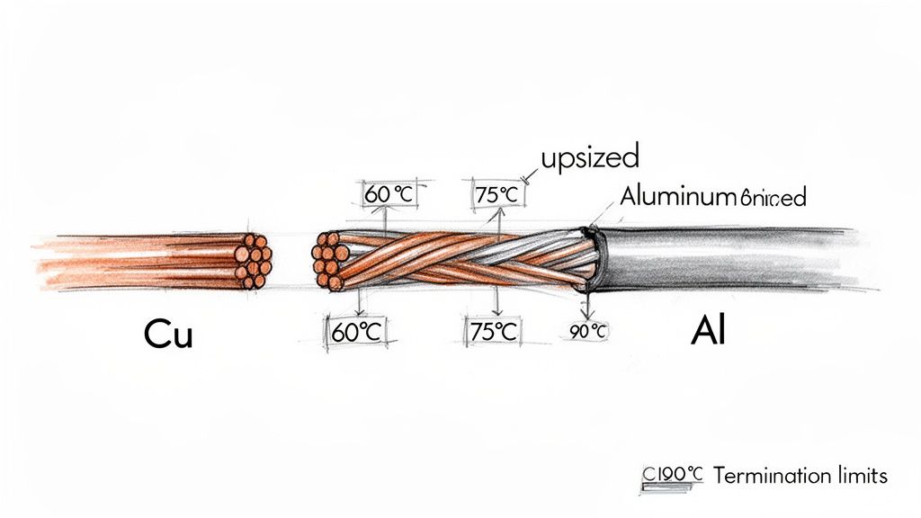
Environmental Conditions: Where is this breaker going? A standard unit might need to be de-rated at high altitudes because thinner air doesn't insulate as well. Extreme heat, cold, humidity, or corrosive salt air all demand specialized enclosures and materials.
Specific Load Types: Let's be honest, not all electrical loads behave the same. A breaker protecting a massive motor needs to ride out the intense inrush current on startup without a nuisance trip. Capacitor banks are another beast entirely, creating unique voltage stresses that demand a breaker specifically rated for that duty.
Control System Integration: How does this breaker talk to the rest of the plant? Modern facilities need breakers that play nice with SCADA or other control platforms. That means specifying the right control voltage, getting the auxiliary contacts you need for status feedback, and ensuring the communication protocols match up.
This level of upfront planning is the foundation of a reliable system. For a wider view on how these pieces fit together, our guide on electrical substation design is a great place to start.
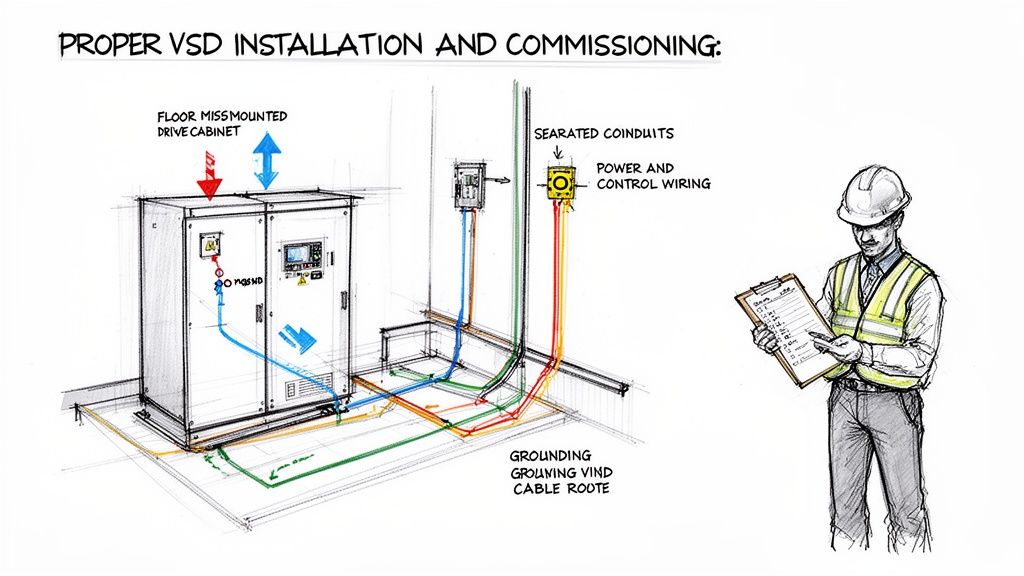
On-Site: Installation Best Practices
Once the right breaker shows up on site, the focus shifts to installation. This is a high-stakes job. We're talking about a heavy, sensitive piece of equipment that acts as the gateway for immense electrical power. Precision and safety are not optional.
Stick to these proven steps for a smooth installation:
Pre-Installation Inspection: Before it even comes off the truck, give it a thorough look-over for shipping damage. Check the integrity of the vacuum interrupters, insulators, and the main frame.
Safe Handling and Mounting: Always use the lifting points the manufacturer designed. No exceptions. Before you rack the breaker in, make sure the switchgear cubicle is spotless—no dust, debris, or forgotten tools. Confirm it’s seated securely and properly grounded.
Meticulous Electrical Connections: This is where so many failures begin. Every single power cable connection must be torqued to the exact value in the manual. Loose connections create hot spots and can lead to catastrophic failure. Make sure all the control wiring is routed neatly and secured so it won't get pinched or strained.
Safety is everything. The work area must be fully de-energized, locked out, and tagged out (LOTO). Everyone involved needs the proper Personal Protective Equipment (PPE). Even residual voltage can be lethal at this level.
Attention to detail here is more critical than ever. The global demand for reliable power is exploding, driven by a massive surge in renewable energy projects and grid modernization. That puts MV breakers right at the center of industrial power reliability—a core reason companies like E & I Sales engineer them into their advanced MV switchgear solutions. You can read more about this market's projected growth.
Final Checks: Commissioning and Energization
Before you flip the switch, there's one last critical phase: commissioning. This is your final chance to run a series of tests to prove the breaker is ready to do its job.
These pre-energization checks are non-negotiable:
Insulation Resistance Test: This "megger" test verifies that all the insulation is sound and hasn't been compromised by moisture or contamination.
Contact Resistance Test: A "ductor" test measures the resistance across the main contacts to ensure you have a solid, low-impedance path for current to flow.
Functional Trip Tests: You have to prove it works. Manually and electrically operate the breaker to confirm the trip coil, closing coil, and all the associated relays are responding exactly as they should.
Only after every one of these tests passes and is documented should you even think about energizing the breaker. This methodical, checklist-driven approach is what separates a successful project from a future failure, laying the groundwork for decades of safe, reliable operation.
Mastering Maintenance, Retrofits, and Upgrades
A medium voltage circuit breaker that runs reliably year after year isn't a matter of luck; it's the outcome of a smart asset management strategy. Being proactive isn't just about fixing things when they break—it's about getting ahead of failures before they ever happen, making sure your critical systems are always ready to go.
This means doing more than a quick visual inspection. It demands a disciplined approach to testing that can actually predict trouble on the horizon, giving you a chance to act. It also means knowing when it's time to stop patching up old, obsolete technology and make the strategic decision to upgrade. This forward-thinking approach is what separates a truly reliable facility from one that’s always putting out fires.
Building a Predictive Maintenance Program
Think of predictive maintenance like a doctor running routine tests during an annual physical. It uses diagnostic tools to monitor the health of your circuit breaker over time. The goal is to get hard data that helps you spot gradual wear and tear long before it causes a catastrophic failure.
Any solid program for a medium voltage circuit breaker should be built on three core diagnostic tests:
Insulation Resistance Test: Often just called a "megger" test, this is a fundamental health check for the breaker's insulation. By applying a high DC voltage, it checks for any current leakage that could point to moisture, contamination, or aging insulating materials. If you see those resistance readings trending downward over time, that's your warning sign.
Contact Resistance Test: This one is simple but critical. It measures the resistance across the main contacts when the breaker is closed. High resistance means hot spots, wasted energy, and potentially a violent failure under load. What you want to see is a low, stable micro-ohm reading, which confirms a clean, solid connection.
Functional Trip Tests: You can't just assume a breaker will do its job; you have to prove it. Functional tests are exactly what they sound like—you operate the trip and close circuits to make sure every mechanical and electrical part responds correctly and within the specified time. This is how you confirm the breaker can actually protect your system when it matters most.
These checks are the backbone of a maintenance strategy that keeps your gear dependable.
The Case for Retrofitting Legacy Breakers
Sooner or later, you reach a point where nursing along an old circuit breaker—especially those ancient oil or air-blast types—just doesn't add up anymore. The constant maintenance, the serious fire risk, and the nightmare of finding spare parts all build a powerful business case for a modern upgrade. This is where a retrofit comes in.
A retrofit is a smart solution where you replace the outdated, high-maintenance guts of a legacy breaker with a modern, reliable vacuum interrupter assembly. This new core is specifically designed to roll right into the existing switchgear cubicle. This means you minimize downtime and avoid the massive expense of replacing the entire switchgear lineup.
Retrofitting is more than just a technical fix; it's a strategic business move. By swapping an aging oil-filled medium voltage circuit breaker for a vacuum retrofit, facilities can slash maintenance costs by up to 80% while making huge gains in personnel safety and system reliability.
The benefits are immediate. You get the performance, safety, and reliability of a brand-new breaker with a fraction of the cost and installation headache.
Tangible Business Outcomes of an Upgrade
Upgrading your medium voltage circuit breakers isn't just an expense on a spreadsheet; it's a real investment with a clear and measurable payback. The technical improvements you make translate directly into business outcomes that plant managers and financial officers can get behind.
Let's connect the dots from the technical side to the business value:
Reduced Total Cost of Ownership: Modern vacuum breakers are practically maintenance-free. This completely eliminates the messy, expensive annual servicing that old oil breakers demand, cutting down on labor, materials, and hazardous waste disposal fees.
Enhanced Operational Safety: Getting flammable oil out of your switchgear is a massive win for fire prevention. On top of that, the faster clearing times of modern breakers dramatically reduce arc flash incident energy, making the entire work area safer for your people.
Decreased Unplanned Downtime: Let's face it, legacy breakers are a common source of failure. A modern retrofit gives you a huge boost in reliability, preventing the costly production losses that come from an unexpected outage.
When you decide to retrofit, you’re not just buying new equipment. You’re investing in a safer, more efficient, and more profitable operation for years to come.
The Future of Circuit Protection
The world of circuit protection is changing, and fast. What was once a simple protective device is now becoming a smart, data-driven cornerstone of a more reliable power grid, thanks to digitalization and a serious push for sustainability.
Think of it this way: the medium voltage circuit breaker is evolving. It's no longer just sitting there waiting for a fault. Modern breakers are packed with Internet of Things (IoT) sensors and advanced connectivity, turning them into self-monitoring assets. They're constantly tracking their own health—everything from internal temperature and how many times they've operated to the mechanical stress on their parts.
This firehose of data is what makes predictive maintenance a reality. Instead of scrambling when a failure brings everything to a halt, facility managers can now see problems coming. This transforms unexpected downtime into a scheduled, manageable maintenance event.
The Rise of Sustainable Alternatives
At the same time, the industry is making a necessary shift away from older technologies with a heavy environmental footprint. For years, Sulfur Hexafluoride (SF6) gas was the go-to for its fantastic insulating capabilities. The problem? It’s also a seriously potent greenhouse gas, and new global regulations are rightly pushing it out the door.
Stepping in to fill the gap is a new generation of eco-friendly alternatives. These technologies are engineered to deliver the same, if not better, performance without the environmental baggage, helping companies meet their ESG goals and comply with tougher government rules.
This innovation couldn't come at a better time. The market is absolutely booming, especially in the Asia-Pacific region, where huge industrialization projects and government-backed power infrastructure upgrades are driving demand. This explosive growth creates massive opportunities for global packagers like E & I Sales to deliver integrated MV switchgear and control systems. If you want to see the numbers behind this expansion, check out the latest market research on medium voltage breakers.
Navigating the Next Generation of Protection
This new era offers incredible potential, but it also brings a new layer of complexity. Picking the right technology, tying it into your existing control systems, and actually making sense of all the new data requires real-world expertise.
The future of grid reliability isn't just about faster breakers; it's about smarter systems. Leveraging new technology effectively means future-proofing your operations against both technical faults and evolving regulations.
This is where working with an experienced system integrator becomes so important. A good partner doesn't just help you choose the right digitally-enabled, sustainable medium voltage circuit breaker. They make sure it’s integrated seamlessly into your switchgear and automation platforms, turning new technology into a real-world advantage for your efficiency, safety, and long-term reliability.
Common Questions, Answered
Even after getting into the weeds of breaker technology, a few questions always seem to pop up. Let's tackle some of the most common ones to help tie everything together.
What’s the Real Difference Between a Medium Voltage and a Low Voltage Breaker?
It all comes down to the operating voltage and how they put out an electrical fire—the arc. A low voltage breaker (anything under 1,000V) is dealing with relatively low-energy faults, so simple air is often enough to snuff out the arc.
But a medium voltage circuit breaker (1kV-38kV) has a much bigger job. It has to tame immense fault energy, which demands some serious arc-quenching power. That’s where you see advanced methods like a high-power vacuum or SF6 gas, which are needed to extinguish the incredibly powerful arc safely and almost instantly.
How Often Do You Really Need to Maintain a Medium Voltage Breaker?
This really depends on the type of breaker, where it lives, and what the manufacturer recommends. Modern vacuum circuit breakers are the workhorses of the industry; they're incredibly reliable and don't ask for much. You might only need to inspect and test them every 5-10 years.
On the other hand, older oil or air-blast breakers are a different story entirely. Those require a lot more hands-on attention, often needing intensive servicing every single year.
If there's one thing to remember, it's this: always follow the original equipment manufacturer's (OEM) maintenance schedule. Sticking to their guidelines is the single best way to keep your medium voltage circuit breaker safe and reliable for the long haul.
Can I Swap Out an Old Oil Breaker for a New Vacuum Model?
Yes, you absolutely can—and you should. This upgrade is called a retrofit, and it’s one of the smartest investments you can make in your electrical system. Manufacturers have gotten very good at designing modern, direct-replacement vacuum breakers that slide right into the existing switchgear cubicles of those old, outdated models.
Making this switch does a few huge things for you. It immediately boosts safety by getting flammable oil out of your facility, slashes your ongoing maintenance costs, and dramatically improves the reliability and lifespan of your critical infrastructure.
For expert guidance on selecting, installing, or retrofitting your electrical protection systems, E & I Sales offers decades of experience in integrating custom UL control and MV switchgear solutions. Learn more at https://eandisales.com.
Let’s cut through the jargon. At its core, variable speed is about giving a motor a gas pedal instead of just an on/off switch.
Think about driving your car with the accelerator floored, using only the brake to control your speed—that’s basically how a traditional fixed-speed motor works. Variable speed technology is the game-changer that lets you dial in the motor’s speed to perfectly match the demands of the job, saving a ton of energy and reducing wear in the process.
Unlocking a Smarter Way to Run Motors
For decades, most industrial electric motors ran on a simple, brute-force principle: all or nothing. They were either off or roaring at full throttle, with zero middle ground. This fixed-speed approach is dead simple and reliable, but it’s incredibly inefficient for any application where the workload isn't constant.
To control the output, you had to rely on clunky mechanical devices like dampers, valves, or gears. It was a crude method, basically like driving with one foot slammed on the gas and the other on the brake to manage your speed.
Variable speed technology completely rewrites that playbook. By adding a smart controller, usually a Variable Frequency Drive (VFD), operators can fine-tune a motor's output with surgical precision. This isn't just a minor tweak; it’s a fundamental shift in how we manage industrial power and processes.
From Brute Force to Finesse
That old fixed-speed method wastes an unbelievable amount of energy. When a pump or fan only needs to run at 70% capacity, forcing it to go full blast and then mechanically choking its output is like trying to run a marathon in ski boots. Sure, you’ll get there, but you’ll burn way more energy than you needed to.
Variable speed control puts an end to that waste. It makes sure the motor only pulls the exact amount of power it needs to meet the current load. This simple concept leads to some massive advantages that are driving its adoption everywhere:
Serious Energy Savings: By matching motor speed to real-time demand, facilities can slash motor energy consumption by 20-50%, sometimes even more.
Tighter Process Control: Precise speed adjustments mean better product quality, less wasted material, and more nimble production lines that can adapt on the fly.
Reduced Mechanical Stress: Gentle starts and stops, often called soft-starting, get rid of the jarring electrical and mechanical shock of a direct-on-line start. This extends the life of everything from the motor itself to the belts, couplings, and gears connected to it.
A VFD gives a standard motor the intelligence to operate at its most efficient point for any given task. This is what moves industrial systems from a state of constant over-performance to one of optimized, demand-based operation.
To give you a quick visual, here’s how the two approaches stack up.
Fixed Speed vs Variable Speed At a Glance
This table breaks down the core differences between the old-school fixed-speed systems and modern variable speed setups. It highlights just how much more control and efficiency you gain.
Characteristic
Fixed Speed Systems
Variable Speed Systems
Speed Control
None. Runs at a single, constant speed.
Infinitely adjustable across a wide range.
Energy Efficiency
Low, especially at partial loads.
High, as power use is matched to the load.
Process Control
Crude. Relies on mechanical throttling.
Precise and responsive.
Mechanical Stress
High. Full-voltage starts are harsh on equipment.
Low. Soft starts reduce shock and wear.
Operating Cost
Higher due to wasted energy.
Lower due to significant energy savings.
As you can see, the move to variable speed is less of an upgrade and more of a complete evolution in motor control.
The impact of this technology is undeniable when you look at its market growth. The global VFD market is on track to jump from USD 23.85 billion in 2025 to USD 40.97 billion by 2034. That kind of growth underscores its vital role in modern industrial efficiency. You can dig deeper into these trends in this detailed VFD industry report.
How a Variable Frequency Drive Makes It All Happen
To really get what "variable speed" means in practice, you have to look inside the box—the Variable Frequency Drive (VFD), which is the brains behind the whole operation. A VFD isn't magic; it’s a sophisticated piece of power electronics that runs a three-stage conversion process to give you pinpoint control over a motor.
Think of it as a translator for electricity. It takes the raw, inflexible power from the utility grid and reshapes it into a new, custom-tailored electrical signal designed for one job: telling your motor exactly how fast to run.
This technology really took off during the industrial automation boom of the 1980s, but its roots go back to the 1970s oil crises. When global energy costs shot up by over 400%, the glaring inefficiency of just running motors at full blast all the time became a very expensive problem to ignore. If you're interested in the history, you can review industry intelligence on drive technology to see how it evolved.
The Three-Stage Power Conversion Process
The journey from a fixed AC input to a variable AC output happens in three distinct steps inside every VFD. Each stage has a critical job in molding the electricity into the perfect shape for precise motor control.
The Rectifier (AC to DC): First up, the VFD grabs the standard alternating current (AC) from your wall outlet and funnels it into a rectifier. This section is filled with diodes, which act like one-way gates for electricity. They effectively chop off the negative half of the AC sine wave, converting it into a rough, pulsating direct current (DC).
The DC Bus (Smoothing Things Out): This raw, bumpy DC isn't clean enough to work with yet. So, it flows into the DC bus, which is essentially a bank of large capacitors. These capacitors act like tiny, fast-acting batteries, soaking up the peaks and filling in the valleys of the pulsating DC. The result is a smooth, stable, and clean DC voltage.
The Inverter (DC Back to a New AC): Here’s where the real magic happens. The smooth DC power is sent to the inverter. This stage uses incredibly fast switches (transistors, usually IGBTs) that flicker on and off thousands of times per second. By chopping up the DC voltage in a very specific pattern, they build a brand-new, synthetic AC waveform from scratch to send to the motor.
This diagram shows you exactly how that three-step process flows, turning fixed utility power into a controllable output.
It’s a clear picture of how the VFD acts as the middleman, taking a fixed input and producing a totally variable output through its internal AC-to-DC-to-AC conversion.
Building the Perfect Wave with PWM
So how does the inverter turn a flat DC line into a beautiful, usable AC sine wave? It uses a clever trick called Pulse Width Modulation (PWM).
Creating a perfect, smooth AC sine wave electronically is complicated and expensive. Instead, the inverter fakes it by generating a rapid-fire series of rectangular DC pulses that have different widths.
It’s a bit like trying to draw a perfect circle using only tiny, straight Lego bricks. If you use enough small, carefully placed bricks, the final shape looks remarkably circular. PWM is the electronic version of that.
The VFD's inverter switches on and off so quickly, creating thousands of tiny voltage pulses. By precisely controlling the width and timing of these pulses, it builds a waveform that looks and acts like a true AC sine wave to the motor, letting it run smoothly at any frequency you command.
This method is stunningly efficient and gives the drive incredible control over both the frequency (speed) and voltage (torque) going to the motor. Want the motor to run slower? The VFD just creates the pulses at a lower frequency. Need more speed? It increases the frequency.
This elegant electronic sleight of hand is the core of how variable speed control becomes a practical, powerful reality in the real world.
The Top 3 Reasons to Make the Switch to Variable Speed
Let's get straight to it. Moving from a fixed-speed "all or nothing" motor to one with variable speed control isn't just a minor tweak—it's a fundamental shift in how your facility operates. The decision pays off in some seriously powerful ways, with benefits that show up everywhere from your monthly utility bill to the lifespan of your most critical machinery.
It really boils down to three game-changing advantages.
Benefit 1: Massive Energy Savings
If there's one reason that gets everyone's attention, it's the huge drop in energy consumption. Think about a fixed-speed system. The motor is either on or off, always running at full tilt, no matter the actual workload. To control the output, you're stuck using mechanical dampers or valves to choke the flow. It’s like flooring the gas pedal in your car while riding the brake to control your speed. Inefficient is an understatement.
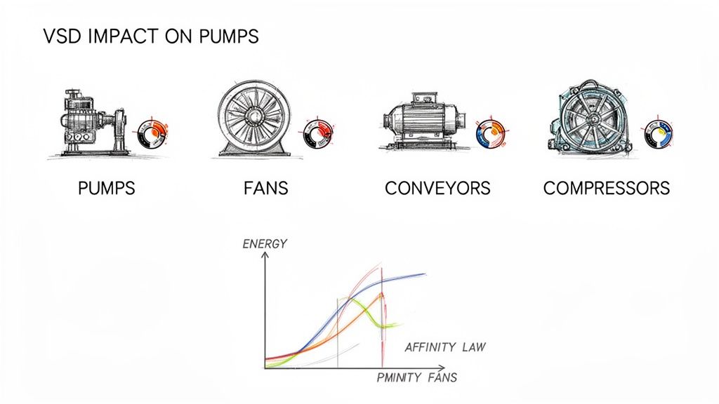
Variable speed control flips the script by perfectly matching the motor's power draw to what the load actually needs in real-time. This is a massive deal for pumps and fans, where a simple rule of physics known as the Affinity Laws comes into play.
The Affinity Laws are an engineer's best friend. They tell us that the power a fan or pump needs is tied to the cube of its speed. This creates an exponential relationship—a small drop in speed leads to a massive drop in power use. For example, slowing a fan down by just 20% can slash its energy consumption by nearly 50%.
That's the magic. Instead of wasting energy by running a motor at 100% and throttling it, a VFD just slows the motor down. The result? We regularly see energy consumption drop by 20-50%. That’s a direct hit to your operating costs and a big win for your carbon footprint. You can dig deeper into the numbers with our guide on calculating VFD energy savings.
Benefit 2: Fine-Tuned Process Control
Energy savings are great, but the precision you gain with variable speed is what transforms your entire operation. Fixed-speed systems are blunt instruments. Variable speed gives you a scalpel.
Picture a bottling plant conveyor. A fixed-speed motor means one speed, all the time. If production needs change, you're stuck. There’s no agility.
Now, add a VFD into the mix. Suddenly you can:
Synchronize multiple production lines to completely eliminate bottlenecks and pile-ups.
Dial in mixer speeds to get the perfect consistency every single time, whether you're making chemicals or cake batter.
Control pump flow rates with incredible accuracy for precise dosing and blending.
This level of control means less wasted material, a higher-quality final product, and a far more flexible manufacturing floor. You can finally adapt on the fly without ever compromising your standards.
Benefit 3: Less Wear, Tear, and Maintenance
Every time a standard motor fires up, it's a violent event. A direct-on-line (DOL) start unleashes a huge inrush of current—often 600% or more of the motor's normal rating. This slams the system with a sudden jolt of torque. It's the mechanical equivalent of getting rear-ended, and it happens every single time you start up.
This repeated shock brutalizes every component down the line, from motor windings and shafts to belts, couplings, and gearboxes.
This is where a VFD's "soft start" capability really shines. It gently ramps up the motor’s speed and voltage, completely eliminating that electrical surge and mechanical shock. This smooth, controlled acceleration dramatically reduces the stress on all your equipment.
The payoff is huge. Less stress means a longer life for your machinery, fewer surprise breakdowns, and way lower maintenance costs over the long haul. You're not just buying a drive; you're buying reliability.
Where Variable Speed Control Really Shines
Theory is great, but seeing how variable speed control works in the real world is where the lightbulb really goes on. This isn't some niche lab technology; it's the workhorse behind the scenes in countless industries, quietly saving money, tightening up processes, and improving final products everywhere from factory floors to high-rise office buildings.
The core idea is simple: match the motor's speed to the actual job at hand. Whether you're running a manufacturing line or a municipal water pump, ditching the old "all-or-nothing" fixed-speed approach for precise control is a total game-changer.
Let's look at a few places where this tech makes a massive difference.
Making HVAC Systems Smarter
Heating, Ventilation, and Air Conditioning (HVAC) systems are probably the most common and impactful place you'll find variable speed drives. Think about a big commercial building—the cooling and heating needs are all over the place during the day, changing with the number of people inside, the weather, and the time.
The Old Way: A fixed-speed fan or pump motor would just run at 100% power, all the time. To control the temperature, the system used mechanical dampers—basically metal flaps that block the vents. It's like flooring the gas in your car and using the brake to control your speed. Incredibly inefficient.
The VFD Way: With a VFD, the fan motor can just… slow down. When demand is low, instead of running at full tilt and fighting itself, the system simply dials the motor back to maybe 40% speed. Because of a principle called the Affinity Laws, that small drop in speed creates a massive drop in energy use. We're talking 30-50% savings on HVAC energy bills, easy.
Taming the Chaos of Conveyor Systems
In any factory or warehouse, conveyor belts are the lifeblood of the operation. They move products from A to B, and keeping that flow smooth is absolutely critical for preventing jams, damaged goods, and costly downtime.
A fixed-speed conveyor line is just asking for trouble. If one belt runs just a tiny bit faster than the one feeding it, you're going to get pile-ups and chaos. With variable speed control, each motor can be tuned perfectly to sync up with the others. This creates a single, seamless production line that can speed up or slow down in unison. That's the foundation of modern automation. If you want to dig deeper into how this works for specific motors, we have a great guide on AC motor variable speed control.
By enabling precise synchronization, variable speed control transforms a series of isolated machines into an intelligent, integrated production line. This eliminates guesswork and manual adjustments, leading directly to higher throughput and reduced waste.
Nailing the Perfect Mix, Every Time
When you're making food, pharmaceuticals, or specialty chemicals, consistency is king. Industrial mixers and extruders need exact speed control to get the texture, viscosity, or chemical reaction just right for every single batch.
A fixed-speed mixer is a blunt instrument. It's either on or off, which can mess up product quality or even ruin a whole batch if the mixing is too rough. Slap a VFD on there, and suddenly the operators have real control. They can:
Program custom mixing profiles with different speeds for different stages of the process.
Tweak the speed in real-time if the material gets thicker or thinner.
Use a gentle soft-start to keep expensive ingredients from splashing out.
This isn't just a nice feature; it's mandatory for meeting today's tough quality standards. And this thinking extends beyond the factory floor, too. You can see similar principles at play in cutting-edge fields like the latest innovations in electric propulsion for boats, where precise speed control is essential for efficiency and maneuverability.
How to Select and Integrate the Right VFD System
Picking the right VFD goes way beyond just matching horsepower ratings. If you want a system that's reliable, safe, and built to last, you need to think about the whole package—from the motor it’s controlling to the panel it lives in.
Getting these details right from the start is the difference between a smooth-running machine and a maintenance headache waiting to happen.
Let's walk through the big-ticket items you need to nail down to avoid common traps and spec a VFD system with confidence.
Ensuring Motor and Drive Compatibility
This is ground zero. Your first job is to make absolutely sure the motor is designed to play nice with a VFD. While you can technically run almost any AC induction motor with a drive, slapping one on a standard motor is just asking for a premature failure.
The rapid-fire voltage pulses from a VFD's output can chew through the winding insulation on a standard-duty motor. That’s why you always, always pair a VFD with an inverter-duty motor. These motors have beefed-up insulation systems built specifically to handle the electrical stress. It's the single best investment you can make for reliability.
Managing Heat Inside the Control Panel
VFDs are powerful pieces of electronics, and they throw off a surprising amount of heat. A drive can lose 2-3% of its throughput power just as heat. If that heat gets trapped inside a sealed control panel, temperatures can skyrocket, cooking sensitive components and dramatically cutting the VFD's lifespan short.
You can't afford to ignore thermal management. The basics include:
Proper Sizing: Give the drive some breathing room. A cramped enclosure is a hot enclosure.
Ventilation: Use filtered fans to create airflow, pulling in cool ambient air and pushing out the hot stuff.
Air Conditioning: For hot environments or panels packed with gear, a dedicated panel air conditioner is often the only way to keep electronics in their happy place.
Addressing Electrical Harmonics
Drives are what we call "non-linear loads." Instead of drawing power in a nice, smooth sine wave, they pull it in short, choppy bursts. This creates electrical "noise" on your power system called harmonics. Too many harmonics can wreak havoc, from overheating transformers to tripping breakers and messing with other sensitive equipment.
Think of harmonics as electrical pollution. One VFD might not be a big deal, but a dozen of them on the same system can poison your power quality and affect the entire facility.
A simple and effective first line of defense is a line reactor. It’s an inductor installed on the input side of the VFD that helps smooth out the current draw, cutting down on distortion. For tougher situations or where power quality standards are strict, you’ll need to explore more advanced options and learn about the different harmonic filters for VFDs to keep your system clean and stable.
The Importance of UL Panels and Proper Enclosures
Safety and compliance aren't optional. Specifying a UL-listed control panel (typically certified to UL 508A) is your assurance that the entire assembly was built to strict, nationally recognized safety standards. This isn't just a "nice-to-have"—it's often demanded by customers, insurers, and inspectors.
Finally, the box itself is your VFD's first line of defense against the real world. Choosing the right NEMA-rated enclosure is critical.
NEMA 1: Good for clean, dry, indoor spots.
NEMA 12: Keeps out dust, dirt, and dripping liquids.
NEMA 4/4X: Built for washdown duty, protecting against direct water spray. The 4X adds corrosion resistance for harsh environments.
To help tie all this together, here’s a practical checklist to run through when you’re specifying your next VFD package.
VFD Selection Checklist for Industrial Applications
Consideration Area
Key Questions to Ask
Why It Matters
Motor Compatibility
Is the motor rated for inverter duty? What is the motor's full-load amperage (FLA) and voltage?
Standard motors will fail prematurely. Matching electrical specs ensures the VFD can properly control and protect the motor.
Load Characteristics
Is it a variable torque (fan/pump) or constant torque (conveyor) load? Are there high starting torque requirements?
This determines the drive's required overload capacity (e.g., 110% for VT vs. 150% for CT) and influences sizing.
Thermal Management
What's the maximum ambient temperature? How much space is in the enclosure? Are other heat-producing devices nearby?
Overheating is a leading cause of VFD failure. Proper cooling (fans, AC) is non-negotiable for ensuring a long service life.
Power Quality
How many other VFDs are on the same transformer? Are there strict power quality requirements (e.g., IEEE 519)?
Prevents harmonics from disrupting other equipment in your facility and avoids potential utility penalties.
Enclosure & Environment
Will the panel be indoors or outdoors? Exposed to dust, moisture, or corrosive chemicals? Is it a washdown area?
The NEMA rating must match the environment to protect the electronics from contamination and damage.
Safety & Compliance
Does the application require a UL 508A listed panel? Are there specific customer or site-wide safety standards to meet?
Ensures the system is safe, insurable, and compliant with regulations, providing peace of mind and reducing liability.
By thinking through these areas from the start, you move from simply buying a drive to engineering a complete, reliable variable speed solution.
Keeping Your VFDs Healthy: Maintenance and Troubleshooting
Getting your variable frequency drive installed is just the beginning. To make sure it’s pulling its weight for years to come, you need a solid plan for its entire lifecycle. Think of it as three key pillars: a smart commissioning process, consistent maintenance, and knowing how to troubleshoot when things go wrong. These are what stand between you and costly downtime.
A great VFD implementation always starts with a careful, methodical startup. This is where you program the drive’s brain, telling it exactly how to manage the motor and its load. You’ll be setting crucial parameters like the acceleration and deceleration ramps, which guarantee smooth starts and stops that don't put unnecessary stress on your mechanical systems.
Another non-negotiable step is running a motor auto-tune. This clever function lets the VFD “get to know” the unique electrical personality of the motor it’s connected to. It builds a precise mathematical model, which allows the drive to dial in its output for the best possible performance and efficiency. The result is rock-solid control under any condition.
A Simple Preventive Maintenance Checklist
Once you're up and running, a simple preventive maintenance routine is your best friend. It’s all about catching the small stuff before it snowballs into a full-blown failure. Consider it a quick health checkup for one of your most critical pieces of equipment.
A proactive approach doesn't need to be a huge time-sink. Here are the essentials:
Look Around: Do regular visual checks for any signs of overheating, like discolored plastic or burnt-looking wires. Make sure all the connections are snug—vibration has a nasty habit of working them loose.
Keep It Clean: Dust is the enemy of all electronics. Every so often, power down the unit and give the VFD’s heat sinks and cooling fans a good cleaning. Proper airflow is vital to preventing overheating, which is hands-down one of the biggest causes of drive failure.
Check the Vitals: When the system is running normally, take a moment to check and log key data points like input voltage and output current. If you see these numbers start to drift from the baseline, it could be an early warning of a problem with the motor or the power coming in.
Proactive maintenance isn't a cost—it's an investment in uptime. A VFD that's kept clean, cool, and secure is a reliable VFD. Spending a few minutes on an inspection can easily save you hours or even days of lost production.
A Field Guide to Common Fault Codes
Even with the best maintenance, a VFD will occasionally throw a fault code to tell you something’s up. These codes aren’t just annoying alarms; they're diagnostic clues pointing you in the right direction. Knowing what the most common ones mean is the first step to getting back online fast.
Common Fault Code
Likely Cause(s)
First Troubleshooting Steps
Overcurrent (OC)
A sudden change in load, a short circuit, or accelerating way too fast.
Look for a mechanical jam; increase the acceleration time; inspect motor wiring for shorts.
Overvoltage (OV)
Regenerative energy from a high-inertia load, or stopping too abruptly.
Increase the deceleration time; you may need to add a dynamic braking resistor.
Undervoltage (UV)
The incoming power supply is unstable or just experienced a momentary dip.
Check that the input voltage is within the VFD's specified range; look for loose power connections.
By getting comfortable with these basic startup, maintenance, and troubleshooting steps, you can dramatically improve the reliability of any system that depends on variable speed technology. This knowledge helps you protect your investment and keep your operations running smoothly.
A Few Common Questions About Variable Speed Drives
When you start digging into variable speed technology, a few practical questions always pop up. Let's clear the air on some of the most common ones so you can make the right call for your equipment.
Can I Just Slap a VFD on Any Old Motor?
Technically, you can connect a VFD to a standard, off-the-shelf motor, but it’s a gamble you’ll probably lose. Standard motors simply weren't built to handle the unique electrical stress from a VFD's high-frequency voltage pulses. That stress chews through the winding insulation, leading to a much shorter, unhappier life for your motor.
The right way to do it is to always use an inverter-duty motor. These are built for the job, with beefed-up insulation systems that can take the heat from a VFD day in and day out. It's the only way to guarantee a long, reliable service life.
What's the Real Difference Between a VFD and a Soft Starter?
This one trips a lot of people up, but it's pretty simple. A soft starter has exactly one job: to gently ramp a motor up to its full, fixed speed. That's it. It’s a smooth on-ramp to the highway, preventing the massive electrical jolt of a direct start. Once the motor is at speed, the soft starter’s work is done.
A VFD, on the other hand, is the whole dashboard. It gives you that same gentle start, but it also lets you control the motor’s speed at any point. Think of it this way: a soft starter is just the on-ramp; a VFD is the gas pedal, the brake, and the cruise control all rolled into one.
How Much Energy Can I Actually Save?
For fans and pumps, there's a handy guideline called the Affinity Laws that gives you a surprisingly accurate estimate. These laws show that the power a motor uses is tied to the cube of its speed.
That relationship has a massive impact. It means a tiny reduction in speed delivers an outsized drop in energy consumption. For example, slowing a fan by just 20% (to 80% speed) can slash its energy use by nearly 50%. It’s one of the most powerful arguments for VFDs.
What's This "Harmonics" Thing I Keep Hearing About?
Harmonics are basically electrical noise—a distortion VFDs can introduce back into your facility's power grid. Think of them as unwanted ripples in an otherwise smooth electrical current. A single small VFD probably won't cause any trouble, but if you have a bunch of them running, that noise can add up.
When do you need to worry? If that distortion gets too high, it can cause real problems, like overheating transformers or tripping sensitive electronics. You’ll want to look at harmonic mitigation when VFDs make up a big chunk of your building's total electrical load or if you need to meet strict power quality standards like IEEE 519.
At E & I Sales, we don't just sell parts; we engineer complete, UL-listed control panels that get the job done right. From picking the perfect motor to commissioning the entire system, we build reliable, code-compliant packages designed to perform. Let us help you build your next project with confidence.
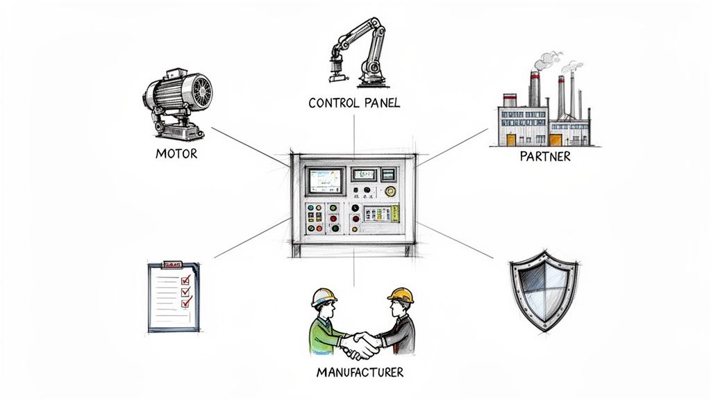
Think of an industrial control panel as the central nervous system for your entire automated operation. It’s what gives life to everything from a basic motor starter to a complex, multi-axis robotic cell. This isn't just another component you order off a shelf; it's the very core of your facility's safety, efficiency, and uptime.
That’s why picking a manufacturer is less like a simple purchase and more like entering into a long-term strategic partnership.
Choosing the Right Partner, Not Just a Panel Builder
Let’s be honest, anyone can stuff components into a box. What separates a true solutions provider from a basic assembly shop is their ability to deliver a fully engineered, code-compliant system that works seamlessly from day one. They do more than just build; they become an extension of your own engineering team.
This guide is designed to help you look past the spec sheets and see the bigger picture. We’re digging into what makes a premier partner—someone who delivers a complete solution that minimizes risk, cuts down on headaches, and gets your project across the finish line faster.
Why a Partnership Approach Matters
When you treat your manufacturer like a partner, you unlock a ton of value. Their experts can spot potential design flaws or compliance issues long before they become expensive problems on the shop floor. They provide the kind of guidance that only comes from years of hands-on experience, ensuring the final product is a perfect fit for your operational needs.
This collaborative mindset is crucial, especially in an industry that's growing like crazy. The global industrial control panel market is already a giant, valued at around $15 billion in 2025, and it’s expected to blow past $25 billion by 2033. This surge is all thanks to the non-stop push for more automation in manufacturing, energy, and just about every other sector. A solid partnership ensures you’re not just keeping up, but leading the pack.
What to Expect from a Top-Tier Manufacturer
A top-tier control panel builder brings a lot more to the table than just assembly work. Their value is in the comprehensive support they provide from the initial concept all the way through commissioning.
Deep Engineering Expertise: They live and breathe the nuances of UL-listed systems, motor control centers (MCCs), and how to integrate everything without a hitch.
Proactive Problem Solving: The best partners anticipate problems. They’ll question a drawing or suggest a better component before it ever causes a delay.
Turnkey Solutions: Many of the best shops offer the whole package—design, fabrication, programming, and even on-site startup support.
The right manufacturer delivers more than just hardware; they deliver confidence. It's the confidence that comes from knowing your control systems are built to the highest standards of safety, quality, and reliability, ready for seamless integration and built to last.
Ultimately, the goal is to find a partner who can provide a complete, dependable solution that’s truly built for your specific application. That starts with understanding the difference between someone who just builds panels and a partner who builds solutions.
Decoding Essential Certifications and Capabilities
When you're vetting industrial control panel manufacturers, it’s easy to get fixated on the price tag. But the real story isn't in the quote; it's in their core competencies. Not all panel shops are built the same, and their certifications and proven capabilities are the true measure of quality, safety, and long-term reliability.
Think of it like hiring a specialized surgeon. You wouldn’t shop around for the cheapest option, would you? You’d be looking for board certification, a track record of success with complex procedures, and deep expertise. The same logic applies here. A manufacturer’s credentials aren't just logos on a website—they're your assurance that they have the documented processes and expertise to build a panel that’s safe, compliant, and ready for the plant floor.
The Gold Standard: UL 508A Certification
In North America, one certification stands above all others: UL 508A. This is the undisputed gold standard for industrial control panels. When a shop is certified by Underwriters Laboratories (UL), it means they are authorized to design, build, and apply the UL mark to panels that meet incredibly rigorous safety standards. The program audits everything from how they select components and route wires to the enclosure ratings they use.
Having that UL 508A label on your panel is a massive advantage. It dramatically simplifies the final inspection process on-site. When the Authority Having Jurisdiction (AHJ) sees that mark, it serves as immediate proof of compliance, helping you avoid costly and frustrating delays during commissioning. It is the single most important credential to look for. To get a better handle on the specifics, you can learn more about the differences between UL Listed vs. UL Recognized components in our detailed guide.
A UL 508A certified shop isn't just following a rulebook; they're demonstrating a deep-rooted culture of safety and quality control. This certification validates that their entire process—from design to final testing—is built to mitigate electrical hazards and ensure operational integrity.
Core Technical Capabilities to Verify
Beyond the paperwork, a top-tier partner needs to have a broad arsenal of technical skills. A simple assembly shop might be fine for basic relay logic, but modern industrial processes demand a whole lot more. It’s also critical to ensure your partner is up-to-date with evolving regulations, like the Cyber Resilience Act (CRA) and its associated CRA Manufacturer Obligations.
Here are the key capabilities that separate a true engineering partner from a basic assembler:
Motor Control Centers (MCCs): If your facility runs a lot of motors, expertise in designing and building MCCs is non-negotiable. An experienced manufacturer knows how to create centralized, modular systems that make maintenance easier, improve safety, and are built for future expansion.
Variable Frequency Drives (VFDs): Anyone can mount a VFD in a box, but properly integrating one for energy efficiency and precise motor control is an art. This means understanding heat dissipation, harmonic mitigation, and the right programming to optimize performance and prevent premature equipment failure.
Medium Voltage (MV) Switchgear: Working with equipment above 600V is a whole different ballgame. The ability to handle medium voltage applications is a highly specialized skill that requires advanced engineering knowledge and a strict adherence to safety protocols that many shops simply don't have.
Verifying these capabilities upfront ensures your manufacturer can handle the full scope of your project. You'll get a robust, integrated solution—not just a collection of parts in an enclosure.
Evaluating Design Engineering and Quality Control
A great control panel isn't just about skilled wiring; it’s born from a disciplined engineering process. The real difference between a reliable, workhorse panel and a source of constant frustration often comes down to the manufacturer's commitment to a structured design workflow and relentless quality checks. This is where you separate the mere assemblers from true engineering partners.
Top-tier industrial control panel manufacturers don't just build to a print you hand them. They dig in. They question it. They scrutinize your specifications to spot potential issues, check for compliance with NEC and NFPA standards, and make sure the design is truly robust and maintainable. This kind of proactive thinking prevents costly mistakes from getting "wired in" from the very beginning.
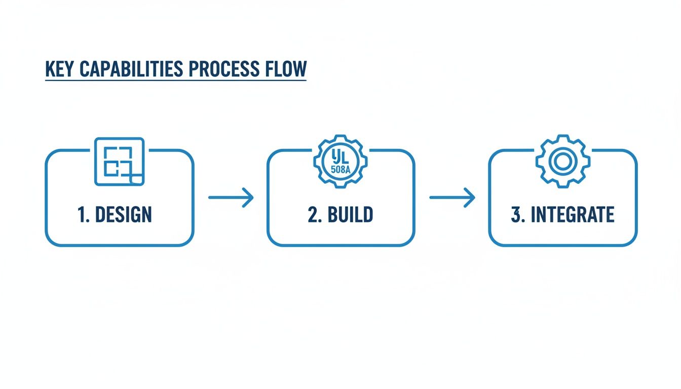
This flow chart gives you a bird's-eye view of a quality-driven manufacturing process.
It really highlights how a disciplined workflow should move seamlessly from the initial design and engineering phase, through certified assembly, and into the final system integration.
The Blueprint for Reliability
A manufacturer's design process is the absolute foundation of quality. Today, modern panel shops lean heavily on advanced CAD software to create precise electrical schematics and detailed 3D panel layouts. These digital models aren't just pretty pictures; they allow engineers to verify component clearances, plan out clean wire routing, and generate dead-on accurate bills of material before anyone even drills a single hole.
When you're evaluating a partner, ask them about their design tools and how they document everything. A well-documented process is a dead giveaway of a mature and reliable operation. If you want to get into the nitty-gritty, our guide on industrial control panel design offers a much deeper dive.
The Quality Management System
So, how does a manufacturer guarantee that the thousandth panel they build is just as perfect as the first? The secret is their Quality Management System (QMS). A real QMS isn't just a dusty binder on a shelf; it’s a living, breathing framework that dictates every single step of production, from receiving to shipping. When vetting a manufacturer, it’s critical to ask about their adherence to robust standard operating procedures.
A strong QMS will always include several key pieces:
Document Control: A formal system for managing schematics, revisions, and work instructions. This ensures every technician is working from the latest, correct version. No excuses.
Component Verification: A process for checking every incoming part against the bill of materials to catch mistakes before they get anywhere near the assembly floor.
In-Process Checks: Point-to-point wiring verification and component torque checks that happen during the build, not just at the final inspection.
Functional Testing: A full power-up test and functional simulation of the panel's logic. This confirms it operates exactly as intended before it ever leaves their shop.
Quality control isn't a single event at the end of the line; it’s a series of checkpoints integrated throughout the entire design and build process. This continuous verification is what guarantees consistency, reliability, and safety in every panel delivered.
Before we move on, here’s a quick checklist you can use to frame your conversations with potential partners.
Key Manufacturer Evaluation Criteria
Evaluation Area
What to Look For
Why It Matters
Design Engineering
Use of modern CAD/CAE tools, schematic review process, 3D panel layouts, revision control.
Ensures design accuracy, proper component fit, and that everyone is working from the correct set of prints.
Provides a framework for repeatable quality and consistency from the first panel to the last.
Component Sourcing
Verification of incoming parts against the BOM, use of authorized distributors, counterfeit part avoidance policies.
Guarantees that the specified components are actually what get installed, preventing performance issues.
Testing & Validation
Full power-up functional testing, I/O simulation, detailed factory acceptance test (FAT) procedures.
Verifies the panel operates exactly as designed before it arrives at your facility, minimizing startup delays.
Documentation
As-built drawings, component manuals, test reports, and a complete final documentation package.
Critical for installation, troubleshooting, and long-term maintenance of the system.
Ultimately, a manufacturer with a transparent and well-documented process isn't just selling you a product. They’re delivering the peace of mind that comes from knowing your critical systems are built correctly, documented thoroughly, and ready to perform for years to come.
Looking Beyond the Build to Integration and Support
An industrial control panel isn’t a gadget you just plug in and forget. Its real job only starts when it's talking perfectly with every other motor, sensor, and PLC on your plant floor. The project isn't done when the panel ships out; in many ways, it's just getting started.
This is exactly why the best industrial control panel manufacturers are the ones who stick around for the whole journey. They don't just build a box and send an invoice. They’re the ones who bridge that critical, often-tricky gap between the panel they built and the process you need it to control. It's the difference between a simple transaction and a genuine partnership.
From Their Factory Floor to Your Floor
A top-tier partner offers services that go way beyond their own four walls. They get that a smooth transition from installation to full-blown production is everything. This is where services like on-site integration and commissioning become absolute game-changers, helping you sidestep huge project risks and costly delays.
Think about a major plant upgrade. The shiny new control panel arrives, but now you have to connect it to a web of existing machinery, legacy sensors, and your plant’s network. That’s a massive headache waiting to happen. A manufacturer who sends their experts to your site turns that potential nightmare into a smooth, managed process.
These critical post-build services usually include things like:
Factory Acceptance Tests (FAT): This is your chance to see the panel run under simulated plant conditions before it ever leaves their shop. It’s a crucial step to make sure everything works as designed, catching issues early.
On-Site Commissioning Supervision: Having an expert from the panel shop on-site during startup is invaluable. They know the system inside and out, can troubleshoot problems on the fly, and ensure it integrates cleanly with your existing equipment.
Operator and Maintenance Training: A great partner doesn’t just hand over the keys and walk away. They make sure your team knows how to operate the new system and perform basic maintenance, setting you up for long-term success.
A manufacturer's responsibility shouldn't end at the shipping dock. True project ownership means ensuring the solution performs not just in their shop, but in your facility, under real-world production demands. This commitment to integration and support is a key differentiator.
The Real-World Impact of Full-Lifecycle Support
Let’s play out a common scenario: a manufacturer ships the panel and a bill, and that’s it. Your team is left digging through schematics, wrestling with the integration, and trying to squash programming bugs. This hands-off approach almost always leads to extended downtime, blown deadlines, and a whole lot of frustration.
Now, picture it with a partner who sees the project through. Their engineer is on-site, supervising the installation and working right alongside your technicians to commission the system. They make sure your operators are comfortable with the new HMI screens before they leave. This hands-on approach catches small problems before they balloon into big ones and can easily shorten your startup timeline by days or even weeks.
Ultimately, picking a manufacturer is about so much more than the physical build quality. It’s about finding a team that’s invested in your success long after the last wire is terminated. That holistic support is what ensures your new system actually delivers on its promise of better safety, efficiency, and reliability from day one.
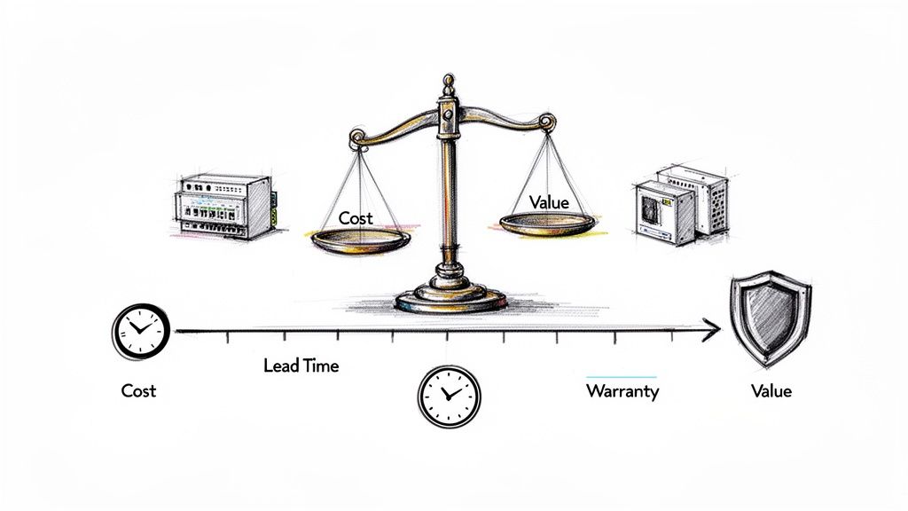
Understanding Cost, Lead Times, and Long-Term Value
When you're sourcing an industrial control panel, it's tempting to just compare the final numbers on the quotes. But the initial price tag is only one piece of a much larger puzzle. The real value comes from finding the sweet spot between upfront cost, production timelines, solid warranty coverage, and the long-term reliability of that panel on your floor.
Think about it like buying a new CNC machine. You wouldn't just grab the cheapest one without digging into its performance specs, expected lifespan, and the kind of support you'll get when something inevitably goes sideways. You have to apply that same strategic thinking to your control panels. A slightly higher investment today in better components or a more thoughtful design can easily pay for itself a hundred times over by preventing even a single hour of unplanned downtime tomorrow.
Key Factors That Drive Panel Costs
A few key things really move the needle on the final quote you'll get from industrial control panel manufacturers. Getting a handle on these drivers means you can have much better conversations with potential partners and make smart trade-offs.
Component Selection: The brands you call out for the big-ticket items—PLCs, VFDs, circuit breakers—are a huge cost driver. Sure, sticking to your plant standard makes life easier for your maintenance team, but having some flexibility can open up options for more cost-effective or, more importantly, available alternatives.
Enclosure Type and Rating: The box itself really matters. A basic NEMA 1 enclosure for a clean, dry room is a world away from the cost of a NEMA 4X stainless steel cabinet built to survive a corrosive chemical washdown.
Design Complexity: The more you ask the panel to do, the more it's going to cost. Things like high I/O counts, complex programming logic, and custom-crammed back panels all add up in both engineering and assembly labor.
Navigating Production Lead Times
In today's world, lead times are everything. A standard custom control panel build can take anywhere from 4 to 12 weeks, but that number can swing wildly. The biggest wildcard is almost always the availability of a key component. A single, specific PLC or drive on backorder can bring your entire project to a screeching halt.
Don't just ask, "What's your lead time?" A much better question is, "What are the long-lead items in my design, and are there any good alternatives we should look at to speed things up?" This simple shift puts you in the driver's seat and can keep your project moving.
The True Meaning of a Strong Warranty
Last but not least, don't just glance at the warranty. A manufacturer's warranty is a direct statement about how much they believe in their own work. A flimsy warranty might cover a faulty part, but it'll leave you holding the bag for the labor to swap it out.
A truly great warranty, on the other hand, backs the whole package. It should cover the parts, the workmanship, and the integrity of the design itself. This is your assurance that the panel was built right from the start and that the builder will be there for you, giving you peace of mind long after the check has cleared.
Tying Up Loose Ends: Your Final Questions Answered
Even after you've done your homework and narrowed down the list, a few lingering questions always seem to pop up. Getting straight answers to these final-stage queries is what separates a good choice from a great one, giving you the confidence that you're picking the right industrial control panel manufacturer.
Think of this as the last gut check before you sign on the dotted line. These are the practical, real-world questions that truly reveal how a partner operates.
What’s the Big Deal with UL 508A Certification?
In North America, the UL 508A certification is the gold standard, and honestly, it should be non-negotiable. It means a manufacturer has been audited by Underwriters Laboratories (UL) and has proven they can build panels to an incredibly high, nationally recognized safety standard. It’s not just a sticker on the box; it's a guarantee that their entire process—from how they select components to their specific wiring techniques—is designed to prevent fires and electrical hazards.
For you, a UL-listed panel delivers two huge wins. First, you get an immediate baseline of quality and safety you can count on. Second, it makes life infinitely easier during on-site electrical inspections. When the Authority Having Jurisdiction (AHJ) sees that UL mark, they recognize it as proof of compliance on the spot, which helps you dodge expensive delays when you’re trying to get up and running.
How Can I Get the Most Accurate Quote?
The quote you get back is only as good as the information you put in. To get a price that’s both accurate and competitive, your scope of work needs to be buttoned up. The more detail you provide upfront, the less guesswork the panel shop has to do—and guesswork always costs more.
To set them (and yourself) up for success, be sure to include:
A complete bill of materials that calls out your preferred brands for major hardware like PLCs and VFDs.
A sequence of operations that spells out, in plain English, how the system is supposed to work.
A detailed I/O (Input/Output) list that accounts for every single connection point.
All motor and load information so they can size circuit protection correctly.
The specific enclosure you need, like a NEMA 4X stainless steel unit for a washdown environment.
If you have existing electrical drawings or P&ID diagrams, send them over. That level of detail is worth its weight in gold and ensures the quote you get is for the panel you actually need.
What's the Difference Between a System Integrator and a Panel Shop?
It's a great question, and the lines can definitely get blurry. A dedicated control panel manufacturer is laser-focused on the physical world inside the enclosure. They specialize in the design, assembly, wiring, and testing of the panel itself, all based on a set of engineering prints.
A system integrator, on the other hand, usually takes a wider, 10,000-foot view. They’re often responsible for designing the complete automation system, which includes programming the PLC and HMI, and then integrating that new panel with all the other machines, sensors, and software on your factory floor.
The real magic happens when you find a partner who does both. A company that can handle everything from fabricating the panel to commissioning the system on-site offers a huge advantage. It creates a single point of responsibility, which streamlines the project, kills communication gaps, and eliminates the finger-pointing that can happen when you have two different vendors.
Ready to partner with a team that offers deep expertise in both custom UL control panel manufacturing and full-system integration? E & I Sales has been delivering reliable, code-compliant solutions since 1974. Connect with our experts today to discuss your next project by visiting us at https://eandisales.com.
A control transformer isn’t just another component in an electrical cabinet; it’s the dedicated power supply that keeps your control circuits running smoothly and safely. At its core, it's an isolation transformer that takes high, often dangerous, system voltages and steps them down to a more manageable level, like 120V or 24V.
This stepped-down voltage is what powers the brains of the operation—the relays, timers, contactors, and other sensitive electronics that manage an entire industrial process.
The Unsung Hero Inside Your Control Panel
Picture a massive industrial machine. Its powerful motors might be chugging along on 480V, but the delicate control circuits orchestrating every move can't handle that kind of power. This is where the control transformer steps in, acting as the quiet guardian for the machine’s most critical electronics.
It’s helpful to think of the difference this way: a standard power transformer is like the utility pole bringing electricity to an entire neighborhood—it’s powerful but indiscriminate. A control transformer, on the other hand, is like a high-end, dedicated power conditioner for your most expensive piece of audio equipment. It’s not just about changing the voltage; it's about delivering clean, stable, and reliable power precisely where it matters most.
Why Is This Stability So Important?
When you fire up an industrial machine, components like motor starters, solenoids, and relays demand a massive, instantaneous surge of current to get going. This is called inrush current, and it can cause a momentary voltage drop—or "sag"—across the entire control circuit.
If that voltage dips too low, things start to go wrong. Relays might fail to pull in, contactors can chatter, and PLCs could glitch. A standard transformer would buckle under that sudden demand.
Control transformers, however, are built for this abuse. They are specifically engineered with low impedance windings to handle huge inrush currents without breaking a sweat. This ensures that even when a big motor contactor slams shut, the voltage feeding your sensitive PLC remains rock-solid.
A well-designed control transformer can handle inrush currents up to 10-12 times its nominal rating. This is its superpower, preventing voltage sags that could otherwise cause chaos in an automated system.
This built-in toughness is what makes control transformers non-negotiable for reliable automation. For any company building UL-listed control panels, choosing the right transformer is a foundational step in minimizing costly downtime for the end-user. After all, a solid industrial control panel design always starts with a stable power source.
To put it all together, here’s a quick overview of what a control transformer brings to the table.
Control Transformer at a Glance
Function
Key Characteristic
Primary Benefit
Voltage Regulation
Provides stable, stepped-down voltage (e.g., 480V to 120V) for control circuits.
Protects sensitive components and ensures consistent operation.
Inrush Management
Designed to handle high momentary inrush currents from inductive loads.
Prevents voltage sags that can cause device malfunction or failure.
Electrical Isolation
Creates a physical separation between the high-voltage power source and the control circuit.
Enhances safety for operators and protects electronics from power line noise.
In short, this small but mighty component is the bedrock of any modern industrial control system, ensuring machinery operates safely, efficiently, and without interruption.
How Control Transformers Differ From Other Transformer Types
It's a lot easier to wrap your head around what a control transformer is when you see it side-by-side with its more common cousins. While all transformers play with voltage, what’s going on inside—their design—is what really matters. Picking the wrong one is like trying to haul a load of gravel with a sports car. Sure, it might move an inch, but it’s built for a totally different kind of stress and won’t last long.
The electrical world has a whole family of transformers, each with a specific job. To steer clear of costly mix-ups and keep your systems humming, you've got to understand what makes a control transformer the special tool it is. The key differences aren't just in what they do, but in how they're built to survive the chaotic demands of industrial control circuits.
Control Transformer vs. Power Transformer
The most frequent point of confusion is between control transformers and the standard power (or distribution) transformers you see everywhere. A power transformer is all about efficiency and steady, predictable loads. Its job is to deliver bulk power to a facility or a big machine with as little energy waste as possible. It’s happiest with a relatively constant, predictable current draw.
A control transformer, on the other hand, is a specialist built for chaos. It’s engineered to handle the massive, but very brief, inrush currents that come from energizing inductive components like solenoids, relays, and motor contactors. We're talking about a momentary surge that can be 5 to 15 times the component's normal operating current.
A standard power transformer would see that surge as an overload and its output voltage would plummet. That voltage sag would cause your control components to stutter or fail, bringing the whole system down.
Think of it this way: a power transformer is a marathon runner, built for steady, long-distance performance. A control transformer is a weightlifter, engineered to handle immense, explosive bursts of effort without even flinching.
This is because its windings have a lower impedance, which is the secret to maintaining stable voltage even when it gets hit with a sudden, heavy load.
The Role of Isolation Transformers
An isolation transformer is all about safety and cleaning up electrical noise. It almost always has a 1:1 turns ratio, which means the voltage you put in is the same as the voltage you get out (e.g., 480V in, 480V out). Its claim to fame is the complete electrical separation—often called galvanic isolation—between its primary and secondary windings.
This separation creates a brand-new, isolated power source on the secondary side. This is great for protecting sensitive electronics from electrical noise and creating a much safer environment for anyone working on the equipment.
Now, here's the key: all control transformers are technically isolation transformers (they separate the high-voltage primary from the low-voltage control circuit). But not all isolation transformers are control transformers. A standard isolation transformer just isn't built with the muscle needed to handle the brutal inrush demands of a control circuit.
Understanding the Autotransformer
An autotransformer is the odd one out. It uses just one winding that serves as both the primary and the secondary. By using different connection points, or "taps," along this single coil, it can step voltage up or down. Because of this clever design, they are often smaller, lighter, and cheaper than their two-winding relatives.
But that efficiency comes with a huge trade-off: autotransformers provide zero electrical isolation. There’s a direct physical connection between the input and output circuits. This complete lack of separation makes them totally unsuitable and dangerous for most control panel applications, where keeping operators safe and protecting delicate electronics is non-negotiable. You’ll usually find them in places like motor starting circuits where isolation isn’t a priority.
To really nail down these differences, let's put them all in one place.
Control Transformer vs. Other Transformer Types
This table breaks down the key distinctions between these common transformer types.
Transformer Type
Primary Purpose
Inrush Current Handling
Typical Application
Control Transformer
Provide stable, low-voltage power for control circuits with high inductive loads.
Excellent. Specifically designed to handle high inrush without significant voltage drop.
Industrial control panels for PLCs, relays, contactors, and solenoids.
Power Transformer
Efficiently transfer bulk electrical power at a steady rate.
Poor. Not designed for sudden, high-demand surges; voltage will sag.
Utility distribution, building power, and supplying main machine power.
Isolation Transformer
Create electrical separation for safety and noise filtering.
Poor. Not typically designed for high inrush unless specified as a control type.
Medical equipment, sensitive laboratory instruments, and data centers.
Autotransformer
Step voltage up or down economically without isolation.
Poor. Lacks isolation and is not built for the demands of control circuits.
Motor starting circuits (reduced voltage starters) and some power grids.
At the end of the day, a control transformer is a purpose-built beast. It gives you the safety of an isolation transformer combined with the raw strength needed to regulate voltage under the toughest industrial conditions, making it an absolutely essential part of modern automation.
Cracking the Code on Transformer Ratings and Specs
Picking the right control transformer isn't about grabbing the biggest one off the shelf. It’s a precision game. You’re matching its DNA—its specifications—to the exact needs of your control circuit. These ratings aren't just numbers on a label; they're the blueprint for a reliable, safe, and effective system. Get this right, and you prevent a world of headaches.
The first spec you'll run into is the VA (Volt-Amps) rating. Think of this as the transformer's total power budget. It tells you the apparent power it can handle. To figure out the maximum continuous current the secondary can supply, just divide the VA rating by the secondary voltage. For instance, a 500 VA transformer with a 120V secondary is good for a steady 4.17 amps. Simple enough, right?
But "steady" is a luxury in the industrial world. Control circuits are all about starts and stops, which brings us to the most critical part of sizing: understanding the two very different kinds of power demand.
Sealed VA vs. Inrush VA: The Two Sides of Power Demand
Imagine you're trying to push a heavy cart. That first shove to get it moving takes a huge, concentrated effort. But once it's rolling, keeping it going is way easier. That's a perfect picture of how control components use power.
Sealed VA: This is the "keeping it rolling" power. It's the continuous, low-level energy your components need just to stay on—think energized relays, timers, and PLC processors.
Inrush VA: This is that massive, initial shove. It’s the momentary surge of power needed to energize an inductive device like a motor contactor or a solenoid. This jolt can be 5 to 15 times higher than the sealed VA.
Your transformer has to be beefy enough for both. If you only size for the sealed VA, the transformer's voltage will tank the moment that inrush hits, and your control system will stumble right at startup.
As you can see, a control transformer is really a specialized type of isolation transformer, built from the ground up for the unique demands of industrial control circuits, setting it apart from its general-purpose power transformer cousins.
Voltage Ratings and Temperature Rise
Beyond VA, the voltage ratings are non-negotiable. The primary voltage has to match your incoming power (like 480V or 240V), and the secondary voltage needs to match what your control components are designed for (typically 120V or 24V). Thankfully, many control transformers come with multi-tap primaries, giving you some much-needed flexibility to handle different supply voltages on-site.
Another spec to watch is temperature rise. This tells you how much hotter the transformer's windings will get than the surrounding air when it's running at full tilt. A 115°C rise is pretty standard, meaning it can operate that much hotter than the ambient temperature without breaking down. But if you’re installing it in a hot environment, grabbing a transformer with a lower temperature rise (like 80°C) is a smart move that can seriously extend its working life.
UL and NEMA Compliance: Your Seal of Approval
Last but not least, always look for the UL (Underwriters Laboratories) and NEMA (National Electrical Manufacturers Association) marks. These aren't just stickers. They are your proof that the transformer has been put through the wringer and passed strict safety and performance tests. UL 508, for example, is the gold standard for industrial control gear.
Choosing a compliant transformer means you're getting a product built with quality insulation that can handle its rated load without becoming a fire or shock hazard. For anyone building UL-listed control panels, using certified components isn't just a good idea—it's a requirement.
A Practical Guide to Sizing Your Control Transformer
Getting the size of your control transformer right is more of a science than a guessing game. If you go too small, you're signing up for frustrating voltage drops and mysterious system failures. Oversize it, and you're just wasting money and precious panel real estate.
The good news is there's a straightforward process to nail the sizing every single time. Let's walk through a real-world example to see how it's done, covering both the steady-state power draw and that all-important inrush surge.
Step 1: Tally Your Continuous Power Needs
First things first, we need to figure out the sealed VA. This is the continuous power your components need just to stay on and do their jobs. Think of it as the baseline power needed to keep the lights on inside your control circuit.
Start by making a list of every single device that will be powered by the transformer's secondary winding. This means PLCs, timers, relays, pilot lights, and the coils inside contactors and motor starters—everything.
Once you have your list, dig into the manufacturer datasheets to find the sealed VA rating for each component. Let’s put together a list for a typical motor control panel:
Programmable Logic Controller (PLC): 30 VA
Active Timers (2): 5 VA each (10 VA total)
Control Relays (6): 4 VA each (24 VA total)
Pilot Lights (4): 3 VA each (12 VA total)
Motor Starter Coils (2): 15 VA each (30 VA total)
Now, just add it all up: Total Sealed VA = 30 + 10 + 24 + 12 + 30 = 106 VA
That 106 VA is the constant, everyday load your transformer will be handling.
Step 2: Calculate the Critical Inrush VA
This next part is where a control transformer really earns its keep: handling the inrush current. This is that massive, split-second surge of power needed to energize inductive loads like contactors, solenoids, and relays.
For this calculation, you only need to worry about the components with a big inrush demand that could all kick on at the exact same moment. Looking at our list, the motor starter coils are the main culprits here. Go back to the datasheets and find their inrush VA rating.
Let's say each motor starter coil has an inrush rating of 150 VA. If there's any chance both could start simultaneously, you have to account for that combined surge.
Total Inrush VA = 150 VA + 150 VA = 300 VA
This is the peak load your transformer has to endure without letting its output voltage sag below a critical point, which is usually 85% of its nominal rating.
Step 3: Determine the Total Design VA
Okay, we have our sealed VA and our inrush VA. Now we can figure out the total power requirement for the transformer. The formula is surprisingly simple:
Total Design VA = √( (Total Sealed VA)² + (Total Inrush VA)² )
Let’s plug in the numbers from our example: Total Design VA = √( (106)² + (300)² ) Total Design VA = √( 11,236 + 90,000 ) Total Design VA = √( 101,236 ) Total Design VA ≈ 318 VA
This number represents the minimum VA rating you need to handle both the steady load and the momentary peak demand. When you're planning a project with many components, using a tool like electrical estimating software can seriously speed up the process of getting these specs right.
Step 4: Select a Transformer with a Safety Margin
Our math tells us we need a transformer rated for at least 318 VA. But in the real world, you never want to spec something that just barely meets the minimum. It's smart to build in a safety margin for future upgrades, unexpected loads, or even just a hot day in the plant.
A safety margin of 20-25% is a solid rule of thumb. This gives you breathing room for expansion and keeps the transformer from running at its max limit all day, which will definitely help it last longer.
Let's apply a 25% safety margin to our number: Required VA Rating = 318 VA * 1.25 = 397.5 VA
With a final requirement of 397.5 VA, you'd look at standard transformer sizes and simply pick the next size up. In this case, a 500 VA control transformer is the perfect choice, giving you plenty of capacity for rock-solid reliability and any future needs.
Proper sizing is also your first line of defense against problems like excessive voltage drop; you can dive deeper into that topic by learning about voltage drop calculation formulas.
Getting the Installation Right: Safety and Performance Best Practices
You can pick the perfect control transformer for the job, but if the installation is sloppy, you've only done half the work. A rushed or incorrect setup is the fastest way to turn a well-designed circuit into a fire hazard or a source of constant headaches. It can lead to overheating, premature failure, and major safety risks.
Think of it this way: proper installation is what brings your careful planning to life. Following industry standards, like those outlined in UL 508A for industrial control panels, isn't just about ticking a box. It's about building a rock-solid, dependable machine that will run smoothly for years.
Mounting and Ventilation: Your Transformer's Biggest Ally
Heat is public enemy number one for any transformer. As it works, its windings generate heat, and if that heat has nowhere to go, the component’s lifespan will plummet. This is why proper mounting and giving it room to breathe are so critical.
When you’re placing a transformer inside a control panel, treat the manufacturer's clearance specs as law, not suggestions. They spell out the bare minimum space needed for air to circulate. One of the most common mistakes we see is cramming wires or other components right up against the transformer, effectively suffocating it.
Here are a few pro tips for mounting:
Go with the Flow: Mount the transformer where it can take advantage of natural convection. Usually, this means placing it lower in the cabinet, so cool air can be drawn in from the bottom and hot air can rise and escape out the top.
Keep It Away from Other Hotspots: Never mount a control transformer right above another heat-generating device like a VFD or a beefy power supply. Their combined heat will cook the transformer in no time.
Lock It Down Tight: Use the right mounting hardware and make sure it’s fastened securely to the backplane. Industrial environments are full of vibration, and a loose transformer can easily lead to failed connections down the road.
A transformer's life is cut in half for every 10°C increase above its maximum rated operating temperature. Proper ventilation isn't just a best practice—it's the single most important factor for ensuring longevity.
Wiring, Grounding, and Fusing
With the transformer securely in place, it’s time to focus on clean, safe electrical connections. This isn't the place to cut corners. Messy wiring is a major safety risk and a frequent cause of mysterious system faults.
Always use the right wire gauge for your primary and secondary circuits, based on the current draw and local electrical codes. Make sure every terminal is torqued down to the manufacturer's spec—a loose connection is a ticking time bomb that can cause arcing and heat buildup.
Grounding is completely non-negotiable. The transformer’s core and frame absolutely must be tied to the panel's main ground point. This creates a safe escape route for fault currents, preventing the enclosure from becoming live and protecting operators from a nasty shock. A solid ground also helps quiet down electrical noise that can mess with sensitive control components.
Finally, fusing is your first line of defense against disaster.
Primary Fusing: A fuse on the high-voltage side protects the transformer itself from surges and overcurrent events coming from your main power source.
Secondary Fusing: A fuse on the low-voltage side protects your control circuit wiring and all the expensive components connected to it, like relays and PLCs.
Choosing the right type and size of fuse is crucial. We typically recommend time-delay fuses on the primary side to handle that momentary inrush current without popping unnecessarily. For a deeper dive into the whole process, check out our complete guide to a control panel build.
What to Do When Your Control Transformer Acts Up
Even the most dependable hardware can have a bad day. When a control transformer starts giving you grief, the good news is that a little logical troubleshooting can almost always get to the bottom of it fast. Knowing what to look for keeps your downtime to a minimum and your machines running safely.
The classic complaint is an unusual humming or buzzing sound. Now, all transformers hum a bit—that’s just physics at work (a phenomenon called magnetostriction). But if that quiet hum suddenly turns into an angry buzz, you’ve likely got loose core laminations or mounting bolts that have rattled loose from vibration.
Another huge red flag is overheating. If the transformer is too hot to comfortably touch, something is seriously wrong. Nine times out of ten, this means the transformer is overloaded; the components in your control circuit are trying to pull more power than the transformer was ever designed to give.
And of course, there's the obvious one: constantly blowing fuses. Whether on the primary or secondary side, this is a dead giveaway that you've got a fault. It could be a short circuit somewhere in your control wiring, or it might mean the transformer itself has an internal failure.
A Step-by-Step Diagnostic Plan
Instead of guessing, let's walk through it systematically. This simple checklist will help you nail down the most common issues you'll run into.
Check Your Input Voltage: Grab your multimeter and make sure the primary voltage is what the transformer's nameplate says it should be. Too much or too little voltage is a recipe for poor performance and a short lifespan.
Tighten Everything Down: Industrial environments are shaky places. Go through and check every single connection—primary terminals, secondary terminals, and the main mounting bolts holding the unit in place. A loose wire can cause arcing and all sorts of unpredictable problems.
Do the Math Again: Re-calculate the total VA demand of your control circuit, both sealed and inrush. It’s incredibly common for new components (like a new relay or contactor) to get added to a panel over the years, slowly pushing the original transformer past its limits. This is a classic cause of overheating.
Hunt for Shorts: If you’re popping fuses, start by disconnecting the entire load from the secondary side. Power up the transformer again. If the new fuse holds, your problem is somewhere in your control circuit's wiring or components. If the fuse still blows with nothing connected, the transformer itself has likely failed and needs to be replaced.
It's worth remembering that a control transformer getting warm during operation is completely normal. But if it's scorching hot or making a racket, it’s telling you something needs your immediate attention before it takes the rest of the control system down with it.
Even with a solid grasp of the basics, a few common questions always seem to surface when you're in the thick of it. Let's tackle some of the most frequent ones we hear from the engineers and techs on the shop floor.
Can I Just Use a Regular Power Transformer for My Control Circuit?
You might be tempted to swap in a standard power transformer to save a few bucks, but it's a move you'll likely regret. Here's why: power transformers are built for steady, predictable loads. They just aren't designed with the low-impedance windings needed to handle the massive, split-second inrush currents you get from slamming a contactor or firing a solenoid.
Try it, and you’ll almost certainly see a major voltage sag the second things kick on. That sag causes relay chatter, contactor coils to burn out, and sensitive electronics to go haywire. It's a recipe for unreliable—and unsafe—machine operation. A control transformer, on the other hand, is purpose-built to hold that voltage steady through the most demanding cycles.
What Does the VA Rating on the Nameplate Actually Mean?
The VA (Volt-Amps) rating is the transformer's power capacity, plain and simple. Think of it as the total punch it can pack. It’s the single most important number for figuring out if it can handle your circuit's demands without breaking a sweat.
There's a quick way to see what that means in practical terms. To find the maximum continuous current the secondary can supply, just divide the VA rating by your secondary voltage.
For example: A 500 VA transformer with a 120V secondary can safely deliver 4.17 amps (500 VA / 120V) continuously. When you're picking a transformer, you have to make sure that VA rating is big enough to cover both the steady-state (sealed) load and those big, momentary (inrush) hits from all your components combined.
Why Is Fusing Such a Big Deal?
Proper fusing isn't just a good idea; it's your first and best line of defense against fried components and dangerous electrical faults. It does two very different, but equally critical, jobs:
Primary Fusing: The fuse on the high-voltage input side is there to protect the transformer itself. If there's a major overcurrent or a fault from the main power line, this fuse blows to save the transformer from becoming a casualty.
Secondary Fusing: Fuses on the low-voltage output side are the guardians of your entire control circuit. They protect the wiring, PLCs, pilot lights, and everything else downstream from a short circuit.
Using the right size time-delay fuses is key. They're smart enough to ignore the normal inrush current spike, so you don't get nuisance trips, but they'll pop instantly if a real short circuit occurs. This helps isolate the problem, making troubleshooting a whole lot easier and protecting your expensive equipment.
Do These Things Need a Lot of Maintenance?
Honestly, control transformers are workhorses. They’re known for being incredibly reliable and pretty low-maintenance. Still, it's smart to add them to your regular preventative maintenance checklist. A quick check-in now and then can prevent a lot of headaches later.
Give it a once-over: Look for any signs of overheating, like discolored windings or burn marks on the housing.
Check the connections: Industrial environments have a lot of vibration, which can loosen terminal connections over time. Make sure everything is still tight.
Let it breathe: Dust and grime can build up and block airflow, causing the transformer to run hot. Ensure the vents on the transformer and its enclosure are clear.
For over 50 years, E & I Sales has been the trusted partner for engineers building tough, high-performance industrial control systems. Whether it's specifying the perfect control transformer or engineering a complete UL-listed panel, we've got the expertise and the components to get it done right. Explore our solutions at https://eandisales.com.
A Variable Speed Drive (VSD) isn't your typical motor controller. Forget the simple on/off switch; think of it more like the gas pedal in your car, but for industrial-sized machinery. It gives you the power to tell an electric motor exactly how fast to run and how much torque to deliver by finely tuning the voltage and frequency it receives. This precision is the secret to unlocking incredible efficiency in just about any industrial process.
Why a Variable Speed Drive Matters
Let's imagine you need to control the water coming out of a fire hose. Your only options are full blast or completely off. To get just a trickle of water, you'd have to crank a valve halfway closed, fighting against the immense pressure. The pump is still screaming at full power, wasting a ton of energy and putting a massive strain on the entire system.
Believe it or not, this is how a shocking number of industrial motors work—pegged at maximum speed, no matter what the job actually requires.
A variable speed drive completely flips that wasteful model on its head. Instead of running the motor at 100% and then mechanically choking the output, the drive simply tells the motor to slow down to match the real-time demand. It’s a simple concept, but one that has become a cornerstone of modern industrial efficiency, with benefits that ripple out far beyond just speed control.
The Core Advantages of VSDs
When you start looking at a VSD, the business case really boils down to three powerful pillars:
Massive Energy Savings: This is the big one. By making sure a motor only draws the power it truly needs, VSDs can slash electricity bills. For common applications like pumps and fans, trimming the motor speed by just 20% can cut energy consumption by nearly 50%.
Tighter Process Control: VSDs deliver silky-smooth acceleration and deceleration, lock in precise speeds, and can even get multiple motors to work in perfect harmony. This level of control means better product quality, less wasted material, and more agile production lines that can adapt on the fly.
Longer Equipment Life: A motor starting up at full power is like getting rear-ended. It’s a violent jolt, both electrically and mechanically. The soft-start capability of a VSD gently ramps up the motor, eliminating that shock. This saves immense wear and tear on belts, gears, couplings, and the motor itself, which means fewer breakdowns and lower maintenance bills.
A variable speed drive isn't just another component; it's a strategic tool for running a smarter operation. It turns a fixed-speed motor from a blunt instrument into a precision device, optimizing everything from your energy spend to your equipment's reliability.
We're seeing the impact of this technology everywhere. As energy regulations get tighter and automation becomes the norm, the demand for VSDs is exploding. One forecast sees the global market climbing from $21.74 billion in 2026 to $27.24 billion by 2030, all driven by the relentless need to cut operating costs. For industrial plants, this isn't just a trend; it's a path to reducing energy use by 30-60% in variable load applications. You can dig into more of this data on the growing VFD market at ResearchAndMarkets.com.
Let's break down these advantages for a clearer picture of who benefits and how.
Key Benefits of Using a Variable Speed Drive
Benefit Category
Description
Primary Beneficiary
Financial
Drastically reduces energy consumption by matching motor speed to load demand, leading to significant savings on electricity bills.
Plant Owners, CFOs
Operational
Provides precise control over speed, acceleration, and torque, improving product consistency and reducing process variability.
Production Managers, Quality Control
Maintenance
Soft-starting reduces mechanical stress on motors, bearings, and couplings, leading to fewer breakdowns and a longer equipment lifespan.
Maintenance Teams, Reliability Engineers
System
Lowers inrush current during motor startup, which reduces stress on the electrical grid and can lower demand charges from utilities.
Facility Managers, Electrical Engineers
Ultimately, implementing a VSD is a win across the board, creating a more efficient, reliable, and cost-effective operation from the plant floor to the balance sheet.
How a Variable Speed Drive Actually Works
To really get how a variable speed drive gives you such fine-tuned control over a motor, it's best to stop thinking of it as a single box. Instead, picture a miniature power refinery. Its whole job is to take the raw, fixed-frequency AC power coming from the grid and meticulously process it into a custom-tailored power source that's perfect for the motor's needs. This all happens in three key stages.
You'll hear the terms Variable Speed Drive (VSD) and Variable Frequency Drive (VFD) thrown around interchangeably, and for the most part, that's fine. But VFD is technically the more precise term when we're talking about AC motors. The speed of an AC motor is directly linked to the frequency of the power it's fed, so changing the frequency is how we change the speed. It's that simple. That's why VFDs are the go-to for pretty much any AC motor application.
The Rectifier Stage: Intake and Conversion
First up is the rectifier. Think of this as the intake valve for our little power refinery. It grabs the incoming Alternating Current (AC) from your main panel and immediately converts it into Direct Current (DC). It accomplishes this with a set of diodes, which basically act like one-way gates for electricity.
These diodes only let the current flow in a single direction, which lops off the negative half of the AC sine wave. What you're left with is a bumpy, pulsating DC voltage. This is a critical first move, because you can't really do much with a fixed AC frequency. Turning it into DC gives the drive a flexible, raw material it can actually work with.
The DC Bus: The Power Reservoir
From the rectifier, the power flows into the second stage: the DC bus, sometimes called the DC link. This part is like a big holding tank. It’s filled with large capacitors that take the pulsating DC voltage and smooth it out into a clean, stable supply.
This smooth DC voltage is then held in reserve, ready for the final, most critical stage. The stability of this DC bus is everything; it ensures the last part of the process has a perfectly consistent power source to pull from.
A variable speed drive operates by first deconstructing the incoming AC power into a stable DC form, and then meticulously reconstructing it into a new, fully adjustable AC waveform. This two-step conversion is what makes precise speed and torque control possible.
The Inverter Stage: Crafting the Perfect Output
The last stop is the inverter, and this is where the real magic happens. This is the sophisticated blending station of our refinery. The inverter takes that smooth DC power from the bus and uses a set of incredibly fast electronic switches (usually Insulated-Gate Bipolar Transistors, or IGBTs) to chop it up and reassemble it into a brand-new AC waveform.
This technique is called Pulse Width Modulation (PWM), and it involves those switches turning on and off thousands of times per second. By precisely controlling the width and timing of these DC pulses, the inverter can perfectly mimic an AC sine wave at just about any frequency or voltage you command.
This newly crafted AC power is what gets sent to the motor. Need the motor to run at half speed? The inverter whips up a 30 Hz waveform. Need to crank it to full speed? It delivers a 60 Hz waveform. It's this absolute control over frequency that lets a VFD manage motor speed with such incredible precision. To see how this plays out with different motors, take a look at our guide on AC motor variable speed control.
This simple concept map really brings home how a VSD's core function translates into major operational wins.
As you can see, the drive’s ability to precisely control a motor directly leads to lower operating costs, much better process control, and a longer life for your equipment.
Where Variable Speed Drives Make the Biggest Impact
The theory is great, but seeing a drive in action on the plant floor is where it all clicks. These aren't some niche, specialized components; they're the workhorses behind the most common—and power-hungry—equipment in almost any facility. Moving away from the old "all or nothing" fixed-speed approach fundamentally changes the game.
Let's dig into the applications where this technology really shines and delivers the biggest bang for your buck. From pumping water to moving products, precise speed control unlocks a whole new level of performance and savings.
Unlocking Savings in Pumps and Fans
Pumps and fans are absolutely everywhere, from the municipal water plant down the road to the massive HVAC system keeping a skyscraper cool. They also happen to be the perfect candidates for VSDs, all thanks to a simple principle called the Affinity Laws.
These laws explain the relationship between a motor's speed and its power consumption in centrifugal applications like pumps and fans. The key takeaway? The relationship isn't linear—it's cubic. That means a small drop in speed leads to a massive drop in energy use.
The Affinity Laws reveal a powerful truth: reducing a fan or pump's motor speed by just 20% can cut its energy consumption by nearly 50%. This disproportionate saving is why VSDs are a game-changer in fluid and air movement applications.
Think about it. The old way involved running a pump at full blast and choking the flow with a valve. That’s like driving your car with one foot slammed on the gas and the other on the brake. A VSD simply tells the motor to slow down to deliver exactly the flow you need. This saves an incredible amount of energy and also reduces the mechanical stress on your pipes, valves, and seals. You can learn more about how this translates to your bottom line in our article on calculating VFD energy savings.
Real-World Application Examples
Wastewater Treatment: A municipal lift station sees huge swings in flow throughout the day. With a VSD, the pumps can ramp up for the morning rush and then slow to a crawl overnight, perfectly matching demand. This avoids the energy waste and mechanical shock of constantly slamming the motors on and off.
Commercial HVAC: In a big office building, VSDs on air handlers and cooling tower fans adjust airflow based on real-time temperature and occupancy. It's the same idea behind modern variable speed heat pumps in homes, which deliver huge savings and better comfort.
Achieving Precision with Conveyors and Compressors
While the energy savings with conveyors and compressors aren't quite as dramatic as with pumps, a drive variable speed delivers something just as valuable: process control.
For conveyors, it’s all about synchronization. Picture a bottling line where bottles have to move perfectly from the filler to the capper to the labeler. A VSD ensures every section runs at the exact same speed, preventing jams and spills. It also provides a smooth "soft start," getting rid of that violent jerk that can knock products over and beat up your chains and gearboxes.
Compressors benefit in a similar way. Instead of the inefficient cycle of running full-bore to fill a tank and then shutting off, a VSD matches motor speed to the plant's actual air demand. This gives you a rock-solid, stable air supply while slashing energy costs, especially in facilities where demand is all over the place.
Manufacturing Application Example In an automotive plant, a VSD-controlled overhead conveyor automatically adjusts its speed to match the assembly line's pace. If the line slows, the conveyor slows right along with it, delivering parts exactly when they're needed. This kind of precise timing minimizes clutter on the floor and smoothes out the entire production flow, proving a drive variable speed is as much a tool for optimization as it is for energy savings.
How to Pick the Right Variable Speed Drive
Choosing the right variable speed drive isn't like grabbing a part off a shelf. It's more like being a matchmaker, pairing a sophisticated piece of technology to the specific personality of your machine. When you get it right, you've laid the foundation for a reliable, hyper-efficient system that just works.
But get it wrong? You're in for a world of headaches—nuisance tripping, poor performance, premature burnouts, and a completely wasted investment.
The whole process starts with the most critical relationship in your system: the bond between the drive and the motor it's going to control. Think of it like a race car. You wouldn't put a minivan's transmission on a Formula 1 engine and expect good results. The drive and motor have to be perfectly in sync.
Matching the Drive to Your Motor and Load
The motor's nameplate is your single source of truth. It's got the non-negotiable data you absolutely need to find a compatible drive. Zero in on these three core stats:
Full Load Amps (FLA): This is the big one. Your drive must be able to supply at least this much current continuously without breaking a sweat. Always, always pick a drive with a current rating equal to or, even better, slightly greater than the motor's FLA.
Voltage: Simple but critical. The drive's input and output voltage have to match your building's supply and the motor's rating (e.g., 480V 3-phase). No exceptions.
Horsepower (HP) or Kilowatts (kW): This is a useful quick reference, but think of it as a secondary check. The FLA is what tells you the motor's real-world current appetite, making it the most accurate number to go by.
Once the drive and motor are on the same page, you have to look at the work the motor is actually doing—the load. Industrial loads aren't all the same; they typically fall into one of two camps.
Variable Torque Loads: Think of centrifugal pumps and fans. The faster they spin, the more torque they need. Because they barely break a sweat at low speeds, you can often get away with a standard, normal-duty drive, which can save you some money.
Constant Torque Loads: This is your heavy-lifting crew—conveyors, compressors, and mixers. These machines demand nearly full muscle (torque) even when they're just getting started or running slow. They need a beefier, heavy-duty rated drive that can handle that sustained current demand without flinching.
One of the most common—and expensive—mistakes we see is putting a normal-duty drive on a constant-torque application. The drive will be constantly gasping for air, thermally overloaded, and tripping on faults until it eventually gives up for good. Always match the drive's duty rating to the job at hand.
Don't Forget the Environment (Physical and Electrical)
The world your drive will live in is just as important as the motor it’s wired to. Ignoring its surroundings can sabotage an otherwise perfect setup.
First up, the physical location. A drive living in a pristine, climate-controlled electrical room has a very different life than one getting splashed down on a factory floor. This is where NEMA ratings become your best friend.
NEMA 1: Your standard indoor enclosure for clean, dry spots.
NEMA 12: Adds a layer of protection against dust and dripping liquids.
NEMA 4X: The workhorse for tough-and-tumble environments. It’s built to withstand corrosion and direct water spray, perfect for washdown areas.
Beyond the physical grit, you have to deal with the electrical "noise" called harmonic distortion. It's a natural byproduct of how VFDs work. They create electrical disturbances that can travel back through your power lines and cause bizarre problems for other sensitive equipment.
That’s why adding components like line reactors or harmonic filters is so often a must. A line reactor is basically a big coil that sits on the input side of the drive, smoothing out the current it draws and absorbing a lot of that harmful harmonic noise. It's a simple, cost-effective insurance policy for your drive and your entire electrical system.
This push for greater efficiency and rock-solid reliability is exactly why the VFD market is booming. Valued at USD 28.38 billion in 2025, the global market is on track to hit USD 39.67 billion by 2030, all thanks to the incredible flexibility these drives offer. You can dive deeper into these VFD market trends from Grand View Research. This growth just highlights how critical it is to get the selection right from the start.
To help you keep track of all these moving parts, we've put together a quick checklist.
VSD Selection Checklist
This table breaks down the essential technical criteria to review when you're sizing up a new drive. Think of it as your pre-flight checklist before making a final decision.
Selection Criterion
Key Considerations
Why It Matters
Motor Compatibility
Check motor FLA, Voltage, and HP/kW on the nameplate.
The drive's ratings must meet or exceed the motor's needs to avoid overload and failure.
Load Type
Is it Variable Torque (pumps, fans) or Constant Torque (conveyors, compressors)?
Constant torque loads require a heavy-duty rated drive to handle high current at low speeds.
Enclosure Rating
NEMA 1, NEMA 12, NEMA 4X, etc.
The enclosure must protect the drive from dust, moisture, and chemicals in its specific location.
Harmonic Mitigation
Do you need a line reactor, DC link choke, or an active harmonic filter?
Unchecked harmonics can disrupt other equipment and damage the drive itself.
Braking Requirements
Will the motor need to stop quickly or hold a load?
Applications with overhauling loads may require a dynamic braking resistor to dissipate energy.
Control & I/O
How many analog/digital inputs and outputs are needed?
Ensures the drive can interface with your PLCs, sensors, and other control system components.
Communications
Does it need to speak EtherNet/IP, Modbus, PROFINET, or another protocol?
Crucial for integrating the drive into a larger automation network for monitoring and control.
Environmental Factors
What are the ambient temperature and altitude of the installation site?
Extreme temperatures or high altitudes can require derating the drive (using a larger size).
Running through these points every time will help you avoid common pitfalls and ensure the drive you choose is a perfect fit, ready for years of reliable service.
Getting Your VSD Installation and Commissioning Right
You can pick the perfect drive variable speed for the job, but if the installation is sloppy, you're setting yourself up for failure. A flawless installation and a careful, methodical commissioning process are what separate a reliable, high-performing system from one plagued with nuisance faults and premature breakdowns.
Getting it right from day one is everything. It's about safety, reliability, and actually getting the energy savings you were promised.
This all starts with the physical install, which is so much more than just bolting a drive to the wall. The foundation you lay here will determine the drive's entire service life.
Foundational Physical Installation Steps
The physical setup is all about controlling the drive's environment—both mechanically and electrically. Paying attention to the small details here will save you massive headaches down the road.
Give It Room to Breathe: VSDs throw off a lot of heat. You absolutely have to respect the manufacturer's specified clearances around the unit. This isn't a suggestion; it's a requirement for proper airflow to prevent overheating and thermal shutdowns. Never, ever stick a drive in a sealed, unventilated cabinet without a real cooling plan.
Separate Your Wires: This one is non-negotiable. The high-power wiring running from the drive out to the motor is electrically "noisy." Always run your low-voltage control wiring (for things like start/stop signals or speed commands) in a completely separate conduit. If you can't, at least keep them several inches apart to stop interference from scrambling your signals.
Ground It Properly: A solid, low-impedance ground connection is your single best defense against electrical noise and a critical safety measure. Don't freelance this part. Follow the manufacturer's guide to the letter, using the correct grounding terminal and wire size to create a clean, direct path to earth ground.
The Commissioning and Startup Sequence
Once the drive is physically in place, it’s time to bring it to life. Commissioning is a deliberate process, a step-by-step sequence where you configure the drive for your specific motor and application. Think of it as introducing the drive to the job it's about to do for the next decade.
A critical part of this is the auto-tune function, a feature on just about every modern drive. The drive sends a series of test signals to the motor to learn its unique electrical personality—its resistance, inductance, and other characteristics.
Getting the auto-tune right is one of the most important things you'll do. It allows the VSD to build a precise mathematical model of the motor, which is the secret to achieving incredible torque control and smooth performance across the entire speed range.
With a successful auto-tune complete, you can dial in the key parameters that are specific to your machine's needs.
Acceleration and Deceleration Ramps: These settings dictate how fast the motor ramps up to speed and how quickly it slows down. Setting smooth, gradual ramps prevents mechanical shock on equipment like conveyor belts and avoids damaging pressure surges in pumping systems.
Minimum and Maximum Speeds: Here, you set the operational boundaries. A pump, for instance, might need a minimum speed to maintain flow, while a large fan might have a maximum speed limit to prevent dangerous vibrations.
Motor Protection Settings: This is crucial. You'll program the motor's full-load amp (FLA) rating directly into the drive. This lets the VSD's internal electronic overload act as a highly intelligent bodyguard for your motor, protecting it far more effectively than a simple old-school thermal overload relay.
This meticulous approach is vital. Variable speed drives are transforming global industries by addressing skyrocketing energy demands, with market projections revealing huge potential for system integrators and plant operators. For industrial facilities, this means VFDs can yield 10-40% energy savings, which is vital amid regulations pushing sustainability. North America's projected USD 4.92 billion U.S. market by 2030 is tied to this power infrastructure modernization, where turnkey services shine. You can explore more about these market projections at Precedence Research.
Finally, don't forget about electrical noise. The high-frequency switching inside a VSD creates harmonics that can mess with other sensitive equipment on your power network. Understanding and managing this is part of a professional installation, which is why we put together a detailed guide on harmonic filters for VFDs.
Following these best practices for your drive variable speed ensures you not only get your system running correctly but also squeeze every bit of performance and life out of it for years to come.
Keeping Your Drive Running for the Long Haul
A variable speed drive is one of the toughest pieces of electronics in your facility, but it’s not set-it-and-forget-it hardware. If you want to protect that investment and sidestep the kind of surprise downtime that ruins a production schedule, you need a smart maintenance plan. The best insurance policy you can have is a simple, consistent routine.
Think of it like taking care of your car. You wouldn't just drive it until the engine seizes and then wonder what went wrong. You perform regular oil changes and checkups to catch small issues before they become catastrophic failures. Your VSD deserves the same level of care.
The good news? The most critical maintenance tasks are often the easiest to perform. It all boils down to creating a schedule for basic cleaning and inspection that your own team can handle with just a little training.
Building a Simple Preventive Maintenance Routine
At its core, a solid VSD maintenance plan is about keeping the drive clean, cool, and connected. Heat and contamination are the two biggest killers of a VSD, hands down. They are the root cause behind a huge percentage of all drive failures. A simple checklist is all you need to keep them at bay.
Here are the essentials for any VSD check-up:
Walk-Around Inspections: Make it a habit to just look at your drives. Check for dust caked onto the heat sinks, listen for noisy fans, and look for any discoloration on the enclosure that might signal a hot spot.
Keep It Clean: After a proper lockout/tagout, a little housekeeping goes a long way. Use a vacuum with a non-static attachment and a dry, lint-free cloth to clear out vents, fans, and heat sinks. Whatever you do, don't use compressed air. It can blast conductive dust deep into the circuit boards where it can cause a short.
Check Your Connections: Vibration and the constant heating and cooling cycles inside a panel can cause electrical connections to work themselves loose. Periodically put a screwdriver or torque wrench on the power and control terminals to make sure everything is snug. A loose wire is a fire hazard waiting to happen.
"The vast majority of drive failures can be traced back to two simple culprits: heat and contamination. A disciplined cleaning and inspection schedule is the single most cost-effective strategy for maximizing the lifespan of any variable speed drive."
What to Do When Fault Codes Pop Up
When a problem does occur, your VSD is smart enough to tell you what's wrong. It will trip on a fault and display a code that gives you a massive head start on troubleshooting. Knowing what the most common codes mean helps your team fix simple issues on the spot and know when it’s time to call in an expert.
Here are a few of the usual suspects:
Overvoltage (OV): This often happens when a motor is slowing down a heavy load. The motor temporarily acts like a generator and sends a jolt of power back to the drive. You can usually fix this by increasing the decel time or adding a dynamic braking resistor.
Overcurrent (OC): This is a classic "something's stuck" fault. It could be a jam in the conveyor, an accel ramp that’s too aggressive, or a dead short in the motor or its wiring.
Overtemperature (OT): If you see this, the drive is getting too hot. The cause is almost always simple: a clogged air filter, a cooling fan that has died, or an ambient room temperature that’s just too high for the drive’s rating.
Got Questions About Variable Speed Drives? We’ve Got Answers.
When you're digging into the world of a drive variable speed, a lot of practical questions pop up. It happens to everyone, whether you're designing a new system from scratch or looking to upgrade an older one. Getting straight answers is what lets you move forward with confidence. Let's tackle some of the most common questions we hear out in the field.
One of the first things engineers ask is, "Can I just slap a VSD onto any old AC motor?" The short answer is, not quite. While most modern three-phase AC motors are built for it, you have to make sure it has an "inverter-duty" rating. This basically means the motor’s internal insulation is tough enough to handle the unique electrical waveforms the drive produces, saving you from a premature burnout.
Understanding Drive Types and Real-World Savings
Another point of confusion we often see is the difference between constant torque and variable torque drives. Here's the secret: it's not really about the drive itself, but the job it's being asked to do.
Constant Torque: Think conveyors, mixers, or anything that needs the same amount of muscle whether it's running fast or slow. These applications need a heavy-duty drive that can deliver full power at any speed.
Variable Torque: This is the world of pumps and fans. Their workload drops off dramatically as they slow down. A standard or normal-duty drive is usually perfect for these jobs.
This distinction is huge when it comes to your potential savings. While any drive variable speed will cut down on energy use, the real magic happens in variable torque applications. For pumps and fans, pulling the speed back by just 20% can slash your energy consumption by almost 50%—that's the power of the Affinity Laws at work. With constant torque loads, the savings come from precisely matching speed to the work at hand, which is still a significant win.
The biggest ROI from a variable speed drive always comes from applications where the load isn't constant. Pumps, fans, and blowers are the superstars because their power demand plummets exponentially as you dial back the speed.
So, Do I Really Need a Line Reactor?
Finally, let's talk accessories. "Do I always need a line reactor with my VFD?" is a question we get all the time. While it's not technically required in every single case, it’s a smart move. Think of a line reactor as an inexpensive insurance policy. It acts as a buffer, protecting your expensive drive from voltage spikes and sags from the power grid. Just as important, it cleans up the "noise" or harmonic distortion the drive sends back into your system, protecting other sensitive electronics on the same circuit.
Ready to put the right motor control solution to work for your operations? The experts at E & I Sales provide engineered UL-listed control panels and complete integration services to make sure your project is a success from day one. Learn more at eandisales.com.
Getting the pairing between a circuit breaker and its corresponding wire size right is the absolute foundation of a safe electrical system. It's what prevents wires from overheating and creating a serious fire risk. At a glance, the most common pairings are a 15-amp breaker with 14 AWG copper wire, a 20-amp breaker with 12 AWG copper wire, and a 30-amp breaker with 10 AWG copper wire. This core relationship ensures the breaker will always trip before the wire's insulation is ever compromised by heat.
Standard Breaker and Wire Size Pairings (NEC Compliant)
This table offers a quick reference for standard THHN/THWN-2 conductors where terminations are rated for 75°C and conditions are normal. Remember, this is a starting point—always apply the necessary derating factors for your specific industrial application.
Circuit Breaker Rating (Amps)
Minimum Copper Wire Size (AWG)
Minimum Aluminum Wire Size (AWG)
15A
14
12
20A
12
10
25A
10
8
30A
10
8
40A
8
6
50A
8
6
60A
6
4
70A
4
3
80A
4
2
90A
3
1
100A
3
1/0
125A
1
3/0
150A
1/0
4/0
175A
2/0
250 kcmil
200A
3/0
350 kcmil
Think of these pairings as the baseline. Real-world conditions often require adjustments, which we'll get into later.
Why Is a Breaker and Wire Size Chart So Important?
For any engineer, technician, or electrician in the field, a reliable circuit breaker to wire size chart is an indispensable tool. It serves as a quick, NEC-aligned reference to confirm that the conductor you’ve chosen can safely carry the maximum current its breaker will allow.
If you get this pairing wrong, you create an incredibly dangerous scenario where a wire can overheat long before its breaker even thinks about tripping. That’s a massive fire hazard. This guide is built to give you both the chart and the detailed know-how to design safe, compliant industrial systems.
Understanding this relationship is non-negotiable for any electrical work. It's the basis for more advanced calculations that factor in conductor material, ambient temperature, and specific load types. For instance, knowing the safe current for different outlets is critical when considering specialized applications, like charging an electric car from a standard 13-amp socket.
The Principles Behind the Chart
To really use a reference chart like this effectively, you have to understand the core principles driving the numbers. This ensures you're making safe decisions that go beyond just matching a number to a wire gauge.
Overcurrent Prevention: The entire point is to protect the wire. The breaker is designed to be the "weak link" in the circuit, shutting things down before the conductor's insulation can be damaged by heat from excessive current.
Ampacity Is Key: Every wire has a maximum current it can safely handle, a rating we call ampacity. This is determined by its size (gauge), what it's made of (copper vs. aluminum), and its insulation's temperature rating.
NEC Compliance: In the United States, all of these pairings must meet the minimum safety standards laid out in the National Electrical Code (NEC). No exceptions.
This chart gives you a quick visual of the standard pairings you'll encounter in most applications.
It’s a simple concept: as the amperage goes up, the wire has to get bigger to handle the load safely. For a deeper dive into selecting the right overcurrent protection for your project, our guide on circuit breaker sizing provides even more context.
Decoding Wire Gauge and Conductor Fundamentals
Before you can really put a circuit breaker to wire size chart to work, you have to speak the language of conductors. The bedrock of North American electrical standards is the American Wire Gauge (AWG) system. It's a simple numbering scale, but it trips people up all the time.
Why? Because it's inverse. A smaller AWG number means a bigger, beefier wire with a larger diameter. So, a 10 AWG wire is physically larger and can safely handle more current than a 14 AWG wire. Getting this one concept right is the first step in designing a safe, reliable circuit.
This system wasn't just pulled out of thin air. It goes all the way back to the mechanical wire-drawing processes of the 1850s. The AWG system is logarithmic, which means each step up or down in gauge represents a consistent, proportional change in size. While the history is fascinating, what matters for us is its mathematical precision.
The Role of Cross-Sectional Area and Ampacity
A wire’s gauge is all about its cross-sectional area. This single factor is what determines its current-carrying capacity, or ampacity. Think of it like a hose—a wider hose can move more water with less friction. In the same way, a wire with a bigger cross-section has less resistance to electron flow.
Less resistance means less heat builds up as current runs through it. If you push too much current through a wire (exceeding its ampacity), it will overheat. That’s when insulation melts and you get a serious fire hazard.
A conductor's ampacity isn't just a number on a chart; it's a thermal limit. The entire point of proper wire sizing is to make sure the conductor never gets hotter than what its insulation can handle, even under a full load.
Solid vs. Stranded Conductors
You'll also run into two main types of conductors: solid and stranded. Each has its place in industrial settings, and choosing the right one matters.
Solid Conductors: These are made from a single, solid piece of metal. They're rigid, more affordable, and resist corrosion well. This makes them a great choice for permanent, stationary installations inside conduits where they won't be bent or vibrated.
Stranded Conductors: These are built from many smaller wires twisted together into a bundle. This construction makes them far more flexible. You'll want to use stranded wire anywhere you expect vibration, frequent movement (like on a machine or in a control panel door), or have to pull it through tight, complex conduit runs.
Even though a solid and a stranded wire of the same AWG have the same total cross-sectional area and a nearly identical ampacity, how you can use them is completely different. Nailing down these fundamentals gives you the foundation you need to correctly read and apply any circuit breaker to wire size chart, ensuring your work is both efficient and—most importantly—safe.
Choosing the Right Conductor Material and Insulation
Picking the right wire gauge from a circuit breaker to wire size chart is just the start. The materials you’re working with—the conductor itself and the insulation wrapped around it—are just as critical for a safe, code-compliant job that will last. You'll mainly run into two types of conductors: copper and aluminum. Each has its place.
Copper is the gold standard for a reason. It’s got fantastic conductivity, it's strong, and it resists corrosion like a champ. All that means it can carry more current than an aluminum wire of the same physical size.
Aluminum is lighter and often cheaper, but it doesn't conduct electricity as well. Because of that lower conductivity, you always have to upsize the wire gauge to match the ampacity of a copper equivalent. For instance, a 50A circuit that calls for 8 AWG copper would need a bigger 6 AWG aluminum wire. You also have to be meticulous with terminations, using an anti-oxidant compound to stop corrosion and prevent dangerous connection failures down the road.
Understanding Insulation Temperature Ratings
The insulation is the wire's primary defense against heat buildup. Different insulation compounds have different temperature limits, and that rating directly affects how much current the wire can safely handle (its ampacity).
In the NEC ampacity tables, you'll see three main temperature columns:
60°C (140°F): This is the lowest rating, mostly seen on older NM (non-metallic) cables. It gives you the lowest ampacity for any given wire size.
75°C (167°F): Think of this as the modern standard. Most circuit breakers and equipment terminals are rated for this temperature, making it the go-to column for most final ampacity calculations.
90°C (194°F): This higher rating is for high-performance insulation like THHN (Thermoplastic High Heat-resistant Nylon-coated) and XHHW (Cross-linked High Heat-resistant Water-resistant).
Now, you might see a wire is rated for 90°C and think you can use its higher ampacity value. Not so fast. The NEC has a critical rule that changes the entire calculation.
The Weakest Link Rule in Ampacity
According to NEC 110.14(C), the ampacity of any circuit is strictly limited by the lowest temperature rating of any single component in the entire chain. That includes the wire, the breaker terminals, and the lugs on the equipment at the other end.
Since most circuit breakers and termination lugs are only rated for 75°C, you are required to use the wire’s ampacity from the 75°C column for your final calculation, even if the wire itself is a 90°C THHN. It’s a common mix-up, but it's a safety rule you can't ignore.
So, what's the point of the 90°C rating? It's your starting line for derating. When you have to account for high ambient heat or you're bundling a bunch of conductors in a conduit, you begin with the wire's higher 90°C ampacity. This gives you more room to apply correction factors, but the final, derated ampacity still can't be higher than what's allowed for that wire in the 75°C column.
How to Apply Derating Factors for Real-World Conditions
Standard ampacity charts are a fantastic starting point, but they’re based on ideal lab conditions. Out in the field, things are rarely perfect. Wires snake through hot boiler rooms, get baked in sun-drenched attics, or are packed tightly into conduits with a dozen other circuits. These real-world scenarios create heat, and that’s where derating becomes one of the most critical safety calculations you can make.
Derating is simply the process of reducing a wire's allowable ampacity to account for conditions that prevent it from cooling effectively. Skipping this step isn't just bad practice; it's a direct violation of the National Electrical Code (NEC) and a serious fire hazard. It's how we guarantee a wire’s insulation never cooks, even when the environment is working against it. The two biggest culprits we have to account for are ambient temperature and conductor bundling.
Adjusting for Ambient Temperature
NEC ampacity tables use a standard baseline temperature of 86°F (30°C). Anytime your conductors run through a space that’s hotter than that, their ability to shed heat is compromised. To compensate, we have to lower their safe current-carrying capacity. The NEC gives us the exact correction factors for this in Table 310.15(B)(1).
Key Takeaway: Here’s a pro tip that’s crucial for getting this right. You must start your calculation using the conductor’s highest insulation rating—typically 90°C for THHN wire. You still have to obey the lower 75°C limit for the final ampacity at the terminals, but starting with the higher 90°C value gives you more headroom for the reduction. This often prevents you from having to upsize the wire unnecessarily.
Let's say you're running 3 AWG THHN copper wire through a space with an ambient temperature of 110°F (43°C). The base ampacity of that wire at 90°C is 115A. Looking at the table, the correction factor for that temperature is 0.87.
The math is straightforward: 115A (90°C ampacity) × 0.87 (correction factor) = 100.05A
Just like that, the new, safely derated ampacity is 100.05 amps.
Accounting for Conductor Bundling
The other big factor is how many wires are stuffed into one pipe. When you group multiple current-carrying conductors in a single raceway for more than 24 inches, their heat gets trapped. They can't cool off. The NEC addresses this with adjustment factors in Table 310.15(C)(1).
1-3 conductors: No adjustment needed. You're at 100% of the value.
4-6 conductors: You must reduce the ampacity to 80%.
7-9 conductors: The value drops to 70%.
10-20 conductors: You're down to just 50% of the original ampacity.
Putting It All Together: A Practical Example
Now, let’s combine both derating factors to see how dramatic the effect can be. Imagine you have nine current-carrying 3 AWG THHN copper conductors packed into a single conduit, and that conduit runs through that same 110°F room.
Start with the 90°C Ampacity: The book value for 3 AWG THHN is 115A.
Apply Temperature Correction: 115A × 0.87 (for 110°F) = 100.05A.
Apply Bundling Adjustment: Now, take that new value and multiply it by the bundling factor. 100.05A × 0.70 (for 7-9 conductors) = 70.04A.
After both adjustments, the true, safe ampacity of each of those wires is only 70.04A. You'd have to protect this circuit with a 70A breaker. That's a huge drop from the 115A we started with, and it perfectly illustrates why you can never skip these real-world calculations. If you run into more complex installations, you can find extra guidance in our article covering the NEC tap rule.
Sizing Conductors for Motors and Continuous Loads
While standard circuits follow predictable rules, the real world of industrial electricity is full of exceptions. Motors and continuous loads, in particular, generate unique thermal stresses on a circuit, and you can't rely on a basic circuit breaker to wire size chart for them. These applications are where a deep-seated understanding of the National Electrical Code (NEC) becomes absolutely critical for both safety and reliability.
A continuous load is defined by the NEC as any load that pulls its maximum current for three hours or more. Think about the big power consumers in an industrial plant: massive HVAC systems, huge lighting arrays, and process heaters. That prolonged current flow generates a ton of sustained heat in the conductors—heat that standard sizing practices just don't account for.
To deal with this, NEC 210.19(A)(1) lays out a crucial rule: conductors feeding continuous loads have to be sized to handle 125% of the load's maximum current. The breaker gets the same treatment. Per NEC 210.20(A), it also has to be sized to 125% of the load. This buffer is a non-negotiable safety margin that ensures the wiring and breaker can handle the long-term thermal punishment without failing.
The 125 Percent Rule in Action
Let’s walk through how this works on the job. Imagine you're wiring a bank of industrial heaters that draw a combined 24 amps and will run for an entire 8-hour shift.
Calculate the Required Ampacity: Since this is clearly a continuous load, you apply the 125% rule.
24A × 1.25 = 30A
Size the Conductor: Now you need a wire with an ampacity of at least 30A. Looking at the 75°C column of the NEC ampacity table, that points directly to a 10 AWG copper conductor.
Select the Breaker: The breaker must also be rated for the calculated load, so you'll install a 30A breaker to protect the circuit.
Special Sizing Rules for Motor Circuits
Motors are a whole different beast and are probably the most complex loads to size correctly. The problem is the massive, momentary inrush current they draw during startup, which can be six to eight times their normal running current. A standard breaker sized for the running load would trip every single time. Because of this, motor circuits get their own dedicated rules under NEC Article 430.
The invention of the miniature circuit breaker (MCB) back in 1924 was a major leap forward that made modern motor protection possible. Before that, everyone relied on simple fuses. The first practical MCB had a dual-mechanism design—a thermal element for slow-burn overloads and a magnetic coil for instant short-circuit trips—a principle that still helps us manage motor startups today. You can get the full story on the evolution of these critical safety systems and how they began.
The NEC handles motor protection in two distinct parts: short-circuit and ground-fault protection (your breaker or fuse) and overload protection (a separate device, often in the motor starter). The wire size is actually based on the motor's full-load current (FLC), while the breaker is intentionally oversized to let that startup inrush happen without tripping.
This is a critical distinction. It means the breaker's rating in a motor circuit is often significantly higher than what the wire's ampacity would normally permit. For instance, a motor might need 10 AWG wire (rated for 30A) but be protected by a 60A breaker just to handle the startup surge. This is a specific, well-defined exception in the NEC, and it's the perfect example of why you can't use a standard chart for motor applications.
How to Calculate and Manage Voltage Drop
Ampacity and derating are crucial, but on long wire runs, another factor enters the game: voltage drop. As electricity makes its way down a conductor, the wire’s own resistance causes a small but steady loss in voltage. This is nothing to worry about over short distances, but it can become a serious issue in large industrial facilities where equipment might sit hundreds of feet from its power source.
When voltage drop gets excessive, it essentially starves equipment of the power it needs. This can lead to all sorts of problems, like poor performance, motors overheating, and even premature failure. To head this off, the NEC recommends keeping voltage drop to 3% for branch circuits and no more than a total of 5% for the entire system, from the service entrance right down to the final piece of equipment.
The Voltage Drop Calculation
So, how do you know if you need to upsize your conductor? You have to calculate the expected voltage drop. For a single-phase circuit, the formula is straightforward:
VD = (2 x K x I x D) / CM
For three-phase circuits, which are common in industrial settings, it's a bit different:
VD = (1.732 x K x I x D) / CM
Here's a breakdown of those variables:
VD: Voltage Drop
K: This is the electrical resistivity for the conductor material. It’s a constant, roughly 12.9 for copper and 21.2 for aluminum.
I: The load current, measured in amperes.
D: The one-way distance of the circuit in feet.
CM: The circular mils of the conductor. You can look this value up in NEC Chapter 9, Table 8.
Practical Example for an Industrial Motor
Let's put this into a real-world context. Picture a 480V, three-phase motor that's a good 250 feet away from its control panel. The motor's full-load current (FLA) is 24 amps. Based on ampacity alone, we initially decided to use 10 AWG copper wire, which has a circular mil value (CM) of 10,380.
First, we need to figure out our maximum acceptable voltage drop:
480V x 3% = 14.4V
Now, let's calculate the actual voltage drop we’d get with that 10 AWG wire:
VD = (1.732 x 12.9 x 24A x 250 ft) / 10,380 CM
VD = 133,934.4 / 10,380
VD = 12.9V
In this situation, our calculated drop of 12.9V is safely under the 14.4V limit, so the 10 AWG wire is good to go. If that number had come out higher than 14.4V, we would have to move up to the next wire size (8 AWG) and run the calculation again until the result fell within that 3% window.
Getting this right is a critical step for ensuring equipment longevity and overall system efficiency. For a deeper dive into these calculations, check out our guide on voltage drop calculation formulas.
Working With International and Metric Wire Sizes
If you're dealing with equipment on a global scale, you'll quickly run into a different set of rules for wire sizing. While we're used to the American Wire Gauge (AWG) system here in North America, most of the world operates on the IEC 60228 standard. This system is much more direct—it sizes conductors by their actual cross-sectional area in square millimeters (mm²).
It's not just a simple matter of converting units. These two systems grew up on entirely different tracks. AWG is rooted in the manufacturing process, a logarithmic scale that made sense for how wire was drawn. The IEC standard, on the other hand, follows a more straightforward mathematical progression. This split created two parallel universes for electrical design, and anyone specifying parts for imported machinery or designing systems for export has to be fluent in both. You can actually dive deeper into the history of these sizing standards to see how they evolved.
Knowing how to bridge this gap is critical for any international project.
The Essentials of AWG to Metric Conversion
Here’s the catch: you won't always find a perfect, direct match between an AWG size and a metric mm² size. It’s more about finding the closest equivalent that can safely handle the required amperage. Trying to guess or eyeball it is a recipe for expensive mistakes, so a reliable conversion chart is your best friend.
This is where a good circuit breaker to wire size chart that includes metric equivalents becomes an indispensable tool. Below is a common reference table that helps bridge the gap between North American and international wiring practices.
AWG Size
Metric Size (mm²)
14 AWG
2.5 mm²
12 AWG
4 mm²
10 AWG
6 mm²
8 AWG
10 mm²
6 AWG
16 mm²
4 AWG
25 mm²
2 AWG
35 mm²
1/0 AWG
50 mm²
2/0 AWG
70 mm²
4/0 AWG
95 mm²
250 kcmil
120 mm²
A Critical Point: Don't just match up the physical dimensions and call it a day. You must verify the ampacity ratings under both the NEC and any relevant IEC standards. The conductor has to handle the circuit's load safely according to local codes. If you're stuck between sizes, the golden rule is to always round up to the next largest metric wire to give yourself a solid safety margin.
Common Questions on Wire Sizing
When you're staring at a circuit breaker to wire size chart, a few common questions always seem to pop up. Getting these right is non-negotiable for a safe, NEC-compliant installation. Let's clear up some of the most frequent points of confusion.
Can I Use the 90°C Ampacity for a THHN Wire?
This is a big one, and the answer is almost always no, you can't use the 90°C rating for your final circuit protection.
Even though a wire like THHN is rated for 90°C, NEC 110.14(C) throws a wrench in the works. It states that a circuit's usable ampacity is limited by the lowest temperature rating of any component it's connected to. Most circuit breakers and equipment terminals are only rated for 75°C. So, for all practical purposes, you have to use the ampacity from the 75°C column for that wire.
So what's the point of the 90°C rating? Think of it as your starting line for derating calculations. It gives you a higher number to begin with, offering more headroom before you apply correction factors for high ambient heat or bundling multiple conductors.
What Is the Small Conductor Rule?
The "small conductor rule" is a crucial safety backstop spelled out in NEC 240.4(D). It sets a hard-and-fast limit on the maximum breaker size for common, smaller wires, no matter what the ampacity tables might suggest.
14 AWG Copper: Maximum protection is a 15A breaker.
12 AWG Copper: Maximum protection is a 20A breaker.
10 AWG Copper: Maximum protection is a 30A breaker.
This rule is absolute for most standard branch circuits. It’s designed to prevent overheating hazards that are more common with these smaller-gauge wires, overriding any other ampacity calculation you might perform.
Why Must Aluminum Wire Be Larger Than Copper?
It all comes down to basic physics. Aluminum simply isn't as conductive as copper; it has higher electrical resistance. To carry the same amount of current safely without overheating, you need a bigger pipe, so to speak.
That means an aluminum wire must have a larger cross-sectional area to make up for its lower conductivity. It's why you always have to go up a size or two in gauge when you're substituting aluminum for copper in a circuit.
For professionals who deal with these material and sizing calculations regularly, especially during the bidding phase, dedicated tools make a world of difference. For instance, using specialized Exayard electrical estimating software can help automate these complex decisions and keep project costs accurate.
At E & I Sales, we provide the UL-listed control panels, premium motors, and system integration expertise to ensure your projects are built on a foundation of safety and compliance. Contact us to specify your next industrial application.