Ever tried to start a high-powered electric motor by just flipping a switch? It's a bit like trying to stop a freight train with a fishing net. You're going to have a bad time. That's where a motor starter comes in—it’s the muscle and the brains behind safely starting and stopping your most critical machinery.
Think of it less like a simple on/off switch and more like an intelligent gatekeeper for your motor.
What Does a Motor Starter Actually Do?
At its heart, a motor starter is the crucial intermediary between your facility's power supply and the motor itself. If you were to connect a big industrial motor directly to the line, the result would be a massive, uncontrolled surge of electricity known as inrush current.
This isn't a small jolt. We're talking about a power draw that can spike to six to eight times the motor's normal running current. That kind of surge can trip breakers across your entire facility, cause voltage sags that mess with other sensitive equipment, and put incredible mechanical stress on the motor's shafts, bearings, and windings.
A motor starter tames that chaos. It makes the whole process smooth, safe, and reliable, which is why you'll find one on just about every significant motor in an industrial plant.
The Three Critical Jobs of a Motor Starter
A starter isn't just a one-trick pony; it juggles three vital tasks that a simple breaker can't touch. These functions are the real reason they're a cornerstone of motor control. Let's break down exactly what a motor starter brings to the table.
Core Functions of a Motor Starter at a Glance
Function
Description
Why It Matters
Safe Start/Stop Control
Provides a controlled method to energize and de-energize the motor, often via remote pushbuttons.
It prevents abrupt, jarring starts and allows operators to control heavy machinery from a safe distance.
Overload Protection
Continuously monitors the motor's current draw and trips if it pulls too much power for too long.
This is the motor's lifeline. It prevents overheating and burnout, saving you from costly motor replacements and downtime.
Advanced Operations
Enables functions like reversing motor direction, and in advanced units, controls acceleration and speed.
Adds a layer of process control and flexibility that a basic switch can't offer, adapting the motor's performance to the job at hand.
Understanding these three pillars makes it clear why a starter is so much more than a switch—it’s a comprehensive control and protection system wrapped into one device.
So, Why Is It a Must-Have?
Simply put, running an industrial motor without a starter is asking for trouble. You'd be dealing with constant electrical issues, frequent equipment failures, and a whole lot of unplanned downtime.
The starter is the component that prevents catastrophic motor burnout, keeps your plant's electrical system stable, and ensures your machinery operates predictably every single time. It's one of those foundational essential industrial equipment parts that forms the backbone of reliable operations. In the end, the starter is what turns raw, untamed power into productive, controlled work.
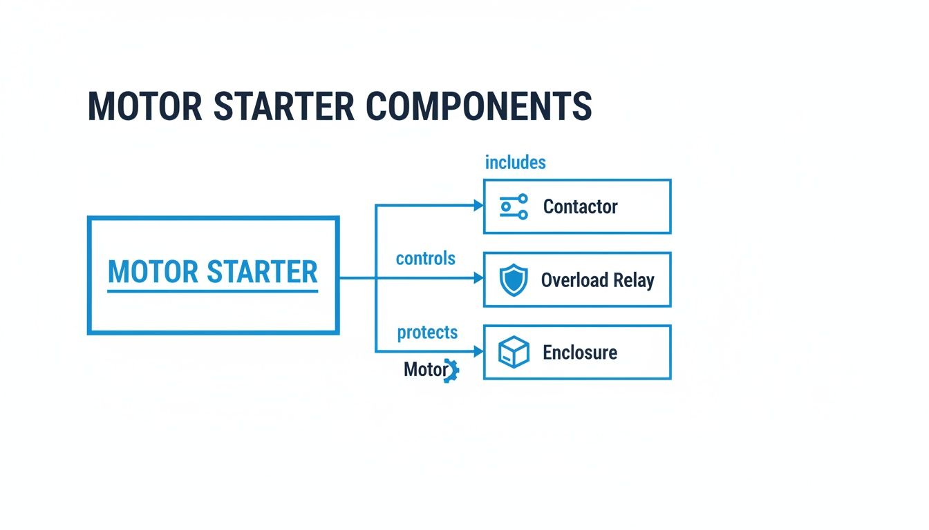
A Look Inside the Box: The Key Components of a Motor Starter
A motor starter might just look like another gray box on the wall, but pop the cover, and you'll find a team of specialized components working in concert to wrangle some serious electrical power. Once you know what these parts do, the starter stops being a mystery and becomes a logical, effective system. Think of it like looking under the hood of a car—every part has a specific and critical job to do.
At the heart of it all, you have two main players: the contactor and the overload relay. This duo is the core of the starter, handling both the control and the protection. Everything else in that enclosure is there to support them in their mission to safely manage your motor.
The Contactor: The Heavy-Duty Switch
Ever tried to power a massive industrial fan with a standard light switch? You’d get a spectacular pop, a bit of smoke, and a melted switch. That’s because a regular switch just can't handle the massive inrush of electricity. That's exactly where the contactor steps in. It's a beefy, heavy-duty switch built specifically to handle the high currents motors need to get going and stay running.
When an operator hits the "start" button, a small control signal energizes an electromagnetic coil inside the contactor. This creates a powerful magnetic field that slams a set of large electrical contacts shut, completing the high-power circuit and sending the juice to the motor.
Function: To safely connect and disconnect the motor from its main power source.
Mechanism: It uses a small electromagnetic coil to open and close a set of much larger, high-power contacts.
Analogy: It’s the bouncer at a nightclub door. It only opens the door for the huge crowd (the current) when the manager (the operator) gives the signal.
When the "stop" button is pushed, the coil loses its power, the magnetic field collapses, and heavy-duty springs instantly snap the contacts apart, cutting power to the motor safely and decisively.
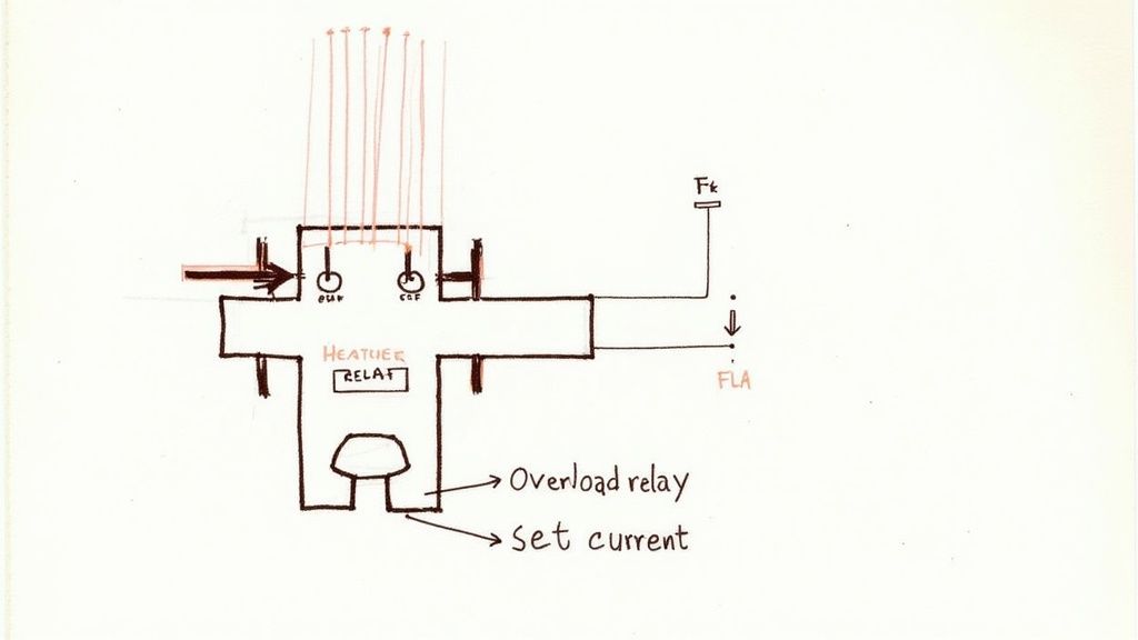
The Overload Relay: The Motor's Bodyguard
If the contactor provides the muscle, the overload relay is the vigilant bodyguard. Its entire purpose is to protect the motor from its greatest enemy: too much current over time. A motor that draws excessive current starts to overheat, which will quickly cook the insulation on its internal windings and lead to a complete, and often catastrophic, failure.
An overload isn't a dead short—it's more of a slow burn. It's a sustained period of high current draw, often caused by something like a mechanical jam, failing bearings, or even low supply voltage. The overload relay is always watching, constantly monitoring the current flowing to the motor. If it sees a dangerously high level for too long, it "trips."
Here's the key part: The overload relay doesn't actually cut the main power to the motor itself. Instead, it opens a tiny contact in the control circuit, which kills power to the contactor's coil. The contactor then does the heavy lifting, opening its main contacts and shutting down the motor. This indirect action is a brilliant and fundamental safety feature.
This protective role is so vital that a contactor without an overload relay isn't a motor starter at all—it's just a simple switch. To really get into the weeds on this, check out our guide on the fundamentals of the protection of motors to see how all these pieces fit into the bigger picture of motor longevity.
Types of Overload Relays
Overload relays generally come in two flavors, each using a different trick to spot an overcurrent.
Thermal Overload Relays: These are the old-school, tried-and-true workhorses. They use a bimetallic strip that heats up as current flows through it. If too much current flows for too long, the strip gets hot, bends, and physically trips a switch that interrupts the control circuit. They’re simple, tough, and get the job done without breaking the bank.
Electronic (Solid-State) Overload Relays: The modern approach. These relays use current transformers for hyper-accurate current measurement. They give you a much wider range of settings, faster trip times, and can even include extra features like phase loss detection. They're the go-to choice for protecting more expensive motors or for applications where downtime is not an option.
The Supporting Cast
Beyond the big two, a few other components play essential supporting roles inside the starter enclosure.
Control Transformer: The motor itself might be running on 480V, but the control circuit with the pushbuttons and contactor coil often uses a much safer, lower voltage like 120V or 24V. A control transformer is there to step down the main voltage to power these components safely.
Pilot Lights and Pushbuttons: This is how humans interact with the machine. Green and red lights (pilot lights) give you a clear visual on the motor's status (running or stopped). Pushbuttons provide the simple start, stop, and sometimes jog or reverse commands.
Enclosure: This is the steel box that keeps all the important stuff inside safe from the outside world—whether that’s dust in a woodshop or corrosive wash-downs in a food processing plant.
Put them all together, and you have a seamless system that delivers both precise control and rock-solid protection, keeping your motors running safely and reliably, day in and day out.
Comparing the Different Types of Motor Starters
Picking the right motor starter is a lot like choosing the right tool for the job. You wouldn't use a sledgehammer to tap in a finishing nail, right? In the same way, the simple starter that's perfect for a small workshop grinder is completely wrong for a massive industrial pump.
Each type of starter strikes a different balance between cost, complexity, and control. Getting this choice right is fundamental to protecting your equipment, keeping things running efficiently, and staying on budget. Let’s break down the main categories, starting with the most basic and working our way up.
The Foundational Choice: Across-the-Line Starters
The Across-the-Line (ATL) starter is the most straightforward and common type you'll find. It's often called a Direct-On-Line (DOL) starter, and you can think of it as a heavy-duty light switch. When you hit the "start" button, it slams the motor with full line voltage, instantly delivering 100% of its starting torque.
This direct approach is both its greatest strength and its biggest weakness. For smaller motors—usually under 10 horsepower—it's simple, cheap, and incredibly reliable. But that massive jolt of power draws an inrush current that can be six to eight times the motor's normal running current. On a big motor, that surge can cause voltage to sag across your entire facility and puts brutal mechanical stress on couplings, belts, and gearboxes.
Stepping Up: Reduced-Voltage Starters
When the electrical and mechanical shock from an ATL starter is just too much to handle, a Reduced-Voltage Starter is the next logical step up. The whole idea is to soften the blow by starting the motor with less voltage and then switching to full power once it gets spinning.
One of the most common ways to do this is with a Star-Delta (or Wye-Delta) starter.
How It Works: This is a clever trick of temporarily rewiring the motor's internal connections. During startup, it uses a "star" (or wye) configuration, which drops the voltage across each winding to about 58% of the full line voltage.
The Result: This simple change slashes both the starting current and torque down to about one-third of what a direct start would produce. Once the motor is up to speed, a timer flips the connections over to the standard "delta" configuration for full-power operation.
It’s a cost-effective way to get a smoother start for medium-sized motors, making it a popular choice where you need to reduce the initial jolt but don't need pinpoint control.
This diagram shows the core components that make these electromechanical starters tick.
As you can see, the contactor and overload relay do all the heavy lifting, all packaged safely inside an enclosure.
The Modern Era: Solid-State Soft Starters
Now we're getting into electronic control with the Solid-State Soft Starter. Unlike the clunky, stepped approach of a Star-Delta, a soft starter gives you a perfectly smooth, linear ramp-up of voltage. It uses electronics called SCRs to precisely "chop" the AC waveform, gradually feeding more power to the motor over a time you can set.
A soft starter is like gently pressing the accelerator in a car instead of stomping on it. The result is an exceptionally smooth, jolt-free start that minimizes both electrical and mechanical stress on the entire system.
This controlled acceleration is perfect for things like conveyor belts, where a sudden start would send products flying, or in pumping systems, where it eliminates the damaging "water hammer" effect. Many soft starters also include a soft stop, ramping the voltage down for an equally smooth shutdown.
The Ultimate Solution: Variable Frequency Drives
At the very top of the performance pyramid is the Variable Frequency Drive (VFD), sometimes called an inverter. A VFD isn't just a starter; it’s a complete motor control system. It takes the incoming AC power, converts it to DC, and then uses that to build a brand new AC output where both the voltage and frequency are completely adjustable.
By controlling the frequency, a VFD gives you precise control over the motor's speed at all times. This is an absolute game-changer for countless industrial processes.
Total Control: You can set exact acceleration and deceleration ramps, control torque, and change the motor's running speed on the fly.
Energy Savings: For equipment with variable loads, like fans and pumps, a VFD can slash energy bills. By matching motor speed to the actual demand, the savings are huge. Slowing a fan by just 20% can cut its energy use by nearly 50%.
Advanced Functionality: VFDs handle reversing, dynamic braking, and provide a ton of diagnostic feedback, making them the most versatile and powerful motor control solution out there.
While they cost more upfront, the gains in process control and energy efficiency often deliver a quick return on that investment, making them the gold standard for motor control.
Comparison of Motor Starter Technologies
To make the choice clearer, it helps to see these technologies compared side-by-side. Each has a distinct role, and what’s best really depends on the application's demands for control, protection, and efficiency.
Feature
Across-the-Line Starter
Soft Starter
Variable Frequency Drive (VFD)
Starting Method
Full voltage, instantaneous
Gradual voltage ramp-up
Full control of both frequency and voltage
Starting Current
Very high (6-8x full load amps)
Reduced (1.5-4x full load amps)
Fully adjustable, typically limited to 1.5x full load amps
Mechanical Stress
High
Low
Very low
Speed Control
None
None (only controls start/stop)
Full and precise speed control during operation
Energy Savings
None
Minimal (only during startup)
Significant, especially on variable-torque loads (fans, pumps)
Complexity & Cost
Low cost, simple
Moderate cost and complexity
Highest cost and complexity
Best For
Small motors (<10 HP), applications where high torque is needed instantly
Conveyors, pumps, fans, and any application where a smooth start is critical
Applications requiring precise speed control, and maximum energy efficiency
Ultimately, the journey from a simple ATL starter to a sophisticated VFD reflects the evolution of industrial control. Knowing where your application fits on this spectrum is the first step toward a more reliable and efficient operation.
How to Correctly Select and Size a Motor Starter
Choosing the right motor starter isn’t about guesswork. It’s a methodical process, and getting it wrong can be costly. A mismatched starter is a direct path to nuisance tripping, premature equipment failure, and some serious safety hazards.
Think of it like picking a circuit breaker for your house. Too small, and it trips all the time. Too big, and it fails to protect your wiring from a potential fire. The same logic applies here, just with much higher stakes in an industrial setting.
The whole process starts with one single source of truth: the motor’s nameplate. That little metal plate has every critical piece of data you need to make the right call.
Decoding the Motor Nameplate
Your journey to finding the perfect starter begins by grabbing three key details right off the motor you’re working with. These are the non-negotiables that will steer every decision you make from here on out.
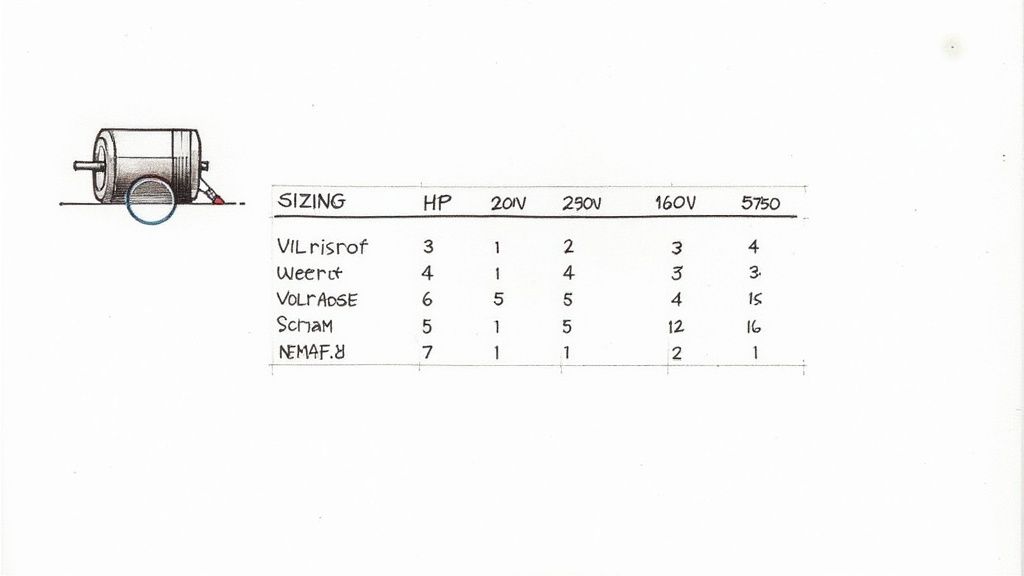
Horsepower (HP): This is the classic measure of a motor's power. Most starter selection charts are organized by horsepower, making it your first point of reference.
Full Load Amps (FLA): This number tells you the maximum current the motor will draw when it's working at its rated load. The overload relay inside the starter has to be set based on this value for proper protection.
Service Factor (SF): Usually a number like 1.15 or 1.25, the service factor tells you how much of an overload the motor can handle for short bursts without being damaged. For example, a 10 HP motor with a 1.15 SF can safely run at 11.5 HP for a limited time. This is absolutely critical for sizing your overload protection correctly.
Without these three values, you’re basically flying blind.
Navigating Sizing Standards
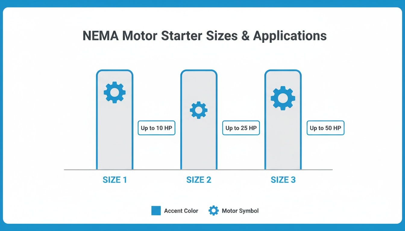
Once you have your motor data, it's time to match it to a starter using one of the industry's sizing systems. In North America, the standard to know is from the National Electrical Manufacturers Association (NEMA). NEMA starters are the tanks of the industry—robust, heavy-duty, and built around a simple sizing chart.
NEMA sizes are designated by numbers (like NEMA Size 0, Size 1, or Size 2), and each one corresponds to a specific horsepower rating at different voltages. For example, a NEMA Size 1 starter is a solid choice for a 10 HP motor running on 480V. It's a straightforward system that makes selection pretty easy. You can use a detailed NEMA motor starter sizing chart to break down the ratings by voltage and motor size.
Properly selecting and sizing a motor starter is a critical step in mitigating potential electrical and mechanical hazards, forming a key part of any comprehensive risk assessment process. Understanding these standards is fundamental to building a safe and compliant system. For a broader look at this topic, you can review guidelines on conducting a thorough risk assessment process.
The other major player is the International Electrotechnical Commission (IEC). IEC starters are generally more compact and budget-friendly, and they offer more specific sizing options. The trade-off? They’re less forgiving of overloads compared to their NEMA cousins, so you need to be much more precise with your selection.
Choosing the Right Enclosure
The final piece of the puzzle is the enclosure. You have to shield the starter’s guts from its operating environment to keep it running safely and for a long time. NEMA has a clear rating system for enclosures that tells you exactly what kind of protection you're getting.
Here are a few of the most common ones you'll run into:
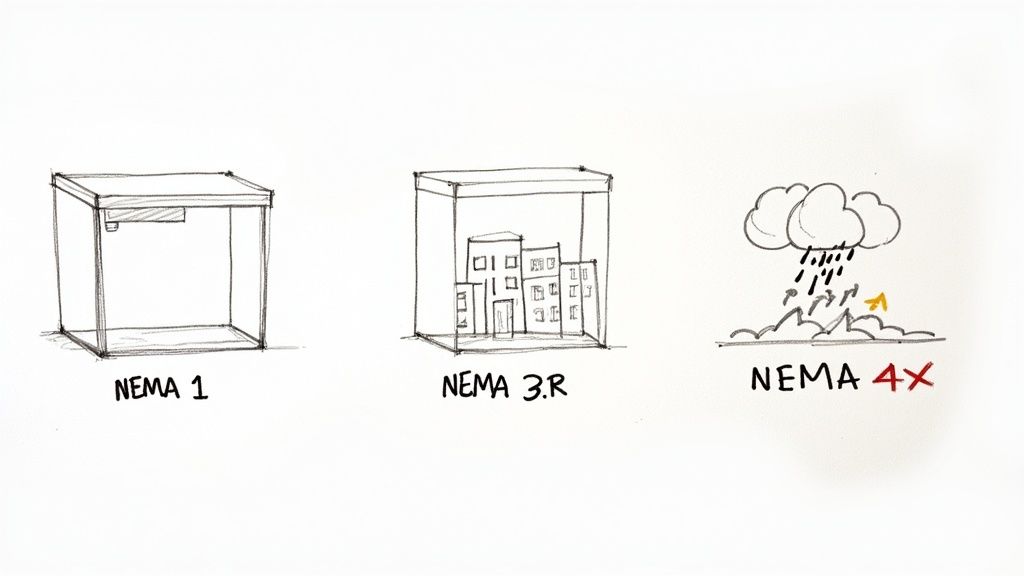
NEMA 1: This is your basic, general-purpose indoor enclosure for clean, dry locations. It keeps fingers out but won't do much against dust or water.
NEMA 3R: Built for the outdoors, this enclosure protects against rain, sleet, and snow.
NEMA 4X: When you need serious protection, this is it. It’s watertight, dust-tight, and corrosion-resistant, making it the go-to for washdown areas in food plants or salty marine air.
NEMA 12: Designed for indoor industrial environments, it protects against things like circulating dust, falling dirt, and non-corrosive drips.
By carefully matching your motor data, the right sizing standard, and the correct enclosure, you can be confident your motor starter will perform safely and reliably for years.
Wiring Fundamentals and Real-World Applications
Knowing the parts of a motor starter is one thing, but seeing how they come together in the real world is where it all starts to make sense. A motor starter isn't just some box of electrical parts; it's the heart of countless machines, from the pump filling a city's water tower to the conveyor zipping packages across a warehouse floor.
The starter you choose has a direct impact on the machine's performance, how long it lasts, and how safe it is to operate. Every application throws a different curveball, and you need the right kind of control to knock it out of the park.
Where You'll Find Motor Starters
Different machines have wildly different needs. A sudden, high-torque start might be exactly what a rock crusher needs, but it would be catastrophic for a delicate pumping system. This is why you can't just pick any starter off the shelf.
Here are a few common places you'll see them and why a specific type gets the job:
Pumps: A soft starter is the go-to choice here. Slamming a pump on at full speed can cause "water hammer"—a destructive pressure spike that rattles pipes and can cause serious damage. A soft starter gently ramps up the motor, avoiding that mechanical shock and making the whole plumbing system last longer.
Fans and Blowers: For a simple exhaust fan, a basic across-the-line starter usually does the trick. But if you need to vary the airflow, a VFD is the way to go. It gives you pinpoint speed control and can lead to massive energy savings.
Conveyors: Just like with pumps, conveyors love a smooth start. A soft starter prevents products from lurching forward, falling over, or getting damaged. It gets the belt moving with a gentle, controlled acceleration.
Compressors: These often need a huge kick of torque to get going against the pressure already in the system. In these situations, a direct-on-line (DOL) starter delivers that instant jolt of power to get the compressor up and running fast.
Cracking the Code on the Wiring
At first glance, the wiring inside a starter can look like a bowl of spaghetti. But it’s all built on a brilliantly simple idea: keep the high-power "muscle" separate from the low-power "brains." Every starter has two circuits that work in tandem.
1. The Power Circuit: This is the heavy-hitter. We're talking thick, heavy-gauge wires carrying the full motor current—often 480 volts or more. This circuit runs from the main power source, through the beefy contacts in the contactor, and straight to the motor. It’s the part that does all the real work.
2. The Control Circuit: This is the smart, low-voltage side of the operation. It typically runs on a much safer voltage like 120V AC or 24V DC. This circuit includes the pushbuttons, the coil for the contactor, and the overload relay contacts. Its only job is to tell the power circuit when to turn on and off.
This separation is a core principle of industrial safety and design. It lets an operator safely control a massive, high-horsepower motor with a simple, low-energy pushbutton.
The Simple Genius of 3-Wire Control
One of the most common and vital wiring schemes you'll encounter is called 3-wire control. This setup uses a momentary "start" button and a momentary "stop" button to run the motor, but it has a crucial safety feature built right in: it prevents a machine from restarting by itself after a power outage.
Key Takeaway: With 3-wire control, if the power goes out while a machine is running, it will not automatically fire back up when the power returns. An operator has to physically walk over and press the "start" button again, ensuring the machine only runs when someone is present and ready for it.
This elegant, simple logic is a cornerstone of machine safety in just about every factory and plant. To see how these ideas play out in practice, you can dive into our guide on a three-phase motor wiring diagram. It’s the next step in bridging the gap between knowing what a motor starter is and understanding how to put one to work safely and effectively.
Your Top Motor Starter Questions, Answered
Even after getting the basics down, you're bound to run into specific questions when you're in the thick of a project. Whether you're selecting, installing, or troubleshooting a motor starter, a few common queries always pop up.
This section is a quick-hitter guide for engineers and techs on the floor. We'll cut through the noise and give you direct answers on the differences between similar components, using advanced starters, and what to do when a starter trips. Think of it as a cheat sheet to build on what you already know.
What’s the Real Difference Between a Contactor and a Motor Starter?
This is easily the most common point of confusion, but the distinction is dead simple and absolutely critical for safety. The easiest way to think about it is that a motor starter is a complete system, and a contactor is just one piece of that system.
A contactor is nothing more than a beefed-up switch. Its only job is to open and close a circuit to connect or disconnect the motor from its power source. It gives you control, but it offers zero protection against overcurrents that can fry a motor in seconds.
A motor starter, on the other hand, bundles that same contactor with an overload relay. That overload relay is the brains of the outfit, constantly watching the current flowing to the motor. If it senses a dangerous overload, it trips and signals the contactor to cut the power.
In short: Every motor starter has a contactor inside, but a contactor alone is not a motor starter. A contactor is for control; a motor starter is for control and protection.
Can I Just Use a VFD as a Motor Starter?
Absolutely. In fact, a Variable Frequency Drive (VFD) is the most sophisticated and capable motor starter you can get. It handles all the core functions—starting, stopping, and built-in overload protection—but it does so much more.
While a basic starter just provides on/off control (and a soft starter just manages the voltage ramp-up), a VFD gives you total command over the motor's speed, torque, and even its direction while it's running. It works by fundamentally changing the frequency of the power it sends to the motor.
A VFD is the ultimate soft start, but its real power is unlocked in applications where you need variable speed for process control or massive energy savings. For example, using a VFD to slow down a fan or pump to match real-time demand can slash electricity use by 30-50% or more.
My Motor Starter Tripped. How Do I Reset It?
Hold on. Before you even think about hitting that reset button, remember this: an overload trip isn't a failure. It's the starter doing its job perfectly, saving your expensive motor from burning up. The first step is always to figure out why it tripped.
Look for common culprits like:
A Mechanical Jam: Is the equipment connected to the motor physically stuck or blocked?
Bad Bearings: Worn-out bearings in the motor or the load can create huge amounts of friction.
Voltage Imbalance: Unstable power from the utility can force the motor to draw excess current.
Sustained Overload: Is the motor simply being asked to do more work than its nameplate rating allows?
Once you've found and fixed the root problem, resetting is usually straightforward. Most overload relays have a prominent reset button, often colored blue or red.
A quick tip: for thermal overloads, you might need to wait a few minutes for the internal bimetallic strip to cool down before it will reset. It's also smart to set the device to "manual reset." This prevents the machine from unexpectedly restarting on its own after an overload, which is a major safety hazard for anyone working on the line.
What Does the “NEMA Size” on a Starter Actually Mean?
NEMA, the National Electrical Manufacturers Association, created a standardized sizing system that’s the go-to standard in North America. This system sorts starters into different "sizes" based on the current and horsepower they can handle at different voltages.
These sizes are numbered, starting from NEMA Size 00 for tiny motors all the way up to NEMA Size 9 for giant industrial equipment. Each size has a maximum horsepower rating. For instance, a NEMA Size 1 starter is generally rated for a 10 HP motor running on 480V.
The biggest advantage of the NEMA system is its sheer toughness and interchangeability. A NEMA Size 1 starter from one brand is built to the same heavy-duty standard as one from another. This makes selection easier and guarantees you're getting a durable workhorse built for demanding environments.
At E & I Sales, we live and breathe motor control. We help engineers and project managers spec the right solutions, from off-the-shelf starters to fully engineered and integrated UL-listed control panels. Our team has the expertise to make sure your systems are safe, efficient, and built to last.
A ground fault test is one of the most important diagnostic tools in your arsenal. It’s how you verify that your electrical insulation is solid and that your safety systems are actually ready to detect dangerous stray currents. This isn't just about ticking a box for compliance; it's often the single most important step in tracking down those maddening intermittent trips and preventing a serious shock or fire.
Why a Ground Fault Test Is Your First Line of Defense
When a machine starts tripping intermittently, the first instinct for many is to start swapping parts—a new breaker here, a different drive there. More often than not, this shotgun approach completely misses the real culprit: a ground fault.
This happens when electrical current leaks out and finds an unintended path to ground. Think of worn insulation on a motor lead rubbing against the inside of a metal conduit. This creates a severe, hidden hazard for both your people and the equipment itself.
The Real Danger of a "Slow Leak"
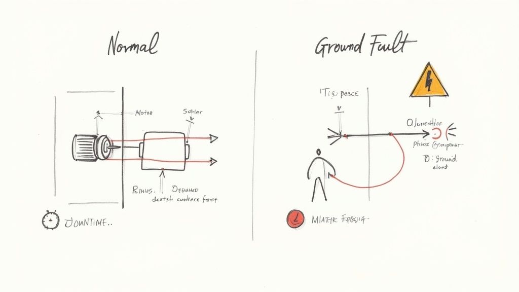
It’s easy to confuse ground faults with short circuits, but they behave very differently. A short circuit is like a head-on collision—two conductors touch, creating a massive, instantaneous current spike that trips a standard breaker immediately. A ground fault, on the other hand, is more like a slow, dangerous leak.
A small amount of current escapes its intended path. It might not be enough to trip a standard overcurrent device, but it's more than enough to deliver a fatal shock.
The true danger is how subtle it can be. Because the fault current is often low, the equipment might keep trying to run, even while its entire metal frame is dangerously energized. Performing a ground fault test is how you find this hidden killer before it causes a catastrophic failure or, worse, a serious injury.
What You Gain From Regular Testing
Making ground fault testing a routine part of your preventative maintenance is fundamental to keeping an electrical system reliable and safe. It helps you:
Prevent Unscheduled Downtime: Finding insulation breakdown early lets you schedule a repair on your own terms, not in the middle of a critical production run.
Protect Expensive Assets: A nagging ground fault can cook the windings on motors and transformers or fry sensitive electronics in control panels.
Ensure Personnel Safety: This is the big one. An undetected ground fault turns a machine into a ticking time bomb. It’s also important to understand broader safety protocols, like the battery and fire-safety considerations for homes and facilities with energy storage systems.
A proactive approach to ground fault testing shifts your entire maintenance posture from a reactive, stressful cycle to a controlled, preventative strategy. It’s the difference between finding a small problem during a planned outage and discovering a major failure during peak production.
Ground Fault vs Short Circuit At a Glance
To be an effective troubleshooter, you need to know the difference between these two common faults. This table breaks it down.
Characteristic
Ground Fault
Short Circuit
Current Path
From a "hot" conductor to an equipment grounding conductor, metal frame, or conduit.
Directly between two or more "hot" conductors (phase-to-phase) or between a hot and a neutral.
Current Level
Can be very low (milliamps) or high, but often below the trip rating of a standard circuit breaker.
Extremely high, typically hundreds or thousands of amps, causing an immediate overcurrent trip.
Primary Hazard
Electric shock. The equipment frame can become energized without any obvious signs of a problem.
Fire and arc flash. The massive energy release can cause explosions and fires.
Knowing which fault you're likely dealing with points you to the right diagnostic tools and safety precautions from the start.
The need for this kind of specialized detection isn't new; engineers have been working on this since the early 20th century. A deeper understanding of modern ground fault protection principles will make your testing and troubleshooting that much more effective.
Assembling Your Toolkit and Safety Gear
Trying to run a ground fault test without the right prep is more than just inefficient—it’s how accidents happen. This is your pre-flight checklist. Success starts long before you ever hook up a test lead, kicking off with a serious commitment to safety and having the right diagnostic gear in hand.
This isn't about just grabbing any old pair of gloves from the truck. Every piece of Personal Protective Equipment (PPE) is your last line of defense against thousands of volts. One simple slip-up can have life-altering consequences, which makes having the right gear absolutely non-negotiable.
Your Non-Negotiable Safety Kit
Before you even think about opening a cabinet, you need to be wearing the right armor. The specific level of PPE you need is determined by an arc flash hazard analysis, but for any industrial ground fault testing, your baseline kit must include:
Voltage-Rated Gloves with Leather Protectors: These are your first and best defense against electric shock. Always, and I mean always, inspect them for pinholes by rolling them up and trapping air inside before each use.
Arc-Rated Clothing or Suit: Your standard work clothes will do absolutely nothing to protect you from the searing heat of an arc flash. Proper FR/AR gear is designed to self-extinguish and can be the difference between a close call and a catastrophic injury.
Safety Glasses and Arc Flash Hood/Face Shield: You only get one set of eyes. An arc flash throws off blindingly bright light and a spray of molten metal, making this protection critical.
Insulated Tools: While they're no substitute for a proper lockout, using tools with a 1000V insulation rating adds a vital layer of protection from an accidental slip.
A quick reminder from the field: PPE doesn't make you invincible. It just gives you a fighting chance if things go sideways. It only works if you use it correctly and keep it in good condition.
Essential Diagnostic Instruments
Once you're geared up for safety, it's time to grab the right tools for the diagnosis. Your standard multimeter is great for quick voltage checks, but it’s the wrong tool for this job. For a real ground fault test, you need specialized equipment.
These are your two workhorses:
Insulation Resistance Tester (Megohmmeter): This is your go-to for checking the health of motor windings and cable insulation. It applies a high DC voltage—typically 500V or 1000V—to stress the insulation and measures the resistance in megohms (MΩ). A low reading means you likely have a leakage path to ground.
Ground Fault Relay Test Set: This device is for testing the protection system itself. It injects a simulated fault current through the system's current transformer (CT) to prove the ground fault relay trips at the right current setting and within the specified time. This is how you confirm the whole system—sensor, relay, and breaker—is working together as it should.
Executing a Lockout/Tagout Procedure
No testing begins until that equipment is at a zero-energy state. A methodical Lockout/Tagout (LOTO) procedure is the only way to be sure.
Let’s walk through a common scenario: isolating a bucket in a 480V Motor Control Center (MCC).
Scenario: Isolating MCC Bucket #7 for a Motor Ground Fault Test
Everything starts with clear communication. Make sure everyone working in the area knows what's about to happen.
The qualified electrician performing the work will then:
Identify the Source: Positively identify the disconnect handle for Bucket #7. Double-check the label.
De-energize: Firmly rack out the bucket or throw the disconnect to the "OFF" position.
Apply Lock and Tag: Place your personal lock and tag on the disconnect. Your tag needs your name, the date, and why it's locked out. And remember, no one else should ever have a key to your lock.
Verify Zero Energy: This is the most crucial step. Using a properly rated multimeter, you have to perform a live-dead-live test. First, test your meter on a known live source to prove it works. Next, test for voltage on the load-side terminals of the bucket (phase-to-phase and each phase-to-ground). Finally, go back and re-test your meter on that same known live source.
Only after you've confirmed zero volts is it safe to proceed. This process guarantees that the circuit can't be re-energized while you’re in the middle of your test.
Testing Insulation Resistance on Motors and Cables
When you're staring down a suspected ground fault, all the theory in the world takes a backseat to what you can prove with a meter in your hand. This is where the insulation resistance test—what most of us in the field just call a "megger" test—becomes your best friend. It’s the single most effective way to get a real health check on a motor’s windings or a run of cable before a nagging problem turns into a catastrophic failure.
Let's put this into a real-world context. Imagine you've got a three-phase, 480V motor that keeps tripping. You’ve done your Lockout/Tagout, you’ve verified zero energy, and now it's time to find out what's really going on.
The Motor Test Procedure
The tool for this job is an insulation resistance tester, or megohmmeter. The whole point of the test is to push a specific DC voltage into the motor's windings and measure how much of that current "leaks" through the insulation to the grounded frame of the motor. A high resistance reading means healthy insulation. A low reading? That’s your red flag.
First things first, you have to get the motor completely on its own. It's not enough to just lock out the breaker; you need to physically disconnect the motor leads from the starter or VFD. We need to test the motor by itself, not the whole circuit.
Once you're at the motor's junction box (the peckerhead), here’s the game plan:
Pop open the cover and disconnect the incoming T1, T2, and T3 leads from the motor's own leads.
Make absolutely sure the motor leads are spread apart, not touching each other or any part of the metal housing.
Clip one lead from your megohmmeter right onto the motor's frame. Find a clean, unpainted bolt head—that makes a perfect ground reference.
Take your other test lead and connect it to all three motor windings (T1, T2, and T3) at the same time. A few alligator clips make it easy to jumper them all together for this part of the test.
With this setup, you're checking the integrity of the entire winding assembly against its grounded enclosure. You're hunting for any sneaky path electricity might be taking to ground where it shouldn't be.
Selecting the Right Test Voltage
Picking the right voltage on your megger is crucial. Go too high, and you risk damaging perfectly good insulation. Go too low, and you won’t put enough stress on it to reveal a hidden weakness.
A good rule of thumb is to test at about double the circuit's operating voltage, but we stick to standard practices:
For 480V or 600V systems, you’ll almost always use the 1000V DC setting.
For smaller circuits under 250V, a 500V DC test is the way to go.
For our 480V motor, set the meter to 1000V DC and hit the test button. You need to hold it for a full 60 seconds. You'll likely see the resistance reading climb as the windings get charged up—that's normal. The number you care about is the final, steady reading at the one-minute mark.
So, what’s a "good" number? While standards from groups like NETA give you the official specs, a reliable field rule is 1 megohm per kV of the motor's rating, plus another 1 megohm. For a 480V (0.48kV) motor, that means anything over 1.5 MΩ is generally considered a pass. Honestly, though, a healthy modern motor should give you a reading way up in the hundreds or even thousands of megohms.
Applying the Same Logic to Power Cables
If the motor tests out clean, your next suspect is the cable feeding it. Thankfully, the process is pretty much the same. With the cable disconnected on both ends (at the MCC and the motor), you’ll test the insulation of each conductor.
Here's how you break down the cable test:
Phase-to-Ground: Test each conductor one by one. Hook one meter lead to the ground wire or conduit, then test Phase A, then Phase B, then Phase C with the other lead.
Phase-to-Phase: Now, check for shorts between the conductors themselves. Test A-to-B, B-to-C, and finally A-to-C.
This thorough check confirms the cable's integrity from end to end. If you get a low reading here, you're likely dealing with insulation that's been pinched in a conduit, damaged by moisture, or just cooked from years of heat. Diving deeper into these scenarios is key, which is why we put together a guide on the protection of motors that covers more ground.
This kind of hands-on insulation testing is so important because many ground faults, especially high-impedance faults (HIFs), simply don't draw enough current to trip a standard breaker. Research has shown a 240V fault through just 1 kΩ of resistance only produces about 240 mA of current—nowhere near enough for most overcurrent devices to even notice. That's why a megohmmeter is the only tool that can reliably sniff out these dangerous, hidden faults before they cause real damage.
How to Performance Test Your Protection System
An insulation resistance test is a great diagnostic tool. It tells you a lot about the health of individual components, like motor windings or cables. But here’s what it doesn't do: it doesn't prove that your entire safety system—the relay, the sensor, and the breaker—will actually work together to clear a fault when it matters most.
That's where a true performance ground fault test comes in. This is the crucial step that moves beyond checking component health to verifying total system function.
This isn’t just a nice-to-have; it's a code requirement. According to NEC Section 230‑95, every ground‑fault protective device must be performance-tested when it's first installed on-site. You also need a written record of that test available for the authority having jurisdiction (AHJ). The code is specific, calling for injected current tests—not just a quick push-button check—to verify the system's actual pickup current and trip time.
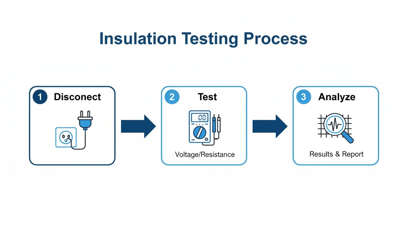
The general process follows a simple, methodical flow: safely isolate the equipment, run the test, and then analyze the results to make an informed decision.
This visual really drives home the core steps. You always start by disconnecting and verifying a zero-energy state. Only then do you apply the test, and finally, you interpret the data you've gathered.
Choosing the Right Ground Fault Test Method
There are a few ways to approach ground fault testing, and picking the right one depends on what you need to verify. Each method has its place, offering a different level of assurance.
This table breaks down the common methods to help you understand their best applications, what they can tell you, and just as importantly, what they can't.
Test Method
Primary Application
Pros
Cons
Push-to-Test Button
Simple go/no-go verification of the relay and trip coil.
Quick and easy; requires no special equipment.
Doesn't test the CT or wiring; doesn't verify pickup or timing accuracy.
Secondary Injection
Verifies relay pickup settings and timing curves.
Highly accurate for testing the relay's logic and calibration.
Bypasses the main current transformer (CT) and its wiring.
Primary Injection
Full system performance test, from the CT to the breaker.
Tests the entire protection chain; the most comprehensive and reliable method.
Requires specialized high-current test set; more time-consuming to set up.
While a push-to-test is a decent spot check, the primary injection method is the gold standard for commissioning and thorough maintenance because it leaves no part of the system unverified.
Setting Up for Primary Current Injection
We're going to focus on the primary injection method because it’s the most thorough way to test a ground fault protection relay in switchgear. This technique uses a high-current test set to push a simulated fault current right through the system's zero-sequence current transformer (CT). It’s the only way to test the entire chain of command, from the CT's ability to sense the fault to the relay's logic and the breaker's physical trip mechanism.
First thing's first: safety. Completely isolate the circuit breaker or switchgear section you're testing. Meticulously follow your LOTO procedure, making sure the equipment is de-energized and verified at a zero-energy state. You'll be working with a test set that can produce thousands of amps, so there's no room for error.
Once the equipment is safely isolated, it's time to connect the high-current test set. The connections are fairly simple but demand precision.
Connect the high-current output leads from your test set so they pass directly through the window of the zero-sequence CT.
The timer input leads from your test set will connect to the breaker’s auxiliary contacts. This is how the test set automatically records the time it takes for the breaker to open after the relay issues its trip command.
This setup creates a controlled, closed loop that perfectly mimics a real-world ground fault, letting you measure the system's actual response.
Calculating Your Test Parameters
Before you inject a single amp, you need to know what you're looking for. The target values for your test are right there on the ground fault relay itself—either on the faceplate dials or within its programming file. You need to find two key settings: the pickup current and the time delay.
Let's walk through a common scenario. Imagine a relay is set for a 100A pickup with a time delay of 0.1 seconds (100 milliseconds).
With these settings, your test needs to verify two things:
Pickup: What is the minimum current that makes the relay operate?
Timing: How long does it take for the breaker to trip at a specific, higher fault current (usually 300% of the pickup setting)?
To check the pickup value, you’ll start injecting current well below the 100A setting and slowly ramp it up. The exact amperage where the relay's "pickup" light comes on is your measured value. It should be right on the money, very close to that 100A setting.
Executing the Test and Verifying Trip Time
Once you've confirmed the pickup value, it's time to check the trip time. This is where you test the system’s reaction speed. Based on the coordination settings, you’ll inject a higher current—a standard practice is to use three times the pickup setting—to simulate a more serious fault.
In our example, that means injecting 300A.
The test set will apply 300A and start its timer at the same instant. The moment the breaker trips, its auxiliary contacts open, which stops the timer. The time displayed is your measured trip time. For our relay set to 0.1 seconds, seeing a result between 95-105 milliseconds would be a solid pass.
The real value of this test is in the data. Documenting the "as-found" settings, the measured pickup current, and the measured trip time creates a baseline for all future maintenance. This record is your proof of compliance and your best tool for tracking the health of your protection system over time.
By comparing these real-world results to the manufacturer's specs and your own coordination study, you'll know everything you need to. If the values are within tolerance, your system is good to go. If not, it's time to start troubleshooting the relay, CT, or breaker before that circuit goes back into service.
Interpreting Results and Troubleshooting Faults
A failed ground fault test isn't a dead end—it's a signpost pointing you toward the real problem. The readings on your meter are clues, and learning how to interpret them is what separates a parts-swapper from a true diagnostician. A low megohm reading or a relay that won't trip is simply the start of a logical troubleshooting process.
This is where you put on your detective hat. The key is to isolate variables systematically. Don’t just assume; prove it with your meter. By breaking a circuit down into its individual components—the cable, the motor, the switchgear—you can pinpoint the exact location of the failure without any guesswork.
The Divide and Conquer Strategy
Let's walk through a common scenario. You run an insulation resistance test on a motor circuit and get a dismal 0.5 MΩ reading. It’s a clear failure. Panic doesn't fix anything, but a solid plan will. The first question is always the simplest: is the problem in the wiring or in the motor itself?
To find out, you need to split the circuit. Get down to the motor's junction box, disconnect the motor leads from the incoming power cable, and then test each piece on its own.
Test the Cable First: With the motor completely out of the circuit, perform the same phase-to-ground insulation test on just the cable. If that reading is still low, you know the fault is somewhere between the starter and the motor j-box.
Then Test the Motor: If the cable tests perfectly (showing hundreds or even thousands of megohms), the fault is almost certainly inside the motor windings.
This simple "divide and conquer" method can save you countless hours of frustration. You've just narrowed a potentially facility-wide headache down to either a specific cable run or a single piece of equipment.
Common Culprits Behind Low Insulation Readings
When an insulation test fails, the root cause is usually some kind of physical damage or contamination. Insulation doesn't just decide to fail on its own; something external causes it to break down.
Here are the usual suspects I look for first:
Moisture Intrusion: Water is electricity’s worst enemy, hands down. A flooded conduit, a leaky seal on a motor peckerhead, or condensation inside a panel are all frequent sources of ground faults.
Heat Damage: Over time, excessive heat from an overloaded motor or just high ambient temperatures can cook insulation until it's brittle. Once it cracks, you've got a ready-made path to ground.
Physical Damage: This is incredibly common, especially during installation. A cable jacket gets nicked while being pulled through a tight conduit, or constant vibration causes a wire to rub against a sharp metal edge inside a panel.
Contamination: In dirty industrial environments, conductive dust from metal grinding or other processes can build up inside equipment, creating a low-resistance path where there shouldn't be one.
A failed test result is just data. The real skill is connecting that data to a physical cause. An intermittent fault that only pops up on rainy days, for instance, is a huge clue that you should be hunting for moisture.
Troubleshooting Failed Relay Performance Tests
So what happens if your insulation tests pass with flying colors, but the ground fault relay itself fails its performance test? This tells you the issue is within the protection system, not the power circuit. If that relay trips too soon, too late, or not at all, your focus needs to shift from insulation to instrumentation.
First things first, double-check the obvious. Are the relay settings correct according to the coordination study? It’s surprisingly common to find that someone programmed the wrong pickup or time delay settings into the device.
If the settings are right, the problem likely lies in the sensing circuit.
Check the CT Wiring: A loose or incorrect connection at the zero-sequence current transformer (CT) is a classic culprit. The relay can't react to a fault it can't see.
Inspect the CT Itself: While rare, current transformers can fail. A damaged or shorted CT simply won't produce the correct secondary current needed to operate the relay.
Understanding these failure modes is crucial for building a complete picture of electrical safety. Sometimes, a persistent ground fault can also be a symptom of a larger issue, which is why it's helpful to understand the various reasons what can cause a breaker to trip beyond a simple fault. After you diagnose and repair the root cause, always re-run your ground fault test to verify the fix before you even think about re-energizing the equipment.
Got Questions About Ground Fault Testing? We've Got Answers.
Even for seasoned pros, a few questions always seem to come up out in the field. Ground fault testing can feel complicated, but once you nail down a few key concepts, you'll have the confidence to get it done right—and safely—every time.
Let's dig into some of the most common questions we hear from technicians and engineers on the floor.
How Often Should I Be Running a Ground Fault Test?
There’s no single, universal answer here. How often you test really boils down to your specific compliance needs and the kind of environment your equipment lives in. But we can map out some solid guidelines that cover most industrial scenarios.
For anything brand new, the rules are black and white. The National Electrical Code (NEC) requires a full performance test on any new ground fault protection system right after it's installed. After that, it becomes a part of your regular preventative maintenance cycle.
For Compliance: The NEC mandates a performance test on initial installation. No exceptions.
For General Maintenance: Following NETA standards is a great baseline. They recommend comprehensive testing every one to three years for most gear.
For Harsh Environments: If your facility deals with high moisture, constant vibration, or conductive dust, don't wait three years. Testing your critical motors and switchgear annually is a smart move that prevents nasty surprises.
What's the Difference Between a GFCI Test and a Ground Fault System Test?
This is a great question because it gets to the heart of a major difference in scale and purpose. They both involve "ground faults," but they are protecting completely different things at wildly different levels.
A GFCI test is a simple life-safety check for a single device, like an outlet near a sink. When you push that little "Test" button, you're just making sure its internal trip mechanism works at a very low leakage current—we're talking just 4-6 milliamperes (mA). It’s all about protecting a person from getting a dangerous shock.
A ground fault system test, on the other hand, is a full-blown diagnostic for your industrial power system. This is a much bigger deal, requiring a proper lockout/tagout and specialized gear like megohmmeters and high-current test sets. The goal here is to confirm the insulation on motors and cables is solid and to prove that your big protective relays will actually trip under massive fault currents to prevent catastrophic equipment damage and fires.
Here’s a simple way to think about it: A GFCI test is like checking the smoke detector in your kitchen. A ground fault system test is like the fire department coming out to test the hydrants and sprinklers for the whole industrial park. Both are critical, but they operate on totally different scales.
Can I Just Use a Multimeter for a Ground Fault Test?
Absolutely not. This is one of the most common and dangerous mistakes we see people make. A standard multimeter is simply the wrong tool for this job; it can't give you the information you actually need.
Your multimeter uses a tiny voltage—maybe just a few volts—to check for things like continuity. It’s perfect for telling you if a fuse is blown, but it's useless for stress-testing insulation. The problem is, insulation often only breaks down when it's hit with a voltage close to what it sees during normal operation.
To do a real ground fault test, you need a proper insulation resistance tester, which most of us just call a megohmmeter. This tool doesn't mess around. It applies a high DC voltage, typically 500V or 1000V, to the conductor. That's enough to properly stress the insulation and reveal any hidden weak spots or leakage paths a multimeter would miss a hundred times out of a hundred. The result is a reading in megohms (MΩ), which is the only true measure of insulation health.
At E & I Sales, we've been designing, building, and troubleshooting complex industrial electrical systems since 1974. Whether you need rock-solid UL-listed control panels, premium motors, or expert system integration, our team has the hands-on experience to deliver the right solution. See how our expertise can power your next project at https://eandisales.com.
Selecting the right coil voltage and matching it to your control circuit can shave hours off panel build time. Below, you’ll find voltage ratings, AC vs. DC options, and essential safety checks in a single glance.
Shunt trip coils range from 12 VDC all the way up to 525 VAC, fitting everything from PLC outputs to heavy industrial emergency stops. (Learn more about shunt-trip coils on literature.rockwellautomation.com)
This simple addition to a molded-case breaker lets you trigger a trip remotely with an external voltage. Get your coil right, and you’ve already solved half the puzzle.
Common Shunt Coil Voltages And Applications
Before you grab your wire cutters, double-check that the coil voltage matches your control supply. Use the table below to see which voltages and applications pair together most often.
Coil Voltage
Control Voltage Type
Typical Use
12 VDC
DC
PLC Outputs
24 VDC
DC
Safety Relays
120 VAC
AC
Motor Shunt Trips
240 VAC
AC
Emergency Stops
Keep this chart handy to avoid last-minute surprises in the field.
Safety Checks And Upstream Protection
Never power a shunt-trip coil without its own control fuse. A small fuse per NEC 240.4 plus correctly sized conductors prevent coil burnout—and eliminate annoying nuisance trips.
Protect the control circuit according to local code to keep the system both safe and reliable.
For AC coils (120 VAC or 240 VAC), tie into a local relay or a PLC output
For DC coils (24 VDC or 48 VDC), add a flyback diode and size your fuse to handle inrush
Example Control Panel Scenario
Picture a packaging line emergency-stop loop driven by a 24 VDC shunt trip. A PLC SINK output energizes the coil through a 1 A fuse, while a flyback diode tames voltage spikes.
You’ll need:
A PLC output rated for your coil’s inrush and steady-state current
A control transformer sized for coil pickup
A thermal-magnetic fuse or mini-breaker per OEM guidelines
Clear routing, consistent wire colors, and these upfront checks cut wiring errors—and slash commissioning time.
This overview sets the stage for detailed schematics and advanced configurations. Next, we’ll dig into coil inrush vs. steady currents so you can size fuses and transformers with confidence.
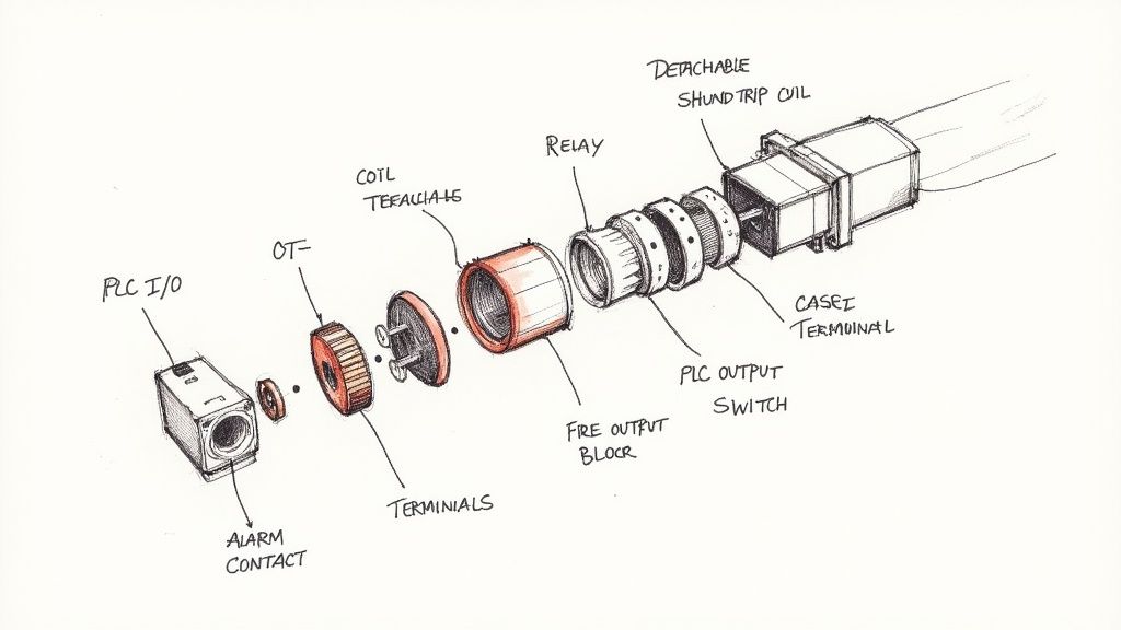
Understanding Shunt Trip Components
Inside a control panel, remote shutdown hinges on two paired parts: the molded-case breaker and its shunt-trip coil. The breaker carries the main load, snaps into a UL-approved footprint, and needs the correct amperage rating to handle both the line and any accessory trip unit.
The shunt-trip coil clips onto the breaker side, offering two control-voltage terminals and a spring-release mechanism that pops the breaker open in an instant.
Most setups rely on a small relay or a PLC output to energize that coil. For cleaner wiring and less interference, I usually mount these components right by the door hinge—shorter runs, quieter operation, and faster troubleshooting.
“A tidy panel makes troubleshooting much faster,” notes a veteran packager who’s wrestled with cramped cabinets.
Key Safety Integrations
When an emergency hits, shunt-trip breakers link directly into life-safety systems. Fire-alarm panels, gas-detection interlocks, and e-stop loops all send a signal to the coil, instantly cutting power.
Fire alarm tie-ins on non-life-safety loads
Gas detection shutdowns in processing lines
Emergency-stop loops on automated packaging equipment
For deeper reading, see Wikipedia. Getting conductor sizes right and picking the proper breaker ensures you meet both NEC and UL standards.
Terminal Connections And Wiring Paths
You’ll find the coil lugs right beside the line and load terminals on the breaker frame—mark them clearly in your wiring diagram. A simple color-code and neat labels will speed up commissioning and prevent miswires.
Map out the common and normally-open coil terminals
Route control wires back to your relay or PLC output
Protect the coil with a fuse sized for its inrush and steady-state current
Device
Control Voltage
Coil Current
Relay
24 VDC
150 mA
PLC
120 VAC
80 mA
I always bundle coil conductors separately from the power feeders to cut down on electromagnetic interference. Check out our ABB molded-case breaker guide for panel integration.
Always test coil activation under nominal voltage before applying power to the main circuit.
Best Practices You Need To Know
Match coil voltage exactly to eliminate extra transformers or relays
Tag both coil leads with ID labels at each termination
Position the control fuse within 12 inches of the breaker per NEC 240.4
With these checks in place, wiring a shunt-trip breaker goes from guesswork to routine. Next up, we’ll dig into inrush currents and transformer sizing so your fuse choices stay rock-solid. Remember to document every connection in your panel drawings and keep your schematics updated with clear revision dates.
Happy wiring always!
Designing Reliable Control Circuits
Nothing’s more frustrating than a control circuit that trips when it shouldn’t—yet refuses to trip when it must. Delivering the right coil voltage under both inrush and steady‐state conditions sets the stage for rock‐solid performance. Overlook transformer sizing or fuse selection, and you’ll wrestle with brownouts or no-trip failures.
OEM datasheets usually save you the legwork, listing coil voltages, torque specs and protective fuse recommendations side by side. Lean on that data early in your design.
Control Circuit Essentials
Matching coil voltage, fuse rating and conductor ampacity may sound obvious, but it’s the detail work that separates a reliable panel from a headache.
Pick the coil voltage exactly as shown in vendor diagrams—24 VDC or 120 VAC, no guessing.
Choose a fuse that handles the coil’s inrush current plus a safety margin, per UL guidelines.
Size your wiring using NEC conductor ampacity tables to avoid overheated runs or voltage drop.
In practice, separating control cables from power wiring cuts down on EMI. And remember: placing the fuse within 12 inches of the coil terminal is more than a suggestion—it’s a best practice.
As a rule of thumb, a 24 VDC coil drawing 150 mA steady current won’t work on anything smaller than AWG 22 without risking hotspots.
Coil Voltage And Protection Comparison
Before you grab a fuse drawer at random, use the table below to lock in the right combination of coil voltage, fuse size and inrush current.
Voltage
Recommended Fuse
Typical Inrush Current
24 VDC
1 A slow-blow
150 mA
120 VAC
0.5 A fast-acting
80 mA
525 VAC
0.2 A standard fuse
50 mA
Keep this chart handy during design reviews and panel builds—it’s saved me from more than one nuisance trip.
Avoiding Nuisance Trips
Transient spikes on your control supply are the usual suspects behind unexpected trips. Tackling them up front means fewer service calls.
Snubber and surge suppression guidelines:
Flyback diodes across DC coils slash voltage spikes and extend coil life.
RC snubbers tame AC coil transients when panel space allows.
Line chokes or surge arrestors add an extra layer of noise suppression.
A quick field retrofit I handled once used spare terminals for added surge modules—and that change stopped weekly false trips.
Always follow OEM coil torque specs to prevent loose connections and false trips.
Market reports even peg the shunt-trip market near US$866 million in 2024. For deeper specs on coil behavior and protection, check out Discover detailed specs.
Commissioning And Documentation
Great wiring diagrams aren’t just nice to have—they’re your defense when audits roll around.
Record coil voltage, fuse size and conductor gauge right on your schematic.
Note torque values, revision dates and who signed off on changes.
Before applying power, verify coil polarity, tighten connections and confirm fuse placement.
Perform a controlled trip test to check for panel surges.
Simulating overloads and voltage sags uncovers weaknesses early.
Measure coil current with a clamp meter at the rated pull-in voltage, aiming for ±5%.
Test fuse blow-times under real inrush scenarios to verify protective behavior.
Use thermographic scans after multiple trips to spot hot junctions.
Updating your diagrams with test results and scan images ensures no surprises when the line goes live—and makes inspections a breeze.
Real-World Wiring Schematics
When you’re laying out a control panel, nothing beats clear, proven schematics. We’ve gathered five shunt-trip breaker arrangements that cover motor starters, MCC integrations, emergency stops, PLC-triggered trips and transfer-switch interlocks. Each setup includes parts lists, voltage callouts and cabinet-sizing advice.
These diagrams aren’t just theoretical. They zero in on real-world challenges—EMI mitigation, NEC compliance, color-coding tips that shave hours off commissioning. Use them as a launching point and adapt to your plant’s quirks.
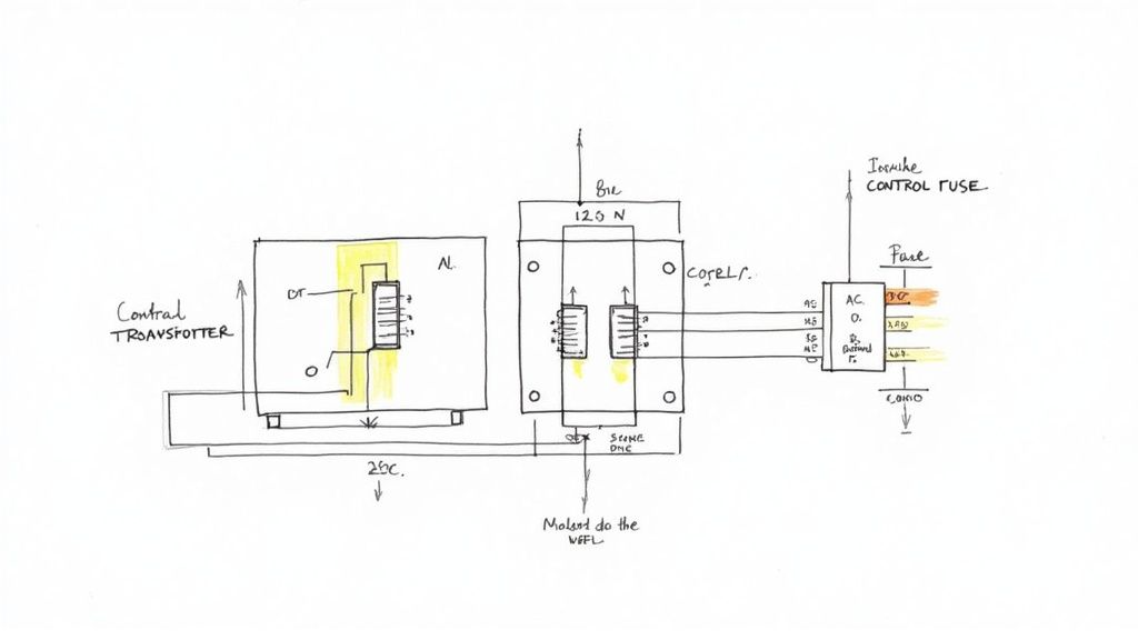
Motor Starter Shunt Trip Wiring
It’s common in packaging lines to use a 120 VAC coil on a motor starter. The shunt-trip coil ties into the starter relay via terminals T1 and T2, and a 15 A breaker usually powers the control transformer before the coil. In practice, you’ll want a 0.5 A fast-acting fuse as close as possible to the breaker terminal.
Real-world tip: run your control wires away from high-current motor leads—EMI is a silent troublemaker. If your coil runs under ten feet, AWG 16 keeps voltage drop under 5%.
Control transformer rated at 120 VAC coil voltage, minimum 100 VA
Fuse positioned within 12″ of breaker coil (per NEC 240.4)
Relay contacts sized for inrush plus 20% margin
Clearly labeled terminal blocks for T1 and T2
MCC Panel Integration
In an MCC, shunt-trip coils let you centralize shutdowns across multiple feeders. You wire each feeder’s breaker coil back to a master E-stop loop. On medium-voltage setups, you’ll sometimes see 240 VAC coils (catalogued up to 525 VAC).
The callout highlights CT+ and CT−, making the line-to-load relationship crystal clear. Label every terminal to eliminate guesswork during maintenance.
Emergency Stop Loop Integration
Safety standards often call for 24 VDC shunt coils in emergency-stop chains. You link each E-stop button in series with the coil’s normally closed contacts. A single trip breaks the loop and immediately trips the breaker.
E-stop buttons placed at all access points
Total series resistance under 2 Ω for quick detection
Dual redundant contacts to avoid a single-point failure
PLC Controlled Remote Trip
When a PLC drives your shunt coil, match the sink/output to the coil’s inrush requirements. Always add a flyback diode on DC coils to silence voltage spikes—those can mushroom into nuisance trips on long cable runs.
Verify PLC output voltage matches the coil (24 VDC or 120 VAC)
Program interlocks to kill main circuits before issuing a trip
Label terminals (e.g. C3 = COM, NO3 = normally open) in the panel legend
Transfer Switch Interlock Wiring
For generator applications, shunt-trip coils on the utility breaker prevent both sources from feeding simultaneously. Tie a 120 VAC control circuit into your ATS controller so the utility shuts off before generator power flows.
Scenario
Coil Voltage
Control Device
Notes
Utility ATS
120 VAC
ATS controller
Trips utility feed before changeover
Generator ATS
120 VAC
Changeover relay
Delays generator start until utility off
Always test interlock sequences under load to confirm correct trip timing and proper make-before-break action.
Color coding can be a lifesaver in dense enclosures. Here’s what we use on most jobs:
Red for AC trip coil conductors
Orange or yellow for DC safety loop coils
Durable printed tags on both ends of each wire
IEEE 315 or local standards for consistent wire marking
CAD Layering Best Practices
A layered CAD approach keeps your power, control and auxiliary circuits distinct. For example, isolating the shunt-trip coil on its own layer avoids clutter when you export field wiring sheets. Name layers intuitively—POWER_CTRL, COIL_CIRCUITS, TERMINALS—and assign unique colors (blue for power, green for control).
Lock background layers to prevent accidental edits
Export PDF views with layers on/off for installers
Use clear layer names that mirror your wiring documentation
With these schematics and practices, you’ll cut commissioning time and reduce miswires. Keep thermal factors, bend radii and cabinet space in mind as you adapt each example to your next project.
Commissioning And Testing Procedures
At this point, your shunt-trip wiring matches the wiring diagram for a shunt trip breaker and it’s time to fire up the panel. I always start with a hands-on visual walkthrough to catch any loose connections or misaligned labels.
Before touching live power, verify each control fuse and terminal callout against the panel drawing. It may feel like overkill, but this simple pre-check keeps you out of trouble down the line.
Here’s a quick verification checklist to run through with your team before energizing the panel:
Breaker Terminal Torque: Cross-check specs in the OEM manual
Insulation Resistance: Test all control cables at 500 VDC
Continuity Checks: Confirm every shunt-trip conductor
Secondary Voltage: Measure on control transformer before coil energization
Coil Voltage & Polarity: Record at each breakout point
Preparing Control Circuit Checks
Moving deeper into commissioning, tightening control-lug connections to 25 lb-in keeps contacts rock-steady. Personally, I’ve seen a 12% torque slip cause false trips during startup.
Next, insulation testing at 500 VDC catches hidden faults before you ever apply live voltage. In one plant, this step revealed a nicked jacket that would have led to a costly shutdown.
Isolate the control circuit and de-energize all related power sources
Set the megohmmeter to 500 V and clamp across each conductor pair
Ensure at least 50 MΩ insulation resistance on every run
Energizing And Measuring Coil Voltage
With control checks complete, energize the control transformer slowly and methodically. Remember to confirm that the fuse size and type match the coil’s inrush requirements—nothing kills momentum like a blown fuse on first power-up.
Use a calibrated meter to capture coil voltage under two scenarios:
No-Load: Read at transformer secondary terminals
Full-Load: Measure directly at coil lugs
Compare these readings to the nameplate values, aiming for within ±5% tolerance. That consistency is your ticket to reliable coil pickup every time.
Interpreting Infographic Data
The graphic lays out three common wiring flows—motor-starter integration, emergency-stop loops and PLC-driven trips. Follow each color-coded path to see exactly how the control signal returns to the breaker coil.
Simulated Trip Tests
Now it’s time to make the breaker dance on command. Hit the manual pushbutton or trigger a trip via your PLC HMI and watch the mechanism snap open.
Running remote trips through SCADA or PLC outputs means fewer techs inside live cabinets. From my experience, this approach exposed a swapped terminal before it ever hit the line.
“A simulated trip once uncovered a missing fuse link that saved us hours of downtime.”
Field Lessons And Tips
Adding a spare coil fuse in a packaging plant stopped all nuisance trips
Swapping identical coils between breakers pinpoints wiring faults fast
Log every test result with operator initials and timestamps for full traceability
Documentation For UL And NEC
UL and NEC inspections hinge on solid records. Capture torque readings, insulation values, voltage tests and simulated-trip outcomes in your commissioning report.
Key Documentation Elements
Test criteria and acceptance thresholds
Photos or screenshots of meter readings
Signed test forms alongside updated schematics
Final Acceptance And Handover
Once tests pass, circle back to your wiring diagrams and log any final tweaks. That last sign-off proves you’ve met safety and performance benchmarks.
Assemble a handover packet for operations that includes:
Revised wiring diagram for a shunt trip breaker
Commissioning checklist with pass/fail entries
Signed UL and NEC compliance certificates
Tester and inspector initials on every document
When you wrap it up this way, the panel handoff isn’t just another formality—it’s a confidence-boosting milestone for everyone involved.
Troubleshooting And Safety Tips
When a shunt-trip breaker refuses to pull in, I zero in on the coil terminals first. Sliding a clamp meter over the leads quickly confirms whether you’re missing pickup voltage or chasing a phantom issue.
Sometimes the coil fires sporadically—usually the culprit is a loose lug or compromised insulation. A quick resistance check with your multimeter, compared to OEM specs, will separate a worn-out coil from a simple wiring hiccup.
False trips aren’t just annoying; they can mask serious wiring faults. I always isolate the control circuits to reveal voltage spikes or ground faults that sneak by standard checks.
Use a calibrated digital multimeter for precise coil resistance
Deploy a clamp meter to record inrush current during a simulated trip
Inspect harnesses for chafed insulation or loose ferrules
Confirm the shunt-trip coil sees proper voltage under load
Reading Coil Resistance
Begin by locking out the main power and tagging out all control transformers. Once the coil leads are free, measure resistance across T1 and T2. A healthy 120 VAC coil typically reads between 50 Ω and 150 Ω; anything beyond a ±10% variation demands closer attention.
Always confirm control-power isolation before probing terminals to avoid shock hazards and misleading readings.
Next, trace each conductor back to its origin. I label both ends of every coil wire to prevent swapped connections. Then I verify continuity to the PLC or relay output—loose terminations often only reveal themselves under load.
Lock out main power at the breaker or disconnect switch
Tag out the control transformer and test for zero voltage
Ground test probes on the panel chassis before touching live circuits
Addressing NEC Violations
Undersized control wiring is a common NEC 110.14 violation that leads to overheating. Per Table 310.16, never go smaller than AWG 18 on AC coils.
Coil Voltage
Minimum Wire Gauge
24 VDC
AWG 22
120 VAC
AWG 18
Sticking precisely to your shunt-trip wiring diagram not only keeps you code-compliant but also boosts reliability. For an in-depth look at why breakers trip unexpectedly, check out our guide on what can cause a breaker to trip.
Voltage spikes often trigger nuisance trips. I recommend installing an RC snubber or flyback diode to tame those peaks once and for all.
Implement event logging on your PLC to capture trip signals and fault timestamps—your future self will thank you.
Final Testing And Documentation
I wrap up every commissioning session by documenting each test result right on my checklist. Capture insulation values, torque readings, and coil voltage under both no-load and full-load conditions.
Photograph meter readings at key terminals
Highlight any deviations from OEM specs and record corrective actions
Store digital copies of test forms and updated schematics in your CMMS
Keeping these records alongside updated wiring diagrams streamlines maintenance and turns audits into a quick formality.
Frequently Asked Questions
How Do I Choose The Correct Coil Voltage
In most control panels, matching your coil voltage to the control supply is the simplest way to avoid nuisance trips. I’ve seen projects stall because someone spec’d a 120 VAC coil when the PLC only offered 24 VDC.
Here’s a quick rundown of common voltages:
12 VDC – favored by many PLC outputs
24 VDC – ideal for logic-driven shunt trips
120 VAC – standard on motor-starter transformers
240 VAC – typically reserved for E-stop circuits
Always double-check the OEM datasheet or your vendor’s wiring diagram before ordering parts. A few extra minutes of review saves hours in the field.
Coil-voltage mismatches cause more nuisance trips than you’d expect. Match first, troubleshoot later.
Which Protection Devices Are Required
Coils draw a hefty inrush current the instant they energize, and that surge can trash your control circuit if you’re unprotected. I never skip a dedicated fuse or mini-breaker sized for that inrush.
Beyond the primary fuse, I recommend:
Fuse installed within 12 inches of the coil (NEC 240.4)
Flyback diode on every DC coil to clamp voltage spikes
RC snubber on AC coils when cabinet space allows
I’ve blown PCBs by ignoring transient spikes—adding a flyback diode is a tiny habit that pays huge dividends.
How Can I Integrate A PLC Trip Signal
Wiring a PLC-driven shunt-trip breaker means matching the PLC’s sink or source style to your coil voltage—and then labeling everything clearly. On a Square D QO, for example, you’d use COM and NO contacts (C3/NO3) and drop a flyback diode across the 24 VDC coil.
Key points:
Confirm the PLC output handles your coil’s inrush
Label COM and NO terminals right at the breaker
Install the flyback diode directly on the coil for best noise suppression
On one plant startup, clear labels and proper diodes saved me a full day of debugging cross-wiring issues.
How Do I Apply UL/NEC Standards
When sketching schematics, UL 489 and NEC 240.4 guide every detail. They cover breaker accessories, fuse placement, conductor ampacity and more.
Don’t overlook:
Conductor sizing and labeling per NEC table 310.16
Torque specs on lugs and terminals
Revision dates and clear schematic notes
Walk your panel regularly—check coil resistance, verify terminal torque, read labels. Those quick inspections keep unplanned downtime at bay.
Ready to optimize your next panel build? Partner with E & I Sales for premium UL-listed panels, expert wiring support, and reliable service.
When you're trying to pick the right starter for a motor, a NEMA motor starter sizing chart is your best friend. It gives you a direct, standardized way to match a starter to your motor's horsepower (HP) and voltage. No guesswork, no crossed fingers—just a clear path to selecting the right equipment.
For example, if you have a 10 HP motor running at 460V, the chart will point you directly to a NEMA Size 1 starter. This kind of straightforward guidance is what makes the NEMA system so reliable for ensuring safe and dependable operation.
Why a NEMA Sizing Chart Is Essential
Choosing the right motor starter isn't a minor detail; it's a critical decision that impacts equipment longevity, uptime, and even facility safety. A starter that's too small is a recipe for disaster, leading to premature failure, frustrating downtime, and serious electrical hazards.
A NEMA sizing chart cuts through the complexity. It gives engineers, technicians, and system designers a trusted reference built on decades of industry experience. Think of it as the foundation for maintaining the integrity and performance of your entire system. The goal is simple: make sure the starter can handle not just the motor's continuous running current, but also the massive inrush current it draws on startup. NEMA standards are famously robust, with built-in safety margins designed for the tough conditions common in North American industrial plants.
NEMA Starter Size vs Motor HP and Voltage (Three-Phase)
This table is your go-to reference for quickly finding the correct NEMA starter size. Just find your motor's horsepower and operating voltage to identify the corresponding NEMA size you'll need.
NEMA Size
Continuous Amp Rating
Max HP at 200V
Max HP at 230V
Max HP at 460V / 575V
00
9A
1.5 HP
1.5 HP
2 HP
0
18A
3 HP
3 HP
5 HP
1
27A
7.5 HP
7.5 HP
10 HP
2
45A
10 HP
15 HP
25 HP
3
90A
25 HP
30 HP
50 HP
4
135A
40 HP
50 HP
100 HP
5
270A
75 HP
100 HP
200 HP
6
540A
150 HP
200 HP
400 HP
7
810A
–
300 HP
600 HP
8
1215A
–
450 HP
900 HP
9
2250A
–
800 HP
1600 HP
As you can see, the NEMA system covers an incredible range, from fractional horsepower motors all the way up to massive industrial drivers. This standardized approach simplifies everything from design to maintenance.
Key Benefits of Using a Standard Chart
Sticking to the NEMA charts when selecting a starter brings some serious advantages that go well beyond just getting the right part number.
Enhanced Safety: This is the big one. Proper sizing prevents overloading, a primary culprit behind motor burnout and electrical fires.
Improved Reliability: It guarantees the starter's contacts and coils are beefy enough for the job, which translates directly to a longer service life and less unexpected downtime.
Streamlined Specification: Using a universal standard makes the design and procurement process much simpler, ensuring consistency across different projects and facilities.
Code Compliance: Following NEMA guidelines helps ensure your installations are up to snuff with the National Electrical Code (NEC) and other local regulations.
At the end of the day, these charts are all about matching horsepower and voltage to a specific starter size. Take a 50 HP motor at 460 volts—that lines up perfectly with a NEMA Size 3, which is rated for 90 amps of continuous current. This classification system runs from Size 00 for tiny 2 HP motors all the way up to Size 9 for enormous 900 HP units.
It's true that NEMA starters are often physically larger than their IEC counterparts, sometimes nearly double the size. But that extra bulk comes with a huge upside: durability. They are built like tanks and often rated for millions of operations, making them a fixture in demanding environments. You can learn more about how to properly size a motor starter for maximum efficiency and safety.
This chart shows some of the most common applications for NEMA starter sizes you'll encounter in the field.
It’s a great visual reminder of how each NEMA size is engineered to handle a specific horsepower range, making your selection process predictable and reliable.
Understanding Core NEMA Starter Principles
Before you even glance at a NEMA motor starter sizing chart, it pays to understand the philosophy behind their design. The National Electrical Manufacturers Association (NEMA) sets the standards for most electrical gear made and used in North America, and their whole approach is built around safety, reliability, and interoperability. NEMA standards are all about durability and generous safety factors, which is why their starters are famous for being absolute tanks built to survive harsh industrial environments.
This is a completely different world from the International Electrotechnical Commission (IEC) standards you see more often globally. IEC starters are generally smaller and more tailored to a specific job, meaning you have to nail the selection based on the exact duty cycle and load. NEMA’s way of thinking is to build a heavy-duty, field-serviceable starter that can take a beating from voltage swings and massive inrush currents without breaking a sweat.
Decoding Key Motor Nameplate Data
To pick the right starter, you first have to know how to read the motor’s nameplate. These ratings are what drive your starter sizing and, just as importantly, your overload protection settings.
Full Load Amps (FLA): This is the current your motor pulls when it's running at its rated horsepower. It’s the number one value you'll use for choosing the starter’s overload relay heater elements, which are there to protect the motor from cooking itself.
Service Factor (SF): Think of the Service Factor as a built-in "overload" capacity. It’s a multiplier that tells you how much extra load a motor can handle for short bursts without being damaged. For example, a motor with a 1.15 SF can safely operate at 115% of its rated horsepower. This is a crucial piece of the puzzle for calculating the max current for your overload relay.
Locked Rotor Amps (LRA): Also called inrush current, LRA is that massive surge of current a motor draws in the instant it starts up. We’re talking a huge spike, often 6 to 8 times the normal FLA. NEMA starters are specifically designed to handle this initial punch.
NEMA vs. IEC: A Practical Comparison
The choice between NEMA and IEC really boils down to the job at hand and where in the world you are. For the kind of heavy-duty work common in North American plants, NEMA starters are the default choice. Their rugged build and ease of service are what keep facilities running.
A huge real-world advantage of NEMA is its standardized sizing. You can often swap heater elements between different brands. This makes maintenance a lot simpler and means you don't have to stock a mountain of brand-specific spare parts—a massive plus for any large industrial site.
On the flip side, IEC starters get the nod for their compact size and lower initial cost, making them a good fit for OEM equipment or lighter-duty applications. But, they demand much more precise engineering for every single use case. For most industrial jobs in North America, the sheer durability and reliability of the NEMA system deliver better long-term value and, frankly, more peace of mind.
How to Select Overload Relays and Heater Elements
Picking the right NEMA starter size from a chart is a solid first step, but it's the overload relay and its heater elements that are the real heroes of motor protection. While the starter's contactor is busy handling the on/off switching, the overload relay acts as the motor’s dedicated bodyguard, standing watch against the damaging heat of overcurrent conditions.
So how does it work? An overload relay constantly monitors the current being pulled by the motor. If that current creeps above a safe level for too long, a heater element inside the relay gets hot and trips a mechanism. This action opens the starter's control circuit, shutting down the motor long before its windings can overheat and burn out. It's a simple, rugged, and essential process for preventing costly failures.
Calculating Maximum Allowable Amperage
Before you can pick the right heater, you need to know the motor's absolute maximum current limit. This isn't just the Full Load Amps (FLA) you see on the nameplate; you also have to factor in the motor’s built-in safety margin, known as the Service Factor (SF).
The formula is refreshingly simple:
Maximum Allowable Amps = Motor FLA x Service Factor (SF)
Let's say you have a motor with an FLA of 25 amps and a Service Factor of 1.15. The maximum current it can safely handle continuously is 28.75 amps (25 x 1.15). That number is your target. For motors with a 1.0 SF, your max amps are simply equal to the FLA. For a deeper dive, our comprehensive guide offers more on the fundamentals of the protection of motors.
Pro Tip: Always, always use the actual motor nameplate FLA for this calculation. Don't grab a generic value from a chart. Different motor designs can have slight variations in current draw, and getting this number right is the key to avoiding nuisance trips or, even worse, failing to protect your motor when it counts.
Using Manufacturer Tables to Find the Right Heater
With your maximum allowable amperage calculated, it's time to turn to the manufacturer's heater selection table. You'll find this in the documentation that comes with the motor starter. These tables are unique to each brand and model of overload relay—you absolutely cannot mix and match parts from different manufacturers.
Using the table is easy. Just find the amperage range that your calculated value falls into. The table will point you directly to the exact part number for the heater element you need. This careful matching ensures the overload relay will trip at precisely the right time, protecting your expensive motor without causing unnecessary shutdowns from harmless, temporary current spikes.
This precise sizing process is a cornerstone of the global motor starter market, which was valued at USD 7.4 billion in 2024 and continues to expand. In fact, proper sizing using a NEMA motor starter sizing chart and correct overload selection helps prevent up to 20% of industrial fires that are sparked by motor overloads. You can discover more insights about the motor starter market growth on Research Nester.
Sizing Adjustments for Special Operating Conditions
The standard NEMA motor starter sizing charts you see are based on pretty ideal conditions—think of a clean, climate-controlled facility operating at sea level. Specifically, they assume an ambient temperature no higher than 40°C (104°F) and an altitude below 3,300 feet (1,000 meters).
But let's be real, the world of industrial machinery is often much tougher than that. When your equipment operates in hotter, higher, or more demanding environments, you have to account for it in your selection. If you don't, you're just asking for nuisance trips and premature failures.
Derating for High Ambient Temperatures
Heat is the enemy of electrical components. When a starter is stuck in a hot environment, it can't dissipate its own operational heat effectively. This buildup can fool the overload relay into tripping or, worse, cook the starter's internal components.
The rule of thumb is to derate the starter's current-carrying capacity by about 8-10% for every 10°C you go above that standard 40°C mark. This almost always means you'll need to jump up a NEMA size.
Real-World Example: Imagine a motor needs a NEMA Size 1 starter, which is rated for 27A. But, it's operating in a scorching 50°C boiler room. That extra heat drops its effective capacity down to around 24A, which isn't enough. The right move is to step up to a NEMA Size 2 and then pick the correct heater element based on the motor's actual FLA.
Factoring in High Altitude Operation
Working at high altitudes introduces a similar problem, but for a different reason. The air is thinner, which means it’s much less effective at carrying heat away from the motor and the starter through convection.
Again, you'll need to derate. While it's always best to check the manufacturer's specific data sheets, a solid guideline is to go up one NEMA size for every 2,000-foot increase in elevation above the 3,300-foot baseline.
Don't forget that high altitude can also worsen voltage drop, especially over long cable runs. This adds even more stress to your system. Knowing your voltage drop calculation formulas is critical to ensure the entire system is specified correctly for the environment.
Adjusting for Severe Duty Cycles
Some applications are just brutal on starters. We're talking about frequent starting and stopping, jogging, or "plugging"—where you reverse a motor's direction before it has fully stopped. Each of these actions generates a massive amount of heat from the repeated inrush current.
For these kinds of severe-duty applications, the standard charts go right out the window. It’s common practice to select a starter that is at least one, and sometimes two, sizes larger than what the nameplate horsepower calls for. This gives you the extra thermal mass and more robust contacts needed to survive the abuse without welding themselves shut.
Selecting the Right NEMA Enclosure for Your Environment
Sizing a motor starter is only half the battle; protecting it is just as important. The enclosure is your starter's only line of defense against its operating environment, shielding it from everything from dust and moisture to corrosive chemicals and accidental contact. Skimp on the enclosure, and you’re setting yourself up for premature failure, electrical hazards, and expensive downtime.
The NEMA enclosure rating system is a standardized way to define the level of protection an enclosure provides. This system makes it straightforward to match an enclosure to the specific hazards in your facility, whether that's a clean, dry storeroom or a high-pressure washdown area in a food processing plant.
Matching NEMA Ratings to Common Industrial Settings
Different environments obviously call for different levels of protection. A NEMA 1 enclosure, for instance, is perfect for general-purpose indoor use where the main goal is simply to keep fingers away from live parts. It handles a bit of falling dirt but offers zero protection against liquids.
On the other hand, outdoor installations or indoor areas that get wet need something much more robust. A NEMA 3R enclosure is a common choice for outdoor equipment because it's built to keep out rain, sleet, and snow. For the toughest jobs involving corrosive agents or frequent hose-downs, you'll need a NEMA 4X enclosure, usually made from stainless steel or fiberglass. If you want a full rundown, you can explore the various types of electrical boxes available.
The market for enclosed motor starters tells the story of how critical this is. Valued at USD 1.87 billion in 2024, it's expected to hit USD 2.62 billion by 2032, largely because North American industries rely on them to protect their equipment. In fact, real-world data shows that using the correct NEMA-rated enclosure can slash failure rates by up to 40% in dirty or wet conditions compared to using an open-type starter. You can read more about the growth in the enclosed motor starter market at Data Bridge Market Research.
Common NEMA Enclosure Types and Applications
This quick-reference table breaks down the most common NEMA enclosure types to help you make the right call on the spot. Use this chart alongside your NEMA motor starter sizing chart to ensure you've covered both the electrical specs and the physical protection for a solid, reliable installation.
NEMA Rating
Protection Against
Typical Application
NEMA 1
Falling dirt, accidental contact
Clean, dry indoor environments like control rooms or warehouses.
NEMA 3R
Rain, sleet, snow, external ice formation
Outdoor electrical panels, irrigation pumps, and lighting controls.
Indoor manufacturing plants, machining areas, and assembly lines.
Remember, the "X" in a NEMA 4X rating is what signifies its corrosion resistance. This is a non-negotiable feature in places with chemical fumes, high humidity, or salt spray, as it stops the rust and degradation that would otherwise compromise the enclosure over time.
Common Sizing Mistakes and How to Avoid Them
Even with a solid NEMA motor starter sizing chart in hand, simple mistakes can cause a world of hurt—think nuisance tripping, fried equipment, and expensive downtime. Knowing what to watch for is the first step to getting the installation right the first time. Trust me, a few extra minutes during selection will save you hours of headaches later on.
One of the most common slip-ups I see is ignoring the motor's Service Factor (SF). A technician will grab the Full Load Amps (FLA) off the nameplate and size the overload heater based on that number alone. They completely forget that an SF of 1.15 means the motor is built to safely handle 15% more current. This oversight almost always leads to picking a heater that’s too small, causing the starter to trip when the motor is just doing its job.
Overlooking Environmental Factors
Another critical error is failing to consider the environment where the starter will live. Those standard sizing charts all assume a nice, comfortable ambient temperature—usually no more than 40°C (104°F). But what happens when you mount that starter in a blistering hot boiler room or inside an enclosure baking in the sun?
Its ability to get rid of heat plummets. This excess heat fools the overload relay into tripping, even when the motor's current is perfectly fine. The fix is to derate the starter by going up one NEMA size. This gives it the extra thermal capacity it needs to run reliably without false trips.
Troubleshooting Common Symptoms of Improper Sizing
If you know what to look for, the symptoms of an incorrectly sized starter are pretty easy to spot. These issues are almost always preventable by carefully using a NEMA motor starter sizing chart and thinking through all the variables of the application.
Here are a few tell-tale signs I’ve seen out in the field:
Nuisance Tripping: The overload just keeps kicking out for no apparent reason. More often than not, it's because the heater element is too small—either the Service Factor was ignored or no one accounted for high ambient temperatures.
Contactor Chattering: That loud, angry buzzing from the starter could be low control voltage, but it's also a classic sign that the contactor is undersized for the motor's inrush current. The contacts are literally bouncing because they can't handle the load.
Welded Contacts: This is a bad one. If the starter's contacts are fused together, you know they were nowhere near big enough for the motor's locked-rotor current. That massive inrush on startup basically arc-welded them shut, creating a massive safety hazard.
Here's the bottom line: the contactor is sized to handle the horsepower, but the overload relay is there to protect the motor. Both have to be right. If you upsize a starter for a tough application but forget to match the heater to the motor's specific FLA, you've completely defeated the purpose of the protection.
Frequently Asked Questions About NEMA Starter Sizing
Diving into a NEMA motor starter sizing chart is a great starting point, but the real-world questions often pop up once you're in the field. Getting a handle on the nuances behind these standards is what separates a good installation from a great one—ensuring everything is safe, reliable, and built to last.
Let's tackle some of the most common questions that engineers and technicians run into. Getting these details right builds confidence and helps you sidestep those frustrating pitfalls that can lead to equipment damage or unexpected downtime.
Can I Use a Larger NEMA Starter Than the Chart Recommends?
Absolutely. In fact, it's often a very smart move.
Grabbing a NEMA starter that's one size larger than what the chart calls for is a common and highly recommended practice, especially for tough, severe-duty applications. This strategy, known as "upsizing," gives you a beefy safety margin.
That extra capacity means less wear and tear on the starter's contacts and internal parts, which translates directly to a longer service life. Yes, the initial cost is a bit higher, but it's a small price to pay to prevent premature failures and the massive expense of unscheduled downtime.
There's one critical detail you can't overlook, though: the overload protection must still be sized with precision.
Crucial Point: Even if you upsize the starter's NEMA frame, the overload relay and its heater elements must be selected based on the motor's actual nameplate Full Load Amps (FLA) and Service Factor (SF). This is non-negotiable. It ensures the motor gets the right thermal protection, no matter how big the contactor is.
What Is the Main Difference Between NEMA and IEC Starters?
They both do the same basic job, but NEMA and IEC starters come from completely different design philosophies. Knowing the difference is key to picking the right component for your machinery and where it's headed.
NEMA starters, the standard across North America, are engineered to be absolute workhorses. Think robustness and durability. They are physically bigger, more heavy-duty, and have a modular design that's easy to work with. A huge plus is that parts like overload heaters are often interchangeable between different NEMA-rated brands, which really simplifies maintenance and keeping spares on the shelf.
On the other hand, IEC (International Electrotechnical Commission) starters are the go-to choice in most other parts of the world. They're designed to be compact and application-specific. While they're generally less expensive upfront, they demand a much more precise selection process based on the motor’s exact duty cycle and utilization category (like AC-3 for standard squirrel-cage motors).
NEMA Approach: A rugged, "one-size-fits-most" philosophy built for durability and with a high tolerance for punishing conditions.
IEC Approach: A tailored, space-saving, and cost-effective design that needs to be perfectly matched to the specific load.
In short, NEMA gives you a heavy-duty solution built for easy serviceability, while IEC offers a more precise, compact alternative.
How Does a Motor's NEMA Code Letter Affect Starter Sizing?
This is a fantastic question and a common point of confusion. The NEMA Code Letter on a motor's nameplate does not directly impact which NEMA starter size you choose. The starter's contactor is sized purely on the motor's horsepower and voltage, using a standard NEMA motor starter sizing chart.
So, what's the code letter for? It’s all about the upstream short-circuit protective device (SCPD)—the circuit breaker or fuse that sits ahead of the starter.
The NEMA Code Letter tells you the motor's locked-rotor kVA per horsepower, which is a direct indicator of how much inrush current it will pull on startup. A motor with a high code letter, like Code J, will draw a much bigger gulp of current than one with a lower letter, like Code B. Your breaker or fuse must be sized according to NEC Table 430.52 to handle that brief, intense spike without tripping, while still protecting the circuit from a dead short.
The takeaway? The code letter is vital for coordinating your circuit protection, not for picking the starter's NEMA size.
For all your motor control needs, from expert advice to custom UL control packaging, E & I Sales is your trusted partner. We provide premium electric motors and engineered solutions to accelerate your projects and ensure reliability. Explore our comprehensive motor control services at eandisales.com.
Think of a harmonic filter as a cleanup crew for your electrical system. When you install a Variable Frequency Drive (VFD), you get incredible control over your motors and save a ton of energy. The catch? VFDs create a lot of electrical “noise,” also known as harmonics, which can wreak havoc on your facility's power grid. A filter steps in to clean up that mess, ensuring everything runs on clean, stable power.
Why VFDs and Harmonic Filters Go Hand-in-Hand
Let’s use an analogy. Imagine your facility’s power grid is a perfectly smooth-flowing river. A VFD, for all its benefits, is like a machine that starts chopping up that smooth flow, creating all sorts of turbulence and messy currents.
That electrical turbulence is what we call harmonic distortion. It pollutes the power quality for every piece of equipment connected to that grid. We get into the nitty-gritty of how they work in our guide on variable frequency drive basics, but the most important thing to know is that VFDs are non-linear loads.
Instead of drawing power in a smooth, continuous wave, they take it in short, sharp gulps. Those abrupt pulses are the very source of harmonic pollution.
The Real-World Impact of Harmonics
Ignoring harmonics isn't just a technical detail—it's a direct threat to your plant's reliability and your bottom line. This "dirty power" travels everywhere, causing all sorts of strange, intermittent problems that are a nightmare to diagnose.
Without a good filter, you’re likely to see issues like:
Overheating Equipment: Transformers, motors, and even wiring can start running dangerously hot, drastically shortening their service life.
Nuisance Tripping: Circuit breakers pop for no obvious reason, causing frustrating and expensive downtime.
Control System Glitches: PLCs, sensors, and even your network equipment can start acting up or failing because their power source is corrupted with noise.
Wasted System Capacity: Harmonics eat up the capacity of your electrical system, meaning you can't add new equipment without first making expensive upgrades.
A harmonic filter is essentially a water treatment plant for your electrical river. It intercepts the pollution from the VFD and restores the clean, smooth power that your other equipment needs to run properly.
A Growing Industrial Necessity
The link between VFDs and harmonics is so strong that the filter market is growing right alongside VFD adoption. Projections show the harmonic filter market climbing from USD 933.86 million in 2025 to over USD 1.18 billion by 2030.
This isn't a coincidence. As more industries rely on VFDs, they're discovering that a standard six-pulse drive can easily push distortion levels into a problematic 30–40% range if left unchecked. As companies get serious about reliability and meeting power quality standards, filters are moving from a "nice-to-have" to a must-have component. You can see more on this trend in this harmonic filters market forecast.
When it's time to choose a harmonic filter for your VFD, you’ll quickly find yourself at a fork in the road: Passive or Active. This isn't about picking the "best" one, but about finding the right tool for the job. The decision you make here will ripple through your system's performance, your budget, and even long-term reliability.
To get a grip on the difference, think of it like dealing with unwanted noise.
A passive filter is like a well-designed soundproofing panel. It’s made of specific materials—inductors, capacitors, and resistors—that are perfectly tuned to absorb a particular frequency of noise. It just sits there and does its one job really, really well.
An Active Harmonic Filter (AHF), on the other hand, is like a pair of high-end noise-canceling headphones. It actively listens to the noise, figures out its pattern, and generates an exact opposite sound wave to completely cancel it out in real time. It's a smart, dynamic solution.
The Passive Filter Approach
Passive filters are the tried-and-true workhorses of harmonic mitigation. They are built from simple components—inductors and capacitors—that are precisely tuned to a specific harmonic frequency. They create an easy path to ground, essentially trapping and diverting that specific flavor of electrical noise away from your system.
Because they are “tuned” for common troublemakers like the 5th or 7th harmonics that VFDs love to create, they are fantastic in predictable environments. If you have a steady load and know exactly what you’re dealing with, a passive filter is a robust and cost-effective solution.
Best For: Single VFDs or a bank of drives that all run at a consistent speed and load.
Example Application: Think of a big exhaust fan or a pump in an HVAC system that just runs at a steady clip all day long.
Key Advantage: They are simple, tough, and much easier on the initial budget. With fewer moving parts, there’s less that can go wrong.
But that specialization is also their biggest drawback. If your system’s frequency profile changes, or if the utility power feeding your plant is already messy, a passive filter can lose its effectiveness. In a worst-case scenario, a poorly matched passive filter can actually create resonance and make your harmonic problems even worse.
The Active Filter Advantage
Active Harmonic Filters are a whole different ballgame. They use sophisticated power electronics—fast-switching transistors (IGBTs) and a smart controller—to constantly watch the electrical system.
A current transformer (CT) acts as the filter's "ears," measuring the distorted current waveform coming from the VFD. The AHF’s controller instantly analyzes this dirty signal and injects a perfectly opposing current to cancel out the harmonic distortion. This happens thousands of times a second, allowing the filter to adapt on the fly to whatever the VFDs are doing.
An active filter doesn't just block noise; it actively erases it. By injecting a mirror-image counter-current, it forces the waveform drawn from the power grid back into a clean, smooth sine wave.
This incredible adaptability makes active filters the clear winner for complex facilities. If you’ve got multiple VFDs, loads that are all over the place, or you’re under the gun to meet tough power quality standards, an AHF is often the only way to get there. They can tackle a whole range of harmonics at once and even help out with power factor correction as a bonus.
Passive vs Active Harmonic Filters At a Glance
Choosing between these two technologies really boils down to balancing your immediate needs and your budget. Here’s a quick rundown of how they stack up.
Characteristic
Passive Filter
Active Filter
Mitigation Method
Diverts specific, targeted frequencies
Injects an opposing current to cancel distortion
Performance
Good for specific, predictable harmonics
Excellent, broad-spectrum correction
Adaptability
Fixed; performance can drop with system changes
Highly dynamic; adapts instantly to changing loads
Initial Cost
Lower
Higher (often 2-3x the cost of a passive unit)
Size
Can be quite large, especially for high amps
Generally more compact
Ideal Load
Stable, consistent loads
Dynamic, variable, and multiple non-linear loads
Complexity
Simple and rugged
Complex power electronics require skilled integration
For a facility with a lot of non-linear loads all feeding into a common bus, or for anyone who absolutely has to meet strict IEEE 519 standards, an active filter is almost always the answer. The upfront investment is higher, no doubt. But in complex industrial environments where uptime is everything, the superior performance and operational flexibility often deliver a far better return in the long run.
Playing by the Rules: Why IEEE 519 Matters
When we talk about standards like IEEE 519, it's easy to get lost in the numbers and think of it as just another compliance hurdle. But it’s much simpler than that. Think of it as being a good neighbor on the electrical grid. Your utility company works hard to deliver clean, stable power to your facility, and in return, they need you to avoid dumping electrical "noise" back onto the line.
That noise is what we call harmonic distortion, and it's a natural byproduct of modern equipment like VFDs. If every facility let its harmonics run wild, the combined effect could destabilize the entire grid. That’s why these standards exist—to keep the shared power source clean and reliable for everyone connected to it.
Finding the Line: The Point of Common Coupling
So, where do the utility police actually measure this "noise"? That happens at a specific spot called the Point of Common Coupling (PCC).
The PCC is simply the official handoff point where your facility’s electrical system connects to the utility's grid. Picture it like the water meter at your property line; it’s the exact spot where the utility company measures what you're sending back. It’s at this PCC where your harmonic levels have to meet the limits set by IEEE 519.
At its core, IEEE 519 is a gentleman's agreement. The utility promises to deliver clean power, and you promise not to pollute that shared power. Harmonic filters are what allow you to hold up your end of the bargain.
What the Numbers Actually Mean
IEEE 519 isn't a one-size-fits-all rule. The harmonic limits you need to hit will change based on your system's voltage and how much power you draw. The general rule of thumb? The bigger your service and the higher the voltage, the tighter the limits get.
The standard really boils down to two key things:
Total Harmonic Distortion (THD): This is the big-picture number. It’s an overall score that represents the total amount of harmonic noise you're creating.
Individual Harmonic Limits: The standard also gets specific, putting caps on the individual troublemakers—like the 5th, 7th, and 11th harmonics—that VFDs are notorious for producing.
These limits are always expressed as a percentage of your maximum load. A very common target, for instance, is keeping your Total Demand Distortion (TDD)—which is just THD measured under full load—below 5% at the PCC. To get there, you almost always need properly engineered harmonic filters for VFD applications.
Tackling harmonics does more than just keep the utility happy; it makes your own system more efficient. Cleaning up your power reduces heat and wasted energy, which can also help improve your power factor. If you want to go deeper on that, our guide on the power factor definition is a great place to start. In the end, meeting IEEE 519 standards isn't just about avoiding a penalty—it’s about running a smarter, more reliable, and more efficient operation.
How to Size and Select the Right Harmonic Filter
Choosing the right harmonic filter isn't like picking a part off a shelf. It’s much more like getting a prescription filled—it has to be the right solution for a specific problem. If you undersize it, the filter won't do its job. Oversize it, and you’re just wasting money. The sweet spot is finding a solution that cleans up your power just enough without over-engineering the fix.
This is where we move from theory into the real world. The entire process starts with one critical step: gathering the right data. Before you even glance at a product spec sheet, you need a clear, accurate picture of your electrical environment.
Start with a Power Quality Analysis
First thing's first: you need a power quality analysis. Skipping this is like a doctor prescribing medicine without running any tests—you're just guessing, and the consequences can be serious. This analysis gives you the hard data, the baseline you absolutely need to specify the right harmonic filter for your VFD.
The process involves hooking up a power quality meter at critical points in your system, especially at the Point of Common Coupling (PCC). This isn't a quick snapshot; the meter stays on for a period to capture the full ebb and flow of your facility's operational loads.
Here’s what you’re looking for:
Existing Background Distortion: What's the Total Harmonic Distortion (THD) on your system before adding the new VFD or filter? This tells you if you're starting with a clean slate or walking into an existing mess.
VFD Load Profile: How much current is the VFD actually drawing, and how much does it change? A fan running at a steady 80% speed creates a much different harmonic signature than a crane VFD with its wild, unpredictable load swings.
Specific Harmonic Orders: The analysis breaks down the distortion into its component parts—the 5th, 7th, 11th harmonics, and so on. This is crucial for picking a filter that targets the frequencies causing the most trouble.
System Impedance: You need to understand how "stiff" your electrical system is. This helps predict how the grid will react to both the VFD and the filter you're about to add, letting you sidestep dangerous resonance problems.
Decoding Filter Specifications
Once you have that data in hand, you can finally start looking at filters. The numbers on a spec sheet aren't just marketing fluff; they are performance metrics that should directly map back to the problems you just measured.
You'll see terms like correction current, which is the maximum amount of harmonic garbage the filter can actively cancel out. This number needs to be higher than the harmonic current your VFD is producing. You'll also find attenuation levels, often shown on a chart, which detail how well the filter knocks down specific harmonic orders.
Think of it this way: Your power quality analysis tells you the size and shape of your harmonic problem. The filter’s spec sheet tells you the size and shape of the solution it provides. Your job is to find the perfect match.
This decision tree gives you a great starting point for that first big question: are you compliant with standards like IEEE 519 right now?
If you land on the "Filter" branch, the real work begins. Now you have to match the right technology to your specific application.
Matching Filter Technology to Your Needs
The data from your analysis will point you toward the right type of filter. If your VFD runs a stable, predictable load, a simple and cost-effective passive filter tuned to the problem frequencies (usually the 5th and 7th) is often all you need.
But for more complex systems—think multiple VFDs or loads that are all over the place—an active harmonic filter (AHF) is almost always the better bet. We're seeing much faster adoption of active filters in the field because their performance is so immediate and measurable compared to older passive designs. Industry reports show the AHF market is growing quickly as facility managers realize the value of real-time, dynamic correction for fluctuating VFD loads.
A properly sized active filter can take your THD from an unfiltered mess down to single-digit territory, often <5–8%, which is what you need to meet strict utility limits. You can see more on this trend in this harmonic filter market analysis. By putting in the work to gather data upfront, you guarantee the filter you choose is a precise, effective, and financially sound investment.
Installation Best Practices for Peak Performance
You’ve done the hard work and selected the perfect harmonic filter for your VFD. That's a huge step, but the job is only half done. A top-of-the-line filter installed the wrong way is like buying a high-performance engine but forgetting to hook up the fuel line—all potential, no results.
Proper installation is what turns your investment into real-world performance. Getting it right from the start means you avoid common headaches like poor filter effectiveness, nagging safety hazards, and even interference with the very equipment you’re trying to protect.
Let's walk through the best practices that ensure your harmonic filter for VFD systems deliver from day one.
Location, Location, Location
Just like in real estate, placement is everything. The physical spot you choose for the filter in relation to the VFD has a massive impact on its effectiveness. Botch the location, and you’re setting yourself up for compromised performance and future maintenance nightmares.
Here’s what really matters for physical placement:
Get Close to the VFD: Your filter needs to be installed as close to the VFD as physically possible. Shorter conductor runs between the two mean less voltage drop and less radiated noise (EMI). Long cables can act like antennas, broadcasting the very electrical noise you’re trying to eliminate.
Give It Room to Breathe: Both VFDs and harmonic filters throw off a good bit of heat. Squeezing them into a stuffy, unventilated cabinet is a surefire way to cause overheating and premature failure. Always follow the manufacturer’s clearance requirements to ensure there's enough airflow. For bigger filters, this might even call for a dedicated ventilated cabinet.
Plan for Maintenance Access: While you want the filter snugged up next to the VFD, don't make it impossible to work on. Make sure a technician can safely get to the terminals for inspections, connections, or troubleshooting without having to kill power to half the plant.
The Critical Role of the Current Transformer
When you're dealing with an active harmonic filter (AHF), no single component is more crucial to its operation than the Current Transformer (CT).
Think of the CT as the filter's eyes and ears. It's constantly measuring the harmonic currents flowing from the VFD and feeding that data back to the filter's brain. The filter then uses this information to calculate the exact counter-current it needs to inject to cancel out the distortion.
If the CT is in the wrong place, the active filter is effectively blind. It can't see the harmonic distortion it's supposed to cancel, rendering the entire unit useless.
The CT must be installed so it measures the current of only the non-linear loads (the VFDs) it’s meant to correct. It should be placed after the filter's point of connection but before the VFDs. If you put it where it can also measure the filter’s own corrective current, you’ll create a confusing feedback loop that sends the system into a tailspin.
Wiring and Grounding Done Right
Sloppy wiring and poor grounding are probably the two most common culprits behind post-installation problems. These aren't just minor details—they're the foundation for a safe and effective system.
Use the Right Size Wire: Don't guess. Always use conductors sized for the filter's full load amperage, following all local electrical codes. Undersized wires can overheat, creating a serious fire hazard while also causing a voltage drop that cripples the filter's performance.
Keep Power and Control Separate: Make it a rule to route your low-voltage control wires in a separate path from the high-power cables. Running them together in the same conduit is an open invitation for noise to bleed into the control circuits, which can cause erratic and unpredictable filter behavior.
A Solid Ground is Non-Negotiable: A clean, low-impedance ground path is absolutely essential. It’s not just for safety; it’s what gives all that electrical noise a path away from your sensitive equipment. Use the dedicated grounding lug on the filter and connect it directly to the main system ground. No shortcuts.
Calculating the ROI of Harmonic Filtering
So, how do you justify the cost of a harmonic filter to the people signing the checks? It’s one thing to talk about meeting standards like IEEE 519, but the most convincing argument always comes down to the numbers. You have to prove that a filter isn't just another line-item expense—it's a smart investment that pays for itself.
Calculating the Return on Investment (ROI) is how you shift the conversation from a technical problem to a financial solution. A well-chosen filter doesn't just cost money; it makes and saves money over time, often in ways that are easy to miss. By putting real dollars to the benefits, you can show that doing nothing is actually the most expensive option.
Quantifying the Tangible Savings
The payoff from clean power goes way beyond just ducking utility fines. The real money is found in making your whole operation more efficient and reliable. These aren't just fuzzy concepts; they show up as real dollars on your balance sheet.
When building your case, you’ll want to hit these three financial pillars hard:
Reduced Energy Waste: Think of harmonic currents as electrical "junk food." They do nothing but create extra heat in your transformers, cables, and motor windings without contributing any real work. This wasted power, known as I²R losses, pads your utility bill every month. A filter cuts out this junk, which means you stop paying for energy that's just turning into heat. We dive deeper into this in our guide on VFD energy savings.
Extended Equipment Lifespan: That excess heat isn't just wasting energy; it’s actively cooking your equipment from the inside out. Transformers and motors running hot because of harmonics are on a fast track to failure. A filter acts like a bodyguard for these critical, expensive assets, helping them last longer and pushing huge replacement costs further down the road.
Minimized Costly Downtime: Nothing kills profits like an unplanned shutdown. Harmonics are a notorious cause of those frustrating "nuisance trips," where breakers pop for no clear reason, or sensitive PLCs and controls get scrambled, bringing a production line to a dead stop. By cleaning up the power, a filter stops these disruptive and incredibly expensive interruptions before they happen.
A Real-World ROI Scenario
Let's put some numbers to it. Picture a mid-sized manufacturing plant with a bunch of VFDs on its main production lines. Before installing filters, they were burning through about one oversized motor a year from overheating, costing them $15,000 a pop. On top of that, nuisance trips were causing about four hours of unplanned downtime a year, and every hour the line was down cost them $10,000 in lost production.
Here’s how the math breaks down for them:
Annual Cost of Downtime: 4 hours x $10,000/hour = $40,000
Annual Motor Replacement Cost: 1 motor x $15,000 = $15,000
Total Annual Avoidable Costs: $40,000 + $15,000 = $55,000
By investing $70,000 in a properly sized active harmonic filter, the facility could see a full payback in just over a year. After that, they’d be pocketing an extra $55,000 in savings, year after year.
This kind of breakdown changes everything. The filter is no longer just something you have to buy for compliance. It becomes a proactive move to boost reliability and efficiency. If you need to build an even more detailed business case, there are plenty of great ROI calculation resources out there that can help.
Common Questions About VFD Harmonic Filters
When you start digging into harmonic filters for VFDs, a bunch of practical questions pop up. When do I actually need one? Where does it go? Why is it so important? These things are absolutely critical for keeping your electrical system healthy, but it's easy to get bogged down in the technical details.
Let's cut through the noise. Here are some straightforward answers to the questions we hear most often, so you can make the right call and troubleshoot with confidence.
Do All VFDs Require a Harmonic Filter?
Not every single VFD needs a filter right out of the box, but in most real-world industrial and commercial shops, it’s something you have to seriously consider. The real decision comes down to a few key things: how big your drive is compared to your whole power system, how sensitive other equipment on the same circuit is, and what your local utility demands (like meeting the IEEE 519 standard).
Sure, one little VFD on a massive, bulletproof electrical system probably won’t cause enough of a ruckus to matter. But the moment you start adding multiple VFDs, or one single large drive, that harmonic noise adds up fast. In those cases, a filter stops being a "nice-to-have" and becomes essential for preventing system-wide headaches and staying compliant.
What Is Total Harmonic Distortion (THD)?
Total Harmonic Distortion, or THD, is the go-to metric for measuring the "cleanliness" of your power. Think of it like a single grade that tells you how much electrical garbage is polluting your power signal compared to a perfect, clean sine wave.
A low THD percentage means you’ve got clean, stable power. A high THD means you've got significant distortion that can beat up your equipment. Standards like IEEE 519 put hard limits on THD to keep the grid stable, often telling facilities they have to keep distortion below 5% where their power comes in.
Can a Harmonic Filter Improve Energy Efficiency?
Yes, absolutely. This is a big one that often gets overlooked. Harmonic currents are just wasted energy. They don't do any useful work—they can't help turn a motor shaft. All they do is create destructive extra heat in your transformers, wiring, and the motors themselves. That's pure wasted electricity, and you're paying for it on your utility bill.
By knocking out these useless harmonic currents, a filter cuts down on that wasted heat, what we call I²R losses. The result is a more efficient electrical system, less heat stress on your gear, and real, measurable energy savings over time.
Where Should a Harmonic Filter Be Installed?
The rule of thumb is that harmonic filters get installed on the "line side" of the system. This just means you place the filter between your main power feed and the Variable Frequency Drive.
Putting it there is strategic. It allows the filter to catch and scrub out the harmonic currents the VFD creates before they can bleed back into the rest of your facility's electrical network or escape out onto the utility grid. Getting the placement right isn't optional—it’s what makes the filter do its job and protect your whole system.
At E & I Sales, we live and breathe this stuff. We engineer rugged, reliable motor control solutions that keep your plant running without a hitch. If you're trying to sort out VFDs and harmonic mitigation, our team has the field experience to design and build a system that nails your exact requirements.
Contact us to make sure your power quality is locked in. Learn more at https://eandisales.com.
Think of a Variable Speed Drive (VSD) as the accelerator for an electric motor. Instead of being stuck at one speed—full throttle—it lets the motor run at the exact speed needed for the job at hand. This simple but powerful capability is what unlocks incredible energy savings and precise process control.
It all comes down to adjusting the electrical frequency fed to the motor.
Unlocking Smarter Motor Control
Imagine trying to drive your car with only two options: full stop or pedal to the floor. That’s essentially how countless traditional electric motors work. They’re either off or running at a constant, maximum speed. While simple, this all-or-nothing approach is wildly inefficient for most real-world jobs.
A VSD completely flips that script. Instead of relying on clumsy mechanical parts like dampers or valves to throttle down the output, the VSD acts as the motor's brain. It intelligently dials the motor's speed up or down to perfectly match the application's real-time demand, ensuring not a single watt of power is wasted.
From Wasted Energy to Precise Performance
At its core, a VSD takes the standard, fixed-frequency power from the grid and converts it into a variable-frequency power source for the motor. Since an AC motor's speed is directly linked to the frequency of its power supply, changing the frequency means you change the speed. Simple as that.
This opens the door to some serious benefits:
Massive Energy Savings: Just by running a motor only as fast as it needs to, VSDs can slash energy consumption by up to 60%, especially in common applications like pumps and fans.
Enhanced Process Control: VSDs give you pinpoint control over flow, pressure, and speed. This leads directly to higher-quality products and more consistent operations.
Reduced Mechanical Stress: The soft-start and stop capabilities of a VSD get rid of the sudden jolt that hammers equipment. This extends the life of critical components like belts, gears, and bearings.
It’s a common myth that VSDs are only for complex, high-tech systems. The truth is, their ability to match a motor’s output to the actual load makes them a smart financial move for almost anything, from a simple conveyor belt to a sophisticated HVAC system.
VSD vs. VFD: What's the Difference?
You'll often hear the terms VSD (Variable Speed Drive) and VFD (Variable Frequency Drive) thrown around like they're the same thing—and for the most part, they are.
When we're talking about AC motors, they refer to the exact same technology. VFD is just a more specific term that describes how the drive controls speed: by varying the frequency. VSD is a broader, more general term. But in today's industrial world, if someone says VSD, they almost always mean a VFD. If you want to get into the technical nitty-gritty, you can learn more about AC motor variable speed control and the principles behind it.
To put it all in perspective, here’s a quick rundown of how a VSD changes the game compared to old-school motor control.
VSD Control vs Traditional Motor Control At a Glance
Feature
Traditional Motor (Fixed Speed)
VSD Controlled Motor (Variable Speed)
Speed Control
Runs at a single, constant speed.
Speed is fully adjustable from zero to maximum.
Energy Efficiency
Often inefficient, especially at partial loads.
Highly efficient, matching energy use to demand.
Process Control
Limited; requires mechanical throttling.
Precise and immediate control over processes.
Equipment Wear
High mechanical stress during startup.
Smooth starts and stops reduce wear and tear.
As you can see, the difference is night and day. A VSD gives you the flexibility, efficiency, and control that a fixed-speed motor simply can't match.
How a Variable Speed Drive Actually Works
At its core, a variable speed drive is like a sophisticated power translator for an electric motor. It takes the standard, fixed-frequency AC power from the grid and cleverly transforms it into a new AC power source where the frequency can be adjusted on the fly. This ability to manipulate frequency is the secret to controlling a motor’s speed with surgical precision.
Think of it as a three-stage journey that turns raw, inflexible power into smart, adaptable energy. Each stage has a specific job, working in perfect sync to give you total command over your motor. The entire process is a seamless AC-to-DC-to-AC conversion that happens in the blink of an eye.
This is a big deal because, without this control, you’re stuck with a motor that only knows one speed: full blast.
As the graphic shows, running a motor at full speed when it isn't needed is the same as leaving cash on the table. A VSD fixes that.
Stage 1: The Rectifier Converts AC to DC
The journey starts at the rectifier, which is the VSD’s front door for incoming power. Its one and only job is to take the alternating current (AC) from your facility and convert it into direct current (DC). The AC power from the wall outlet naturally flows back and forth in a sine wave, which is great for long-distance transmission but terrible for precise control.
To build an adjustable output, the VSD first needs a stable, one-way power source to work with. The rectifier, usually built with high-power diodes, acts like a series of one-way valves. It lets electricity flow in but not back out, effectively ironing out the AC waves into a steady stream of DC voltage.
Stage 2: The DC Bus Stores and Smooths the Power
Once converted, this raw DC power flows into the DC bus, which acts like a power reservoir. It’s mainly made up of big capacitors that store the electrical energy, making sure a clean and stable supply is ready for the final stage.
Picture the DC bus as the calm water held in a reservoir behind a dam. The rectifier fills it up, and the capacitors ensure the water level (voltage) stays perfectly constant, filtering out any ripples or hiccups from the conversion. This smooth, stored DC power is absolutely essential for creating a clean AC waveform on the other side.
A stable DC bus is the foundation of the drive's performance. Without it, the final AC output to the motor would be choppy and erratic, leading to poor performance and even potential damage.
Stage 3: The Inverter Creates a New, Adjustable AC Signal
This is it—the final and most critical stage is the inverter. This is where the real magic of variable speed control happens. The inverter takes that smooth DC power from the bus and, using a set of incredibly fast electronic switches (typically Insulated Gate Bipolar Transistors, or IGBTs), chops it up into thousands of precisely timed pulses per second.
By controlling the timing and width of these pulses—a technique called Pulse Width Modulation (PWM)—the inverter can build a brand-new, synthetic AC sine wave from scratch. And here's the key: the frequency of this new wave is completely under your control.
To run the motor slower, the inverter creates a lower-frequency AC waveform.
To run the motor faster, it generates a higher-frequency waveform.
This newly minted, variable-frequency AC power is then fed to the motor, dictating its exact rotational speed. The motor simply follows the frequency it’s given, giving you the power to match its output perfectly to what your application actually needs. No more waste, just pure, precise control.
The Main Components and Types of VSDs
To really get what a variable speed drive is, you have to look under the hood. Think of it like a car engine—you have the block, pistons, and crankshaft all working in concert. A VSD is no different; it’s an assembly of key electronic components that have to work together perfectly to give you that precise motor control.
Each part has a specific job in the AC-to-DC-to-AC power conversion process that makes the whole thing possible.
While the big hardware handles the power, a sophisticated control unit is the maestro orchestrating the whole performance.
Unpacking the Core Hardware
A VSD isn't just one magic box. It’s a system made up of four essential parts, and knowing what each one does makes it much clearer how the drive pulls off its magic trick.
Rectifier: This is where the power from the grid first enters the drive. Its only job is to take that incoming alternating current (AC) and, using a series of diodes, turn it into direct current (DC).
DC Bus: Basically a big electrical reservoir made of capacitors. The DC bus takes the power from the rectifier, smooths it out, and stores it. This ensures the next stage gets a stable, clean supply of DC power to work with.
Inverter: This is the real heart of the VSD. It takes that smooth DC power from the bus and, using incredibly fast-switching transistors (usually IGBTs), chops it up to build a brand-new, synthetic AC waveform with whatever frequency and voltage is needed.
Control Unit: The brain of the whole operation. This microprocessor is constantly monitoring motor feedback, user commands, and system status. It tells the inverter exactly what kind of waveform to create to hit the target speed and torque.
These four pieces work in lockstep to turn a simple command—like "run this pump at 75% speed"—into a precisely engineered electrical output.
The Major Categories of VSDs
Not all drives are built the same. They come in different flavors, each designed with specific technologies for different jobs, from simply slowing down a fan to running high-precision robotics. The two main categories are defined by how they handle the power internally.
Choosing the right type of VSD is less about which one is "better" and more about matching the technology to the demands of the job. A high-performance drive is overkill for a simple pump, while a basic drive can't handle a complex servo application.
The most common distinction you'll run into is between Voltage Source Inverters and Current Source Inverters.
Voltage Source Inverters (VSI): This is the workhorse of the industry. By far the most common type of VSD you’ll find, a VSI creates a variable voltage output. This makes them incredibly versatile, cost-effective, and a perfect fit for the vast majority of industrial applications.
Current Source Inverters (CSI): You don't see these as often. CSIs are typically reserved for very high-power, medium-voltage applications—think massive industrial fans or pumps. They regulate current instead of voltage, which gives them unique advantages for controlling huge motors, but they come with a higher price tag and more complexity.
Beyond that fundamental split, VSDs are also grouped by their performance capabilities. A standard drive, often called a V/Hz or scalar drive, is perfect for simple tasks where you just need to adjust speed, like on a fan or pump, and don't need dead-on torque control.
For the more demanding jobs, you step up to vector control or servo drives. These high-performance drives use sophisticated algorithms to independently manage both the motor's speed and torque with incredible accuracy. This makes them essential for things like machine tools, complex conveyors, and robotics, where precise positioning and a dynamic response are non-negotiable.
The Business Case for Installing VSDs
While the tech behind a variable speed drive is interesting, the real question for any business is simple: why should you invest in one?
It really comes down to a powerful mix of massive energy savings, tighter process control, and better long-term equipment health. A VSD isn't just an operational upgrade; it’s a smart financial move with a clear—and often very quick—return on investment.
The biggest benefit, the one that gets everyone’s attention, is the dramatic drop in energy consumption. This is especially true for anything with pumps and fans, which follow a fascinating set of rules known as the Affinity Laws.
These laws show a powerful link between a motor's speed and its power draw. In short, the power needed is proportional to the cube of the motor's speed. This creates an exponential curve where even a tiny reduction in speed leads to a massive drop in energy use.
The Power of the Affinity Laws
Think about it like this: if you slow a fan down by just 20%, you don't save 20% on your energy bill. Thanks to the Affinity Laws, that 20% speed reduction actually slashes the fan's energy use by nearly 50%.
That’s a complete game-changer for facilities with big HVAC systems or fluid-pumping operations. A seemingly minor tweak becomes a major cost-cutting measure. You can see how this plays out in the real world in our detailed look at VFD energy savings.
This is where VSDs really shine. Instead of running a pump at full blast and using a valve to choke the flow—which is like driving with one foot on the gas and the other on the brake—a VSD just slows the motor down to deliver the exact flow you need.
By precisely matching motor speed to the load demand, a VSD eliminates the wasted energy inherent in fixed-speed systems. This isn’t just incremental improvement; for many businesses, it’s the single most impactful energy efficiency upgrade they can make.
More Than Just Energy Savings
The energy savings are fantastic, but the business case for VSDs goes way beyond a lower utility bill. The enhanced control and gentler operation they provide bring a ton of other valuable perks to the table.
Improved Process Control: For any application needing precise pressure, flow, or tension, VSDs offer incredible accuracy. They can hold a setpoint with rock-solid stability, which leads to better product quality, less wasted material, and more consistent output.
Reduced Mechanical Stress: A standard motor kicks on with a violent, instant jolt of power. That shockwave slams into belts, gears, and couplings. A VSD, on the other hand, gives you a smooth, controlled "soft start," gradually ramping up the motor's speed. This gentle acceleration drastically cuts down on mechanical wear and tear, making your equipment last longer and lowering maintenance costs.
Lower Maintenance and Repair Costs: When equipment runs smoother and only as fast as necessary, parts don't wear out as quickly. Fewer emergency repairs mean less unplanned downtime, which directly protects your bottom line.
The market is certainly taking notice. Global VFD market projections show growth from USD 24.7 billion in 2025 to USD 32.0 billion by 2030. This trend is fueled by real results; in water treatment plants, for example, VFDs can cut pumping energy by 20-60%. A single 100 kW pump with a VFD can save 200,000 kWh a year, which can mean over $20,000 back in your pocket.
For manufacturers, figuring out smart strategies to reduce manufacturing costs is always a priority, and VSDs are a huge piece of that puzzle. By combining direct energy savings with less maintenance and better process quality, a VSD is a multi-pronged attack on operational spending that directly boosts profitability.
How to Select the Right VSD for Your Application
Choosing the right variable speed drive isn't just about grabbing one off the shelf. It’s a crucial decision that hinges on a deep understanding of your motor, the job it’s doing, and the environment it lives in. Get this right, and you'll unlock those promised energy savings and gain incredible process control. Get it wrong, and you're looking at performance headaches, premature failure, and money down the drain.
The whole process kicks off with the basics: your motor’s nameplate. That little metal plate is packed with the critical data you need to size the VSD correctly.
Sizing Your Drive with Motor and Application Data
Properly sizing a VSD is hands-down the most important first step. An undersized drive will constantly trip on faults and eventually burn out, while an oversized one is just a waste of capital. The goal is to perfectly match the drive's capabilities to both the motor it's controlling and the actual work that motor has to do.
First things first, grab these key details from the motor’s nameplate:
Full Load Amps (FLA): This is the big one. Your VSD absolutely must be rated to handle the motor’s maximum current draw when it's working its hardest.
Horsepower (HP) or Kilowatts (kW): While amps are the priority, the HP rating is a great way to double-check that you’re in the right ballpark.
Voltage: Simple but critical. The drive's input voltage has to match your available power supply, whether that’s 480V, 240V, or something else.
Beyond the motor itself, you have to think about the application’s torque requirements—the amount of rotational force the motor needs to generate. You can dive deeper into the fundamentals in our guide on how to calculate motor torque.
A common mistake is sizing a drive based on horsepower alone. Always, always prioritize the motor's Full Load Amps (FLA). It’s a far more accurate measure of the electrical load the VSD will actually see.
Applications typically fall into two torque profiles, and your VSD choice needs to reflect which one you're dealing with:
Variable Torque: Think centrifugal fans and pumps. The torque needed goes up as the speed increases. Since they require very little torque at low speeds, these applications are the superstars for massive energy savings.
Constant Torque: This is your world of conveyors, mixers, and extruders. They demand the same amount of muscle from the motor whether it’s crawling or running at full tilt. These loads need a robust VSD that can deliver consistent, high torque even at very low RPMs.
Tackling Power Quality and Harmonic Distortion
One of the biggest hurdles when integrating a VSD is harmonic distortion. In plain English, the super-fast electronic switching happening inside the drive creates electrical "noise" that can pollute your facility's power grid. This distortion can wreak havoc on other sensitive electronic equipment sharing the same circuit, causing bizarre malfunctions or even permanent damage.
Luckily, this is a well-known issue with proven fixes. The most common way to fight back is by installing a line reactor or a specialized harmonic filter. A line reactor is basically an inductor coil that you place on the input side of the VSD. It acts like an electrical shock absorber, smoothing out the current and filtering out a huge chunk of those damaging harmonics. For more severe cases, you might step up to a dedicated active or passive harmonic filter to guarantee clean power.
Considering Environmental and Compliance Factors
Finally, a VSD has to be tough enough to survive in its home. The drive's enclosure is rated to protect its delicate electronics from things like dust, moisture, and chemical spray. These ratings are standardized by NEMA (National Electrical Manufacturers Association).
NEMA 1: Your standard choice for clean, dry, indoor spots.
NEMA 12: Offers protection from circulating dust and light, non-corrosive drips.
NEMA 4X: The workhorse for harsh, wet, or wash-down areas, built to resist corrosion.
Meeting safety standards from organizations like UL (Underwriters Laboratories) is also completely non-negotiable. A properly rated and certified drive is essential for meeting regulations and protecting both people and equipment. This kind of foresight is becoming even more critical as the VSD market continues to explode, with projections showing it growing from USD 28.38 billion in 2024 to USD 39.67 billion by 2030, largely thanks to energy efficiency mandates.
VSDs in Action Across Different Industries
The theory behind a variable speed drive is one thing, but seeing it solve real-world problems is where the magic happens. This isn't just about technical specs on a data sheet; it's about making industrial and commercial operations smarter, more efficient, and a whole lot more reliable.
From keeping a massive office building comfortable to making sure your city's water flows steadily, VSDs are the unsung heroes working behind the scenes. Their core strength is simple but powerful: they match a motor's speed to the actual work that needs to be done. This is what unlocks huge benefits across completely different sectors.
Optimizing Commercial HVAC Systems
In any large commercial building, the Heating, Ventilation, and Air Conditioning (HVAC) system is an absolute energy hog. Traditionally, the fans and pumps that push air and water just run at full tilt all day long. To control the output, they use mechanical dampers or valves to choke off the flow—basically like driving your car with the gas pedal floored and using the brake to control your speed. It’s incredibly wasteful.
This is where VSDs completely change the game. By installing a VSD on an HVAC fan motor, the system can dial its speed up or down based on what’s actually happening, like building occupancy or the outside temperature. On a mild day, the fan just slows down, and because of the Fan Affinity Laws, it consumes exponentially less power while keeping everyone perfectly comfortable. This intelligent control not only crushes energy bills but also makes the building quieter and helps the equipment last longer.
Synchronizing Manufacturing Production Lines
Manufacturing plants live and die by precision and timing. Picture a production line with multiple conveyor belts moving products from one station to the next. If one belt runs just a little too fast or slow, you get bottlenecks, damaged products, or even a full-blown line shutdown, all of which cost a fortune.
VSDs are the perfect fix. They give operators pinpoint control over each individual conveyor motor. You can fine-tune the speed of different sections to create a perfectly synchronized flow, ensuring a seamless handoff from one process to the next. This kind of control slashes downtime, improves product quality by stopping pile-ups, and makes the whole plant run more efficiently. The smooth starts and stops also eliminate mechanical shock, which protects expensive machinery from wear and tear.
The global impact of this technology is undeniable. The top 10 VSD manufacturers now hold over 60% of the global market share, a testament to the technology's widespread adoption and proven value in optimizing industrial operations.
Ensuring Reliable Municipal Water Pressure
For a city's water system, keeping water pressure consistent across miles of pipes is a massive challenge. Running pumps at full speed 24/7 burns through an insane amount of electricity and puts constant stress on the infrastructure, leading to damaging pressure surges (water hammer) and expensive leaks.
By putting VSDs on their water pumps, municipalities can hold a steady, reliable pressure no matter how much water people are using. When everyone wakes up and starts their morning showers, the VSD seamlessly ramps the pumps up. In the middle of the night, when demand drops, it dials them way back down. This prevents dangerous water hammer, reduces the number of pipe breaks, and leads to huge energy savings for the community.
You see a similar logic in the oil & gas sector, where applying VFDs to pumps can cut downtime by 15%, saving millions at a single site every year. If you want to dig deeper, you can learn more about the growth and dynamics of the VFD market and its massive industrial impact.
Common Questions About Variable Speed Drives
We’ve covered a lot of ground on what a variable speed drive is and how it works. But if you’ve still got a few questions rattling around, you’re not alone. Let’s tackle some of the most common ones we hear from folks in the field.
What Is the Difference Between a VSD and a VFD?
Walk onto any plant floor, and you'll hear people use VSD (Variable Speed Drive) and VFD (Variable Frequency Drive) interchangeably. For all practical purposes, they're talking about the same piece of equipment.
Technically, VFD is the more precise term because it describes how the drive controls the motor's speed—by changing the electrical frequency. VSD is more of a catch-all term. But in the real world, if someone's talking about a VSD for an AC motor, they mean a VFD. Simple as that.
Can You Use a VSD on Any Motor?
That’s a hard no. Slapping a VSD on a standard motor is a recipe for disaster. Drives are designed to work with special inverter-duty motors. These motors have beefed-up insulation and a design that can handle the unique electrical stress a drive puts on them.
If you try to run a general-purpose motor with a VSD, you’re asking for trouble. It’ll likely overheat, the insulation will break down, and you’ll burn out the motor long before its time. Always check the motor's nameplate—if it doesn’t say "inverter-duty" or "VFD-rated," don't pair it with a drive.
The biggest win with a VSD is the hit it makes on your power bill. The Compressed Air & Gas Institute found that a variable speed drive can knock energy costs down by an average of 33% in many setups, often paying for itself in just two to five years.
How Much Energy Can a VSD Really Save?
The savings can be massive, especially for pump and fan applications. It all comes down to a bit of physics called the Affinity Laws, which show that even a small drop in motor speed creates a huge drop in energy use.
Think about it this way: slowing a fan down by just 20% can cut its energy consumption by almost 50%. While your exact savings will depend on your specific setup, it's not uncommon to see reductions anywhere from 20% to 60%.
At E & I Sales, we do more than just sell parts—we build complete motor control solutions that work. From picking out the perfect VSD to designing, building, and commissioning a UL-listed control panel, our experts are here to make sure your project is a success from start to finish. See what our custom integration and packaging services can do for you.