Ever tried to squeeze a massive, sprawling electrical substation into a space the size of a large room? It sounds impossible, but that's precisely the problem gas insulated switchgear (GIS) was designed to solve. This technology takes all the critical, high-voltage equipment—circuit breakers, switches, busbars—and seals them inside a compact, metal-enclosed housing filled with an insulating gas.
The result is a dramatic reduction in physical footprint, turning a land-intensive engineering challenge into a manageable one.
What Is Gas Insulated Switchgear and How It Works
Think about the difference between a classic, air-cooled engine with all its exposed parts and a modern, liquid-cooled system. The liquid coolant is a much more efficient medium, allowing the entire engine to be smaller, more powerful, and more reliable.
Gas insulated switchgear applies this same core principle to high-voltage power equipment. Instead of relying on open air to insulate components—which demands huge safety clearances to prevent electrical arcs—GIS uses a specialized gas that is far more effective.
This simple shift in approach lets engineers shrink the switchgear's footprint by up to 90% compared to conventional air-insulated switchgear (AIS). For projects in dense urban centers or crowded industrial plants where every square foot counts, this is a total game-changer.
The Power of Compact Design
The magic behind GIS is its exceptional dielectric strength—the insulating gas's ability to handle immense electrical stress without breaking down. The industry standard, Sulfur Hexafluoride (SF6), is several times more effective at insulating than plain air. This means high-voltage conductors and components can be safely placed just inches apart, rather than many feet.
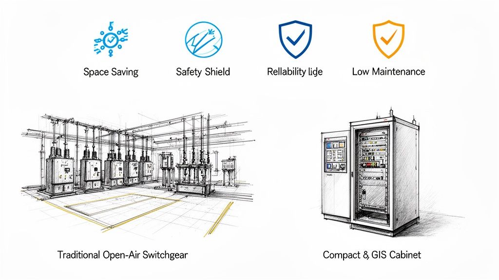
This incredibly compact, modular design delivers a few powerful advantages:
Massive Space Savings: GIS can be installed indoors, underground, or tucked away in tight industrial spaces where a traditional AIS substation simply wouldn't fit.
Unmatched Reliability: The sealed, controlled environment protects all the internal components from the outside world. Dust, moisture, salt spray, and other contaminants can't get in, leading to a much longer service life and fewer outages.
Superior Safety: With all live parts completely enclosed and grounded, the risk of accidental contact for personnel is virtually eliminated.
The market's growth tells the story. Valued at USD 22 billion in 2022, the global gas insulated switchgear market is on track to hit an incredible USD 55.8 billion by 2034. As cities expand and industries modernize, the demand for efficient, space-saving power infrastructure is only going up. You can dig deeper into these market trends for gas insulated switchgear over at gminsights.com.
The choice between GIS and AIS is a fundamental one that reshapes the entire approach to a project. It transforms a major land-use problem into a straightforward architectural one, opening up new possibilities for development in constrained areas.
GIS technology is a cornerstone of modern electrical substation design, allowing more power to be delivered more reliably in less space. From data centers and manufacturing plants to urban high-rises, GIS provides a tough, dependable solution where both performance and footprint are non-negotiable.
GIS vs AIS At a Glance
To put it all in perspective, here's a quick comparison of the two technologies. While both serve the same fundamental purpose of controlling and protecting electrical circuits, their design philosophies are worlds apart.
Ultimately, GIS represents a more advanced, contained, and robust approach to switchgear, trading a higher upfront cost for long-term reliability, safety, and a much smaller physical presence.
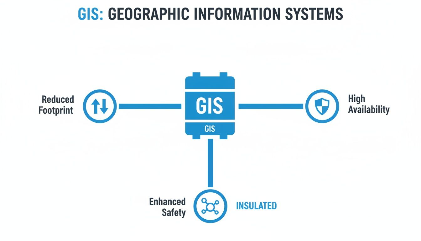
Understanding What’s Inside a GIS System
To really get what makes gas-insulated switchgear so different, you have to look inside that sealed, metal enclosure. It’s not just a box; it's a precisely engineered ecosystem where every component works together to control and protect high-voltage circuits. Think of it as a specialized crew operating in a perfectly controlled environment.
Each part is designed for maximum performance and a long service life, all contained within a single housing filled with an insulating gas. This fundamental design is the secret behind GIS's compact size, incredible reliability, and enhanced safety.
The image below sums up how these core principles translate into real-world benefits.
As you can see, the superior insulation is the key—it enables everything else, from the smaller footprint to rock-solid reliability. Now, let’s unpack the components that make it all happen.
The Protective Core: Circuit Breaker and Switches
The circuit breaker sits at the very heart of the switchgear. It's the system's first line of defense, designed to slam the door on electricity flow in milliseconds when it detects a fault like a short circuit. Inside a GIS, this all happens within the insulating gas, which is exceptionally good at extinguishing the massive electric arc that forms when a high-voltage circuit is broken.
But the breaker doesn't work alone. Two other switches are crucial for safe operation and maintenance:
Disconnectors (or Isolators): These create a clear, physical air gap in the circuit for total isolation. They’re only operated when the circuit is already de-energized, giving crews a visible guarantee that a piece of equipment is safely disconnected before they start work.
Earthing Switches (or Grounding Switches): Once a section is isolated by the disconnector, this switch connects the conductors directly to the ground. It’s a non-negotiable safety step that drains any residual charge and prevents induced voltage from becoming a hazard to personnel.
The Insulating Medium: The Secret Sauce
The real star of the show in a gas insulated switchgear system is the gas filling the enclosure. For many years, that gas was Sulfur Hexafluoride (SF6), a synthetic compound with incredible dielectric strength—basically, its ability to stop electricity from arcing where it shouldn't. To put it in perspective, SF6 is roughly 2.5 times more effective as an insulator than pure nitrogen and lightyears ahead of air.
The catch? SF6 is also a powerful greenhouse gas. With environmental regulations becoming stricter, the industry is quickly moving toward SF6-free alternatives. These "green" gases, like fluoronitrile-based mixtures or even highly pressurized clean air, offer similar insulating performance with a much, much smaller environmental footprint.
The insulating gas is the game-changer that allows for such a dramatic size reduction. By preventing arcs between live parts, it removes the need for the wide, open-air gaps you see in conventional switchgear. This lets engineers pack everything closer together, making the whole assembly smaller and far more robust.
The Monitoring and Measurement Tools
You can't control what you can't measure. That’s where instrument transformers come in—they are the eyes and ears of the GIS, constantly monitoring the system's vital signs.
You'll always find two main types:
Current Transformers (CTs): These devices safely measure the massive currents flowing through the conductors. They "step down" the current to a low, manageable level that can be read by protective relays and meters without vaporizing them.
Voltage Transformers (VTs): In the same way, VTs measure the extremely high system voltage, reducing it to a standardized, low value that monitoring and protection equipment can safely handle.
When you put it all together—the breakers, the switches, the gas, and the transformers—you get a completely self-contained and highly integrated system. Every single part is optimized to function perfectly within that controlled gas environment, achieving a level of performance and reliability that's tough for traditional, air-insulated gear to match. This tight integration is what makes gas-insulated switchgear the go-to choice for so many critical applications.
Why GIS Is a Smarter Choice for Industrial Operations
Picking the right switchgear isn't just a technical detail—it's a strategic decision that ripples through your entire operation, impacting efficiency, safety, and your bottom line. For any industrial facility, gas-insulated switchgear (GIS) makes a compelling business case by turning its sophisticated design into real-world, tangible benefits. This is about more than just managing power; it’s about optimizing your whole operational environment.
Let’s dig into the four key advantages that make GIS the go-to choice for plant engineers, project managers, and operations leaders who expect more from their critical infrastructure.
Free Up Your Most Valuable Asset: Space
In any industrial plant, floor space is gold. Every square foot tied up by non-production equipment is a missed opportunity for revenue-generating machinery or a more efficient workflow. This is where the compact nature of gas-insulated switchgear delivers its most immediate and striking advantage.
Because all its key components are sealed inside a gas-filled tank, a GIS unit can be up to 90% smaller than its air-insulated cousins.
This isn't just a minor perk; it's a strategic game-changer. It can be the deciding factor that allows a facility expansion to move forward instead of stalling due to site constraints. For a packed manufacturing floor, it could free up enough room for an entire new production line, directly boosting output and profitability.
Elevate Plant and Personnel Safety
Safety is absolutely non-negotiable in an industrial setting, and GIS is fundamentally built for it. Traditional air-insulated switchgear often has exposed live conductors, which poses a constant risk of accidental contact for any personnel working nearby.
With GIS, every live component is completely contained within a grounded metal enclosure. This design all but eliminates the risk of electric shock, making it an inherently safer technology for environments where people are working in close proximity to high-voltage equipment.
The sealed-for-life design of gas-insulated switchgear creates a controlled internal environment that is immune to external factors. This not only enhances reliability but also creates a formidable barrier between high-voltage electricity and the people who work around it every day.
This built-in safety shield reduces the chance of accidents and simplifies critical lockout-tagout procedures, leading to a more secure and efficient workplace. It also means the equipment is protected from accidental bumps from forklifts or other machinery, further protecting your operations.
Achieve Superior System Reliability
Industrial processes live and die by a constant, uninterrupted flow of power. Unplanned downtime can rack up thousands of dollars in losses every single minute, which puts equipment reliability at the very top of the priority list.
The sealed design of gas-insulated switchgear is its greatest strength. It essentially creates a fortress, shielding all critical internal parts from the harsh realities of an industrial plant.
Immunity to Contaminants: Dust, moisture, corrosive chemicals, and other particles common in industrial settings simply can't get inside to degrade the components.
Stable Performance: The controlled gas atmosphere provides consistent insulating performance, no matter what the external humidity or altitude is doing—factors that can easily affect air-insulated gear.
Fewer Outage Risks: This protection dramatically cuts down the risk of flashovers and faults caused by environmental contamination, giving you significantly higher uptime for your most critical processes.
Minimize Maintenance and Lower Lifecycle Costs
While the initial price tag for GIS can be higher, its long-term economic advantages are undeniable. The equipment is engineered for a service life of 30 to 40 years with very little intervention needed. Since the internal parts aren't exposed to environmental wear and tear, the need for routine cleaning and inspection is drastically reduced.
This all translates to fewer planned shutdowns, lower labor costs for maintenance, and a much smaller spare parts inventory to manage. When you look at the total cost over the equipment's entire lifecycle, these savings in operational expenses often make gas-insulated switchgear the more cost-effective solution. This superior technical design is precisely why GIS is a cornerstone of modern power infrastructure. You can find more insights on the global GIS market over at techsciresearch.com.
While GIS is a powerhouse for high-voltage distribution, it often works alongside other key equipment. To see how it fits into the bigger picture, check out our guide comparing motor control centers vs. switchgear.
How to Specify and Procure the Right GIS Solution
Picking the right gas-insulated switchgear isn't just a purchase; it's a major investment in your electrical system's future. To get it right, you have to look beyond the basic voltage rating and dig into a detailed specification process. It’s all about balancing technical muscle, lifecycle costs, and what the future might throw at you.
Let’s walk through a framework that helps engineers and procurement managers make a truly informed decision, not just a quick one.
Defining Your Technical Specifications
The first step is getting crystal clear on your core electrical and physical needs. This is about more than just the system voltage—it's about deeply understanding the real-world demands the GIS will face every day and during a worst-case scenario fault.
Think of your technical spec sheet as the blueprint for the entire project. If it's vague, you're inviting mismatched quotes and costly delays. You need to nail down every critical parameter.
Key electrical numbers you absolutely must define include:
Rated Voltage and Frequency: The fundamentals, like 145 kV at 60 Hz.
Rated Continuous Current: The absolute maximum current the main components can handle non-stop without breaking a sweat.
Short-Circuit Withstand Current: The gut-punch of a fault current the GIS has to survive without damage for a specific time, usually 1 or 3 seconds.
Basic Insulation Level (BIL): This proves the gear can handle massive voltage surges from things like lightning strikes or other switching events on the grid.
But don't stop there. You have to consider the physical world your GIS will live in. Is it going into a brand-new concrete building, a compact e-house, or being squeezed into a tight basement? Get the tape measure out. Document the exact footprint available, paying close attention to height limits and access routes needed for both installation and future maintenance.
Evaluating the Insulation Medium
For decades, SF6 gas was the undisputed king of insulation. But the world is changing. Environmental regulations are getting tighter, and that's pushing SF6-free alternatives from a "nice-to-have" to a "must-consider."
The EU, for instance, is already moving to phase out SF6 in new switchgear, with the first major deadline hitting in 2026 for medium-voltage equipment. That’s a clear signal of where the entire industry is headed.
When you're talking to potential suppliers, press them on the gas issue:
SF6-Free Options: Do they have field-proven alternatives? Are they using modern gas mixtures based on fluoronitriles or even just clean air? Ask for case studies and operational history.
Global Warming Potential (GWP): Get the numbers. Compare the GWP of their proposed alternative directly against SF6. Today's best options can slash GWP by over 99%.
Gas Handling: What’s the real story on handling and recycling the new gas? What special equipment or training is needed for installation and eventual decommissioning?
Opting for an SF6-free solution today is a smart move. It effectively de-risks your investment against future carbon taxes or outright bans, protecting your asset for the long haul.
GIS Specification Checklist
To make sure you cover all your bases, a detailed checklist is your best friend. It transforms your requirements from a simple list into a robust specification that suppliers can quote against accurately. Here’s a practical template to get you started.
Parameter
Key Considerations
Example Specification
Voltage & Current
System voltage, frequency, continuous current needs, and short-circuit withstand for 1s or 3s.
Rated Voltage: 145 kV; Rated Current: 2500 A; Short-Circuit: 40 kA for 3s.
Insulation Level (BIL)
Must withstand lightning and switching surges common to your grid environment.
Lightning Impulse (BIL): 650 kVp.
Insulating Medium
Is SF6 acceptable, or is an SF6-free alternative required? Consider GWP, handling procedures, and long-term viability.
Gas mixture with GWP < 1. Supplier to provide gas handling and lifecycle plan.
Footprint & Layout
Maximum allowable dimensions (L x W x H). Access requirements for installation and maintenance. Indoor or outdoor placement?
Indoor installation; Max footprint: 15m x 5m x 4m (L x W x H).
Configuration
Single busbar, double busbar? Number of incoming and outgoing feeder bays required.
Single busbar configuration; 2x Incoming Lines, 4x Transformer Feeders.
Maintenance Philosophy
Define expected maintenance intervals. Are sealed-for-life components a priority?
Minimal maintenance required; major inspection interval > 20 years.
Ambient Conditions
Operating temperature range, altitude, and seismic requirements for the installation site.
Temperature: -5°C to +40°C; Altitude: < 1000m; Seismic Zone 3 compliant.
Standards & Testing
Specify compliance with IEC or ANSI/IEEE standards. Mandate a full Factory Acceptance Test (FAT).
Compliance with IEC 62271-203. FAT to be witnessed by owner's engineer.
Using a structured checklist like this ensures nothing falls through the cracks and you get a GIS that’s perfectly suited for the job.
Looking Beyond the Price Tag to Total Cost
One of the biggest mistakes you can make is choosing a GIS based on the initial price tag alone. You have to think bigger. A true evaluation looks at the Total Cost of Ownership (TCO), and this is where GIS often shines, even if the upfront cost is higher.
Why? The incredibly compact footprint.
The decision to use GIS can reduce land acquisition or building construction costs so drastically that it more than offsets the higher equipment price. For urban projects or plant expansions, this factor alone can make GIS the most economically viable choice.
When you run the numbers for TCO, be sure to include:
Land and Civil Works: The smaller footprint means a smaller bill for real estate and construction. It’s that simple.
Installation and Commissioning: GIS modules are typically assembled and tested in the factory, which dramatically cuts down on the time and complexity of on-site work.
Maintenance Costs: The sealed-for-life design means far less maintenance. That translates to lower labor costs and less planned downtime over a 30-40 year service life.
Ensuring Compliance and Quality
Finally, you need to be uncompromising on quality assurance. Your GIS is a linchpin of your electrical system, and its reliability hinges on strict adherence to international standards and rigorous testing. Don't be shy about making demands.
Before you sign any contract, get clear, written answers to these questions:
Standards Compliance: Does the equipment fully comply with the relevant IEC or ANSI/IEEE standards for design, manufacturing, and testing? Ask for the specific standard numbers.
Factory Acceptance Testing (FAT): A comprehensive FAT is non-negotiable. It's your chance to verify the equipment performs as promised before it ever leaves the factory. To get a better handle on this, check out our guide on what a factory acceptance test checklist should cover.
Commissioning Support: What level of hands-on support will the supplier provide on-site? This includes installation supervision, gas filling, and the final commissioning tests to bring the system online.
By following this structured path—nailing down your technical needs, weighing the new gas alternatives, analyzing the total cost, and demanding tough quality checks—you can confidently choose a GIS that will deliver safety, reliability, and value for decades to come.
Getting GIS Installation and Maintenance Right
A gas-insulated switchgear system is built to last, often designed for a service life of 30 to 40 years. But getting there isn't a given. That kind of longevity depends entirely on a flawless installation and a smart, forward-thinking maintenance plan. This is the stage where your investment’s long-term reliability is truly locked in.
The initial setup is, without a doubt, the most critical phase in a GIS's entire life. Unlike its air-insulated cousins that are more forgiving, a GIS demands precision and a controlled environment. Any shortcut or mistake made here can plant a hidden problem that might not show itself for years.
Executing a Flawless GIS Installation
Putting together a GIS is less like construction and more like performing surgery. The whole point is to assemble the factory-built modules while keeping the insides completely pristine—free of any contaminants that could weaken the insulating gas.
A clean, dry, and controlled setting is non-negotiable. Dust, moisture, or even tiny metallic shavings can cripple the dielectric strength of the SF6 gas. That’s why the assembly is often done inside temporary clean rooms or under positive-pressure tents right on the construction site.
The integrity of a GIS is established the moment its compartments are sealed. A single foreign particle or a trace of moisture introduced during assembly can become a nucleation point for partial discharge, slowly degrading the insulation and leading to a potential failure down the road.
Beyond the environment, the people doing the work are just as crucial. Handling the gas—filling the compartments with SF6 or an alternative—is a job for certified technicians. They use specialized gear to make sure the gas is at the perfect density and purity, because even small deviations can throw off performance. This is the kind of precision that separates a world-class installation from a future headache.
Pre-Commissioning Tests: The Final Gatekeeper
Before a new GIS system ever sees a live current, it has to pass a tough battery of pre-commissioning tests. Think of these as the final quality check, proving that the on-site assembly went perfectly and the gear is ready to do its job.
Here are the must-pass checks:
High-Voltage Withstand Test: This is where we apply a high voltage for a specific time to make sure the insulation system is solid and that no hidden defects from shipping or assembly exist.
Gas Quality and Leak Checks: Technicians verify the purity and moisture content of the gas. They also run highly sensitive leak detection tests on every flange and joint to ensure the system is sealed tight, targeting leakage rates below 0.1% per year.
Operational Checks: Every moving part—circuit breakers, disconnectors, earthing switches—is operated multiple times. This confirms they all move smoothly and within the manufacturer's specified timings.
Long-Term Care: What "Maintenance-Free" Really Means
You’ll often hear GIS described as "maintenance-free," but that term can be a bit misleading. It doesn’t mean you can just install it and walk away. What it really means is that GIS requires far less invasive maintenance than air-insulated switchgear. The focus shifts from constant cleaning and parts replacement to smart, non-invasive monitoring.
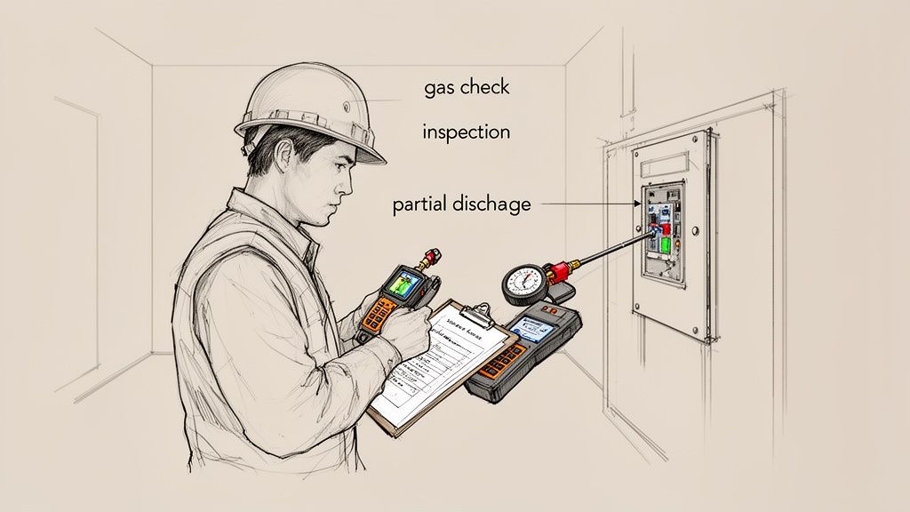
Routine care for a GIS comes down to a few key activities. The most basic is keeping a close eye on the gas density. Modern systems have sensors that constantly track the temperature-compensated pressure, giving you an early warning if a leak develops.
Periodic visual inspections are also essential. A simple walk-through can catch a lot—signs of corrosion on the enclosure, checking that control circuits are in good shape, and making sure all monitoring gauges are working properly.
Advanced diagnostics are where modern GIS care really shines. Techniques like Partial Discharge (PD) monitoring can detect tiny electrical sparks inside the insulation, which are often the very first sign of a developing fault. Similarly, acoustic monitoring can pick up on unusual mechanical vibrations from moving components. This condition-based approach means you schedule work when it's actually needed, not just because the calendar says so, maximizing uptime and helping your GIS deliver reliable power for decades.
Common Questions About Gas Insulated Switchgear
As gas insulated switchgear starts showing up more and more in critical power systems, it’s only natural for engineers, project managers, and facility owners to have questions. This technology is a different beast compared to traditional switchgear, and getting a handle on the specifics is key to making the right call.
We’ve rounded up some of the most common questions we hear about GIS. The goal here is to give you clear, straightforward answers that cut through the jargon and build on what we've already covered.
What Is the Primary Difference Between GIS and AIS?
It all comes down to the insulating medium. Think of it like this: traditional Air Insulated Switchgear (AIS) uses the air in the room to keep high-voltage components from arcing over. Since air isn't a fantastic insulator, you need a lot of space—big physical gaps between conductors. This is why AIS lineups are so massive.
Gas Insulated Switchgear (GIS), on the other hand, puts all its live components inside a sealed, grounded metal enclosure filled with a special insulating gas. This gas is a powerhouse insulator, with a much higher dielectric strength than air. That lets you safely place components incredibly close together.
The result? A GIS assembly can be up to 90% smaller than its air-insulated equivalent. It’s a game-changer for tight spaces like urban substations, crowded industrial plants, or offshore platforms.
Are There Environmental Concerns with the SF6 Gas Used in GIS?
Yes, that’s a fair question and a big topic in the industry. The gas traditionally used, Sulfur Hexafluoride (SF6), is an extremely potent greenhouse gas. To put it in perspective, its global warming potential (GWP) is about 24,300 times higher than carbon dioxide.
But it’s important to see the whole picture. Modern GIS units are built as sealed-for-life systems. They come with factory-guaranteed leakage rates that are incredibly low—typically less than 0.1% per year. The industry is also heavily regulated on how to handle, recycle, and dispose of SF6 to keep it out of the atmosphere.
The real story, though, is the rapid shift toward SF6-free alternatives. These "green" gases deliver the same great insulating performance but slash the global warming potential by over 99%. This move essentially neutralizes the long-term environmental footprint for new GIS installations.
This isn't just a voluntary trend; it's becoming law. The EU, for instance, is set to phase out SF6 in most new medium-voltage switchgear as early as 2026.
Is GIS More Expensive Than Traditional Switchgear?
If you only look at the initial price tag, yes, GIS equipment usually has a higher upfront cost than comparable AIS. But that's a very narrow way to look at it. A smart financial analysis always considers the total cost of ownership (TCO).
Over its lifespan, GIS often works out to be the more economical choice. The massive reduction in footprint alone can save a fortune in land or building costs, especially in pricey urban areas where every square foot counts.
On top of that, GIS is practically maintenance-free. With all the critical parts sealed away from dust, moisture, and corrosive air, you get some major long-term benefits:
Lower operational and labor costs
Far less planned downtime for cleaning and upkeep
A longer, more reliable service life, often 30-40 years
When you run the numbers on all these factors, the GIS investment looks much more attractive and frequently beats the lower sticker price of AIS in the long run.
What Are the Typical Applications for Gas Insulated Switchgear?
GIS is incredibly versatile, but it really shines in places where space is tight, reliability is an absolute must, or the environment is just plain nasty.
Its tough, compact design makes it the go-to solution for a huge range of critical infrastructure.
You’ll find it in:
Urban Power Substations: Perfect for tucking into buildings or even underground where real estate is scarce.
Power Generation Plants: Including wind and solar farms where a small, reliable footprint is essential.
Heavy Industrial Facilities: Think manufacturing plants, oil and gas rigs, and mines where dust, chemicals, and moisture would destroy conventional gear.
Data Centers: Where an uninterruptible power supply is the lifeblood of the business.
Transportation Infrastructure: Used extensively in railway systems and airports that can't afford downtime.
The plug-and-play, modular nature of GIS also makes it ideal for prefabricated e-houses and mobile substations that need to be deployed and energized fast.
Navigating the complexities of modern electrical systems requires a partner with deep expertise. At E & I Sales, we specialize in designing and integrating reliable power distribution and motor control solutions, from MV switchgear to custom UL control panels. If you're planning a project that demands performance and efficiency, our team has the field experience to deliver a solution that meets your exact specifications.
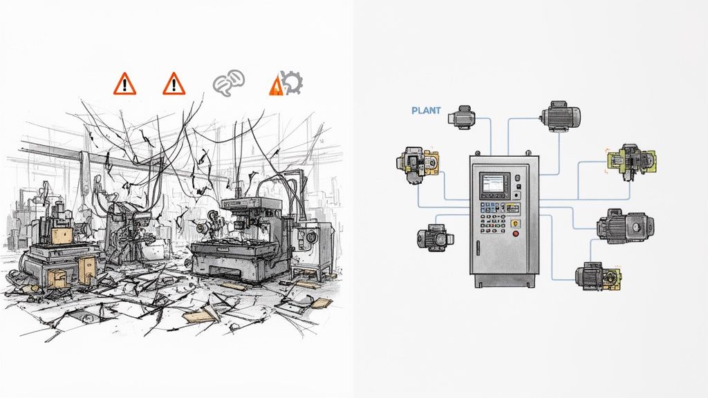
Picture this: your big plant expansion project is dead in the water. Why? Because the new VFDs from one vendor refuse to talk to the PLCs from another. It's not just a technical snag; it's a full-blown operational crisis, leading to downtime, safety concerns, and a budget that's spiraling out of control.
If that sounds familiar, you already know the truth: systems integration isn't just an IT problem, it's a core business strategy.
Why Strategic Systems Integration Is a Game-Changer
When done right, professional systems integration services take all those disparate pieces of equipment—motor controls, automation hardware, power distribution gear—and make them work together as a single, well-oiled machine. Too many project managers treat integration as an afterthought, something to bolt on at the end. That’s a mistake. The smart ones know it's the foundation of operational excellence. It’s what separates a random collection of machines from a truly unified production line.
This guide isn't about textbook definitions. It’s a practical roadmap for using integration to turn that potential chaos into a real competitive advantage. My goal here is to give you, the engineer or buyer on the ground, the tools you need to specify, select, and manage these critical services effectively.
The Business Case for Getting It Right
In an industrial plant, integration failures hit the bottom line—hard and fast. When a new variable frequency drive (VFD) can't communicate with the central PLC, or a motor control center (MCC) isn't properly tied into the SCADA system, the whole process can just stop. These aren't minor bugs; they're fundamental breakdowns.
This is where a good systems integrator proves their worth, delivering tangible results that you can see in your P&L. The real benefits are clear:
Slash Operational Downtime: Systems built to work together are just more reliable. A unified control architecture means you can find and fix problems faster, getting equipment back online in minutes, not hours.
See Everything, Control Everything: When all your components are speaking the same language, you finally get a complete picture of your operation. This is gold for making smarter decisions, implementing predictive maintenance, and optimizing your processes.
Boost Safety and Compliance: A qualified integrator is your best defense against non-compliance. They ensure every part of the system, like UL 508A for control panels, meets the right standards and that safety circuits are rock-solid.
Build for the Future: A smart integration plan always looks ahead. A well-designed system makes it far easier to add capacity or upgrade technology later without having to rip everything out and start over.
People often think integration is just about connecting a few wires. The reality is, it’s about creating a seamless flow of data and control that directly supports your business goals, whether that’s boosting throughput or cutting energy costs.
Bridging the Physical and Digital Worlds
Modern plants are a complex dance between physical machinery (motors, pumps, conveyors) and the digital brains that run them. A systems integrator is the choreographer making sure that dance is perfectly synchronized.
This involves a lot more than just software. While many resources talk about connecting business apps—and for a deeper dive on that, you can check out this overview of software integration services—our world is different.
Here on the plant floor, the focus is on making heavy iron work together intelligently. In the sections that follow, I'll walk you through the nitty-gritty of managing these projects to make sure your investment pays off.
Defining Your Project Scope and Technical Needs
A vague project scope is the single biggest threat to your budget and timeline. I’ve seen it happen time and again—ambiguity leads to misunderstandings, costly change orders, and a lot of finger-pointing when things go sideways.
A successful project always starts with a crystal-clear Scope of Work (SOW). Think of this document as the definitive blueprint for everyone involved. It’s not just paperwork; it’s your first and best defense against scope creep.
When you hand a detailed SOW to potential systems integration services providers, you empower them to give you accurate, competitive bids. They can see exactly what you need, from hardware preferences to performance targets, which kills the guesswork. The result is a much smoother project, from design to commissioning, because you set clear expectations right from the start.
From Business Goals to Technical Specs
Your SOW has one primary job: translate high-level business objectives into concrete technical requirements an integrator can actually build from. It’s not enough to say you want a "more efficient system." You have to get specific and quantify what that means.
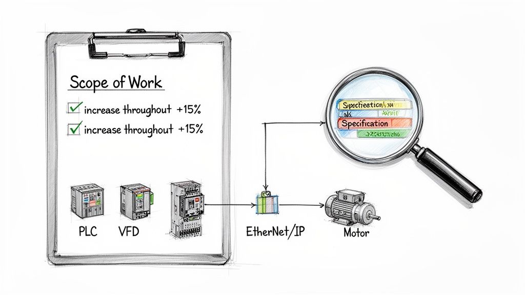
Start by defining your operational goals in measurable terms. Are you trying to boost production, cut down cycle times, or improve energy efficiency? A well-defined goal immediately gives the project direction.
For instance, a goal like "increase conveyor throughput by 15%" is infinitely more useful than just "make the conveyor faster." This specific target directly informs decisions about motor sizing, VFD programming, and PLC logic. These are the kinds of details any firm providing industrial controls and automation solutions needs to design the right system.
Make sure your SOW nails down these core elements to eliminate any confusion:
Operational Objectives: State the business or production goals clearly. Use numbers and metrics whenever you can.
Hardware and Software Specs: List any required or preferred manufacturers for PLCs, VFDs, HMIs, and other key components. If your plant has standardized on a particular platform, say it loud and clear.
Communication Protocols: Define the network architecture. Does the system need to communicate over EtherNet/IP, PROFINET, Modbus TCP, or something else?
Compliance and Standards: This is non-negotiable. List all required industry standards, like UL 508A for control panels, and include any of your own corporate safety or engineering standards.
Building a Comprehensive Scope of Work
A truly effective SOW leaves no room for interpretation. It’s a detailed document that covers every phase of the project, from the parts list to the final documentation you expect to receive. It's the ultimate checklist to ensure you get exactly what you paid for.
A strong SOW isn't about micromanaging your integrator. It’s about creating a shared understanding of success. When both parties know exactly what the finish line looks like, you’re far more likely to get there on time and on budget.
The table below breaks down the key components every industrial integration SOW should have. Use this as a guide to make sure you've covered all your bases before sending the project out for bid. This level of detail helps potential partners understand the full picture, which leads to better questions and more accurate proposals.
Key Components for a Systems Integration SOW
Use this checklist to ensure your Scope of Work is comprehensive, clear, and provides all the necessary details for accurate integrator bidding.
Component
What to Include
Practical Example
Project Overview
A high-level summary of the project's purpose and the problem it solves.
"Upgrade the main packaging line's control system to increase throughput by 15% and replace obsolete PLC hardware."
Mechanical Scope
Details on physical equipment being controlled or installed.
"Integrator to provide controls for a new conveyor system (Model XYZ). All mechanical installation by others."
Electrical Scope
Power requirements, source of power, and panel specifications.
"The new control panel will be fed from MCC-04, breaker 22. Panel must be UL 508A certified and include a main disconnect."
Control Narrative
A detailed, step-by-step description of how the system should operate.
"When the start button is pressed, the conveyor motor will ramp up to 60 Hz over 5 seconds. A photo-eye will count boxes."
Deliverables
A list of all documentation to be provided upon completion.
"As-built electrical drawings in AutoCAD format, PLC and HMI source code, a complete Bill of Materials, and O&M manuals."
Putting in the time to create a thorough SOW upfront is one of the best investments you can make. It sets the stage for a successful partnership and ensures the systems integration services you receive are perfectly aligned with your operational needs, preventing costly surprises down the road.
How to Select the Right Integration Partner
Choosing a partner for your systems integration services based on the lowest bid is one of the oldest, and most expensive, mistakes in the book. It’s a classic trap. That low initial quote often balloons with change orders, unexpected downtime, and non-existent support when you need it most.
The real goal isn't to find the cheapest contractor. It’s to find a true partner who delivers long-term value and reliability you can count on.
This means you need a solid evaluation process that goes way beyond the price tag. You’ve got to dig into a potential partner’s technical chops, their real-world industry experience, how they manage projects, and their safety culture. A slick proposal is one thing; proven execution is what actually matters.
Beyond the Bid Price: Technical Expertise
Your first filter should always be technical competence. It's non-negotiable. Does the integrator have deep, hands-on experience with the specific hardware and software platforms humming away in your facility? This is absolutely critical for core components like PLCs and VFDs.
When an integrator is a certified partner with brands like Rockwell Automation or Siemens, it's more than just a piece of paper. It means they have a direct line to technical support, specialized training, and product roadmaps that a generalist simply can't access. That inside track can be a lifesaver when you're troubleshooting a complex issue during commissioning.
When you're vetting potential partners, ask specific, probing questions about their experience:
Platform Proficiency: Get them to talk about recent projects using the exact PLC family you plan to use (e.g., ControlLogix, S7-1500).
Network Knowledge: How much experience do they have with the industrial protocols in your scope, like EtherNet/IP or PROFINET? Ask how they guarantee network reliability.
In-House Capabilities: Find out what work they do themselves versus what they subcontract. Do they have an in-house UL 508A panel shop? Keeping programming and engineering in-house almost always leads to better quality control and a more cohesive final product.
The real value of a top-tier integration partner isn't just their ability to follow a scope of work. It's their capacity to spot potential problems you haven't thought of and recommend better, more reliable solutions based on their deep product knowledge.
Evaluating Industry Experience and Past Performance
General automation experience is good. But direct experience in your industry is a whole lot better.
An integrator who understands the unique headaches of a food and beverage plant—like clean-in-place requirements and traceability—will deliver a far better result than one who has only ever worked in automotive manufacturing. Relevant experience means they already speak your language and won't be learning on your dime.
Checking references is a step you cannot skip. And don't just ask for a list of happy clients. Ask specifically for contacts from projects that were similar in scope and complexity to yours.
When you call those references, ask the tough questions:
How did the integrator handle unexpected curveballs or scope changes?
Was the project documentation—drawings, code, manuals—thorough and accurate?
Would you hire them again for another critical project? The answer to that last one tells you everything you need to know.
A site visit can also be incredibly revealing. Ask to tour their facility, and more importantly, their panel shop. A clean, organized shop with clear quality control processes is a huge indicator of a disciplined, professional organization. A messy, chaotic shop is a major red flag. If you want to dive deeper, you can learn more about the key characteristics of an effective industrial automation system integrator on our blog.
The Value-Based Decision
Ultimately, your decision has to come down to value, not just cost. A slightly more expensive partner with deep expertise, a proven track record, and robust support systems will almost always deliver a lower total cost of ownership. Their systems are simply more reliable, easier to maintain, and are backed by a team you can count on.
Create a simple evaluation matrix to score potential partners objectively across your key criteria. This is a great way to move the conversation away from a single price point and toward a more balanced, value-focused decision.
Your future self will thank you when the system is running flawlessly years from now.
Managing the Project from Kickoff to Commissioning
You’ve signed the contract and selected your integration partner. Great. Now the real work starts.
Signing that dotted line isn't the finish line; it’s the starting gun. If you want this project to land on time and on budget, you have to stay actively engaged. A hands-off approach is a recipe for missed deadlines, scope creep, and a final product that doesn’t quite hit the mark.
Think of yourself as the project's co-builder. Your integrator handles the technical heavy lifting, but your job is to provide clear direction, fast feedback, and firm approvals. We can break this entire process down into a few key phases, each with its own critical milestones.
Setting the Stage with a Strong Kickoff
The project kickoff meeting is more than just a formality—it’s your first and best chance to set the tone for the entire engagement. This is where you get both teams in a room and translate that written Scope of Work into a shared game plan.
During this meeting, you need to lock down a few non-negotiable processes. Getting these things right from day one will save you a world of headaches later.
Establish a Single Point of Contact: Designate one person on your team and one on the integrator’s to be the official communication channel. This prevents crucial information from getting lost in a flurry of emails between different engineers and managers.
Nail Down the Change Order Process: Let's be realistic—scope creep happens. But it doesn't have to create chaos. Define a formal, written process for how any changes are requested, quoted, approved, and tracked. No "oh, by the way" additions.
Confirm the Project Schedule: Go through the timeline milestone by milestone. Pay special attention to the critical path and identify anything that depends on your team, like getting the integrator access to the facility or digging up old electrical drawings.
The Design and Submittal Phase
With the ground rules set, the integrator’s engineering team gets to work turning your operational needs into detailed electrical designs. This stage ends with the delivery of the design submittal package. This is a huge milestone. Your sign-off here gives them the green light to start ordering parts and building panels.
This package is your first tangible look at the system. It’ll include things like electrical schematics, panel layout drawings, and a detailed Bill of Materials (BOM). Don't just skim it. Scrutinize every single page. A change on paper costs next to nothing. A change after a control panel has been wired can cost thousands and delay the project for weeks.
Treat the design submittal like the final blueprint for a house. Once you sign off, you’re saying, "Yes, this is what I want you to build." You are confirming that the design will meet your operational and technical needs.
The Power of Factory Acceptance Testing
Before a single piece of equipment ships to your site, it needs to be put through its paces at the integrator's shop. This is called the Factory Acceptance Test (FAT), and it is arguably the single most important risk-mitigation step in the entire project.
The FAT is your chance to see the system run in a controlled environment. You can find software bugs, test the HMI screens, and request changes before that panel ever leaves their facility. A well-run FAT can catch and fix up to 90% of potential issues before they have a chance to cause massive delays during on-site commissioning.
You should see the panel fully powered up, connected to simulators that mimic your real-world devices. You'll get to watch the PLC logic execute and make sure the operator interface is intuitive. To make sure you cover all your bases, a solid checklist is a must. You can use our Factory Acceptance Test checklist as a starting point to build your own.
From Installation to Final Acceptance
Once the FAT is successfully in the rearview mirror, the system is shipped to your facility for installation. The integrator will handle the physical work of mounting panels and pulling wires, but your role is to clear the path for them. That means coordinating with other trades, ensuring site access, and making sure everyone follows your plant’s safety rules.
After the hardware is in place, the Site Acceptance Test (SAT) begins. This is the moment of truth. While the FAT tested the system in isolation, the SAT proves it works with your actual machinery. It's the final validation that the integrator has delivered on their promises, leading to the final project sign-off and official handover.
Mitigating Common Risks and Measuring True ROI
Let's be realistic: every industrial project has potential landmines. Even with the best planning, things can go sideways. While bringing in professional systems integration services is a huge step in the right direction, you can't just set it and forget it. You need to be aware of the common pitfalls to manage them proactively instead of just reacting when things catch fire.
Two of the biggest project-killers I see time and again are scope creep and interoperability failures.
Scope creep is that slow, insidious addition of "just one more thing" that wasn't in the original plan. It'll quietly bleed your budget dry. Your best defense is a rock-solid change order process you establish right at kickoff. Then there are the interoperability nightmares, where expensive gear from different vendors simply refuses to talk to each other. This is where a detailed design review and a comprehensive Factory Acceptance Test (FAT) become your most valuable assets.
Proper risk management is non-negotiable for getting these projects over the line on time and on budget. For those of us dealing with the software side of automation, the principles of software project risk management offer a really solid framework for spotting trouble before it gets out of hand.
Practical Strategies for Risk Mitigation
Anticipating problems is half the battle won. A proactive approach isn't about creating hundred-page risk registers; it's about practical, on-the-ground tactics that keep the project from veering off course.
Here are a few strategies that have proven their worth in the field:
Implement a RACI Chart: A Responsibility Assignment Matrix (RACI) chart is a simple but powerful tool. It makes it crystal clear who is Responsible, Accountable, Consulted, and Informed for every critical task. This eliminates confusion and prevents things from falling through the cracks because everyone thought someone else was handling it.
Plan Phased Rollouts: If you're upgrading a system that touches multiple production lines, a "big bang" go-live is just asking for trouble. A phased rollout, where you tackle one area at a time, is much smarter. It minimizes disruption to operations and lets your team learn and adapt in a more controlled environment.
Prioritize Communication: Get regular, mandatory project meetings on the calendar and stick to them. A fixed agenda creates a predictable rhythm and ensures that small issues get aired out and solved before they fester into major roadblocks.
The point of risk management isn't to create a perfect, problem-free project. That's a fantasy. The goal is to reduce uncertainty so that when issues inevitably pop up, you have a plan ready to go, minimizing the hit to your schedule and budget.
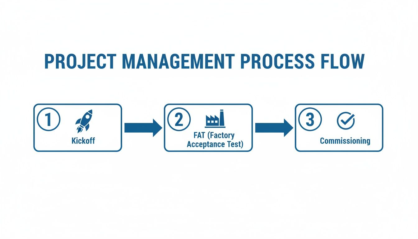
This diagram shows a typical high-level project flow, highlighting the key checkpoints where you should be assessing risk.
Each of these stages—from the initial kickoff to the final commissioning—is a crucial chance to identify and squash risks before you move on.
Calculating the True Return on Investment
Okay, the project is done, the system is humming along, and now the front office wants to talk numbers. Specifically, Return on Investment (ROI). Too often, people only look at the initial project cost versus the immediate labor savings. This view is incredibly shortsighted and completely misses the real value of a well-integrated system.
To build a compelling business case, you have to look at the full picture. The capital outlay is just one piece of the puzzle. The true value is what you unlock over the long haul through better performance across the board.
Think about these less-obvious, but hugely impactful, metrics when you're calculating your real ROI:
Reduced Unscheduled Downtime: Do the math on what an hour of downtime costs on that production line. A 10% reduction in unplanned stops can easily translate into hundreds of thousands of dollars saved over a year.
Improved Energy Efficiency: Modern VFDs and integrated motor controls can slash energy consumption. Pull the utility bills from before and after the upgrade—the numbers will speak for themselves.
Lower Long-Term Maintenance Costs: When you have a standardized system with quality parts and complete documentation, your maintenance team can troubleshoot issues faster. That's a direct reduction in maintenance labor costs, year after year.
When you start quantifying these tangible benefits, you can clearly show how a strategic investment in quality systems integration services pays for itself many times over. It stops being an "expense" and becomes what it truly is: a powerful engine for long-term profitability.
When you're diving into the world of systems integration services, a lot of questions come up. It's only natural. Getting straight answers is the key to making a good decision and keeping your project on track. Let's tackle some of the most common things people ask when they're looking to hire an integration partner.
What's the Difference Between a Systems Integrator and an EPC Firm?
This is a big one, and it’s all about project roles.
Think of a Systems Integrator (SI) as the specialist who handles the "brains" of the operation. Their entire world revolves around making the machinery do what it's supposed to do. We're talking PLC programming, SCADA systems, HMI development, and the networks that tie it all together. They are the control system experts.
An Engineering, Procurement, and Construction (EPC) firm, on the other hand, is the general contractor for the entire project. They have a much wider focus, managing everything from pouring the concrete and erecting the steel to the mechanical and structural engineering. In nearly every major project, the EPC firm will hire a specialized SI as a subcontractor to handle the automation and controls scope.
How Should We Decide Between Proprietary and Open-Source Technology?
This is a strategic fork in the road, and the choice you make will stick with you long after the integrator has packed up their tools.
Proprietary systems from a major vendor like Rockwell or Siemens offer a very streamlined experience. Everything is designed to work together, and you have a single number to call for support. The flip side? You can get locked into their ecosystem, which might limit your options and negotiating power down the road.
An open-source or multi-vendor approach gives you a ton of flexibility and often lets you shop around for more competitive pricing on individual components. The trade-off is that it can demand more heavy lifting during integration to make sure all the different pieces play nicely together. The right answer really depends on your team's in-house skills and how you plan to handle maintenance long-term. A good integrator won’t just tell you what to do; they’ll walk you through the pros and cons for your specific situation.
The decision between proprietary and open technology isn't just technical; it's a business decision. It directly impacts your future flexibility, your team's training needs, and the total cost of ownership for the life of the system.
What Level of Post-Project Support Should We Expect?
Don't ever let post-project support be an afterthought. This needs to be spelled out clearly in your contract before any work begins, because vague promises of "we'll be there for you" are a major red flag.
At the bare minimum, your agreement should specify a warranty period—typically one year—that covers any defects in the workmanship.
But a good contract goes further. It needs to detail specific response times for support calls and lay out the exact process for getting help. It’s also smart to talk about ongoing support options before you sign, like preventative maintenance contracts or remote monitoring services.
Finally, the project isn't truly done until you have the complete documentation package in hand. This is non-negotiable and must include:
Complete as-built electrical drawings
All PLC, HMI, and SCADA source code
Thorough training for your maintenance and operations staff
This is how you ensure your team is fully equipped to own, operate, and maintain the system for years to come without being totally dependent on the integrator.
At E & I Sales, we don’t just build systems; we build systems that last. We believe that providing the right documentation and support is just as important as the code we write. We combine deep product expertise with turnkey integration services to deliver reliable, code-compliant solutions that set your team up for long-term success.
Let's be honest, if you walked onto a factory floor and saw a separate, tangled mess of wires and control boxes for every single motor, you’d probably turn right back around. It would be a chaotic, unsafe, and downright impossible system to manage.
This is where the Motor Control Center, or MCC, comes in. Think of it as the central command hub for every motor-driven piece of equipment in your facility.
Decoding the Motor Control Center
At its core, an MCC is just a smart way of organizing things. It’s a large, free-standing metal cabinet that brings together all the starters, breakers, and other control gear for dozens or even hundreds of motors into one convenient location.
Instead of having controls scattered across the plant floor—one for that pump, another for this conveyor, a third for that fan—everything is neatly arranged in a single, safe enclosure. This centralization is the key.
The Apartment Building Analogy
The best way to understand an MCC is to picture a high-rise apartment building. The building itself is the MCC structure—a steel framework providing the main power feed and a safe place for everything to live.
Within this "building," you have:
The Main Power Bus: This is like the main utility line running up through the building, delivering power to every floor and every unit. It’s the electrical backbone.
Each Bucket: Think of these as the individual apartments. Every "bucket" is a self-contained, modular drawer that holds all the necessary controls for one specific motor—its starter, circuit breaker, and control wiring.
The Modular Design: Here’s the brilliant part. A technician can safely disconnect and pull out a single "apartment" (the bucket) to perform maintenance or repairs without cutting power to anyone else. The rest of the "tenants" (the other motors) keep running without interruption.
This simple concept—centralizing control while keeping it modular—is what makes the MCC an absolute game-changer in industrial environments. It takes a potential nightmare of distributed controls and turns it into a streamlined, safe, and easily serviceable system.
By organizing motor controls this way, facilities unlock massive gains in safety, troubleshooting time, and future scalability. It provides a clean, logical foundation for complex automation, making it infinitely easier to manage and expand your operations as your needs change. Now, let's open one up and see what’s inside.
A Look Inside the MCC: A Component Breakdown
To really get what an MCC is, you have to look past the steel doors and see how it's put together. The best way to think about it is like an electrical city. Power comes into town on a massive superhighway and gets routed through a structured grid of streets to reach every "house"—in this case, each individual motor. This brilliantly organized layout is what makes the MCC so powerful and reliable.
The whole journey starts with the main power bus. These are thick, heavy-duty bars of copper or aluminum that typically run horizontally across the top or back of the entire MCC lineup. This bus is the main artery, the electrical interstate, fed by an upstream transformer or switchgear. All the power for every single motor flows through here first.
From this main highway, power peels off onto smaller "exit ramps" called vertical bus bars. These bars run up and down inside each MCC section, acting as the local streets that deliver power directly to the individual motor control units stacked within. It's a clean, direct, and safe way to ensure every unit gets the juice it needs.
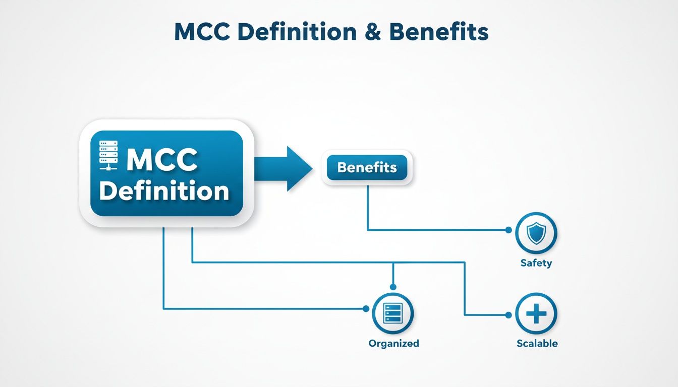
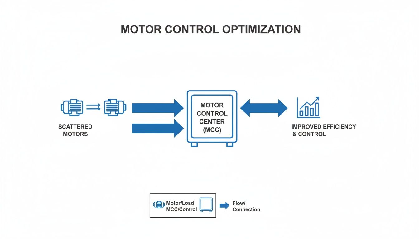
This centralized design isn't just neat and tidy; it delivers tangible benefits in the real world.
As you can see, organizing everything into one central hub directly translates to a safer, more scalable, and far more manageable system.
The Real Genius of the MCC: The "Bucket"
Now for the heart of the system: the individual units, which everyone in the industry calls “buckets.” Each bucket is a self-contained, removable drawer that holds all the gear needed to control and protect one motor. It’s a true plug-and-play design and the secret sauce behind the MCC's flexibility.
Think about it—if a component fails, you don't have to rewire anything in a live cabinet. A technician can de-energize that single bucket, pull it out, and slide a spare one in its place in minutes. This dramatically slashes downtime, which is a massive win in any production environment.
Let's unpack what you'll typically find inside one of these buckets. This table breaks down the key players and their roles, using a simple traffic analogy to make it clear.
Key Components Inside an MCC and Their Functions
Component
Primary Function
Analogy
Motor Starter
Safely starts and stops the motor, managing the initial inrush of current.
The On-Ramp/Off-Ramp that lets the car (motor) safely merge onto and exit the highway (circuit).
Overload Relay
Monitors motor current and trips if it draws too much power for too long.
A Traffic Cop monitoring speed. If a car goes too fast (overloads) for too long, it gets pulled over.
Circuit Breaker/Fuse
Provides instantaneous protection against short circuits or major faults.
A Guardrail. It does nothing until a catastrophic event (a crash/fault) happens, then it stops it cold.
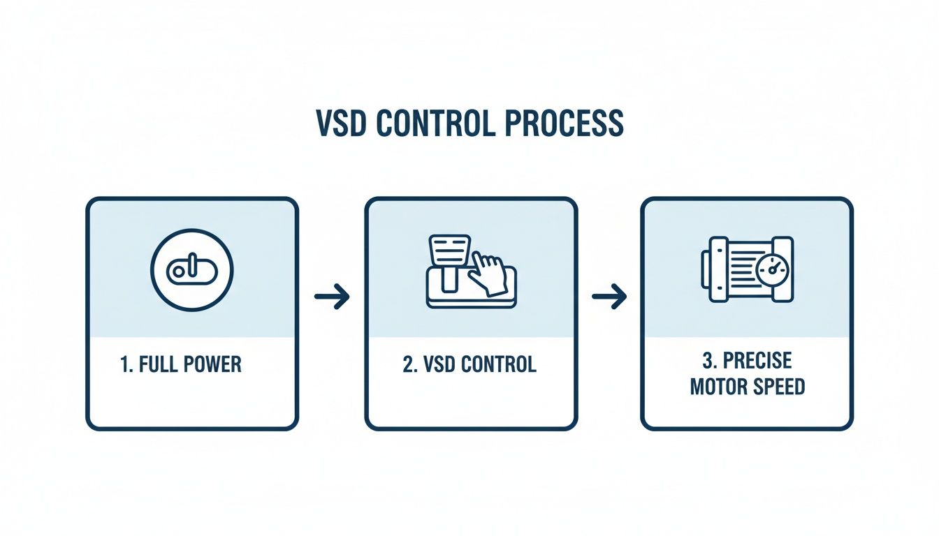
Variable Frequency Drive (VFD)
Controls the motor’s speed by adjusting the electrical frequency.
The Accelerator/Brake Pedal. It gives you precise control over how fast or slow the car (motor) is going.
Each of these components works together within the bucket to ensure a motor runs not just effectively, but safely. You’ve got the starter to get things moving, the overload relay to prevent burnout, and the breaker for catastrophic failure. For a deeper dive into how these protective devices work, we have a great guide on the fundamentals of motor protection.
More Than Just On/Off: Advanced Components
Modern MCCs aren't limited to simple start/stop functions. It's common to find buckets equipped with much more sophisticated technology.
A Variable Frequency Drive (VFD), for example, is a popular addition. Instead of just turning a motor on, a VFD gives you granular control over its speed. This is incredibly useful for applications like pumps and fans, where you can fine-tune performance to save a tremendous amount of energy and improve your process.
MCC vs Switchboard vs Panelboard
Walk onto any large commercial or industrial site, and you'll find an array of electrical gear. Three pieces that often get mixed up are the Motor Control Center (MCC), the switchboard, and the panelboard. While they all manage electricity, they have fundamentally different jobs.
Getting it wrong isn't just a technical mix-up; it can lead to major design flaws, safety risks, and a system that just doesn't work for its intended purpose.
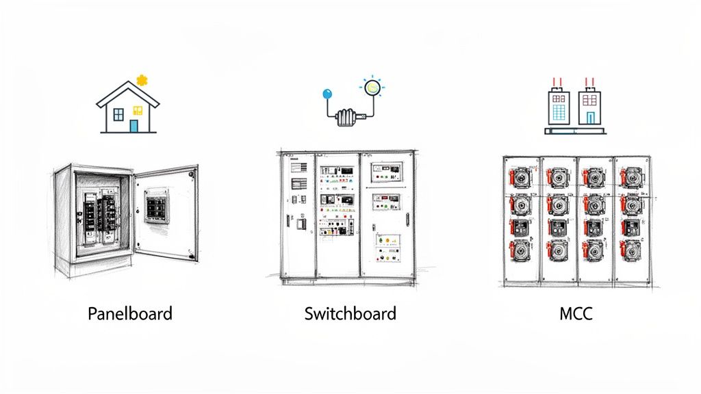
Think of a panelboard as the breaker box in your house. It’s the last stop for power, breaking it down into small, manageable circuits for things like lights, wall outlets, and small appliances. They're typically mounted on a wall and provide simple, direct overcurrent protection.
A switchboard is a step up the ladder. It’s the main distribution hub for a facility, taking the big power feed from the utility and splitting it into larger circuits. These circuits might feed an entire floor, a massive HVAC unit, or a series of downstream panelboards. Its job is bulk power distribution, not fine-tuned control.
The MCC: The Industrial Specialist
This is where the Motor Control Center comes in. The MCC is a specialist, purpose-built with one core mission: to centralize the control and protection of electric motors.
This isn't just about turning motors on and off. An MCC is a sophisticated assembly of combination starters, VFDs, and soft starters, all housed in modular, pull-out "buckets." This design is the heart of what makes an MCC so essential in tough environments like factories, refineries, and processing plants where dozens—or hundreds—of motors need to work together flawlessly.
A key takeaway is that an MCC's design prioritizes motor control, modularity for maintenance, and integration with automation systems, setting it apart from general power distribution equipment. While a switchboard is about routing power, an MCC is about controlling what that power does.
For a deeper dive into how MCCs stack up against other heavy-duty equipment, this detailed breakdown comparing a motor control center vs switchgear provides some great context.
To really nail down the differences, let's put them side-by-side.
Comparison of MCCs, Switchboards, and Panelboards
This table breaks down the core distinctions at a glance, making it easy to see where each piece of equipment fits.
Attribute
Motor Control Center (MCC)
Switchboard
Panelboard
Primary Function
Centralized motor starting, control, and protection.
Main power distribution for a building or large area.
Final distribution to smaller branch circuits (e.g., lights, outlets).
Modular, with withdrawable buckets for each motor.
Free-standing floor-mounted enclosure.
Typically smaller, wall-mounted cabinet.
Typical Application
Industrial plants, factories, water treatment facilities.
Commercial buildings, data centers, large institutions.
Homes, offices, small commercial spaces.
Flexibility
High; easily add or modify motor control units.
Moderate; requires significant work to modify.
Low; fixed number of circuit positions.
Ultimately, choosing between an MCC, switchboard, or panelboard comes down to the application. If you're managing a fleet of motors in an industrial process, the MCC is your tool. If you're distributing power across a commercial building, you need a switchboard. And for the final circuits, a panelboard gets the job done.
Decoding Key Safety and Design Standards
When you're dealing with industrial power, safety isn't just a suggestion—it's everything. The standards that govern MCC design are the very foundation of a reliable and safe system. They’re what stand between a smooth-running operation and a catastrophic failure like an arc flash.
For anyone working in North America, the conversation starts and ends with UL 845. This is the specific Underwriters Laboratories standard for Motor Control Centers. Think of it as the ultimate rulebook for how an MCC must be built, tested, and rated to perform under pressure. When you see a UL 845 mark, it means an independent body has verified that the MCC meets incredibly strict requirements for its wiring, busbar bracing, overall structure, and—most importantly—its ability to handle a short-circuit event without falling apart.
An MCC without a proper UL listing isn't just a compliance headache; it's a massive safety liability. That UL 845 certification is your third-party guarantee that the gear is built to a recognized safety benchmark, protecting both your people and your facility.
Matching Enclosures to the Environment
It’s not just what’s on the inside that counts. The physical cabinet, or enclosure, has to be tough enough for the world it lives in. This is where NEMA (National Electrical Manufacturers Association) ratings come into play, defining how well an enclosure protects against things like dust, water, and corrosion.
Picking the right one is a make-or-break decision for the MCC's lifespan:
NEMA 1: This is your standard indoor-use enclosure. It’s perfect for a clean, dry electrical room, mainly designed to keep people from accidentally touching live parts.
NEMA 12: Step it up for more typical industrial indoor spots. This rating adds protection against dripping liquids (non-corrosive), falling dirt, and circulating dust.
NEMA 4X: This is the heavy-hitter. Built to be watertight and corrosion-resistant, it's the go-to choice for washdown areas in a food processing plant or for outdoor installations near the coast where salt spray is a concern.
It’s also crucial to understand the nuances of certifications. For instance, knowing the difference between a product being UL Listed vs. UL Recognized is a big deal for system integrators, as it impacts how a component can be legally and safely integrated into a larger certified assembly.
A Global Perspective on MCC Standards
While UL and NEMA are the law of the land in North America, the rest of the world often looks to IEC (International Electrotechnical Commission) standards. The main equivalent to UL 845 is IEC 61439, which sets the rules for low-voltage switchgear and controlgear assemblies globally.
Even though the design philosophies and testing methods have their differences, both UL and IEC standards are chasing the same goal: ensuring the equipment is safe, reliable, and performs as expected. For companies with a global footprint, being fluent in both languages is essential to deliver compliant systems no matter the market.
Where Motor Control Centers Really Shine
Enough with the theory and diagrams. Let's talk about where the rubber meets the road. Motor Control Centers are the absolute workhorses of modern industry, the central nervous system that keeps the lights on and the products moving in some of the toughest environments you can imagine.
Once you see them in action, their value just clicks.
For anyone specifying or building systems—OEMs, packagers, integrators—getting a grip on these applications is everything. It’s how you move the conversation from a list of parts to the real-world, bottom-line benefits your clients actually care about.
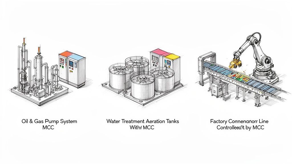
Oil and Gas Operations
Out on a rig or in a sprawling refinery, "downtime" is a four-letter word that costs millions. Here, reliability isn't just a feature; it's the entire game. An MCC is the heart of the operation, controlling the massive pumps, compressors, and drilling gear that make it all happen.
That modular bucket design we talked about? This is where it's a lifesaver. When a motor starter fails, a tech can pull the bucket, slap in a spare, and get a critical process back online in minutes. No rewiring, no complex troubleshooting under pressure. Just swap and go.
Water and Wastewater Treatment
Think about your local water treatment plant. It's a non-stop, 24/7 operation. MCCs are running the show from start to finish—intake pumps, chemical dosing systems, giant aeration blowers, you name it.
By centralizing all this control in a clean, dry electrical room, you're protecting all the sensitive VFDs and PLCs from the wet, corrosive environment of the plant floor. It’s a simple concept, but it's what ensures that essential public services run without a single hiccup.
The big takeaway is this: in any process-heavy industry, the MCC doesn't just send power to motors. It orchestrates the entire physical workflow. This centralization and modularity are why over 70% of motors above 10 hp in large facilities are fed from MCC lineups.
Advanced Manufacturing and Automation
Step inside a modern factory, and the MCC is the command center for the whole production line. It's the silent conductor making sure conveyors, robotic arms, mixers, and packaging machines all work in perfect harmony.
This is where intelligent MCCs really come into their own. They talk directly to the plant's main automation system, giving operators real-time performance data and even flagging potential issues before they cause a breakdown. This is the kind of control you need to hit the efficiency and uptime numbers that keep you competitive.
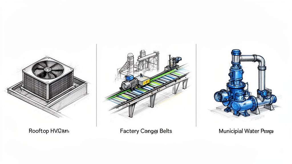
We see this same need for precise control in all sorts of settings, like in the specialized role of motor control centers in HVAC applications. And that simple bucket concept? It lets plants stock a handful of common spares, which can slash maintenance inventory costs to the bone.
How to Specify an MCC for Your Project
Specifying a Motor Control Center is a lot more than just checking boxes on a form. You’re really designing the nerve center for your entire operation. Nail the specs, and you get a safe, reliable system that just works. Get them wrong, and you're in for a world of operational headaches and costly fixes down the road.
The whole process kicks off with a deep dive into your electrical and mechanical needs. Before anything else, you have to get a handle on your total motor loads. That means creating a detailed motor list—every single one—with its horsepower (HP), full-load amps (FLA), and voltage. This list is the absolute foundation for sizing your main busbars and every individual circuit correctly.
Next up is the short-circuit current rating, or SCCR. This isn't a ballpark figure; it’s a critical safety calculation. The SCCR of your MCC absolutely must be higher than the available fault current at the spot where it's installed. An underrated MCC is a ticking time bomb that can fail catastrophically during a short circuit.
Key Specification Details to Consider
Once you’ve got the heavy-hitting electrical parameters sorted out, you can zoom in on the specific components and features your application actually needs. It's not enough to just say, "I need a starter." You have to think about the job each motor is doing.
Here’s a quick checklist to guide your thinking:
Component Type: Does that conveyor motor need a simple across-the-line starter, or would a soft starter be better to reduce wear and tear? What about that pump—does it need the precise speed control only a VFD can offer?
Enclosure Rating: Think about where this MCC will live. A clean, dry electrical room is fine with a NEMA 1 enclosure. But if it’s going in a washdown area in a food and beverage plant, you’ll need the protection of a NEMA 4X.
Intelligence Level: Are you okay with simple local start/stop buttons? Or do you need an intelligent MCC where all the components are networked, feeding data back to a central PLC for advanced control and diagnostics?
My best advice? Get an experienced system integrator or a UL 508A certified panel shop involved from the very beginning. Their expertise is pure gold when you're navigating complex design choices and trying to stay on the right side of the code.
Bringing in an expert early is a game-changer. They can look over your plans, spot potential problems you might have missed, and recommend solutions that are both reliable and cost-effective. They act as the perfect translator between your big-picture operational goals and the nitty-gritty technical details, ensuring the final MCC is a perfect fit, built safely, and made to last.
Common Questions About Motor Control Centers
Even after you get the basics down, you'll find that a whole new set of questions pop up when you're actually in the field working with Motor Control Centers. Let's tackle a few of the most common ones we hear from engineers and technicians to help connect the dots between the textbook and the job site.
What Is the Main Advantage of a Withdrawable Bucket?
The biggest win with a withdrawable MCC bucket is the massive improvement it offers for both safety and maintenance speed. Plain and simple.
Think about it: a qualified technician can completely de-energize, disconnect, and physically pull an individual motor control unit right out of the structure. And the best part? They can do it without having to shut down the entire MCC.
This is basically "hot-swapping" for motor controls. A bad unit can be swapped for a spare in a matter of minutes, which slashes expensive downtime. It also makes for a much safer repair job, since the complex work can be done on a bench, miles away from any live, high-voltage bus bars.
What Makes an MCC Intelligent?
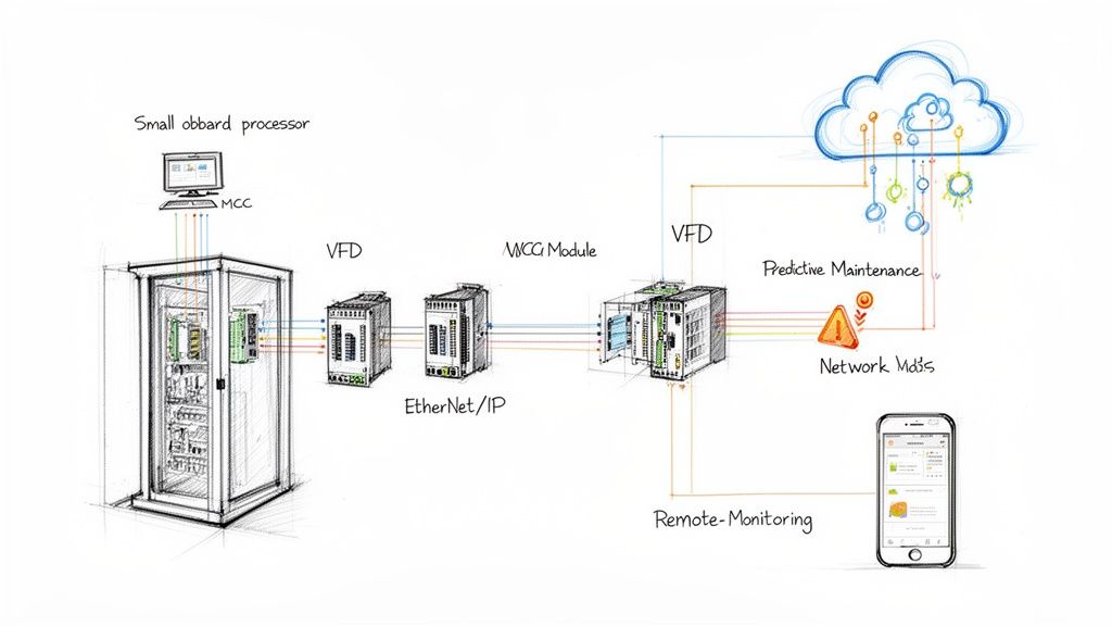
An "intelligent" MCC, or iMCC, is one that has modern communication and diagnostic tech baked right into its components. Instead of just handling simple start/stop commands, the units inside an iMCC are packed with networked devices—think overload relays, VFDs, and soft starters that are all chatting over an industrial network.
This setup opens up a world of possibilities. You get remote monitoring, real-time diagnostics, and even predictive maintenance data streamed directly to a central PLC or SCADA system. The payoff comes from faster troubleshooting, a huge drop in unplanned downtime, and detailed energy monitoring that helps you find new ways to improve efficiency.
At its heart, an intelligent MCC turns what was once just a "dumb" electrical cabinet into a goldmine of operational data. It gives plant managers a level of insight into the health and performance of their motors that was unheard of just a few years ago.
How Is the Required SCCR Determined?
Figuring out the required Short-Circuit Current Rating (SCCR) for an MCC isn't guesswork—it's a critical safety calculation. The SCCR is determined by the available fault current at the exact spot where the MCC will be installed.
This has to be calculated by a qualified electrical engineer as part of a formal, system-wide fault current study. No exceptions.
The rule is simple: the MCC's SCCR must be equal to or greater than the maximum potential fault current it could ever face. If you specify an MCC with a rating that's too low, you're creating a serious safety hazard and a direct violation of the National Electrical Code (NEC). An undersized MCC can fail catastrophically during a short-circuit, with devastating consequences.
At E & I Sales, we live and breathe this stuff. We specialize in designing and building custom, UL-listed control panels and MCCs that are a perfect fit for your project's unique demands. From the first spec sheet to the final commissioning, our team has the expertise to make sure your system is safe, reliable, and built for the long haul. Learn how our system integration services can get your next project off the ground and running smoothly.
Think of a VSD as the brains behind your motor's brawn. Instead of a basic on/off switch that slams equipment into action at full throttle, a VSD is more like a sophisticated dimmer switch or a gas pedal. It gives you the power to tell a motor exactly how fast to run and with how much force. This fine-tuned control is the secret to unlocking massive gains in efficiency and equipment longevity.
Understanding Variable Speed Drives
At its core, a VSD manages the power flowing into an electric motor to precisely regulate its rotational speed. The reality is, most industrial applications—pumps, fans, conveyors, you name it—don't need to run at 100% capacity all the time. Running them full-out when it isn't necessary is like flooring the accelerator in your car just to ride the brake. It's incredibly wasteful and puts a ton of unnecessary strain on the entire system.
A VSD neatly solves this problem by adjusting the electrical frequency and voltage supplied to the motor. This allows the motor to ramp up smoothly, run at the exact speed the job requires, and then gently ramp back down. It turns a simple, fixed-speed motor into a smart, adaptable, and highly efficient machine.
The Power of Precise Control
Picture a municipal water pump system. Without a VSD, the pumps would constantly cycle on and off with jarring force to maintain pressure, causing huge electrical surges and mechanical shockwaves through the pipes and valves. It’s brutal on the equipment.
Now, add a VSD. The pumps can run continuously at a much lower, more consistent speed, perfectly matching the real-time water demand. No more violent stops and starts.
This level of control delivers some serious advantages:
Energy Efficiency: This is the big one. By running motors only as fast as they need to, VSDs can slash electricity consumption. For common pump and fan applications, just a 20% speed reduction can lead to energy savings of nearly 50%.
Reduced Mechanical Stress: A VSD gives you a "soft start," eliminating the violent jolt of an across-the-line start. This gradual acceleration is much easier on belts, gears, and couplings, which means they last longer and fail less often.
Improved Process Management: VSDs let operators dial in their processes with incredible accuracy. The result is better product quality, less wasted material, and far more consistent output day in and day out.
A VSD bridges the gap between raw power and intelligent application. It ensures that a motor uses only the energy it needs, for as long as it's needed, transforming a brute-force tool into a precise instrument of control.
To put it simply, a VSD gives you the control you need to run a smarter, more efficient operation. Here's a quick breakdown of what they do and why it matters.
VSD At a Glance: Core Functions and Benefits
Core Function
Primary Benefit
Speed & Torque Regulation
Matches motor output directly to process demand.
Soft Starting/Stopping
Eliminates electrical inrush and mechanical shock.
Variable Frequency Control
Unlocks significant energy savings, especially in pump and fan systems.
Process Optimization
Enables precise adjustments for better quality and consistency.
Ultimately, integrating a VSD is about more than just saving a few dollars on your utility bill; it's about extending the life of your critical machinery and gaining a whole new level of control over your entire process.
How VSDs Actually Control a Motor
So, how does a VSD pull this off? The gas pedal analogy is great for the what, but the how is where the real engineering magic lies. To really get it, you have to look under the hood at the most common type of drive, the Variable Frequency Drive (VFD).
Think of a VFD as a sophisticated power converter. Its one job is to take the raw, fixed utility power coming into your facility and completely reshape it into a custom-made power signal that gives the motor precise instructions. This all happens in three quick stages.
Stage 1: The Rectifier
First things first, the drive has to deal with the incoming alternating current (AC) power from the grid. This power is a sine wave, constantly oscillating, which isn't a stable foundation for building a new, variable signal. The drive needs a clean slate.
That’s the job of the rectifier. It takes that incoming AC and converts it to direct current (DC). It does this using a set of diodes that act like one-way gates for electricity, forcing the oscillating current to flow in a single direction. The result is a pulsating DC voltage.
This step is critical. Without converting to DC first, the drive would be stuck with the grid's fixed frequency.
Stage 2: The DC Bus
That pulsating DC from the rectifier isn't quite ready for primetime—it still has ripples from the original AC waveform. The next component, the DC Bus (or DC link), cleans up the signal.
The DC Bus uses large capacitors, which essentially act as small, fast-charging batteries. They soak up the peaks of the pulsating DC and fill in the valleys, smoothing everything out into a stable, high-voltage DC supply.
The result is a stable, high-voltage DC supply. This clean DC power is now ready to be shaped and molded by the final, most critical stage of the process, allowing for ultimate control.
This intermediate step is what makes VFDs so flexible. By creating its own DC power source, the drive completely decouples the motor from the grid, giving it total freedom to build a brand-new AC signal from scratch.
Stage 3: The Inverter
This is where the real control happens. The inverter takes that clean, stable DC voltage from the bus and uses it to construct a new, synthetic AC power signal to send to the motor.
It accomplishes this with a series of incredibly fast electronic switches called Insulated-Gate Bipolar Transistors (IGBTs). These IGBTs chop up the DC voltage into a series of precisely timed pulses, a technique known as Pulse Width Modulation (PWM).
By controlling the width and frequency of these pulses, the inverter can perfectly simulate an AC sine wave at any voltage and frequency it needs.
To run the motor slower, the inverter creates a lower-frequency waveform.
To run it faster, it simply generates a higher frequency.
This PWM output is what gives the VFD its amazing precision, allowing motor speed to be dialed in perfectly for the application. To see how these components work together in more detail, you can explore some variable frequency drive basics.
The Business Case for Using Variable Speed Drives
Sure, the tech behind variable speed drives is interesting, but for any plant manager or CFO, the real question is much simpler: what’s the ROI? When you look past the spec sheets, VSDs make a powerful business case built on real-world financial gains, stabler operations, and better product quality. The benefits ripple out far beyond simple motor control, touching the entire lifecycle of your equipment.
The benefit everyone talks about first is the dramatic drop in energy consumption. Electric motors are the workhorses of industry, but they’re also responsible for a huge slice of industrial electricity bills. Many of these motors, especially those on pumps and fans, operate under a set of rules known as the Affinity Laws.
Unlocking Exponential Energy Savings
The Affinity Laws lay out the relationship between the speed of a centrifugal pump or fan and the power it draws. The key takeaway is that this relationship isn't linear—it's exponential. This means even a tiny reduction in motor speed can trigger a massive drop in energy use.
The Power of the Cube: According to the Affinity Laws, the power a pump or fan needs is proportional to the cube of its speed. This is where the incredible opportunity for savings comes from.
Let's look at a practical example:
Running a fan at 100% speed takes 100% of its design power. No surprise there.
But reduce that speed by just 20% (down to 80%), and the power consumption plummets to roughly 51%.
Slow it all the way down to 50% speed, and it sips power at a mere 12.5% of the original demand.
This powerful principle is precisely why VSDs are a game-changer for any application with variable demand. With around 300 million motors spinning away globally, a drive's ability to cut speed by just 20% can slash energy use by nearly 50% in common pump and fan scenarios. For a closer look at the math, check out our guide on calculating VFD energy savings.
This is one of the most effective ways to lower the energy footprint of industrial motor fleets worldwide. You can see how big the opportunity is by looking at the growth of the global variable speed drive market.
Extending Equipment Lifespan Through Soft Starting
Beyond the savings on your utility bill, VSDs act as a kind of mechanical insurance policy for your equipment. A motor started "across-the-line" (without a drive) gets hit with an instantaneous jolt of electricity, forcing it to lurch from zero to full speed in a split second. This is incredibly violent for the entire mechanical system.
That initial electrical inrush can be 600% or more of the motor's normal running current, and the mechanical shock is just as bad. It's like taking a sledgehammer to your machinery every single time you turn it on. All that stress leads to premature wear on critical components.
A VSD changes this completely by giving the motor a "soft start." It gently ramps up the voltage and frequency, allowing the motor to accelerate smoothly.
The benefits of a VSD-driven soft start are immediate:
Reduced Stress on Couplings: It prevents the sudden, jarring torque that damages or knocks couplings out of alignment.
Longer Bearing Life: It gets rid of the shock loading that is a primary cause of bearing failure in motors and the equipment they drive.
Less Wear on Belts and Gears: A smooth startup stops belts from slipping and eases the strain on gearbox components.
By taking that mechanical shock out of the equation, a VSD can dramatically extend the life of your motors, pumps, fans, and conveyors. That means fewer breakdowns and lower maintenance costs over the long haul.
Gaining Unprecedented Process Control
Finally, the incredible precision a VSD offers translates directly into better product quality and more consistent operations. In countless industrial processes, "full speed" isn't the optimal speed. Being able to fine-tune a motor's output gives you a level of accuracy that’s simply impossible with a basic on/off switch.
Think about a bottling line conveyor. If it runs too fast, bottles tip over, causing spills, cleanup delays, and wasted product. Too slow, and it creates a bottleneck that gums up the whole production line.
With a VSD, operators can dial in the exact speed to perfectly match the filler's output, creating a smooth, uninterrupted flow. This same idea applies everywhere, from managing pump pressure in a chemical mixing tank to controlling fan speed in a drying oven. This level of control cuts down on waste, improves consistency, and ultimately, boosts your bottom line.
Choosing the Right Motor Control Solution
Sure, a variable speed drive can do amazing things, but that doesn't mean every motor in your plant needs one. It's a classic engineering trade-off: balancing performance, complexity, and of course, cost. Over-engineering a simple application with a full-blown VSD is just as wasteful as letting a high-demand process limp along without one.
The real key is matching the technology to the job at hand. For the vast majority of industrial motors, the choice boils down to three common methods: the simple Across-the-Line Starter, the more refined Soft Starter, and the powerhouse Variable Speed Drive. Knowing where each one shines is the first step to making a smart, cost-effective decision for your operation.
The Three Tiers of Motor Control
Let's break down how these solutions stack up. Think of it like choosing a vehicle for a job. You wouldn't use a Formula 1 car for a quick trip to the hardware store, and you definitely wouldn't enter a delivery van in the Monaco Grand Prix. It’s the same logic with motor controls.
1. Across-the-Line (ATL) Starters This is the most straightforward option out there—basically, a heavy-duty on/off switch. When you hit "start," it connects the motor directly to the full line voltage. It's cheap, tough, and dead simple for applications where the motor just needs to run at one constant speed and the mechanical shock of a sudden, hard start isn't a dealbreaker.
2. Soft Starters A soft starter is a big step up, designed to solve one specific problem: the brutal mechanical and electrical jolt of an ATL start. It works by gradually ramping up the voltage to the motor, allowing it to accelerate smoothly and under control. Once the motor hits full speed, the soft starter is usually bypassed, letting the motor run directly off the line. It's the perfect middle ground for reducing stress on equipment like pumps or conveyors where you don't need to adjust the speed once it's running.
3. Variable Speed Drives (VSDs) The VSD is the most advanced of the bunch. Just like a soft starter, it delivers a smooth start, but that's where the comparison ends. A VSD gives you continuous, precise control over the motor's speed throughout its entire operation, not just at startup. This is the go-to solution for applications with changing loads, like pumps and fans, where matching motor speed to real-time demand can unlock massive energy savings and give you unparalleled process control.
To make this even clearer, let's put these three side-by-side.
Comparison: VSD vs. Soft Starter vs. Across-the-Line Starter
Choosing the right motor starter is a critical decision. Each type offers a different level of control, cost, and complexity, tailored to specific operational needs. This table breaks down the core differences to help you see which one fits your application.
Feature
Across-the-Line Starter
Soft Starter
Variable Speed Drive (VSD)
Primary Function
Basic on/off control
Smooth motor acceleration/deceleration
Continuous speed and torque control
Speed Control
None (runs at fixed speed)
None during operation (only at start/stop)
Full range, continuous speed control
Startup Current
Very high (600-800% of full load)
Reduced (150-400% of full load)
Limited and controlled (typically <150%)
Mechanical Stress
High (sudden torque)
Low (gradual ramp-up)
Very low (fully controlled)
Energy Savings
None
Minimal (only at startup)
Significant (especially on variable-torque loads)
Best For
Simple, constant-speed applications like mixers or saws where startup shock is acceptable.
Applications needing to reduce mechanical stress on startup, like conveyor belts or centrifugal pumps that run at a single speed.
Applications with variable loads or requiring precise process control, like HVAC fans, pumps, and extruders.
Complexity & Cost
Low
Medium
High
Ultimately, the best choice depends entirely on the job the motor is doing. For a simple "run-or-don't-run" task, an ATL starter is perfectly fine. But when you need to protect your equipment or manage your energy bill, you need to look at soft starters and VSDs.
When Is a Soft Starter Enough?
This is a common fork in the road for many engineers: do I really need the VSD, or can I get by with a soft starter? While both give you a gentle startup, their core purpose is completely different. A soft starter is a one-trick pony—a very good one—but its job is over the second the motor gets up to speed.
You should lean towards a soft starter when:
Your main goal is to reduce mechanical stress on startup and shutdown.
The motor only needs to run at a constant, full speed during operation.
You need to limit the massive inrush current from an ATL start to stop lights from dimming or breakers from tripping.
The application simply does not require variable speed for process control.
A classic example is a long, heavily loaded conveyor belt. Slamming it with full power would jerk the belt, potentially spilling product or damaging the gearbox. A soft starter ensures a smooth, gentle ramp-up to its single operating speed, protecting the equipment without the extra cost and setup of a VSD.
When Do You Need a Full VSD?
The decision to specify a VSD really boils down to one question: do you need continuous speed control? If you can make your process better, more efficient, or more precise by adjusting the motor's speed while it's running, then a VSD is the right tool. It’s not just a starter; it’s a process optimization machine.
A soft starter is like a ramp onto the highway—it gets you up to speed safely. A VSD, on the other hand, is the entire cruise control system, constantly adjusting your speed to match traffic for peak efficiency and performance.
You absolutely need a VSD when:
The application has variable loads, like HVAC fans or centrifugal pumps.
Energy savings are a major priority, especially where you can leverage the Affinity Laws.
Your process demands precise speed regulation to maintain product quality.
You need to run the motor at several distinct speeds for different parts of a machine cycle.
Think about the HVAC system in a large building. You don't need the fans blasting at 100% on a mild spring day. A VSD lets the system slow those fans way down, keeping everyone comfortable while slashing the electricity bill. A soft starter just can’t do that—it lacks the ongoing speed adjustment needed to capture those savings.
By clearly defining what your motor needs to do from start to finish, you can confidently choose the control solution that gives you the right performance at the right price.
Just picking out the right variable speed drive is only half the battle. A truly successful project comes down to what happens next—the integration. This is where the drive, the motor, and your actual application have to learn to work together, and it's where careful planning pays off big time.
Getting this part wrong is a recipe for disaster. We're talking premature motor failures, weird electrical noise messing with other equipment, and the kind of unexpected downtime that ruins a production schedule. Let's walk through the essential checklist to make sure your VSD integration is smooth, reliable, and delivers from day one.
Ensuring Motor and Drive Compatibility
First things first: is your motor actually ready for a VSD? A drive doesn't spit out the same clean, perfect AC power that comes from the utility. Instead, it uses a technique called Pulse Width Modulation (PWM) to create a simulated AC wave, and that high-frequency output can be brutal on standard-issue motors.
Hooking up a VSD to a motor that wasn't built for it can cause a world of hurt:
Insulation Breakdown: Those rapid-fire voltage spikes from the drive can eat away at the motor's winding insulation, leading to shorts and, eventually, a dead motor.
Overheating: The harmonics created by the VSD generate extra heat inside the motor, cooking it from the inside out and dramatically shortening its life.
Bearing Damage: Stray voltages can build up on the motor shaft, creating tiny electrical arcs that pit the bearing races. This "electrical discharge machining" (EDM) is a notorious and premature bearing killer.
This is exactly why you should always pair a VSD with an "inverter-duty" rated motor. These aren't your average motors. They’re built tough, with beefed-up insulation, better cooling designs, and often include shaft grounding rings to handle the unique stresses a drive throws at them.
Managing Electrical Noise and Harmonics
While VSDs are incredible tools, they're also what's known as "non-linear loads." This means they draw power from the grid in quick, sharp pulses instead of a smooth, continuous wave. The side effect of this process is electrical "noise" that gets pushed back into your facility's power system. We call this harmonic distortion.
If you let harmonics run wild, they can cause some serious chaos for other sensitive electronics on the same network. You might see flickering lights, but you could also face much bigger problems, like overheating transformers or circuit breakers that trip for no apparent reason. It’s a major power quality issue that can disrupt your entire operation.
Managing harmonics isn't just a good idea—it's often a requirement. Many utilities have strict rules about how much harmonic distortion you can feed back into their grid.
Thankfully, this is a solvable problem. There are proven solutions designed to clean up that electrical signal and keep your system from interfering with itself or its neighbors. You can learn more by exploring the different types of harmonic filters for VFDs and how they work.
Selecting the Right Enclosure and Cooling
A VSD is a powerful piece of electronics, and just like your computer, it needs protection from the environment and has to stay cool to work properly. Heat is the ultimate enemy of electronics, and a drive generates a fair bit of it—typically losing about 2-3% of the power it handles as waste heat.
Enclosure Ratings are your first line of defense. A simple NEMA 1 enclosure might be fine in a clean, dry electrical room. But that same enclosure would get destroyed in a food processing washdown area or a dusty quarry. You have to match the enclosure to the job (like a NEMA 4X for corrosive areas or NEMA 12 for dusty indoor spots) to keep your drive safe.
Proper cooling and ventilation are equally vital. That enclosure needs a way to get rid of the heat the drive produces. This can be as simple as:
Giving It Space: Always follow the manufacturer's specs for clearance around the drive to allow for natural airflow.
Using Fans: Many panels integrate fans and filters to pull in cool ambient air and push out the hot air.
Adding Air Conditioning: For sealed panels in really hot or dirty places, a dedicated A/C unit is the only way to go.
Skimping on thermal management is one of the fastest ways to get nuisance faults and a drastically shorter lifespan for your VSD. A solid enclosure and cooling plan isn't a luxury; it's a core part of any reliable installation.
Where You'll Find VSDs in the Real World
Variable speed drives are the unsung heroes of the modern world, quietly working behind the scenes in countless places you might not expect. They aren't just for specialized, high-tech factories. Their incredible versatility has made them essential to our infrastructure, manufacturing plants, and even the office buildings we work in.
Once you know what you’re looking for, you’ll start to see their impact everywhere. This isn't a niche trend; it's a massive shift in how industries operate. Projections from Global Market Insights suggest that annual VFD installations will blow past 30 million units worldwide. That’s a huge indicator of the value they deliver. Big players in automotive, oil & gas, and food and beverage are all jumping on board to get a handle on their energy costs and production quality.
From keeping a massive industrial plant running smoothly to managing the climate in a skyscraper, these drives are making our world more efficient.
Optimizing Commercial HVAC Systems
One of the most common places you’ll find a VSD is tucked away with a building's heating, ventilation, and air conditioning (HVAC) system. The huge fans pushing conditioned air through ducts and the pumps circulating hot or chilled water simply don't need to run at 100% speed all the time. That would be a colossal waste of energy.
Instead, a VSD lets the building's automation system fine-tune fan and pump speeds based on what's actually happening—things like the outdoor temperature, how many people are in the building, and the time of day. On a cool spring afternoon, the VSD will automatically slow the fans down, saving a fortune on electricity while keeping everyone comfortable. This kind of smart control is the secret sauce behind today’s energy-efficient buildings.
Precision in Manufacturing and Production
In the world of manufacturing, control is king. VSDs are absolutely critical for dialing in the speed of equipment like conveyor belts, industrial mixers, and extruders, ensuring every product is made to spec and the whole line runs like a well-oiled machine.
Think about a bottling plant. Bottles cruise down a conveyor to get filled. Without a VSD, that conveyor is stuck at one speed, which is almost never the perfect speed for the filler. A mismatch leads to spills, jams, and a whole lot of wasted product and time.
With a VSD, operators can sync the conveyor's speed perfectly with the rest of the line. It sounds simple, but that one change slashes waste, cuts down on frustrating jams, and makes sure every bottle is handled just right.
You see this kind of advanced motor control in the automotive world, too. If you've ever wondered how hybrid cars actually work, you're seeing some of these same variable speed principles in action.
Ensuring Stability in Water Management
Our municipal water and wastewater systems depend on VSDs to keep pressure and flow steady across the entire network. In the old days, pumps would slam on and off to fill a water tower or keep pressure up in the pipes. This caused huge pressure surges and put incredible stress on the whole system.
Today, a VSD can run a pump continuously at the exact speed needed to match the community's water demand in real time.
In the middle of the night when demand is low, the VSD slows the pump way down.
As people wake up and demand spikes, the drive smoothly ramps up the pump’s speed to keep the pressure rock solid.
This doesn't just save an enormous amount of electricity; it also dramatically extends the life of expensive pumps, motors, and pipes by getting rid of those violent start-stop cycles.
Common Questions We Hear About VSDs
When you're dealing with motor control, a few practical questions always seem to pop up. We get them all the time from engineers and plant managers trying to get their heads around variable speed drives, so let's clear up some of the most common ones.
Can I Slap a VSD on Any Old Motor?
Not really. While you can connect a drive to most standard AC motors, you shouldn't. For the system to last, you absolutely need an inverter-duty rated motor.
Why? Because these motors are built differently. They're designed to handle the unique electrical stress a VSD puts out. Trying to run a standard motor off a drive is a recipe for trouble down the road.
You'll start seeing problems like:
Overheating from the high-frequency electrical "noise" created by the drive.
Fried insulation caused by sharp voltage spikes from the VSD's output.
Destroyed bearings thanks to stray electrical currents finding their way to ground.
What's the Real Difference Between a VSD and a VFD?
This one trips a lot of people up, but it's pretty simple. Variable Speed Drive (VSD) is the big-picture, catch-all term for any device that can change a motor's speed.
A Variable Frequency Drive (VFD) is just one specific—and by far the most common—type of VSD. It works by changing the frequency of the power going to an AC motor.
Because VFDs are everywhere, you'll hear people use "VSD" and "VFD" like they mean the same thing. And in day-to-day conversation, that's usually fine. Just remember: all VFDs are VSDs, but not every VSD is a VFD.
Seriously, How Much Energy Can a VSD Save?
The savings depend entirely on the job the motor is doing. For equipment like pumps and fans—what we call centrifugal loads—the results are staggering. It all comes down to a set of rules called the Affinity Laws, which show that a tiny drop in speed leads to a massive drop in power consumption.
It sounds crazy, but it's true: slowing a fan down by just 20% can slash its energy use by almost 50%.
Even on constant torque loads like conveyors, the savings are still very real. The drive makes sure the motor only pulls the exact amount of power it needs to move the load, and not a single watt more.
At E & I Sales, our job is to design and build UL-listed control solutions that fit right into your plant. From picking the right motor to getting it commissioned, we have the expertise to make sure your VSD project delivers. See how we can help with your next project at https://eandisales.com.
Put simply, a motor's service factor is a multiplier that tells you how much extra load it can handle for short bursts. It's essentially a built-in safety margin. For example, a motor with a 1.15 service factor can operate at 15% above its rated horsepower without immediately frying itself.
Decoding Motor Service Factor: The Built-In Power Margin
Think of it like driving a car. You wouldn't drive with the pedal floored and the engine screaming in the redline all day. But to get up a steep hill or pass another vehicle, you might push it for a few moments. The car is built to handle that brief, intense demand.
A motor's service factor is that engineered redline. It's not "free" horsepower—it's a carefully calculated reserve capacity designed to handle the unpredictable, real-world challenges that inevitably pop up.
The Official Definition And Its Practical Meaning
The National Electrical Manufacturers Association (NEMA) gives us the formal definition. According to the NEMA MG 1 standard, the service factor (SF) is "a multiplier which, when applied to rated power, indicates a permissible power loading that may be carried under the conditions specified for the service factor.”
In plain English, this means a 10 horsepower (HP) motor with a 1.15 SF is thermally designed to safely deliver 11.5 HP when needed. That 1.15 value has become an unofficial standard for general-purpose industrial motors for a reason.
This built-in cushion is absolutely critical for a few key reasons:
Handling Unexpected Loads: It gives the motor the muscle to manage intermittent spikes in demand, like when a conveyor belt has to start moving under a particularly heavy load.
Voltage Fluctuations: It provides a buffer against the minor voltage sags common in industrial plants, which could otherwise cause the motor to struggle or overheat.
System Resiliency: It makes the whole operation more robust, preventing nuisance trips and production stoppages from brief, unusual operating conditions.
In essence, service factor provides a margin for error. It’s the difference between a system that runs smoothly despite minor hiccups and one that constantly trips offline, causing expensive downtime.
Getting a handle on this concept is about more than just numbers on a nameplate. It's about understanding how electrical power gets converted into the real-world mechanical work that gets the job done. For a closer look at that relationship, our guide on torque calculation for a motor is a great next step.
Properly applying service factor ensures you're designing and maintaining reliable, resilient industrial systems that perform exactly as you expect them to.
Finding and Reading the Service Factor on a Motor Nameplate
Think of a motor's nameplate as its birth certificate and resume rolled into one. It’s packed with every critical detail you need to know about what that motor can do, and learning to decipher it is a core skill for anyone in the field.
When you're looking for the service factor, you won't have to search too hard.
Most manufacturers make it pretty obvious. Just scan the nameplate for the abbreviations SF or S.F., or sometimes the full "Service Factor." It’s almost always a decimal, like 1.15 or 1.25, and you'll usually find it huddled up next to the other headliners like horsepower (HP), RPM, and voltage.
But just spotting the number is only half the battle. That little decimal doesn't mean much in isolation. To really understand what it's telling you, you have to see it as part of the bigger picture, especially in its relationship with the motor's horsepower and full-load amperage (FLA).
Putting The Numbers In Context
Here's the best way to think about it: the horsepower rating is the motor's day-in, day-out marathon pace. It's the load it was designed to handle continuously without breaking a sweat.
The service factor? That’s the motor’s sprint capability. It tells you exactly how much extra power you can pull from it for short bursts without causing immediate damage. These two numbers work as a team, defining the absolute peak power the motor can safely deliver under ideal conditions.
Take a look at this real-world example. On the nameplate below, the SF is clearly marked as 1.15. Notice where it’s located—right next to the 3 HP rating. That’s not a coincidence. Manufacturers put them side-by-side to emphasize their direct link.
Getting this connection right is absolutely crucial. It’s the key to sizing your equipment correctly and, just as importantly, setting up your protective devices to prevent a burnout.
How Using Service Factor Impacts Motor Lifespan
Pushing a motor into its service factor range might feel like getting a free power boost, but there's a steep price to pay: a shorter lifespan. There’s no such thing as free horsepower. The cost of tapping into that reserve margin is accelerated wear and tear, pure and simple.
The number one enemy of any electric motor is heat. Running continuously into the service factor generates a ton of it, and that heat directly attacks the motor's most vulnerable parts—the winding insulation and the bearings. When you push a motor past its rated horsepower, the current draw goes up, which in turn cooks the windings. This thermal stress is the single biggest reason motors fail before their time.
The 10-Degree Rule and Its Financial Impact
There's a well-known rule of thumb in motor maintenance called the "10-degree rule." It’s a harsh but accurate guideline: for every 10°C (18°F) you run a motor's windings above their rated temperature, you cut the insulation's life in half. It's an unforgiving penalty for running too hot.
Let's take a motor with a 1.15 service factor. When you operate it at that peak load, you're not just asking for 15% more power; you're generating a disproportionate amount of heat. According to guidance from both EASA and NEMA, this overload rapidly ages the insulation and bearings. While a 1.15 SF load increases the current by about 15%, the heat generated is a different story. Heat from resistance (known as I²R loss) scales with the square of the current, meaning the extra heat is actually closer to 32%. You can discover more insights about motor thermal limits on PlantEngineering.com.
This isn't just an abstract electrical principle; it has real, tangible financial consequences. An overheated motor leads directly to:
Brittle Insulation: Over time, the heat makes the insulation on the copper windings fragile and prone to cracking. This leads to electrical shorts and catastrophic failure.
Bearing Failure: That same excess heat breaks down the grease in the motor's bearings, causing more friction, seizing, and eventually, a total breakdown.
Unexpected Downtime: A motor that dies prematurely grinds production to a halt, leading to expensive delays and emergency repair bills.
Think of a motor's service factor as a temporary reserve for unexpected peaks, not a continuous operating point. Leaning on it all the time is a surefire way to drive up maintenance costs, shorten your equipment's life, and deal with unplanned shutdowns.
Getting this relationship right is critical for building a reliable system. It’s not just about picking the right motor, but also setting up the proper safeguards. That’s why we also recommend you read our detailed guide on the protection of motors.
Smart Applications for Sizing Motors and Setting Overloads
Knowing what a motor service factor is on paper is one thing, but the real magic happens when you apply it intelligently out in the field. Seasoned pros don't look at a service factor as free horsepower; they see it for what it is—a strategic buffer. It’s a crucial safety margin for dealing with the messy, unpredictable reality of industrial work.
This built-in capacity is the perfect tool for handling those temporary, intermittent peak demands that can bring a lesser system to its knees. Think of a positive-displacement pump that has to work a little harder to push through a slug of thick fluid, or a conveyor belt groaning to a start under a heavy, lopsided load. These are precisely the moments a 1.15 SF is designed to absorb, preventing a costly system shutdown.
This isn't a new concept. Service factor has always been a design and reliability margin meant to cover real-world uncertainties, like minor voltage sags or the simple fact that it's tough to predict the exact horsepower an application will need. For system integrators building complex motor control centers, specifying motors with a 1.15 SF on critical drives is a time-tested strategy to slash nuisance trips and keep the line running. For a great technical breakdown on how this NEMA-defined margin adds reliability, check out this piece on Electrical Engineering Portal.
Setting Overload Protection Correctly
One of the most critical jobs for service factor is in setting a motor's overload protection. This is where theory directly impacts equipment safety and operational uptime. If you set the overload relay too low, you're signing up for frustrating nuisance trips. But set it too high, and you're leaving your expensive motor completely exposed to burnout.
Thankfully, the National Electrical Code (NEC) gives us clear, direct guidance. According to NEC 430.32, for any motor with a service factor of 1.15 or greater, you can set the overload device at up to 125% of the motor's Full Load Amps (FLA) listed on the nameplate. This setting gives the motor breathing room to safely use its service factor margin for short periods without tripping out.
On the other hand, if you're working with a motor with a service factor of 1.0, the rule changes. The maximum overload setting is capped at 115% of the FLA. That tighter tolerance is there for a reason—the motor has no built-in thermal capacity to handle overloads.
The bottom line is simple: your motor's service factor directly dictates how you configure its primary defense mechanism. Getting this setting right is fundamental to protecting your investment.
This relationship between running in the service factor, heat, and motor life is a straight line. The more you lean on that SF, the more heat you generate, and heat is the number one enemy of a motor's insulation and bearings.
As you can see, consistently relying on the service factor generates excess heat, which is the fast track to premature motor failure.
A Practical Step-by-Step Example
Let's walk through a quick, real-world scenario to lock this in.
Check the Nameplate: You've got a 10 HP motor. The nameplate shows an FLA of 28 amps and an SF of 1.15.
Apply the NEC Rule: Since the SF is 1.15, we know we can go up to 125% of the FLA for our overload setting.
Do the Math:28 Amps (FLA) x 1.25 = 35 Amps.
Set the Overload Relay: You'll dial in your overload relay to trip if the current draws more than 35 amps for a sustained period.
This simple calculation gives you a system that's both tough and safe. Getting these protective devices configured correctly is a core skill in motor control. For those who want to go deeper, we have a complete guide on how to size a motor starter that unpacks all these components in much more detail.
When You Should Avoid Using the Service Factor
While a motor’s service factor gives you a nice little power margin, it’s a tool with strict limitations, not a get-out-of-jail-free card. Knowing when not to use it is just as important as knowing when you can. In certain environments, leaning on that built-in buffer isn't just a bad idea—it can be downright dangerous.
Think of the service factor as a thermal savings account. In some situations, external conditions have already spent that entire savings for you, leaving zero margin for error.
High Ambient Temperatures and High Altitudes
A motor's standard ratings, including its service factor, are based on a very specific set of ideal conditions: operating at or below 40°C (104°F) and at an altitude of no more than 1,000 meters (3,300 feet). The moment you step outside those boundaries, the motor's ability to keep itself cool starts to plummet.
High Temperatures: In a hot factory or outdoors in the summer sun, the motor is already struggling to shed its own heat. Pushing it into the service factor range generates even more heat, which can cook the winding insulation and lead to a catastrophic failure.
High Altitudes: The air gets thinner the higher you go. Thinner air means the cooling fan can't move as much heat away from the motor's body, making it run hotter even under a normal load.
In both of these scenarios, the environment itself effectively "uses up" the thermal cushion that the service factor is meant to provide. To operate safely, you have to derate the motor and treat its service factor as 1.0.
Hazardous and Explosive Environments
When you're dealing with a location classified as hazardous—think refineries, grain elevators, or chemical plants—any extra heat can become an ignition source for flammable dust or vapors. It’s no surprise, then, that motors built for these environments are held to a much higher safety standard.
In hazardous locations, the motor's surface temperature is a critical safety parameter. Operating in the service factor range raises this temperature, creating an unacceptable risk. For this reason, all hazardous-duty motors are rated with a 1.0 service factor and must never be operated above their nameplate horsepower.
When Using a Variable Frequency Drive (VFD)
Heads up: pairing a standard, general-purpose motor with a Variable Frequency Drive (VFD) almost always means you forfeit the service factor. A VFD controls the motor's speed by manipulating the power waveform, a process that inherently introduces extra heat into the motor windings. This heating effect is especially bad at low speeds when the motor's own cooling fan is barely spinning.
That added heat from the VFD eats up the motor's thermal reserve, making it totally unsafe to push the load beyond its nameplate rating. Unless you're using a specialized inverter-duty motor that is explicitly designed with a service factor for VFD operation, you must assume the SF is 1.0.
The table below summarizes the key conditions where you need to back off and treat the service factor as 1.0.
Service Factor Derating Guide
This table outlines common operating conditions that require derating a motor's service factor to 1.0 to ensure safe, reliable operation and prevent premature failure.
Operating Condition
Recommended Service Factor
Reason for Derating
Ambient Temp > 40°C (104°F)
1.0
Reduced cooling capacity prevents the motor from dissipating the extra heat of an overload.
Altitude > 1,000 m (3,300 ft)
1.0
Thinner air makes the cooling fan less effective, increasing operating temperature.
Hazardous/Explosive Locations
1.0
Prevents surface temperatures from exceeding safety limits and becoming an ignition source.
Used with a Standard VFD
1.0
The VFD introduces additional heat, consuming the motor's thermal margin.
Frequent Starting/Stopping
1.0
High inrush currents during startup generate significant heat, leaving no room for overload.
Remember, these are not just suggestions; they are critical guidelines for protecting your equipment, your facility, and your personnel. When in doubt, always derate to a service factor of 1.0.
Expert Guidance for Motor and Control Panel Design
Really getting a handle on motor service factor is a game-changer when you're designing systems that need to be both tough and cost-effective. It’s what lets you turn those abstract numbers on a nameplate into smart engineering calls, making sure your equipment can actually handle what the real world throws at it. This is how you nail the balance between performance and a long, reliable service life.
But you can't just stop at the motor. To apply these principles right, you have to look at the whole electrical system. The motor is just one piece of the puzzle—the control panel protecting it is just as crucial. This is where teaming up with an expert who gets the entire picture, from the motor spec all the way to the UL-listed control panel integration, really pays off.
Aligning Components for Optimal Performance
A single-source partner is your best bet for making sure your motor, overload protection, and system controls are all singing from the same song sheet. This kind of integrated approach helps you sidestep the usual traps, like mismatched parts or badly configured safety devices, which are a fast track to premature failures and expensive downtime.
By treating the motor and its controls as one unified system, you're optimizing the entire operation for safety, reliability, and peak performance right out of the gate. It's about preventing problems before they even have a chance to start.
This holistic way of thinking takes the guesswork out of the equation and guarantees every component is working together smoothly. For instance, an expert can pinpoint a motor with the perfect service factor for your specific load, then build a control panel with overload relays calibrated precisely to that motor’s unique FLA and SF ratings.
When you get down to it, this level of detailed engineering gives you a system that isn't just up to code—it's built to last. It’s about creating a dependable operational backbone that supports your production goals without cutting corners, making sure your investment is protected by smart, forward-thinking design.
Got Questions About Motor Service Factor?
Once you get the hang of motor service factor, you start running into those tricky real-world situations. It’s one thing to understand the theory, but it’s another to apply it when you’re standing in front of a control panel. Let’s clear up a few of the most common questions that pop up.
Can I Use a VFD to Squeeze More Horsepower Out of the Service Factor?
This is a big one, and the answer is a hard no. It's a common and frankly dangerous assumption. The moment you connect a standard motor to a Variable Frequency Drive (VFD), its service factor is automatically reduced to 1.0. You should never try to push the motor beyond its nameplate horsepower rating when using a VFD.
Why? It all comes down to heat. A VFD introduces extra heat into the motor windings, a problem that gets worse at lower speeds when the motor's own cooling fan isn't spinning fast enough to be effective. That extra heat eats up the very thermal safety margin the service factor was meant to provide. Unless you have a specific inverter-duty motor that is explicitly rated for VFD use with a service factor above 1.0, the rule is absolute: SF is 1.0.
Is a Motor with a 1.25 SF Just Flat-Out Better Than One with a 1.15 SF?
Not at all. "Better" is completely relative to the job at hand. A higher service factor like 1.25 definitely gives you a bigger cushion for short-term overloads, but it doesn't make the motor superior across the board.
For instance, you’ll often see a 1.25 SF on Open Drip-Proof (ODP) motors, where there's plenty of airflow to help with cooling. On the flip side, a heavy-duty, Totally Enclosed Fan-Cooled (TEFC) motor built for a gritty, tough environment might be designed with a more conservative 1.15 SF. The best motor is the one that's a perfect match for its load, environment, and duty cycle. A high SF is great for unpredictable loads, but a 1.0 SF motor sized perfectly for a steady, continuous load might even be the more efficient choice.
How Does Running in the Service Factor Range Affect My Warranty?
Running a motor in its service factor range (above its rated horsepower) won't automatically void your warranty. After all, the motor was designed with that capability for intermittent use.
But here’s the catch: consistently running in that SF range dramatically shortens the life of the motor's insulation and bearings, making a premature failure much more likely. If the motor burns out from overheating because it was running in its SF range plus dealing with other stressors like high ambient heat, a manufacturer could easily challenge or deny a warranty claim. They expect you to use the service factor as a safety net for occasional spikes, not as a permanent horsepower boost.
At E & I Sales, we know that peak performance comes from the whole system, not just one part. Our experts are here to help you select the right motor and design a custom, UL-listed control panel that delivers the protection, reliability, and longevity your operation demands. Learn more about our comprehensive motor and control solutions.
So, what exactly is an electrical Motor Control Center (MCC)?
Put simply, it’s the nerve center for all the electric motors in an industrial facility. Think of it as a single, centralized cabinet built to house, power, and protect a whole group of motors and their associated gear.
What an MCC Does, and Why You Need One
To really get what an MCC does, let's take a step back. Picture a sprawling factory floor from a few decades ago. Every pump, conveyor, and fan would have its own starter, disconnect switch, and overload protection bolted to a wall or column nearby.
This setup was a mess. It was a maintenance nightmare, a serious safety hazard, and a huge time sink for any technician trying to track down a problem.
The Motor Control Center was invented to fix all of that. It takes all those scattered components and organizes them into one purpose-built, engineered assembly. It’s like going from a chaotic neighborhood of single-family homes, each with its own separate utilities, to a modern high-rise with everything managed from a central, secure utility room. The operational payoff is massive.
The Three Pillars of an MCC
At its core, an MCC is all about improving three key things:
Safety: It neatly tucks away high-voltage components inside a grounded metal cabinet. With features like interlocking door handles, it drastically cuts down the risk of accidental contact and protects your team from dangerous arc flash events.
Efficiency: Instead of hunting down components across the plant, technicians can troubleshoot, service, and swap out motor controls from one spot. This means less downtime and lower labor costs. Simple as that.
Organization: An MCC brings a clean, logical layout to your motor circuits. This makes reading electrical schematics a breeze and simplifies any future expansions or system changes.
Now, it’s easy to confuse an MCC with other big electrical cabinets, but they serve very different roles. We’ve put together a guide that breaks down the specifics, and you can learn more about the comparison between a motor control center vs switchgear to see why an MCC is a specialized piece of equipment for motor management, not just general power distribution.
Ultimately, an MCC is more than just a box of parts; it’s a strategic investment in how you manage power. It’s a system designed from the ground up for reliability, safety, and the long-term health of any operation that runs on electric motors.
Exploring The Anatomy Of A Motor Control Center
Pop open the door of a Motor Control Center (MCC), and it might seem a bit overwhelming at first. But what looks like a complex maze of components is actually a brilliantly organized system. Forget any images of a chaotic web of wires; a modern MCC is built on a framework designed for safety, modularity, and easy access.
I like to think of it as an electrical command center. The entire structure consists of one or more vertical metal cabinets bolted together. The backbone of the whole setup is the common power bus—a set of heavy-duty copper or aluminum bars running horizontally through the sections. This bus is the superhighway for electricity, distributing high-amperage power to every single unit and getting rid of the need for miles of individual wiring to each motor.
This flowchart really nails the core principle: taking scattered, hard-to-manage motors and bringing them under one roof for streamlined control.
As you can see, centralizing everything in a single, accessible enclosure is a huge win for efficiency and makes maintenance worlds easier.
Inside The MCC Buckets
The true genius behind the MCC is found in its motor control units, or as everyone in the field calls them, "buckets." These are essentially removable drawers that plug right into that main power bus. Each bucket is a self-contained module, dedicated to controlling and protecting one specific motor out on the plant floor.
This plug-and-play design is a lifesaver for maintenance teams. When a component inside a bucket fails, a technician can de-energize it, pull the entire bucket out, and slot in a spare. Just like that, the motor is back online in minutes, not hours. The faulty unit gets taken back to the shop for repair on a workbench, safely away from any live equipment.
To help you get familiar with what you'll find inside, here's a quick rundown of the essential parts packed into a standard MCC bucket.
Key Components Inside Every MCC Bucket
Component
What It Does
Why It Matters
Motor Starter
An electrical contactor that opens or closes a circuit to start and stop the motor.
This is the primary on/off switch, directly controlling the motor's operation.
Overload Relay
Monitors the current flowing to the motor and trips if it detects a sustained overload.
Acts as a critical safety net, preventing the motor from overheating and burning out.
Circuit Breaker
Provides short-circuit and overcurrent protection for the entire bucket circuit.
Protects the wiring and components from catastrophic failure and serves as a local power disconnect.
These three components form the core of what's often called a "combination starter," providing the fundamental control and protection every motor needs.
By official definition, an MCC is an assembly of one or more enclosed vertical sections sharing a common power bus and principally containing motor control units. Low-voltage MCCs typically handle motors from 220V to 600V, while their medium-voltage counterparts can manage massive motors running up to 15 kV. You can find more of the formal definitions over on the Wikipedia page for Motor Control Centers.
Advanced Components For Modern Control
Of course, it doesn't stop with the basics. Today’s MCCs are far more than just glorified switchboards. Open up a bucket in a modern facility, and you’re just as likely to find some pretty sophisticated technology.
Two of the most common upgrades are Variable Frequency Drives (VFDs) and soft starters. A VFD gives you incredibly precise control over a motor's speed by changing the frequency of the power it receives—a must-have for applications like pumps, fans, and conveyors where speed matters. A soft starter, on the other hand, gently ramps up a motor's voltage when it starts, which dramatically reduces the mechanical shock on equipment.
These "intelligent" components turn a simple power distribution hub into the brains of the operation, enabling advanced process control and serious energy savings.
Making Sense of NEMA and UL Standards
Step into the world of industrial electrical gear, and you'll quickly run into a sea of acronyms. But when you’re talking about Motor Control Centers, two of them are non-negotiable marks of quality: NEMA and UL.
These aren't just letters stamped on a box for show. Think of them as the building codes for your electrical system. They're the framework that guarantees your MCC can handle its environment and has been put through the wringer to test against failure. You wouldn't skip the building codes on a new facility, and you shouldn't skip these on your MCC.
Getting a handle on these standards is crucial for anyone trying to pin down an electrical MCC definition or spec out a new project. They create a common language for performance and protection, taking all the guesswork out of the equation.
Decoding NEMA Enclosure Ratings
The National Electrical Manufacturers Association (NEMA) created a rating system that’s all about one thing: how well an enclosure protects the sensitive gear inside from the outside world. This is your MCC's first line of defense against dust, dripping water, corrosive salt spray, and everything in between.
Choosing the right NEMA rating is simply a matter of matching the MCC’s physical armor to its battlefield. You'll see these ratings pop up all the time:
NEMA 1: This is your standard indoor-rated enclosure. It’s perfect for a clean, dry electrical room where the main goal is to keep dust out and prevent someone from accidentally touching a live part.
NEMA 3R: Built for the outdoors, this rating can handle rain, sleet, and snow. It’s a solid choice for equipment that’s outside but not getting blasted with high-pressure water jets.
NEMA 4X: When things get tough, you call in the 4X. It’s watertight, dust-tight, and—crucially—corrosion-resistant. This makes it the go-to for washdown areas in food plants or coastal locations where salt spray would eat a lesser enclosure for lunch.
It's a balancing act. Paying for a NEMA 4X enclosure when you only need a NEMA 1 is just throwing money away. But skimping on the rating can lead to a fried MCC and a seriously dangerous situation.
The Importance of the UL 845 Listing
While NEMA tells you how tough the box is, the UL 845 listing from Underwriters Laboratories certifies the safety of the entire MCC assembly. This is a much bigger deal. UL 845 digs into everything from the internal wiring and bus bar spacing to whether the unit can safely handle a massive short-circuit event.
A UL 845 listing is your proof that the MCC has been independently tested to meet strict national safety standards. It’s the seal of approval that confirms the unit was built right, with the right components, dramatically cutting down the risk of fire and electrical shock.
For facility managers and engineers, that UL 845 stamp is pure peace of mind. It makes life easier with inspectors and gives you confidence that you have a cohesive, safely engineered system, not just a random collection of parts.
Without this listing, you are essentially accepting an unknown level of risk. That’s a gamble no one in this industry should be willing to take.
The Shift to Intelligent Motor Control
The very idea of a Motor Control Center is changing. It's no longer just a big, gray cabinet for housing motor starters. These days, modern MCCs are being completely reimagined, evolving from simple power distribution hubs into the data-gathering nerve centers of the smart factory floor.
This leap forward is all thanks to advanced communication networks like EtherNet/IP getting baked right into the MCC's architecture. By embedding smart components and processors directly into each bucket, the MCC stops being a passive piece of hardware. It becomes an active, intelligent source of information that talks directly to your plant's main control systems.
This level of integration isn't just for show—it unlocks real, tangible benefits that hit your bottom line and make the plant floor a safer place to be.
From Reactive to Predictive Operations
Here’s where an intelligent MCC really shines: it can spot trouble long before it happens. In the old days, MCCs were purely reactive. A motor would fail, an overload would trip, and you'd dispatch a maintenance crew to figure it out after the fact.
An intelligent MCC flips that script entirely by providing a constant stream of real-time data from every single motor it’s connected to.
It's always watching key metrics like:
Motor current and voltage to spot weird power draws.
Operating temperature to catch overheating conditions early.
Vibration analysis to warn you about potential mechanical failures.
By gathering and analyzing this data, the system can flag issues and send out predictive maintenance alerts. Imagine getting a heads-up that a pump motor's current draw is slowly creeping up, pointing to a bearing that's about to fail. This lets you schedule the repair on your own terms, avoiding a catastrophic failure and the costly unplanned downtime that comes with it. To get a feel for the tech making this possible, it's worth understanding the role of AI, IoT, and Edge Computing in industrial applications.
A traditional MCC was a simple arrangement of starters and breakers. Today's intelligent MCCs embed networked components that are always talking. Major manufacturers estimate these smart systems can cut unplanned downtime by 20–30% simply by keeping a constant eye on equipment health.
A Cornerstone of Industry 4.0
This evolution plugs the MCC right into the bigger picture of Industry 4.0, where data is the fuel for efficiency and safety. Smart components like Variable Frequency Drives (VFDs) can be tweaked and monitored from anywhere, letting you fine-tune energy consumption and process control without sending a technician to stand in front of the cabinet. If you want to get into the weeds on how these work, our guide on Variable Frequency Drive basics is a great place to start.
At the end of the day, a smart MCC acts as a critical data node in a modern, connected facility. It transforms a legacy piece of electrical gear into a strategic asset that tightens up safety, drives productivity, and delivers the insights you need to stay competitive.
MCC Configurations and Real-World Applications
Knowing what’s inside an MCC is one thing, but seeing how they’re actually put to work is where it all clicks. The first decision you'll face is the physical layout, and this is almost always dictated by the space you have and how your team needs to work. It’s a perfect example of form following function.
For instance, if you're working with a long, narrow electrical room, a straight-line configuration is a no-brainer. You just line up the vertical sections in a single row against a wall. This gives you wide-open, easy access to the front of every single unit.
But what if floor space is at a premium? That’s when a back-to-back configuration becomes your best friend. By placing sections back-to-back, you can almost double your control density without taking up another square foot.
The right choice comes down to balancing accessibility with your space constraints, and always keeping an eye on future expansion. Getting the layout right from the start is a massive win for efficient operations and safe access down the line. Smart planning and regular upkeep are key, which we cover in our guide to motor control center maintenance.
Where You Actually Find MCCs
Physical layouts are just the start. The real definition of an MCC is written in the jobs it does. These control centers are the unsung heroes humming away behind the scenes in just about every industry imaginable, keeping critical processes running safely and reliably.
Their modular design is what makes them so incredibly versatile.
Water Treatment Plants: Think about all the pumps, aerators, and chemical feeders. MCCs are the central nervous system, giving operators precise control over water flow and treatment to protect public health.
Manufacturing Facilities: On a busy production floor, an MCC is the command center for an entire assembly line. It’s powering conveyor belts, robotic arms, industrial mixers, and packaging equipment—all from one organized, protected cabinet.
Oil and Gas Operations: In these tough environments, failure is not an option. MCCs run the heavy-hitters like compressors, pipeline pumps, and drilling motors, where even a minute of downtime can cost a fortune.
Every job has different needs. A simple conveyor belt might just need a basic starter to turn it on and off. But a variable-flow pump? That's going to require a sophisticated Variable Frequency Drive (VFD) to dial in the exact speed. The MCC's greatest strength is its ability to house both, side-by-side, in the same enclosure.
Whether they're running ventilation fans in a skyscraper or giant rock crushers in a mine, MCCs provide the safe, centralized control that modern industry is built on. They're the critical link between the smarts of an automation system and the brute force of the motors doing all the heavy lifting.
Your Guide to Specifying the Right MCC
Alright, let's move from theory to the real world. Specifying a Motor Control Center is where the rubber meets the road—it’s the point where a project's success is won or lost. A rock-solid specification is your blueprint. Get it right, and you get a system that fits your operation like a glove; get it wrong, and you're staring down the barrel of costly change orders and frustrating delays.
It all starts with the data. You absolutely must begin with a detailed motor list. I'm talking horsepower, full-load amps, and voltage for every single load that will connect to the MCC. This isn't just paperwork; this information is what dictates the size of every starter, every breaker, and the main bus itself. You have to ensure it can handle what you need today and what you might throw at it tomorrow.
And don't forget the environment. Is this MCC going into a clean, dry room or a washdown area? Specifying the correct NEMA enclosure is one of those details that seems small but is absolutely critical for the long-term health of your equipment.
Partnering for a Successful Outcome
Having a detailed motor list and knowing your site conditions is a fantastic start, but a truly great MCC goes deeper. This is where leaning on the expertise of a good system integrator can make all the difference.
An experienced partner does more than just sell you a box of parts. They're translators, turning your operational goals into a smart, functional electrical design. They make sure everything from the communication protocols to the last piece of control wiring works together as one cohesive system.
Think of it less like a transaction and more like a collaboration. A partner like E & I Sales helps you navigate the stuff that can trip you up, like:
Custom Design: They'll work with you to tailor the physical layout and internal gear to your specific application, making sure it integrates smoothly with your existing automation and control systems.
UL Compliance: This is a big one. They guarantee the final assembly is built to rigorous UL 845 standards, which is non-negotiable for safety and passing inspections.
Turnkey Delivery: The best partners manage the whole process—from the initial idea and design, through fabrication, factory acceptance testing, and even support during final commissioning.
When you bring in an expert, you’re not just buying an MCC; you're building it for success. It transforms the whole process from a simple purchase order into a real investment in your facility's safety, efficiency, and reliability. The end result? A turnkey system that just works, right from day one.
Your Top MCC Questions, Answered
After covering the fundamentals, a few specific questions always seem to pop up. Let's tackle some of the most common ones we hear from engineers and technicians out in the field.
What's The Main Difference Between Switchgear and an MCC?
Think of it this way: switchgear is the main power gateway for your entire facility. It's the big, heavy-duty equipment that takes the high-voltage feed from the utility and breaks it down. It’s built to handle and protect the primary power for the whole plant.
An MCC, on the other hand, is much more specialized. It sits downstream from the switchgear and has a very focused job: organizing, protecting, and controlling a whole group of motors. Switchgear is about bulk power distribution; an MCC is about refining that power for specific motor-driven tasks, complete with individual controls and overload protection for each one.
Can I Add New Motor Controls to an Existing MCC?
You bet. That's one of the biggest strengths of an MCC—its modularity. Most are designed with spare spaces or empty "buckets" right from the factory, anticipating that you'll need to add more motor circuits as your operations expand.
But there's a crucial first step: you have to verify that the main horizontal bus has enough capacity for the new load. Before you add anything, a qualified engineer needs to run a load calculation. This isn't just a suggestion; it's a critical safety check to ensure you don't overload the entire system.
Why Is an Arc Resistant MCC So Important for Safety?
An arc-resistant MCC is a piece of life-saving equipment. It’s a specialized, heavy-duty enclosure engineered to contain and safely redirect the massive, violent energy of an arc flash—a dangerous electrical explosion. It achieves this with rugged construction, reinforced latches, and special vents designed to channel the blast away from anyone standing nearby.
For any facility that takes worker safety seriously and follows standards like NFPA 70E, specifying an arc-resistant MCC is non-negotiable. It’s one of the most effective ways to protect your team and minimize catastrophic equipment damage if a worst-case electrical fault happens.
Navigating the world of MCCs—from initial spec sheets to final commissioning—takes real-world expertise. The team at E & I Sales is here to be your partner, offering custom UL-listed control packaging and integration services. We make sure your project is safe, compliant, and built exactly for your needs. Learn how we can help build your next motor control solution.