At its core, calculating electric motor efficiency is pretty straightforward: you divide the mechanical output power by the electrical input power. The result, expressed as a percentage, tells you exactly how well that motor is converting electricity into real, useful work.
Anything that isn't converted is lost, usually as heat.
Why Electric Motor Efficiency Is a Critical KPI
While the formula itself is simple, the number it gives you is one of the most important Key Performance Indicators (KPIs) you can track in any industrial setting. For plant engineers and maintenance managers, this isn't just some abstract figure—it’s a direct window into your operational health and financial performance.
A motor running at high efficiency means lower energy bills, reduced operating costs, and better equipment reliability. Simple as that.
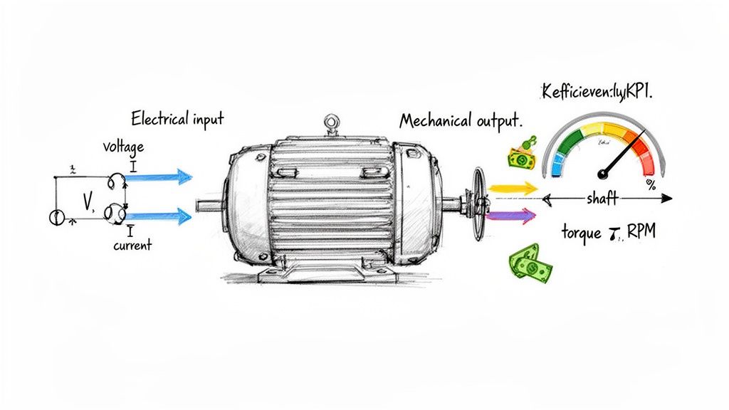
To really get a handle on this, you need to know the two sides of the equation:
Electrical Input Power: This is what the motor pulls from the grid. Measured in watts (W) or kilowatts (kW), it's the product of voltage, current, and something called the power factor.
Mechanical Output Power: This is the actual work the motor is doing at the shaft. You figure this out from its rotational speed (RPM) and the torque (rotational force) it's delivering.
The gap between these two numbers is where the waste happens. These losses are the enemy of an efficient operation.
Understanding Where the Energy Goes
Every single watt that doesn't help turn the shaft is wasted energy, and it almost always escapes as heat. This excess heat is what cooks a motor from the inside out, shortening its lifespan and setting you up for a premature failure.
The main culprits behind these energy losses are things like:
Copper Losses (I²R Losses): These come from the natural electrical resistance in the motor's copper windings.
Core Losses: Hysteresis and eddy currents create losses in the motor's magnetic steel core.
Mechanical Losses: Good old-fashioned friction in the bearings and wind resistance (drag) from the cooling fan.
Stray Load Losses: This is a catch-all for a bunch of other minor losses that are tricky to measure but add up as the motor's load increases.
The whole point of modern motor design and a solid maintenance program is to chip away at these losses. An inefficient motor isn't just an energy hog; it runs hotter, putting constant stress on its parts and making unplanned downtime a matter of when, not if. This is precisely why energy efficiency initiatives through strategic maintenance are so vital.
To give you a better grasp of what to look out for, here’s a quick breakdown of the factors at play.
Key Factors Influencing Motor Efficiency
The table below summarizes the primary elements that determine a motor's overall efficiency. It's a handy quick-reference for engineers trying to diagnose performance issues or specify new equipment.
Factor
Description
Impact on Efficiency
Motor Load
The percentage of the motor's full-rated load at which it is operating.
Motors are most efficient near 75-95% of their rated load. Efficiency drops significantly at loads below 50%.
Motor Design & Quality
The materials used (e.g., copper vs. aluminum windings, quality of steel) and the precision of manufacturing.
Higher-quality materials and better designs directly reduce copper, core, and stray load losses.
Operating Voltage
The stability and level of the supply voltage.
Consistent, balanced voltage minimizes electrical losses. Under- or over-voltage can increase heat and reduce efficiency.
Maintenance
Regular lubrication, cleaning of cooling fins, and bearing checks.
Proper maintenance reduces mechanical friction and ensures the motor runs cooler, preventing heat-related losses.
Power Factor
The ratio of real power (kW) to apparent power (kVA) in an AC circuit.
A low power factor means more current is needed to do the same work, increasing I²R losses in the windings.
Understanding these interconnected factors is the first step toward building a more robust and cost-effective operation.
The Financial Impact of Motor Inefficiency
The real-world dollar cost of poor motor efficiency is staggering. In developed regions like the United States and Europe, electric motors are responsible for a massive 40-50% of all industrial electricity consumption.
Even a small efficiency gain, when multiplied across a facility, can lead to huge savings. For example, just identifying and upgrading motors stuck in the 75-80% efficiency range can make a noticeable dent in your utility bills.
Think about a manufacturing plant with 500 motors. If you can boost the average efficiency from 85% to a premium level of 93%, you could slash annual energy costs by 15-20%. At an average electricity rate of $0.10/kWh, that one project could save the company over $100,000 a year.
This is exactly why knowing how to calculate motor efficiency is such a fundamental skill. It helps you pinpoint underperforming assets, build a business case for upgrades, and make maintenance decisions based on hard data.
Of course, other elements like the power factor play a big role in your overall electrical health. If you want to dive deeper, you can learn more about the power factor definition and its impact on your systems.
Gearing Up: The Right Tools for an Accurate Measurement
Before you even think about calculating motor efficiency, you have to be able to trust your numbers. And that trust comes down to one thing: the quality of your measurement tools. Using a basic multimeter when you need a power analyzer is like trying to do heart surgery with a butter knife—you might get a result, but you wouldn't bet a critical decision on it.
The whole game is about getting a crystal-clear picture of two things: the electrical power going in and the mechanical power coming out. Each side of that equation demands its own set of specialized gear.
Nailing the Electrical Input
First up, you've got to accurately measure the voltage, current, and power factor feeding the motor. This isn't a job for just any old clamp meter you have rattling around in your toolbox; the instrument has to fit the complexity of the job.
For a quick spot-check on a single-phase AC motor running under a steady load, a high-quality Digital Multimeter (DMM) with a clamp-on ammeter can give you a decent ballpark figure for voltage and current. It gets you in the neighborhood.
But for any serious efficiency audit—especially if you're dealing with three-phase systems or motors hooked up to a Variable Frequency Drive (VFD)—you absolutely must use a Power Quality Analyzer. There's no substitute.
A power quality analyzer is the non-negotiable tool for any professional-grade test. It measures voltage and current across all three phases at the same time, calculating the true power (kW), apparent power (kVA), and, most importantly, the true power factor. A standard DMM simply can’t do this, and relying on one will inject massive errors into your input power calculation right from the start.
When you're picking an analyzer, make sure it has these features:
True-RMS Measurement: This is critical for getting an accurate read on the distorted, non-sinusoidal waveforms that VFDs kick out.
Three-Phase Capability: It has to be able to watch all phases simultaneously to catch any imbalances.
Data Logging: The ability to record data over a period of time is huge. It lets you see how efficiency shifts as the motor's load changes.
Without this level of instrumentation, your entire effort to measure efficiency accurately crumbles before you've even started.
Quantifying the Mechanical Output
Once you have a solid handle on the electrical input, it's time to measure what the motor is actually doing at the shaft. This means measuring its rotational speed and the amount of torque it's delivering to the load.
Measuring Rotational Speed (RPM) The go-to tool here is a Tachometer. You’ll generally run into two types:
Contact Tachometer: This has a small wheel or tip you press right against the end of the motor shaft. It's direct, simple, and gets the job done.
Non-Contact (Photoelectric) Tachometer: This type uses a laser or an infrared beam aimed at a small piece of reflective tape stuck to the shaft. It's much safer for high-speed machinery or when the shaft is tough to get to.
For most fieldwork, a good handheld digital tachometer with an accuracy of ±1 RPM is more than enough to get the speed data you need for the output power formula.
Measuring Torque Here’s where things can get tricky in the field. Measuring torque accurately often requires some pretty specialized equipment.
In-Line Torque Sensor: These are installed right between the motor and the load, where they directly measure the rotational force. They're incredibly accurate but mean you have to uncouple the machinery, which makes them a better fit for a workshop or lab environment than a quick field test.
Dynamometer: A dynamometer, or "dyno," is the gold standard for motor testing. It doesn't just measure torque and speed; it can also act as a programmable load. This lets you test the motor across its entire operating range and map out a beautiful, detailed efficiency curve.
Calculating Efficiency with the Direct Measurement Method
When you need hard, undeniable data on how a motor is really performing, nothing beats the direct measurement method. This is the gold standard for a reason. It involves simultaneously measuring the electrical power going into the motor and the mechanical power coming out of it while it's hooked up to a real-world load.
This approach takes all the guesswork out of the equation. It provides a clear, direct, and highly accurate snapshot of the motor's efficiency right then and there. What goes in must either come out as useful work or be lost as heat and noise. Direct measurement quantifies this relationship perfectly.
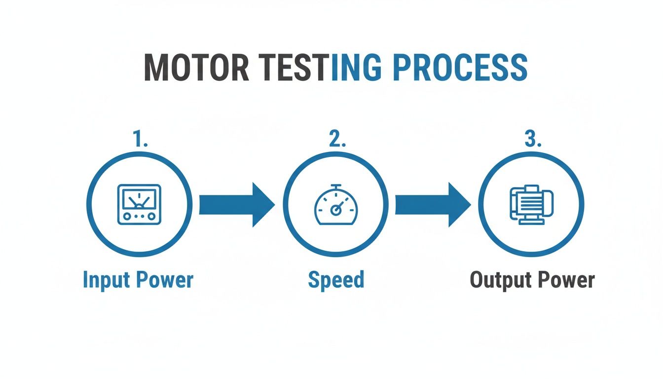
This diagram breaks down the basic setup for gathering the data you need.
As you can see, you’ve got a power analyzer on the input side and a combination of a tachometer and a dynamometer on the output. This setup gives you all the variables needed for a rock-solid efficiency calculation.
Mastering the Input Power Formulas
First up, you need to nail down the electrical input power (P_in), which we measure in watts (W). The formula you'll use depends on whether you're dealing with a single-phase or a three-phase system—and in most industrial settings, you'll be working with three-phase.
For Single-Phase Motors:
P_in = Voltage (V) × Current (I) × Power Factor (PF)
For Three-Phase Motors:
P_in = Voltage (V) × Current (I) × Power Factor (PF) × √3
That extra factor, the square root of 3 (~1.732), is the magic number for three-phase calculations. It accounts for the phase difference in the power delivery. For the most accurate reading, make sure you're using the average line-to-line voltage and the average line current.
Measuring the Mechanical Output Power
Next, we need to figure out the mechanical output power (P_out). This is the actual rotational work the motor is delivering at the shaft, and it's a product of both its speed and its torque.
When you're working with standard imperial units, the formula looks like this:
The number 5252 is a conversion constant that gets everything into horsepower. But to compare apples to apples, we need both input and output in the same units. That means converting horsepower to watts. Luckily, that’s easy:
1 Horsepower = 746 Watts
So, your final output power is simply P_out (HP) × 746. Now you have both P_in and P_out in watts, and you’re ready for the final step.
Bringing It All Together: A Worked Example
Let’s walk through a real-world scenario. You're testing a 50 HP, 460V three-phase motor that runs a big pump at a manufacturing plant. You’ve got your power analyzer hooked to the motor's input and a dynamometer on the output shaft.
You let the motor run for a bit to get up to a stable operating temperature, then you load it up and record the numbers:
Average Line-to-Line Voltage (V): 462 Volts
Average Line Current (I): 58 Amps
Power Factor (PF): 0.88
Shaft Speed (RPM): 1775 RPM
Shaft Torque (lb-ft): 145 lb-ft
Alright, let's crunch the numbers.
1. Calculate Input Power (P_in): Using our three-phase formula: P_in = 462 V × 58 A × 0.88 PF × 1.732 = 40,841 Watts
2. Calculate Output Power (P_out): First, let's get the horsepower: P_out (HP) = (145 lb-ft × 1775 RPM) / 5252 = 48.98 HP
Now, convert that to watts: P_out (W) = 48.98 HP × 746 W/HP = 36,543 Watts
Our direct measurement shows this motor is operating at 89.5% efficiency under this specific load. This is why direct testing is so valuable—it’s not an estimate. It’s a definitive performance benchmark.
The Importance of Testing at Multiple Load Points
Here’s something a lot of people miss: a single efficiency number at full load doesn't tell the whole story. Very few motors run at 100% load all day long. Their efficiency changes dramatically depending on how hard they're working.
For a complete picture, you need to test at various load points—I always recommend 25%, 50%, 75%, and 100% of the motor's rated capacity.
When you plot these results, you get an efficiency curve. This curve is infinitely more useful for understanding real-world energy use. It will almost always show you that peak efficiency happens somewhere between 75% and 100% load, and it drops off a cliff below 50%. Knowing this helps you right-size motors for their jobs and avoid the classic, costly mistake of running a huge motor for a tiny task.
Using the Indirect Method for In-Service Motors
So, what do you do when you need a motor's efficiency numbers, but taking the equipment offline for a full dynamometer test just isn't an option? In the real world of a busy plant, you can't always shut down a critical production line. This is exactly where the indirect method, also known as the segregated loss method, proves its worth.
Instead of trying to measure mechanical output directly, this approach works backward. You start by accurately measuring the electrical power going into the motor. Then, you systematically track down and quantify all the internal energy losses. Whatever is left over after you subtract those losses is your useful mechanical output power.
The formula itself is straightforward:
Efficiency (%) = (Input Power – Total Losses) / Input Power × 100
This technique is a lifesaver for any maintenance manager or plant engineer who needs to assess the health of installed equipment without causing a major headache. It gives you a reliable efficiency figure for a motor that’s already hard at work, driving a pump, fan, or conveyor.
Breaking Down the Four Key Motor Losses
To get this right, you have to play detective and hunt down four distinct types of energy loss. Each one represents a different way the motor bleeds off electrical energy as something other than useful rotational force—mostly heat.
Copper Losses (I²R Losses): These are the most common culprits. They're caused by the simple electrical resistance in the copper windings of the stator and rotor. As current flows, the windings heat up, and that heat is pure energy loss.
Core Losses: These happen inside the motor's laminated steel core. They're a combination of hysteresis (energy lost from constantly reversing the magnetic field) and eddy currents (tiny, wasteful currents induced in the core material itself).
Mechanical Losses: This bucket covers pure friction. We're talking about friction in the motor's bearings plus the "windage" created by the internal cooling fan and other spinning parts pushing against the air.
Stray Load Losses: This is the catch-all category for a bunch of other complex losses that change depending on how hard the motor is working. They come from things like leakage flux and other secondary effects that are tricky to pin down but still contribute to the overall inefficiency.
By carefully segregating and adding up these individual losses, you can build a surprisingly accurate picture of the total energy going to waste.
The Testing Procedure for Segregated Losses
Pinpointing each type of loss requires a couple of specific tests. The two most important ones are the no-load test and the stator resistance measurement.
Stator Resistance Test: This is a simple but absolutely critical first step. You'll use a high-precision ohmmeter to measure the DC resistance across the motor leads. This value is essential for calculating your copper losses (I²R) later on. A pro tip: make sure you do this when the motor is at a known, stable temperature, because resistance changes with heat.
No-Load Test: For this one, you uncouple the motor from its load and let it run freely at its rated voltage and frequency. You measure the input power it's drawing. Since the motor isn't doing any real work, the power it's consuming is purely to overcome its own internal losses—the core losses and mechanical losses combined.
Think of it like a financial audit, but for watts instead of dollars. By combining the results from these tests with the input power you measure under normal operating load, you can piece together the motor's complete energy balance sheet.
Direct vs. Indirect Efficiency Measurement Methods
For engineers and managers deciding how to approach motor testing, understanding the pros and cons of each method is key. The direct method is the gold standard for accuracy but requires taking the motor out of service. The indirect method offers a practical alternative for live, in-service equipment.
Here's a quick breakdown to help you choose the right tool for the job.
Attribute
Direct Method (Input-Output)
Indirect Method (Segregated Loss)
Accuracy
Highest (typically ±1%)
Very good (typically ±3%)
Equipment
Dynamometer, torque sensor, power analyzer
Power analyzer, ohmmeter, tachometer
Disruption
High (motor must be removed from service)
Low (can be done on an installed motor)
Best For
Lab testing, new motor acceptance, R&D
In-field diagnostics, energy audits, troubleshooting
Complexity
Mechanically complex setup
Electrically focused tests
Standard
IEEE 112 (Method B)
IEEE 112 (Method E) / IEC 60034-2-1
Ultimately, while the direct method provides the most precise answer, the indirect method delivers actionable data without shutting down your operations, making it an invaluable tool for real-world facility management.
The segregated loss method, which is rooted in standards like IEEE 112 and was refined by organizations like Ontario Hydro back in the 1980s, gives us a non-intrusive way to see what's happening inside. In fact, research shows its accuracy is typically around ±3%. That's a huge improvement over less reliable estimates. A 1995 ACEEE paper on motor efficiency testing methods is a great resource if you want to dig into the historical data.
A Practical Example with a 100 HP Motor
Let's walk through a scenario. You're tasked with assessing a 100 HP, 460V three-phase motor out on the plant floor. The nameplate tells you it should pull about 75 kW at full load. You run the segregated loss tests and get these numbers:
Copper Losses (I²R): 5 kW
Core Losses: 4 kW
Mechanical Losses: 3 kW
Stray Load Losses (estimated): 3 kW
Add them up, and your total calculated losses are 5 + 4 + 3 + 3 = 15 kW.
Since you measured an input of 75 kW, the actual mechanical output is 75 kW – 15 kW = 60 kW.
Now, you can calculate the real-world efficiency: Efficiency = (60 kW / 75 kW) × 100 = 80%
That's a problem. A modern NEMA Premium motor of this size should be hitting 93.6% efficiency. This hard data gives you everything you need to build the business case for a replacement. The savings get even bigger when that motor is driving equipment where you can fine-tune the output. For more on that, see our guide on AC motor variable speed options.
Common Mistakes and Best Practices for Reliable Results
Knowing the formulas and having the right tools is a great start, but it's only half the battle. Out in the real world, the industrial environment is messy. It's full of variables that can—and will—throw off your measurements, leaving you with data that looks fine on paper but doesn't reflect what's actually happening.
Experience teaches you where the traps are. I've seen it time and again: avoiding a few common mistakes is what separates a truly meaningful energy audit from an academic exercise. This is the stuff that makes your results not just correct, but reliable.
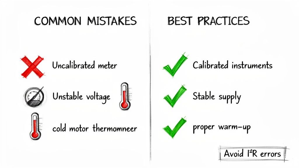
The Pitfall of Cold Testing
One of the most common blunders I see is testing a motor right after it's been turned on. A cold motor will give you misleading results every single time. Why? Because the electrical resistance of its copper windings changes dramatically with temperature.
As a motor runs, it heats up. That heat raises the resistance of the windings. Thanks to Ohm's Law, higher resistance means higher copper losses (I²R losses), which drags down the motor's real-world efficiency.
Best Practice: Let the motor run under its typical load for at least an hour, or until its frame temperature stops climbing. This "thermal soak" is crucial. It ensures your power readings reflect its true, steady-state performance.
Ignoring Your Instrument Calibration
This one should be obvious, but it’s surprisingly common. Using uncalibrated instruments is a recipe for disaster. A power analyzer that's off by just a couple of percentage points can create a cascade of errors, making your final efficiency calculation totally useless.
Think of it this way: your calculations are built on a foundation of numbers your tools provide. If that foundation is shaky, the whole structure you build on top of it will be worthless.
Calibrate Regularly: Every piece of test equipment, especially your power analyzer and torque sensors, needs a valid calibration certificate. Stick to the manufacturer's recommended interval, which is usually once a year.
Do a Sanity Check: Before a big test, I always try to do a quick check on a known, stable source if possible. It’s a simple way to confirm your gear is behaving as expected before you sink hours into collecting bad data.
Document Everything: Keep a log of your instrument serial numbers and their last calibration dates. This is basic good practice for any serious quality or predictive maintenance program.
Understanding the Impact of Power Quality
Dirty power can wreak havoc on motor performance and completely skew your efficiency numbers. Things like voltage imbalance between phases, low voltage, or harmonic distortion from VFDs all force a motor to run hotter and less efficiently.
For example, a voltage imbalance of just 2% can crank up motor losses by nearly 20% and cause a serious temperature rise. If you miss this, you'll end up blaming the motor for poor performance when the real culprit is the power supply.
Check Voltage Stability: Before you start, make sure the supply voltage is stable and within ±10% of the motor's nameplate rating.
Measure Phase Balance: For three-phase systems, the voltage between each phase needs to be balanced. Anything over a 1% imbalance is a red flag that needs to be investigated.
Use True-RMS Meters: This is non-negotiable. If there's a Variable Frequency Drive (VFD) in the mix, you absolutely must use a true-RMS power analyzer. A standard meter can't accurately read the messy, non-sinusoidal waveforms from a VFD, which will lead to wildly inaccurate input power data.
Following these field-tested practices ensures your efforts produce data you can actually trust and act on. If you ever run into performance problems you just can't pin down, getting a professional opinion is a smart move. You can learn more about specialized troubleshooting in our guide to electric motor service options.
Common Questions on Motor Efficiency
Even after you get the hang of the direct and indirect methods, a few practical questions always pop up. That's perfectly normal. Diving into the nitty-gritty of motor efficiency calculations always brings up some real-world headaches worth tackling head-on.
Let's walk through some of the most common questions we hear from folks in the field.
What's the Real Difference Between NEMA and IEC Standards?
This is a huge point of confusion, especially for teams sourcing equipment for international projects. At a high level, the National Electrical Manufacturers Association (NEMA) sets the bar in North America, while the International Electrotechnical Commission (IEC) standards are the global benchmark.
They’re chasing the same goal but use different language.
NEMA keeps it simple with "Energy Efficient" and the higher-tier "Premium Efficient."
IEC uses a numbered system, climbing from IE1 (Standard Efficiency) all the way up to IE5 (Ultra-Premium Efficiency).
While their testing methodologies are pretty similar, the actual efficiency targets for each class can differ. The most important thing is to know which standard governs your project. That way, you can specify—and later verify—the right motor for the job without any expensive surprises.
How Does a VFD Mess with My Efficiency Calculations?
Ah, the Variable Frequency Drive (VFD). It's a game-changer for control, but it definitely complicates your efficiency math. First off, the VFD itself isn’t 100% efficient. It has its own internal losses, usually burning off 2-5% of the power it draws. This means your total system efficiency (VFD + motor) will always be a few points lower than the motor's efficiency alone.
But the bigger issue is the VFD's output. It's not a clean, smooth sine wave like you get from the grid. This choppy, distorted waveform will completely fool a standard multimeter, leading to wildly inaccurate input power readings. You absolutely need a true-RMS power analyzer to get a correct measurement.
If you want to isolate the motor's true performance, you have to measure power at the VFD's output terminals—the lines running straight to the motor. Don't measure at the VFD's input. This is probably the single most common mistake people make when testing VFD-driven motors.
Can I Just Trust the Nameplate Efficiency Rating?
Think of that nameplate number as the motor's best-case scenario—achieved in a lab, under perfect conditions, at its full rated load. It’s a decent starting point, but you have to take it with a grain of salt in the real world.
Several things can drag a motor's operating efficiency well below what’s stamped on the side:
Partial Loading: Efficiency plummets once a motor operates below 50% of its rated load. This is incredibly common.
Voltage Imbalance: Even a small discrepancy between phases creates a huge drag on performance and generates excess heat.
High Temps: A hot environment increases winding resistance, which directly translates to lower efficiency.
For any serious energy audit or a critical piece of machinery, there's just no substitute for getting your own field measurements.
How Often Should I Be Testing My Critical Motors?
There's no one-size-fits-all answer here, but the best practice is to build a testing schedule based on how critical the motor is. A great place to start is by getting a detailed baseline efficiency test done right after a new motor is commissioned.
From there, aim to re-test every three to five years. You should also make it standard procedure to test a motor after any major repair, especially a rewind. A sloppy rewind can easily slash efficiency by 1-2%, and you need to know if you're now running a less-efficient machine. Tying current monitoring into your condition monitoring program is another smart move—it can give you an early heads-up that performance is degrading and it's time for a closer look.
At E & I Sales, we provide the premium electric motors and integrated control systems that form the backbone of efficient industrial operations. From specification to commissioning, we help you build reliable, high-performance systems. Find out how we can support your next project.
Predictive maintenance is a pretty simple concept at its core: use real-time data and a bit of smarts to see equipment failures coming before they shut you down. It’s all about getting ahead of the problem.
This approach lets your maintenance crew schedule repairs during planned downtime instead of scrambling to fix things after a catastrophic failure. It’s a move away from reactive, break-fix cycles and toward preventing costly disruptions in the first place, which drops right to your bottom line through significant cost savings and way better efficiency.
Why Predictive Maintenance Is a Game Changer for Manufacturing
Let's cut through the buzzwords and talk numbers. Unplanned downtime isn't just a headache; it's a massive financial drain. Every minute a critical production line sits idle, you're losing money on output, wasting material, and paying for labor that can't work.
This is exactly the problem predictive maintenance was designed to solve.
It fundamentally changes how you think about maintenance. Instead of waiting for a motor to seize or a conveyor to grind to a halt, you’re using technology to constantly listen to the health of your equipment.
The Staggering Cost of Reactive Maintenance
The real gut punch of unplanned downtime is the domino effect it creates. Think about it: a single bearing failure in a critical motor can bring an entire production line to its knees. Suddenly, you're facing missed deadlines, unhappy customers, and emergency repair costs that are always, always higher than planned work.
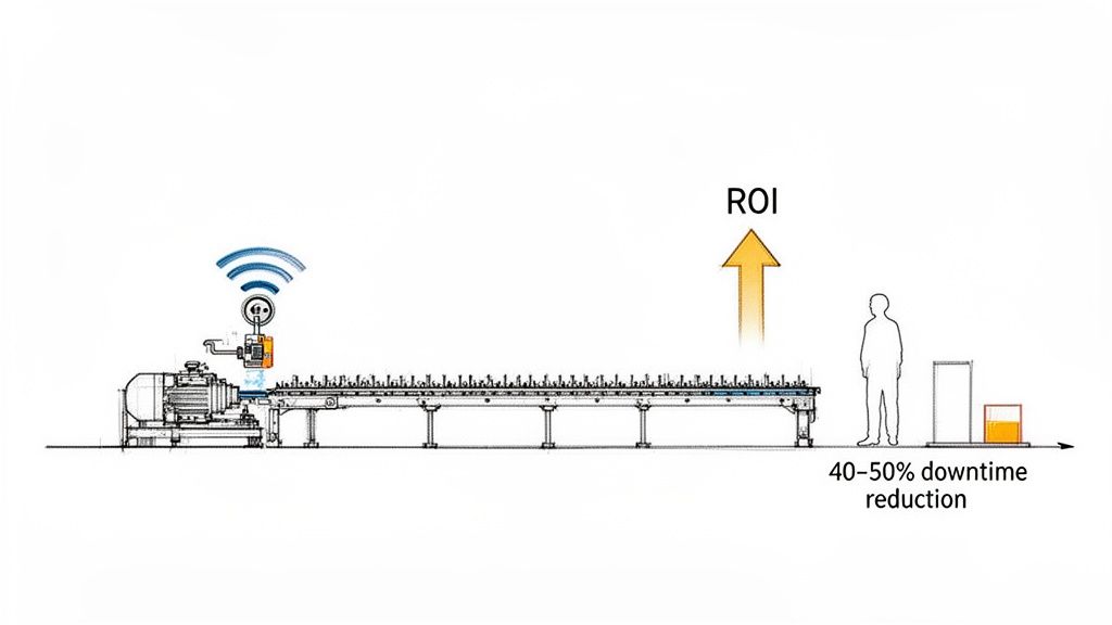
Siemens actually put a number to this, estimating that manufacturers lose a staggering $260 billion annually because of unplanned downtime.
The flip side? The same research shows that facilities putting predictive maintenance to work are cutting those maintenance costs by 40% and slashing unplanned machine downtime by up to 50%. You can dig deeper into these downtime reduction findings yourself. This isn't just a small improvement; it's a real competitive edge.
How Predictive Maintenance Delivers Tangible ROI
The return on a well-executed predictive maintenance program is crystal clear. When you can see failures coming, you can schedule repairs with surgical precision, which means you're not wasting labor or tying up cash in spare parts you don't need yet.
This leads to some serious benefits:
Drastic Downtime Reduction: Catching problems early means you can schedule fixes during planned shutdowns. Unexpected stops become manageable tasks.
Lower Maintenance Costs: Proactive repairs are just cheaper. You avoid overtime labor and the premium you pay for rush-ordered parts.
Extended Asset Lifespan: Equipment that's properly monitored and maintained simply runs better and lasts longer. You get more out of your capital investments.
Improved Safety: Identifying potential failures before they become catastrophic helps prevent accidents and makes the plant floor a safer place to be.
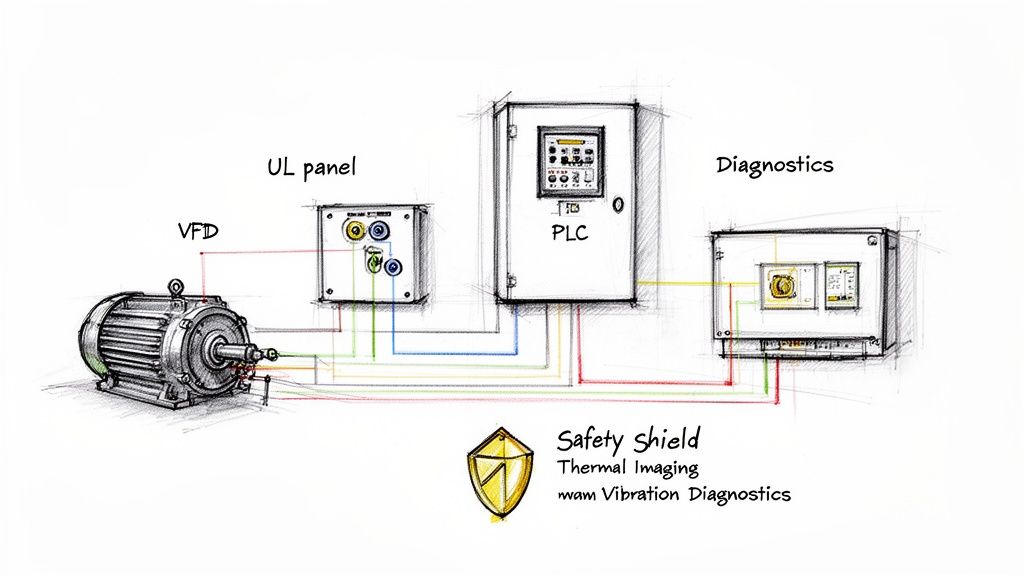
For the OEMs and system integrators out there, this is where you can add huge value. Building predictive maintenance capabilities directly into your custom UL control panels and motor control systems transforms a standard electrical package into an intelligent asset that actively protects your customer's operation.
The bottom line is that predictive maintenance isn't just for the big guys anymore. With IIoT sensors and cloud analytics becoming so accessible, it’s now a vital tool for any facility that's serious about running a tight ship. It's about turning data into decisions and building a more resilient, efficient, and profitable operation.
Building Your Predictive Maintenance Technology Stack
Putting together the right technology for predictive maintenance can seem overwhelming. But really, it’s about picking practical tools that solve specific problems on your factory floor. You don't need a gold-plated, overly complex system from the get-go. What you need is a solid foundation that gets the right data and turns it into clear instructions for your maintenance crew.
This blueprint breaks down the core pieces you'll need, from the sensors on the machines to the software that ties into your daily operations.
Starting with the Right Sensors and Gateways
It all starts with data. And that data comes from sensors. Choosing the right sensor is everything; you have to pick one that can actually measure the specific failure you’re trying to get ahead of.
Vibration Sensors (Accelerometers): These are the absolute workhorses for anything that spins—motors, pumps, fans, you name it. They pick up on imbalances, misalignments, and bearing wear way before a failure becomes catastrophic.
Thermal Sensors (Infrared): Heat is the classic tell-tale sign of trouble. Whether it’s a loose connection in an electrical cabinet or friction in a mechanical system, thermal sensors will spot it.
Ultrasonic Sensors: These are fantastic for hearing things humans can't. They detect high-frequency sounds that point to compressed air leaks, electrical arcing, or the very first signs of bearing degradation.
Once a sensor grabs that raw data, it has to go somewhere. That's the job of an IIoT (Industrial Internet of Things) gateway. Think of it as the bridge between your physical equipment and your digital systems. It pulls data from multiple sensors and shoots it securely over to your network.
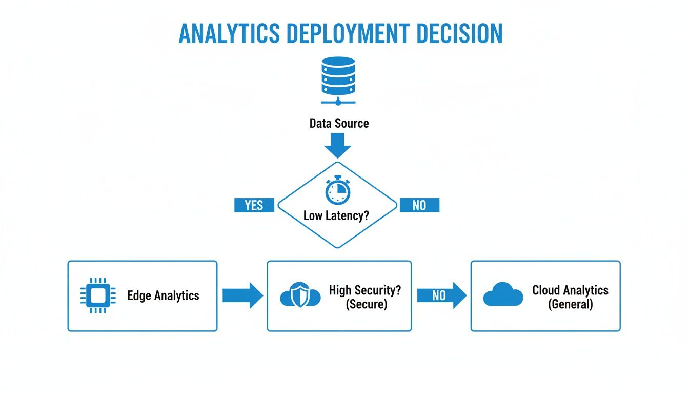
Edge vs. Cloud Analytics: Where to Process Your Data
With data streaming in, you’ve got a big decision to make: where do you analyze it? This choice between edge and cloud computing really impacts your costs, response time, and security.
Edge computing means you process the data right there on or near the factory floor, using things like industrial PCs or smart gateways. This is your go-to when speed is non-negotiable. For instance, if a high-speed packaging machine needs an immediate shutdown signal, you can’t wait for data to travel to the cloud and back.
Cloud computing, on the other hand, is all about sending your data to a remote server for some serious number-crunching. This is perfect for spotting long-term trends across your entire plant and using powerful machine learning models that need massive processing power.
Deciding between the two depends heavily on your specific application's needs for speed, cost, and security.
Edge vs Cloud Analytics for Predictive Maintenance
Factor
Edge Computing
Cloud Computing
Latency
Very low (milliseconds)
Higher (seconds)
Bandwidth Use
Minimal
High
Initial Cost
Higher (hardware on-site)
Lower (subscription-based)
Scalability
More complex to scale
Easily scalable
Data Security
Data stays on-premise
Requires robust cloud security
Honestly, a hybrid approach often works best. Let edge devices handle the urgent, time-sensitive alerts on the floor, while the cloud crunches data in the background to build smarter, more refined predictive models over time.
Integrating with Your Existing Systems
A predictive maintenance system that doesn't talk to anything else is just a science project. Its real value is unlocked when it integrates smoothly with the tools your team already relies on.
The ultimate goal is to create a closed loop: a sensor detects an anomaly, the analytics platform confirms a pending failure, and a work order is automatically generated in your CMMS with all the necessary details.
This kind of integration is where the efficiency gains happen. When your predictive data flows straight into your CMMS (Computerized Maintenance Management System) or ERP (Enterprise Resource Planning) software, you kill manual data entry and make sure alerts never get lost in the shuffle. It’s what turns a prediction into a scheduled, proactive repair.
As you build out your tech stack, it’s worth checking out the top predictive analytics software solutions to see what’s out there. Many of these platforms come with ready-made connectors for common CMMS and ERP systems, which can save a ton of headaches.
For system integrators and OEMs, the custom UL control panel is the perfect place to bring all this together. A well-designed panel can house the IIoT gateways, edge hardware, and motor controls in one neat, compliant package. It simplifies installation and gives your customers a standardized, scalable solution. You can dive deeper into modern industrial controls and automation to see how it's done. By building the technology right into the control system, you're delivering a turnkey product that’s ready for predictive maintenance from day one.
Developing a Data Strategy That Actually Works
So you’ve got the shiny new sensors and a gateway ready to go. That's a great start, but the real power behind a winning predictive maintenance for manufacturing program isn't the hardware—it's having a smart data strategy. Without one, you’re just collecting a mountain of digital noise. A solid plan is what turns those raw sensor readings into the kind of clear, actionable intelligence that stops downtime in its tracks.
This isn't about trying to boil the ocean. The key is to be surgical. Your first move should be to zero in on your most critical assets. Forget monitoring everything at once. Pinpoint the machines whose failure would trigger the biggest operational and financial migraines. That’s your starting line.
Identifying Critical Assets and Failure Modes
Once you've got your list of VIP equipment, the next question is simple: how do they usually break? Every machine has its own quirks and common failure points. A centrifugal pump, for instance, might be notorious for bearing wear or seal failure. A robotic arm, on the other hand, might be more prone to gearbox trouble or actuator drift.
This is where you bring in your veteran maintenance techs. These folks have invaluable "tribal knowledge." They know which machines are the real troublemakers and have learned to spot the subtle warning signs over years of hands-on experience. Getting these specific failure modes documented is absolutely crucial—it tells you exactly what data you need to hunt for.
From there, you need to establish a clear baseline of what "normal" operation looks like for each asset. This means capturing operational data—vibrations, temperatures, current draw—while the machine is running perfectly. This baseline becomes your golden standard, the benchmark you'll measure everything against.
Key Takeaway: A killer data strategy starts with quality, not quantity. Focus on capturing the right data from your most critical assets to predict their most common and costly failures. This targeted approach gets you quick wins and builds momentum for the program.
Choosing the Right Predictive Algorithms
With a clean, focused stream of data flowing, you can finally start applying predictive models to find the patterns that scream "impending failure." The algorithm you pick really depends on the complexity of the machine and its failure mode.
Regression Models: These are your go-to for simpler, linear relationships. Think about predicting the remaining useful life (RUL) of a filter based on a steady increase in pressure drop readings. It's a straightforward cause-and-effect scenario.
Classification Models: These are perfect for sorting an outcome into a few buckets. A classification algorithm could analyze vibration data from a motor and confidently label its state as "healthy," "moderate bearing wear," or "imminent failure."
Machine Learning (ML) & AI: For the really complex stuff, like a multi-axis CNC machine or a robotic cell, you need to bring in the heavy hitters. Machine learning can juggle dozens of variables at once, detecting subtle, non-linear patterns that no human could ever hope to spot.
A huge part of this is deciding where to run these analytics—on the edge, right next to the machine, or in the cloud. This isn't a trivial choice.
The logic is pretty clear: if you need near-instant responses or you're dealing with sensitive data, edge computing is the way to go. For less time-critical, big-picture analysis where you need massive computational power, the cloud is your best bet.
Turning Predictions into Actionable Alerts
Here’s where the rubber meets the road. All the fancy modeling in the world is useless if it doesn't translate into a clear, actionable alert for your maintenance team. A notification that just says, "Anomaly Detected on Motor 7," is more annoying than helpful.
A good alert gives the team context. It should specify the asset, the suspected problem (e.g., "High probability of outer race bearing fault"), a severity level, and a concrete recommended action. That's the difference between creating more digital noise and actually empowering your team to get ahead of a problem.
This entire data lifecycle—from pinpointing failure modes to generating specific, intelligent work orders—is the backbone of any predictive maintenance for manufacturing strategy that works in the real world. It’s how you ensure your investment doesn’t just spit out interesting charts, but delivers real, tangible results by keeping your lines running.
Launching a Pilot Program to Ensure Success
Jumping headfirst into a full-scale predictive maintenance rollout across an entire facility is a recipe for disaster. I've seen it happen. A much smarter approach is to start small, prove the concept, and build momentum with a well-planned pilot program. This isn't about being hesitant; it's about being strategic.
Think of a successful pilot as your internal case study. It’s your chance to work out the kinks in a controlled environment, show real, tangible value to the people holding the purse strings, and create a scalable blueprint for the rest of the plant. Without it, you risk burning through a lot of capital and losing internal support before the project ever really gets off the ground.
Selecting Your First Critical Assets
First things first: you have to choose where to focus your efforts. Don't try to monitor everything at once. Pick a small group of 3-5 critical assets that give you a good mix of potential challenges and quick wins.
So, how do you pick the right ones? Look for equipment that is:
Operationally Critical: Pinpoint the machines whose failure brings production to a screeching halt. These are your high-impact targets where preventing even a little downtime delivers immediate, highly visible value.
Known Troublemakers: Your maintenance team knows which machines are always on their radar. These assets usually have a long and sordid history of failures, which, conveniently, gives your predictive models a rich dataset to learn from.
Representative of Other Assets: Choose equipment that’s common throughout your facility. If you can prove the system works on one specific model of a pump or motor, it makes the conversation about scaling to dozens of similar assets a whole lot easier.
For instance, a packaging OEM might target a single, high-speed case erector that's notorious for jamming up due to motor fatigue. Or a plant engineer could focus on a critical air compressor that, if it fails unexpectedly, would shut down multiple production lines. These are the specific, high-value targets that make for a compelling pilot.
Defining Clear Success Criteria
Once you have your assets picked out, you absolutely have to define what success looks like. Vague goals like "improve efficiency" just won't cut it. You need concrete, measurable Key Performance Indicators (KPIs) to prove the pilot's worth.
Pro Tip: Your single most powerful metric in a pilot program is the "catch." A catch is a documented instance where the system correctly predicted a failure, an alert went out, and your team intervened to prevent an unplanned shutdown. Every single catch is a powerful story of an averted disaster and money saved.
Track your success criteria meticulously. You're essentially building a business case using real data from your own facility.
Key Metrics for a Pilot Program
Metric
What It Measures
Example Goal
Number of "Catches"
How many failures were successfully predicted and prevented.
Log at least 3 verified catches in 90 days.
Reduction in Unplanned Downtime
The direct impact on production availability for the pilot assets.
Decrease unplanned downtime on pilot assets by 40%.
Maintenance Cost Avoidance
The estimated savings from avoiding emergency repairs and overtime.
Show $25,000 in cost avoidance over the pilot period.
Alert Accuracy
The ratio of valid alerts to false positives.
Achieve an alert accuracy rate of 85% or higher.
Creating a Roadmap for Scaling
A successful pilot is just the beginning. The real prize is using its success as a launchpad for a facility-wide rollout. This demands a clear, practical scaling plan that addresses both the technology and, just as importantly, the people.
Your roadmap should be all about standardization. This is where creating pre-configured hardware packages, like custom UL control panels, becomes a massive advantage. Instead of reinventing the wheel for every new asset, you can develop a standardized panel that includes all the necessary sensors, IIoT gateways, and edge hardware. This "plug-and-play" approach drastically cuts down on installation time and engineering costs as you scale.
Don't forget to invest in your team. A common mistake is rolling out new technology without preparing the people who have to use it every day. Develop a structured training program for your maintenance staff. This needs to cover more than just how to respond to alerts; it should touch on the basic principles behind the analytics. For teams coming from a more traditional maintenance schedule, our guide on building a solid preventive maintenance schedule template can provide a great foundational understanding of maintenance planning.
By proving the value on a small scale and then creating a standardized, repeatable process for expansion, you transform predictive maintenance for manufacturing from a one-off experiment into a core operational strategy.
Measuring ROI and Overcoming Common Hurdles
Let's be honest: a predictive maintenance program is just an expensive science experiment until it proves its worth. To get buy-in and keep it, you have to connect the dots between the technology and the bottom line. It's not enough to just say you're preventing downtime; you need to build a rock-solid, data-backed case for it.
This isn't just about satisfying the front office. A clear story of improvement, backed by hard numbers, is what will convince the teams on the shop floor that this new way of working is actually making their lives easier.
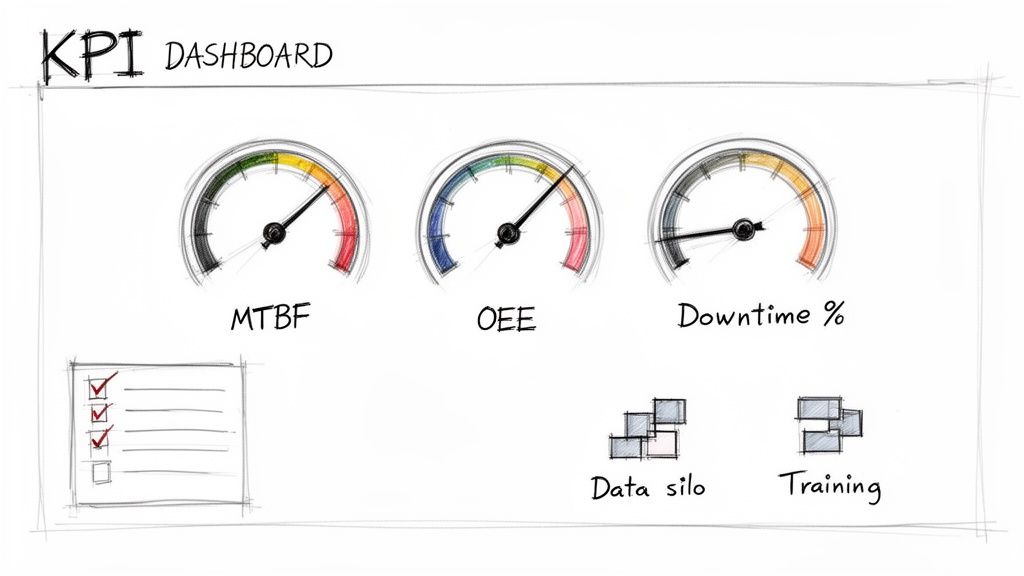
Tracking the Right KPIs to Prove Value
Reducing downtime is the obvious win, but it’s only one piece of the puzzle. A truly compelling business case looks at the whole picture—efficiency, asset health, and how effectively your maintenance resources are being used.
Here are the metrics that really matter:
Mean Time Between Failures (MTBF): This is the classic measure of reliability. When your MTBF starts climbing, you have definitive proof that your equipment is breaking down less often. It’s the most direct validation of your predictive strategy.
Overall Equipment Effectiveness (OEE): The gold standard for a reason. OEE rolls up availability, performance, and quality into one powerful number. Improving it shows you're not just stopping failures but actively creating more production capacity.
Maintenance Cost per Unit: This one really hits home. It ties every dollar you spend on maintenance directly to your plant's output. When this number goes down, you're showing you’re doing more with less.
Prevented Downtime Incidents: Think of this as your "good catches" log. Every time the system flags a potential failure that you confirm and fix proactively, you log it. Each entry is a tangible win and a story of averted disaster.
You’re not just tracking numbers; you’re quantifying the shift from a reactive, costly break-fix culture to a proactive, value-driven one. When you can show a 20-30% increase in MTBF or a 5-10% jump in OEE, the conversation about ROI becomes much easier.
Navigating Common Implementation Hurdles
Rolling out a predictive maintenance program isn’t always a smooth ride. Even with the best tech, you're going to hit some real-world bumps. Knowing what they are ahead of time—and having a plan—is what separates the successful projects from the ones that stall out.
The industry is moving this way, but old habits die hard. While 30-40% of plants are now using predictive maintenance, a whopping 71% still rely on traditional preventive schedules. But the payoff for pushing through is huge. Teams that make the leap report impressive results: 85% see better downtime forecasting, and 55% of plants report a boost in maintenance staff productivity. As these key maintenance statistics show, tackling the challenges head-on is well worth the effort.
The Challenge of Data Silos and Skills Gaps
One of the first brick walls you’ll likely run into is getting to the data. Critical information is often stuck in separate systems—the control system, the historian, the CMMS—and none of them want to talk to each other. These data silos make it impossible to get a complete picture of asset health.
Your Playbook: Focus on integration from day one. Use IIoT gateways and modern software platforms with solid APIs to start pulling that data into one place. Don't try to boil the ocean; start with the most critical data points for your pilot assets and build from there.
At the same time, you might realize your team of mechanical wizards isn't as comfortable with data analytics. That’s perfectly normal.
Your Playbook: Invest in training that’s practical, not academic. Show them what the data means for the machines they know inside and out. Find a technology partner who offers real support, not just a login. Many companies find it incredibly valuable to lean on professional engineering maintenance services to fill that knowledge gap in the beginning.
Overcoming Resistance from Seasoned Teams
This might be the biggest hurdle of all: culture. Your veteran technicians have spent decades relying on their gut—the sounds, the vibrations, the feel of a machine—to know when something's wrong. A new dashboard spitting out alerts can feel like a direct challenge to their experience.
Your Playbook: Bring them into the fold immediately. Make them a core part of the project, not just the recipients of it. Ask them which assets are the biggest headaches and what the common failure modes are. When the system generates an alert, treat it as a new tool in their toolbox. Frame the conversation collaboratively: "Hey, the data suggests we should look at the bearing on Motor 12. What are you hearing over there?"
This approach builds trust, shows respect for their expertise, and turns potential skeptics into your biggest advocates.
Sorting Out the Details: Your Predictive Maintenance Questions Answered
Even the most straightforward projects come with their share of questions, and shifting to a predictive maintenance model is a big step. We get it. Over the years, we've heard just about every question in the book from OEMs, plant managers, and system integrators.
Here are the answers to the most common ones we field.
Isn't This Just a Fancier Version of Preventive Maintenance?
This is easily the question we hear most, and the difference is fundamental. Think of it this way: Preventive maintenance is all about the calendar. You service a machine every 1,000 hours or every six months, whether it needs it or not. It's a "just-in-case" approach.
Predictive maintenance, on the other hand, is driven by real-world conditions. It uses live data from your equipment to tell you precisely when a component is starting to fail. Instead of changing gearbox oil on a fixed schedule, you change it when the viscosity and particulate data says it's time.
You’re moving from a routine schedule to a data-driven, "just-in-time" intervention. This simple shift is powerful—it can cut maintenance costs by 25-30% by ditching unnecessary work while catching failures before they ever bring the line down.
What's a Realistic ROI for a Program Like This?
The numbers will naturally vary depending on your facility and the specific machines you're monitoring, but the financial case is consistently strong. Most companies see a full return on their initial investment within two years. For critical assets where downtime is catastrophic, we’ve seen projects pay for themselves in under 12 months.
The ROI isn't just a single number; it comes from several places at once:
Drastically Reduced Downtime: This is the big one. Most plants see unplanned stops fall by 35-45%.
Smarter Maintenance Spending: Fewer frantic, high-cost emergency repairs and less wasted labor on perfectly healthy equipment.
Leaner Spare Parts Inventory: Why stock a dozen spare motors when the data shows you'll only need one in the next six months?
Longer-Lasting Machines: Equipment that operates within its ideal parameters simply has a longer, more productive life—often by 20-40%.
An initial pilot program might run anywhere from $50,000 to over $200,000, but a mature system can deliver a 5x to 10x return on that investment.
Do I Need to Hire a Team of Data Scientists?
Definitely not, especially when you're just getting started. The best predictive maintenance platforms today are built for the people on the plant floor—the reliability engineers and maintenance techs who know the equipment inside and out. These systems come loaded with proven algorithms for common equipment like pumps, motors, and conveyors.
Frankly, your team's hands-on experience is far more valuable at the outset. They’re the ones who can hear a bearing starting to go long before it fails. They understand the real-world context behind the data points. The goal here is to give your existing experts better tools to work with, not to replace them with data analysts. You can always bring in specialized help from a partner as you scale.
What's the Single Biggest Mistake People Make?
Trying to boil the ocean. Hands down, the most common mistake is attempting to monitor every single asset in the plant right out of the gate. This approach is a recipe for disaster. It's incredibly expensive, generates a firehose of data that no one can manage, and makes it impossible to demonstrate a clear win.
Success comes from starting small and being strategic. Pick a handful of your most critical—or most problematic—assets and launch a focused pilot program. Prove the concept, calculate the ROI, and turn your maintenance team into believers. That initial success is what builds the momentum and the business case you need to expand the program across the facility.
At E & I Sales, we're the ones who build the intelligent nerve center for your predictive maintenance strategy. We design and fabricate the custom UL control panels that seamlessly integrate your sensors, motor controls, and data hardware, giving you a rock-solid foundation for success. Contact our engineering team today to discuss your project.
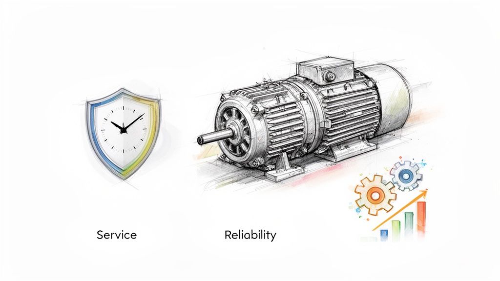
When you hear "electric motor service," what comes to mind? For many, it's the frantic call you make after a critical motor grinds to a halt. But that’s a reactive, costly way to operate.
True electric motor service is about proactive management—a strategic blend of inspections, diagnostics, and smart maintenance designed to keep your motors running at peak performance and prevent failures before they ever happen. It’s the difference between managing a predictable asset and getting blindsided by a production-killing crisis.
Your Best Defense Against Downtime Is Proactive Motor Service
Let’s be honest: unplanned downtime is the biggest threat to your bottom line. When a key motor fails, the ripple effect is immediate and expensive, shutting down an entire line and putting production targets in jeopardy. Seeing electric motors service as just a repair function is a massive, and all-too-common, blind spot.
Think of it more like the rigorous maintenance schedule for a high-performance engine. You don't wait for it to break down on the highway. A smart service strategy isn't about just fixing things; it’s about building a powerful, proactive defense that keeps your operation humming. This requires a calculated mix of preventive care, predictive diagnostics, and rapid, effective repairs when they’re absolutely necessary.
The Core Pillars of Effective Motor Management
To build this defense, you need a plan that looks beyond just the motor itself. A truly effective strategy integrates the mechanical health of your motors with the intelligence of their control systems, giving you a complete, 360-degree view of how your assets are performing.
This holistic approach delivers tangible results you can see and measure:
Slash Unplanned Downtime: Catching issues before they escalate means you schedule maintenance on your time, not in the middle of a production emergency.
Extend Equipment Lifespan: Proper care, from lubrication to alignment, can dramatically extend the life of your motors and maximize your capital investment.
Boost Operational Safety: A well-maintained motor is a safe motor. Proactive service helps you spot and fix potential electrical hazards before they can cause an accident.
Lower Your Total Cost of Ownership: Fewer emergency repairs and more energy-efficient operation translate directly to lower long-term costs. A great starting point is building out a solid schedule, and you can find helpful resources like a preventive maintenance schedule template to get started.
A Growing Market Proves Reliability is King
The global demand for reliable motors is exploding. The market is set to jump from USD 212.96 billion in 2025 to a massive USD 405.67 billion by 2033, fueled by a powerful 8.5% annual growth rate.
This isn't just a number; it's a clear signal that operational reliability is more critical than ever. It also highlights the incredible value of having an experienced partner in your corner, like E & I Sales, who has been a trusted electric motor distributor and system integrator since 1974.
By ditching the "fix-it-when-it-breaks" mindset for a proactive service strategy, you turn your maintenance department from a cost center into a powerful competitive advantage that drives reliability and protects your bottom line.
Decoding Motor Health with Key Diagnostic Checkpoints
Trying to understand what’s happening inside an industrial motor with just a visual inspection is like trying to diagnose a patient from across the room. You need to get closer and use the right tools. That's where key diagnostic checkpoints come in—they act as an early warning system, translating subtle signals from your equipment into hard, actionable data.
This isn't about guesswork. It's about shifting your maintenance strategy from a reactive firefight to a proactive, scheduled process that catches problems before they become catastrophic failures. Each test gives you a different piece of the puzzle, building a complete picture of your motor's health so you can make smart decisions.
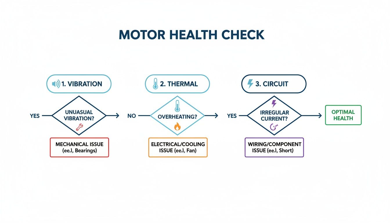
Vibration Analysis: The Stethoscope for Your Machinery
Just like a doctor listens to a patient’s heartbeat with a stethoscope, our technicians use vibration analysis to listen to the mechanical "hum" of your motors. Every single rotating part—from the shaft and bearings to the cooling fan—creates its own unique vibration signature when it's running smoothly.
The moment a component starts to wear out, fall out of alignment, or become imbalanced, that signature changes. These tiny shifts are often detectable long before you could ever hear or see a problem. A skilled technician can read these vibration patterns to pinpoint the exact source of a developing issue, whether it’s a minor imbalance or the very first signs of bearing fatigue. In fact, predictive maintenance programs driven by this kind of data have been shown to slash equipment breakdowns by up to 70%.
Think about it: you can schedule a quick, minor fix like rebalancing a rotor on your own terms, instead of being forced into a massive, production-halting motor rebuild in the middle of a critical run.
Thermal Imaging: Spotting Hidden Hotspots
Heat is the silent killer of electric motors. When things get too hot, insulation starts to degrade, lubrication breaks down, and every component begins to wear out faster. Thermal imaging, or thermography, lets us see what the naked eye can't by creating a visual map of heat signatures.
A quick thermal scan can immediately flag problems that would otherwise go unnoticed:
Overloaded Circuits: A high-resistance connection in the terminal box will glow like a beacon.
Failing Bearings: As a bearing starts to fail, the increased friction generates a ton of heat.
Blocked Ventilation: Clogged cooling fins or a dead fan will cause the entire motor casing to overheat.
Catching these thermal anomalies early means you can address the root cause—like tightening a loose wire or just cleaning out a vent—before it snowballs into a serious electrical or mechanical failure. This is also a massive safety issue. Staying on top of motor health isn't just about uptime; it's about protecting your team. Anyone responsible for workplace safety should Master NFPA 70E Electrical Safety Guidance to keep everyone safe.
Motor Circuit Analysis: A Window into Winding Health
While vibration and thermal checks give us a great look at the mechanical and heat-related stresses, Motor Circuit Analysis (MCA) goes a level deeper into the motor's electrical integrity. This powerful diagnostic sends a series of low-voltage signals through the windings to measure critical electrical properties like resistance, inductance, and how well the insulation is holding up.
MCA is fantastic at finding those tricky, hard-to-detect issues that other tests might miss entirely. It can spot the very beginning of insulation breakdown between winding turns, a slowly deteriorating connection, or even contamination from dust and moisture. We dive deeper into these concepts in our article on the protection of motors.
This electrical assessment gives you a clear, definitive baseline of your motor's condition. From there, you can track any degradation over time and make an informed call on scheduling a rewind or replacement long before an electrical fault shuts down your line without warning.
Making The Critical Decision: Repair Or Replace Your Motor?
When a critical motor goes down, your whole line grinds to a halt. Suddenly, you're on the clock, facing a high-stakes decision under a ton of pressure: do you repair the failing motor or spring for a brand-new replacement? This is way more than just comparing two price tags. It's a complex operational and financial choice that will echo in your budget and productivity reports for years.
The smart play here is to look past the immediate repair quote. You need to think in terms of Total Cost of Ownership (TCO). This framework forces you to balance the upfront cash outlay against the long-term realities—things like energy consumption, the odds of another failure, and the pure lead time to get your line humming again. A cheap, quick fix might seem like a win today, but it could end up costing you a fortune down the road.
Evaluating Key Decision Factors
Every motor failure is its own little drama, but a structured approach helps you take the emotion out of it. Picture a scale. On one side, you've got the immediate cost and speed of a repair. On the other, you have the long-term efficiency, rock-solid reliability, and warranty that come with a new motor.
The motor's age is a huge piece of the puzzle. An older, standard-efficiency motor that’s been rewound a few times isn't the same machine it was. Each rewind can chip away at its efficiency, which means your energy bills creep up over its remaining life.
On the flip side, a modern NEMA Premium efficiency motor could deliver some serious energy savings, often paying for itself over time. How critical is the application? That's another big question. For a motor on a piece of non-essential equipment, a repair might be perfectly logical. But for the motor that’s the heart and soul of your main production line? The peace of mind from a new, reliable unit often makes the higher upfront cost a no-brainer.
A quick health check using a few key diagnostics can give you the hard data you need to make a smarter call. This flowchart breaks down a simple 3-step process for getting a real feel for your motor's condition.
As you can see, checking vibration, thermal signatures, and circuit integrity paints a complete picture. It helps you see if a simple fix will do the trick or if deeper problems are signaling it's time for a replacement.
Repair vs. Replace Decision Matrix
To help you weigh your options practically, we've put together a simple decision matrix. Think of it as a cheat sheet for organizing your thoughts when you're under pressure.
Decision Factor
Favoring Repair
Favoring Replacement
Motor Age
Relatively new (under 5-7 years) with a first-time failure.
Older motor (10+ years), especially if it has been rewound before.
Repair Cost
Less than 50% of the cost of a new, comparable motor.
Repair quote is over 50% of the replacement cost.
Criticality
Non-critical application where downtime is manageable.
Heart of the production line; reliability is non-negotiable.
Energy Efficiency
Motor is already an energy-efficient model.
Current motor is standard efficiency; a new premium model offers major savings.
Lead Time
Repair can be completed much faster than a new motor can be sourced.
A new motor is readily available, and repair time is uncertain.
Warranty
N/A (repairs may have limited warranty on work performed).
Comes with a full manufacturer's warranty for peace of mind.
Looking at these factors side-by-side helps clarify which path offers the best long-term value, not just the quickest fix.
The Real-World ROI of Replacement
Let's walk through a real scenario. A packaging plant was running a 15-year-old, 100 HP motor on its main conveyor. After a bearing failure, they got a quote for $7,000 for a full rebuild. Not bad, right? But a brand-new, premium-efficiency motor was $12,000. While the repair was cheaper upfront, someone did the math. The old motor was sucking down an extra $4,500 a year in electricity compared to the new model.
By choosing to replace it, the plant hit its payback in just over a year on energy savings alone. Plus, they got a new warranty and wiped out the risk of another age-related failure popping up next quarter. This kind of data-driven thinking turns a simple maintenance headache into a strategic investment. To get these calculations right, you need a solid grasp of motor performance; our guide on torque calculation for motor is a great place to start.
Weighing The Strategic Variables
Let's face it, the industrial world runs on AC electric motors, especially those over 1 hp. They're the backbone of just about every automated process. Getting your service strategy right can extend the life of these critical assets by as much as 50% and slash energy use by 10-20%. The repair-or-replace decision is right at the center of capturing those gains.
The decision to repair or replace isn't just a technical choice—it's a business strategy. By evaluating total cost of ownership, application criticality, and long-term energy savings, you can make a data-backed decision that boosts reliability and improves your bottom line.
At the end of the day, the goal is to make a choice that delivers operational stability and financial health. A great rule of thumb we've used for years is the "50% rule": if the repair costs more than half the price of a new replacement, it's almost always smarter to replace it. Combine that guideline with a clear-eyed look at your specific situation, and you can navigate this critical decision with confidence.
Choosing the Right Service Partner
Picking a partner for your electric motors service is a huge deal. Get it right, and you’ve got an extension of your own team—an expert who sees trouble coming and keeps your plant running smoothly. Get it wrong, and you're just paying someone to fix what’s broken, trapping you in a never-ending cycle of putting out fires.
This isn’t about finding the lowest price. It's about finding a team that gets the whole picture, from the motor spinning on the floor to the complex controls making it happen. Their real value lies in their technical chops, how fast they respond, and their mindset. That's what separates a simple vendor from a true strategic partner.
The Technical Non-Negotiables
Before you even think about anything else, a potential partner has to clear a few technical hurdles. These are the absolute basics, the proof that they can handle modern industrial equipment safely and correctly.
Your checklist should start here:
Proven Field Service Expertise: Can they get a qualified tech to your site, pronto? Whether it’s for troubleshooting, a new install, or commissioning, on-site support is everything when a line goes down.
UL 508A Panel Shop Certification: This one’s a biggie. A UL 508A certification is your proof that they build control panels to the highest industry standards for safety and reliability. It’s not just a nice-to-have; it’s a mark of quality.
Deep Industry Experience: Do they speak your language? A partner who’s worked in packaging, food and beverage, or your specific manufacturing world will understand your operational headaches and get to the right solution much faster.
Think of these as your first filter. If a provider can't check these boxes, they don't have the foundational skills you need.
Beyond the Spec Sheet: The Traits of a True Partner
Once you’ve confirmed the technical skills are there, the real evaluation can begin. The best service partners bring a lot more to the table than what you’ll find on a line card. These are the qualities that make for a solid, long-term relationship.
You’re looking for a provider who shows:
Responsive Communication: When you're facing downtime, you need answers, not voicemails. A partner who picks up the phone and gives you clear, honest updates is worth their weight in gold during a crisis.
A Genuine Problem-Solving Mindset: Do they just slap a band-aid on the issue, or do they dig in to find out why it happened? A great partner is obsessed with finding the root cause to make sure it doesn't happen again.
A true single-source partner doesn't just supply a motor or build a panel. They take ownership of the entire system, from initial specification and design to seamless integration and startup, dramatically reducing project complexity and helping you get operational faster.
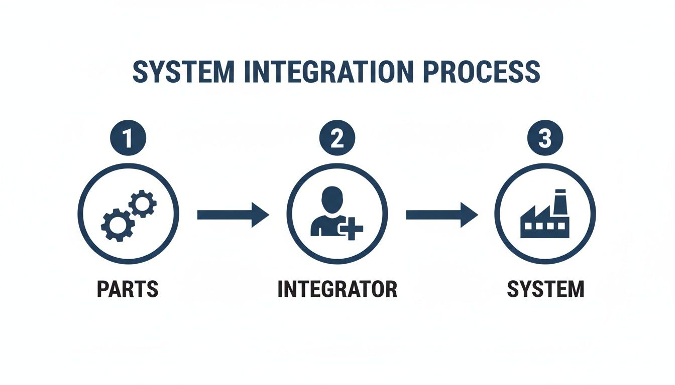
The Power of a Single-Source Integrator
Trying to manage separate vendors for motors, control panels, and on-site integration is a classic recipe for disaster. It’s a mess of missed deadlines, crossed wires, and blown budgets. And when something inevitably goes wrong, the finger-pointing starts, with you stuck right in the middle.
A single-source partner cuts through all that chaos.
By handling everything from motor selection to panel design and final commissioning, they give you one point of contact and one team that’s accountable for the entire project. This integrated approach ensures that every single component is designed from the get-go to work together perfectly.
This is especially powerful for OEMs and plant engineers looking to standardize their equipment. A good integrator can help you build repeatable, rock-solid solutions that make maintenance easier, slash your spare parts inventory, and deliver consistent performance across every line. At the end of the day, choosing an electric motors service provider is about finding a partner who is as invested in your success as you are.
Integrating Motor Service with Controls and Automation
An industrial motor is never a solo act. It’s the powerhouse at the heart of a much bigger system, taking its cues from a whole network of controls, drives, and automation logic. That’s precisely why modern electric motors service has to look beyond the motor itself and see the entire ecosystem.
Fixing a motor in a vacuum is like a mechanic tuning an engine without ever plugging into the car's computer. You might fix one problem but miss the root cause entirely. The real reliability—the kind you can count on—comes when the motor and its controls are working in perfect harmony.
Think about it: a Variable Frequency Drive (VFD) could be sending out flawless power, but if the motor's overload settings aren't dialed in correctly on the PLC, you're just one jam-up away from a catastrophic burnout. A true system integrator lives and breathes this delicate balance, making sure every piece of the puzzle is set up to protect the others.
The Critical Role of UL-Listed Control Panels
Right in the middle of all this sits the control panel. This is command central, the box that houses the motor starters, VFDs, and PLCs that make the whole operation intelligent. For any serious industrial setup, specifying a custom UL-listed control panel isn't just a good idea—it's non-negotiable.
That UL mark is so much more than a sticker. It's your guarantee that the panel was designed and built to meet the industry's highest safety and quality standards. It certifies that every single component, from the wiring gauge to the circuit breakers, was chosen, installed, and tested to perform safely under real-world industrial loads.
A service partner with an in-house UL 508A panel shop brings a ton of value to the table:
Ensuring Compliance: They build panels that satisfy strict national safety codes, which is step one in protecting your people and your plant.
Designing for the Application: They can build a panel perfectly tailored to your motor and process, instead of trying to shoehorn an off-the-shelf box into a job it wasn't made for.
Streamlining Integration: When the same team that understands your motor also designs and builds its controls, you eliminate those frustrating compatibility headaches from the start.
Weaving Diagnostics into Your Automation System
The most sophisticated operations take this a step further. They don't just protect their motors; they actually listen to them. Today's VFDs and smart relays are packed with incredibly valuable diagnostic data, tracking everything from current draw and operating temperature to torque load.
A skilled integrator can tap into this stream of data and feed it directly into your plant's main automation platform, like a SCADA or HMI. Suddenly, your control room becomes a central hub for motor health monitoring. Instead of waiting for a maintenance tech to walk the floor and take a reading, your operators can spot a potential overload or an overheating trend in real-time, right on their screen.
Partnering with an expert in both motors and controls creates a unified system where every component works together. This holistic approach leads to safer, more reliable, and far more efficient industrial operations.
This push for deeper integration is all about the relentless pursuit of efficiency. The global electric motor market, valued at USD 152.2 billion in 2024, is expected to hit USD 206.4 billion by 2029. A massive part of that growth is the switch to high-efficiency motors, which can slash energy consumption by 20-40%. Turnkey services that standardize motor control centers (MCCs) and switchgear are essential, often cutting commissioning time by weeks and dramatically reducing downtime risks. You can explore more about these market trends and their impact on industrial applications to get the full picture.
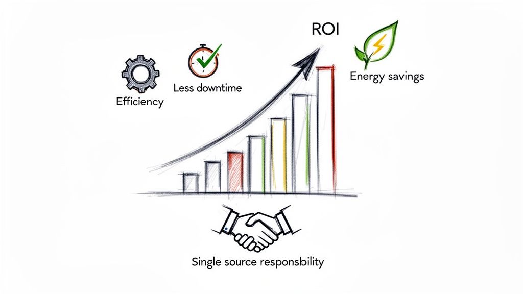
Maximizing Your ROI with a Strategic Service Plan
It's easy to look at electric motors service as just another line item on the expense sheet. But that’s an outdated, and frankly, expensive way of thinking.
Let’s reframe this. A strategic service plan isn't a cost center. It's a powerful profit driver that aggressively protects your most valuable asset: uptime. This isn't about reactive firefights anymore; it's a calculated business strategy that delivers a real, measurable return on your investment (ROI).
Every decision—from running proactive diagnostics to planning a system-wide integration—feeds directly back to your bottom line. Think of it like a flywheel. Each smart service action builds momentum, creating benefits that compound across your entire operation. Working with the right service partner unlocks this value, turning motor management into a genuine competitive advantage.
Translating Service into Financial Wins
So, where does this ROI actually show up? It’s not some abstract concept; you’ll see it in clear, undeniable ways on your financial statements. It's cash you save and production you gain.
A well-executed plan directly chips away at operational costs while boosting your output. Here’s where you’ll see the return:
Drastically Lower Energy Bills: Modern, well-maintained motors are just plain thriftier on power. Simply replacing or properly servicing an older motor can slash its energy use by 10-20%. Those savings add up every single hour it’s running.
Reduced Unplanned Downtime: This is the big one. Predictive maintenance catches failures before they happen, letting you schedule repairs on your terms. Moving from emergency response to planned action can save you thousands in lost production and frantic overtime costs.
Longer Asset Life: Simple, proactive care like proper lubrication and alignment can extend a motor's working life by as much as 50%. You get more out of your initial capital investment and push those big replacement costs further down the road.
A well-oiled service strategy isn't just about the maintenance department—it creates a cascade of positive outcomes for everyone involved in the production lifecycle. It smooths out processes, removes bottlenecks, and empowers your teams to hit their goals with more confidence and far fewer surprises.
Embracing a proactive electric motors service plan is the cornerstone of operational excellence. It is a fundamental shift that empowers your entire team to move from merely fixing problems to actively preventing them, driving reliability and profitability.
Just think about how the benefits ripple out:
For OEMs and Packagers: When you have standardized, reliable motor and control solutions, projects get done faster. Your final product is higher quality, and you get to market quicker.
For Plant Managers: Consistent uptime and predictable maintenance schedules make it infinitely easier to meet—and even beat—those demanding production quotas.
For Maintenance Teams: With fewer emergencies blowing up their day, technicians can finally focus on high-value preventive work instead of constantly putting out fires.
Ultimately, it’s time to stop thinking about service and start thinking about strategy. Partner with an expert who gets the entire system—from the motor to its controls—and unlock the immense value just waiting to be tapped in your facility.
A Few Common Questions About Electric Motor Service
Even the most experienced plant managers and engineers have questions when it comes to fine-tuning their electric motor service strategy. Let's tackle a few of the most common ones we hear out in the field.
Getting the right answers here can help you sharpen your maintenance plan, sidestep common failures, and make sure you're getting real value from your service partner.
What Is the Most Common Cause of Industrial Motor Failure?
Bearings. Hands down. Bearing issues are the undisputed champ of motor failure, causing over 50% of all breakdowns. The thing is, this isn't just a string of bad luck—it's almost always preventable.
So what's taking them out? It usually comes down to one of these culprits:
Improper Lubrication: This is a big one. Using the wrong grease, adding too much, or not adding enough is a surefire way to kill a bearing.
Contamination: When dirt, dust, or moisture find their way into the bearing housing, they act like sandpaper, creating friction that destroys precision surfaces.
Shaft Misalignment: If the motor shaft isn't perfectly aligned with the load, it puts incredible stress on the bearings, forcing them to wear out long before their time.
Excessive Vibration: An unbalanced rotor or some other mechanical gremlin sends damaging vibrations right through the shaft and into the bearings.
Your best line of defense is a proactive service plan. Making regular lubrication and vibration analysis a non-negotiable part of your routine is the key to stopping these killers in their tracks.
How Often Should My Critical Motors Be Serviced?
There's no magic number here. The right service interval really depends on the motor's job, its working environment, and how critical it is to your operation.
Think of it in tiers:
High-Priority Motors: For the workhorses running 24/7 in hot, dirty, or demanding conditions, getting them checked out quarterly is a smart move.
Standard-Duty Motors: For motors in cleaner, more controlled settings that aren't quite as critical, an annual service and inspection is often plenty.
The best approach? Work with an experienced service provider to walk your floor. They can help you build a custom maintenance schedule that makes sense for your plant's specific equipment and production needs.
Just guessing at maintenance intervals is a recipe for disaster. You either end up wasting money on service you don't need or facing a surprise breakdown you can't afford. A schedule based on real-world conditions ensures you're servicing the right motor at the right time.
Can a Variable Frequency Drive Damage a Motor?
Absolutely. A VFD can definitely cause serious damage, but only if it's installed or configured incorrectly, or if it's a poor match for the motor itself. The two biggest problems we see are bearing damage from stray electrical currents (a phenomenon called fluting) and winding insulation breakdown caused by sharp voltage spikes from the drive.
This is exactly why a holistic approach to electric motors service is so critical. A good partner doesn't just sell you a VFD. They make sure the entire system—the motor, the drive, and the cabling—is engineered to work together flawlessly. That's how you protect your investment and get the performance and efficiency you're paying for.
Ready to build a service strategy that drives reliability instead of just reacting to failures? The experts at E & I Sales design, build, and support integrated motor and control solutions that prevent downtime and maximize performance. Contact us today to optimize your operations.
Think of them as the master architect and general contractor for your factory's automation systems, all rolled into one. You’ve got all the best-in-class components—motors from one supplier, drives from another, sensors, PLCs, and sophisticated software. On their own, they're just a pile of expensive parts. The system integrator is the expert team that makes them all talk to each other and work in perfect harmony.
They are the ones who transform a collection of individual pieces of equipment into a single, reliable, and efficient operational powerhouse.
What Does a System Integrator Actually Do?
Let's stick with an analogy. Imagine you're building a custom race car. You've sourced a high-performance engine from Germany, a cutting-edge transmission from Japan, and a complex electronics package from the U.S. They're all top-of-the-line, but they won't work together out of the box.
The system integrator is the specialized engineering crew that designs the custom mounts, writes the control software, and wires everything together. They ensure the engine's raw power is smoothly and reliably translated to the wheels. Without them, you just have a very expensive garage ornament.
In an industrial setting, this role is absolutely critical. An SI bridges the gap between the physical machinery on the plant floor and the software that controls it. They don't just plug in a few cables; they design and build the entire "nervous system" of an operation. This complex job includes everything from programming controllers to fabricating UL-listed electrical panels that safely manage and distribute power.
At its core, the system integrator’s job is to make different, often competing, systems communicate and cooperate seamlessly. They are the specialists who design, build, and implement custom solutions that get your hardware, software, and networks playing nicely together. The fact that the global system integrator market has exploded into a massive industry really speaks to just how essential this function is for modern manufacturing and production.
This concept isn't limited to the factory floor, either. In the business world, a common SI task is connecting a company's customer relationship management (CRM) software with its other business applications. This kind of project ensures that sales data, customer support tickets, and marketing campaigns are all perfectly synchronized. While it's an IT-focused example, the principle is identical: making separate systems work as one cohesive unit. For those interested in that side of things, it's worth understanding CRM integration and app syncing.
Ultimately, whether it's for motors and drives or software and databases, an SI ensures your entire operation runs like a single, intelligent entity.
To put it simply, here’s a quick rundown of their main responsibilities.
System Integrator Core Functions at a Glance
This table breaks down the primary roles of a system integrator, offering a snapshot of their key contributions to any industrial automation project.
Core Function
Description
Example Application
System Design
Creating the complete architectural blueprint for how all hardware and software components will connect and interact.
Designing a control system schematic for a new conveyor line, specifying all PLCs, VFDs, and sensors.
Programming
Writing and testing the custom code that governs the logic and behavior of the automated system (PLCs, HMIs).
Developing the PLC logic that starts and stops motors in a specific sequence based on sensor inputs.
Panel Integration
Building, wiring, and testing the UL-listed electrical control panels that house all the control hardware.
Assembling a NEMA-rated panel with motor starters, circuit breakers, and a PLC for a pump station.
Commissioning
On-site testing and fine-tuning of the entire system to ensure it operates correctly and meets performance specs.
Calibrating motor drive parameters and testing emergency stop functions on the factory floor before going live.
Documentation
Providing comprehensive schematics, user manuals, and maintenance guides for the completed system.
Creating a complete set of electrical drawings and a troubleshooting guide for the maintenance team.
Compliance
Ensuring the system adheres to all relevant safety standards, codes, and regulations (e.g., UL 508A, NFPA 79).
Verifying that all panel wiring and component spacing meet UL standards for certification.
From initial design to final sign-off, a system integrator manages the entire lifecycle of an automation project, making sure every piece fits and functions as intended.
The Critical Roles a System Integrator Plays
So, what does a system integrator actually do? Beyond just connecting a few wires, their real value comes from the specific, hands-on jobs they manage from the first sketch to the final handshake. They're the technical specialists who take a concept on a whiteboard and turn it into a humming, reliable piece of your industrial process.
It’s a step-by-step mission, with each role building on the one before it.
Design and Engineering
Everything starts with a blueprint. The first thing an integrator does is create the detailed electrical schematics and Piping and Instrument Diagrams (P&IDs). Think of this as mapping out the "nervous system" of your automation process. It's where they define how every motor, sensor, and controller will talk to each other.
For instance, when designing a motor control center, they're not just picking parts off a shelf. They’re specifying every single component, from the variable frequency drives (VFDs) down to the circuit breakers, making absolutely sure the design is safe, efficient, and meets all electrical codes. This upfront engineering is what prevents hugely expensive mistakes down the road.
Programming and Panel Fabrication
With a solid design locked in, the integrator’s team shifts gears. One part of the team starts programming the brains of the operation—the Programmable Logic Controllers (PLCs). This is where custom code is written to run the automation sequences. They also build the intuitive screens for Human-Machine Interfaces (HMIs) and set up the Supervisory Control and Data Acquisition (SCADA) systems that give you a bird's-eye view of the whole plant.
At the same time, their shop technicians are busy with the physical build. This is where the control system really comes to life. They assemble and wire the UL-listed control panels, which are the custom-built enclosures that safely house all the automation gear. In our world, this hands-on hardware integration is a massive part of the job, bridging the gap between a pile of components and a true turnkey solution. A well-integrated system can cut project timelines by 25% and slash downtime by 20%—that's the kind of value we're talking about.
Commissioning and Documentation
Once the panels are built and the code is written, the integrator packs up and heads to the job site for commissioning. This is where the rubber meets the road. The integrator connects everything on-site, powers up the system, and starts the intense testing process. They’re checking that every motor spins up correctly, every sensor is reading accurately, and all safety circuits work exactly as designed.
Often, they’ll run a Factory Acceptance Test (FAT) at their own shop before the gear ever ships. To get a feel for how detailed this gets, you can check out our comprehensive factory acceptance test checklist. A huge part of an integrator's job is managing these complex installations to make sure everything plays nicely together. For more on that, you can find some great enterprise application integration best practices here.
This simple flow shows how an integrator pulls all the individual pieces together into one cohesive system.
As you can see, the integrator is that critical link in the middle, adding the intelligence and assembly needed to turn a box of parts into a working solution.
Finally, they hand over the keys—the complete documentation package. This isn't just a few papers; it includes the as-built electrical drawings, all the program code, operational manuals, and a detailed bill of materials. This binder is your maintenance team's bible, giving them everything they need to troubleshoot and maintain the system for years to come.
Understanding Your Industrial Project Team
On any large industrial project, you’ll find a whole cast of specialists working together. But let's be honest, their roles can get a little blurry. Knowing who does what is absolutely critical to getting the job done right.
To really get a handle on what a system integrator is, it helps to see how they fit in with the other key players you'll find on site, like EPC firms, OEMs, and electrical contractors. Each one owns a distinct piece of the project puzzle. Getting it wrong—like calling a general contractor to program a complex assembly line—can lead to costly delays and a whole lot of frustration.
Distinguishing Key Project Roles
Let’s use an analogy. Imagine you're building a brand new hospital from the ground up.
The Engineering, Procurement, and Construction (EPC) firm is your master developer. They’re looking at the big picture, handling everything from acquiring the land and designing the building to procuring the big-ticket items like MRI machines and HVAC systems. They manage the entire construction process and hand over the keys to a finished hospital.
An Original Equipment Manufacturer (OEM) is the company that actually builds that specialized equipment. They're the experts who engineer and manufacture the high-tech MRI machine or the high-efficiency air handler. Their world revolves around perfecting their product and delivering it as a rock-solid, standalone piece of hardware.
So, where does the system integrator (SI) come in? The SI is the specialist team that brings the hospital’s "central nervous system" to life. They don't pour the concrete or build the MRI machine, but they make that MRI machine talk to the patient record system. They connect the HVAC controls to the building automation software and make sure every critical alarm and data point flows seamlessly to the central nurses' station. Their sole focus is making a bunch of different technologies work together as one smart, cohesive system.
And finally, you have the electrical contractor. These are the skilled tradespeople who physically pull the wire and terminate the connections based on the engineered drawings from the SI or EPC. They're the ones in the trenches installing conduit, landing wires in control panels, and ensuring every physical connection is safe, secure, and up to code.
Key Takeaway: An EPC builds the whole facility. An OEM builds a specific machine. An electrical contractor runs the wires. A system integrator makes all the different machines and software systems talk to each other and work as one.
Comparing Industrial Project Roles
To clear things up even further, this table breaks down the distinct responsibilities of each team. It’s a quick guide to help you figure out who you really need to call for your specific job.
Role
Primary Focus
Typical Scope
Key Deliverable
System Integrator
Making separate automation, control, and software components work together as a single, functional system.
Design, programming, panel fabrication, and commissioning of control systems.
A fully tested and documented, integrated automation solution (e.g., a UL-listed control panel and its programming).
EPC Firm
Managing the entire project lifecycle from concept to completion, covering all disciplines (civil, mechanical, electrical).
Full facility design, procurement of all major equipment, and overall construction management.
A complete, turnkey operational facility or plant.
OEM
Designing and manufacturing a specific piece of machinery or equipment for a specialized function.
The engineering and fabrication of their proprietary equipment.
A standalone, functional piece of equipment (e.g., a pump skid, a CNC machine, a conveyor).
Electrical Contractor
The physical installation, termination, and testing of electrical wiring, conduit, and components.
Running power lines, connecting motors, and wiring panels according to engineered schematics.
A safely installed and code-compliant electrical installation.
While their jobs are different, great projects happen when all these teams communicate and work together smoothly. Understanding who to bring in, and when, is the first step toward a successful outcome.
Real-World Benefits of a System Integrator Partnership
Let's get past the technical jargon for a minute. The decision to bring in a system integrator really boils down to business results. The true return on your investment isn't just in the new panel or the lines of code—it’s in the measurable kick to your bottom line. An expert SI adds value by cutting downtime, boosting efficiency, and getting your project across the finish line faster.
Think about a manufacturing plant constantly dealing with shutdowns because of old, mismatched motor controls. An integrator comes in, designs a modern and unified system, and suddenly things just work. This isn't just about better reliability; it's about real performance gains, like a 20% drop in energy costs and far fewer calls to maintenance.
The real magic is having a single source of responsibility who owns the outcome. It puts an end to the frustrating "blame game" that always seems to pop up between different vendors when something goes wrong.
Driving Efficiency and Slashing Downtime
One of the first things you'll notice after hiring a good SI is a sharp jump in how efficiently your plant runs. When all your components—from the drives to the PLCs—are communicating perfectly, you eliminate the bottlenecks that were secretly killing your productivity. This optimization leads directly to more product out the door and lower costs to make it.
For instance, you might have a heavy-duty conveyor from one OEM and a high-tech packaging machine from another. An integrator is the one who makes them work in sync, like a single, well-oiled machine instead of two separate, clunky steps. That’s the kind of cohesion that stops all those small, recurring delays from eating away at your profits.
A skilled system integrator doesn't just connect boxes; they find hidden efficiencies. By looking at the entire operation, they spot opportunities for improvement that individual equipment vendors would never see, leading to faster cycles and less waste.
The Value of a Single Point of Contact
When you’ve got multiple vendors on a project, figuring out who’s responsible for a problem can be a complete nightmare. Is it a bad sensor, or is it the PLC program? Did the motor starter get sized wrong, or did the electrical contractor miswire something?
A system integrator takes full ownership of the control system. Period. This single point of accountability makes managing the project incredibly simple and ensures you get a cohesive, high-performing result. They're the glue in modern industry, bringing motor control, automation, and power systems together into unified, UL-listed packages that slash inefficiencies. For automation specialists, this means turnkey solutions that can cut commissioning time by 35% while keeping everything up to code. You can learn more about how this single-source approach reduces project risks.
This all-in-one approach gives you a few key advantages:
Accelerated Timelines: With one team managing everything, coordination is seamless and projects get done faster.
Guaranteed Compatibility: The SI makes sure every single component is chosen and programmed to work together without a hitch.
Simplified Support: When you need help, you’ve got one number to call for the entire system. No more runaround.
At the end of the day, partnering with a system integrator is an investment in certainty, efficiency, and a whole lot of peace of mind.
Key Signs That You Need a System Integrator
Knowing when to bring in a specialist can be the difference between a smooth project and one that completely derails. Certain pain points and project milestones are red flags, clear signals that you've hit the limits of what you can handle in-house. Recognizing these signs early helps you get ahead of the problem before it snowballs.
One of the most common triggers is a major facility expansion or a totally new greenfield project. As you scale up, the complexity of your control systems doesn't just add up—it multiplies. An SI provides the crucial big-picture engineering to make sure all your new and existing systems actually talk to each other from day one, helping you avoid the costly, patched-together fixes that so often plague large-scale builds.
When Your Technology Is Working Against You
Another dead giveaway is when you're fighting with unreliable, outdated legacy controls. If your team is constantly putting out fires—troubleshooting random shutdowns or hunting for obsolete parts that just don't exist anymore—it’s a massive drain on your productivity. A system integrator lives and breathes this stuff; they specialize in modernizing these fragile, aging systems into a robust, unified platform that not only works reliably but also gives you valuable data about your operations.
Think about where your equipment comes from, too. If your project involves machinery from a handful of different manufacturers, you’re walking right into a classic integration nightmare. Each OEM delivers a machine that runs beautifully on its own, but getting them all to communicate and operate in a perfectly synchronized sequence? That’s a whole different ballgame.
This is exactly where a system integrator becomes mission-critical. They’re the independent experts who speak the "language" of all the different control platforms, ensuring a machine from Germany plays nice with one from Japan and another from right here in the U.S.
Filling Critical Gaps in Your Team
Sometimes, the need for an SI boils down to your own team's bandwidth and expertise. You might have a fantastic maintenance crew and sharp engineers, but they probably aren’t deep in the weeds of complex PLC programming or designing and building certified control panels every day. A system integrator brings that specialized, niche knowledge to your project without the overhead of hiring a full-time specialist.
Here are a few more tell-tale signs it’s time to pick up the phone:
You Require UL 508A Certified Panels: If your project specs or local inspectors demand UL-certified control panels for safety and compliance, an integrator with a UL 508A panel shop is non-negotiable. There's no way around it.
You Lack Comprehensive Documentation: Are your electrical drawings missing, or so old they look like ancient scrolls? An SI can reverse-engineer your setup and create the accurate documentation you absolutely need for safe and efficient maintenance.
You're Facing Unexplained Inefficiencies: When production is lagging but you can’t figure out why, you've got a bottleneck. An integrator can analyze your entire process, diagnose the weak points, and show you where smarter automation can boost performance.
If any of these scenarios hit a little too close to home, your operation has likely outgrown the do-it-yourself approach. An integrator’s expertise quickly shifts from a "nice-to-have" to a necessity for hitting your production goals safely and efficiently.
How to Choose the Right System Integrator
Picking the right system integrator is easily one of the biggest calls you'll make for your project. Get it right, and you're set up for success. Get it wrong, and you're in for a world of headaches. While technical chops are the price of entry, the best partners bring direct, relevant experience to your facility floor.
Think about it this way: not all integrators are cut from the same cloth. The team that excels at sprawling oil and gas facilities might not be the best fit for the nuanced, high-speed demands of a food and beverage line.
Your first move should always be to screen for industry-specific expertise. An integrator who already speaks your language—understanding the regulations, the operational quirks, and the common pitfalls of your sector—is invaluable. They’ll design a more practical and compliant solution from day one, which saves you from costly do-overs down the road.
Key Evaluation Criteria
Beyond their resume, you need to look for hard proof of their qualifications and a solid track record. The right partner won't just tell you they're good; they'll show you.
Technical Certifications: First question: is their panel shop UL 508A certified? This isn't just a nice-to-have; it's a critical benchmark for quality, proving their panels meet rigorous safety and construction standards.
Platform Expertise: Do they live and breathe the control platforms you rely on, whether it's Rockwell, Siemens, or something else? Deep knowledge of your tech stack means a smoother integration and makes life easier for your maintenance team for years to come.
Documentation Standards: Don't be shy—ask to see a sample documentation package. A good one will be crystal clear and thorough, with detailed schematics, a complete bill of materials, and well-commented code that your team can actually understand.
Crucial Tip: A truly great system integrator won’t just build what you ask for. They'll push back. They’ll ask the tough questions to get to the root of your problem, acting more like a technical consultant who wants to find the best solution, not just the most obvious one.
Questions to Ask Potential Partners
Once you have a shortlist, it's time to talk. These questions can help you figure out who will be the best fit for your team, both technically and culturally.
How do you handle project communication, especially when scope changes happen?
What does your warranty and post-project support look like in the real world?
Can you walk me through a case study for a project that was a lot like this one?
What's your on-site protocol for safety and risk management?
Making the right choice means looking past the price tag and really digging into the team you’ll be partnering with. For a more detailed checklist, our guide on selecting an industrial automation system integrator offers even more tips. A little due diligence here pays massive dividends, ensuring you get a partner who is locked in on your goals.
Your Top Questions About System Integrators, Answered
Even after you're sold on the idea, some practical questions always pop up. It’s one thing to understand the what, but the how is where the rubber meets the road. Let's tackle the most common questions project managers and engineers ask before pulling the trigger on hiring a system integrator.
How Do Integrators Usually Bill for Their Work?
When it comes to pricing, you'll generally see two main flavors. The first is Time and Materials (T&M), where you're paying for the hours spent on engineering and labor, plus the direct cost of all the parts. This model is great when the project scope is a bit fluid and you need the flexibility to adapt as you go.
The other common approach is a Fixed Price contract. Here, you both agree on a very detailed scope of work for one set price. This gives you budget certainty, which is a huge plus. For longer-term needs, some integrators will also offer support contracts on a retainer basis.
Pro Tip: No matter which model you choose, a crystal-clear, meticulously defined scope of work is your best friend. It’s the single most important tool you have to prevent surprise change orders and make sure everyone is on the exact same page about what gets delivered.
Are System Integrators a Good Fit for Small Companies or OEMs?
You bet. In fact, they can be a game-changer. For smaller businesses or Original Equipment Manufacturers (OEMs), bringing on an integrator is like getting access to a world-class engineering team without the hefty price tag and overhead of hiring full-time specialists.
Think about an OEM that builds great machinery. They can partner with an integrator to design, standardize, and build certified UL 508A control panels for their entire product line. This move not only boosts product quality and consistency but also makes their equipment far more marketable by taking complex electrical compliance off their plate. It lets the OEM stick to what they do best—mechanical design—while the integrator handles all the controls.
What Kind of Support Can I Expect After the Project Is Done?
A good system integrator doesn't just pack up their tools and disappear once the system is running. The best ones see the project handover as the start of a partnership, not the end of a transaction. Post-project support should be a standard part of their offering and something you define clearly in the contract.
This support can look like a few different things. It might be a standard warranty period for bug fixes, or it could be a full-blown service level agreement (SLA) that covers everything from 24/7 remote support and preventive maintenance checks to future system upgrades. Always get the details on the level and length of support ironed out before you sign anything.
At E & I Sales, we’re more than just a component supplier; we're your partner in building fully engineered, turnkey solutions. From custom UL-listed control panels to complete system commissioning, we act as the single point of contact to make sure your automation projects get done right. Learn how our integration services can accelerate your next project.
Ever wondered how a massive chemical plant or a sprawling manufacturing facility runs with such clockwork precision? The secret isn't magic—it's process control and instrumentation.
Think of it like the cruise control in your car. You decide you want to go 65 MPH; that's your target, or Setpoint. The car's system constantly reads your actual speed from the speedometer—the Process Variable. If you start going uphill and slow down, the system detects this and automatically gives the engine more gas—the Control Variable—to get you back to 65 MPH. No hands, no feet, just a simple, continuous loop of measuring, comparing, and adjusting.
That same feedback loop is the beating heart of modern industry. From refining oil to bottling beverages, the goal is always to keep critical variables like temperature, pressure, or flow within a tight, optimal range. It’s all about guaranteeing product quality, boosting efficiency, and, most importantly, keeping operations safe.
The Three Core Elements of a Control Loop
Every automated control system, no matter how complex, boils down to three fundamental components. Get these, and you've got the foundation for understanding the entire field.
We can break down these core elements using our cruise control analogy, which makes it easy to see how they apply in a real-world industrial setting.
The Three Core Elements of a Control Loop
Component
Industrial Example
Cruise Control Analogy
Process Variable (PV)
The current temperature inside a furnace.
The actual speed shown on your speedometer.
Setpoint (SP)
The target temperature of 150°C for a chemical reaction.
Your desired speed of 65 MPH.
Control Variable (CV)
The gas valve opening or closing to adjust the furnace's flame.
The throttle adjusting the engine's power.
At the end of the day, a well-designed control loop is all about minimizing the difference—the "error"—between what's actually happening (the PV) and what you want to happen (the SP). This constant, tiny correction is what keeps massive, complex industrial processes stable and predictable.
Why This Matters in the Real World
This isn't just an academic exercise; it's big business. The global process automation and instrumentation market was recently valued between USD 74.45 billion and USD 81.05 billion, with major growth on the horizon. That boom is fueled by a relentless demand for better efficiency, tighter safety protocols, and lower operating costs across every sector imaginable.
Whether it’s getting the mix just right in a pharmaceutical batch or managing precise gas flows for heat treatment, as detailed in this piece on Process Control Heat Treatment Gas Analysis Solutions, the core principles remain the same.
By mastering the relationship between PV, SP, and CV, engineers and technicians can design and maintain the incredibly robust systems that power our world. If you're ready to see the hardware that makes this all possible, our guide to industrial controls and automation is the perfect next step. A solid grasp of these fundamentals is your key to understanding the more advanced strategies and tools that bring modern industry to life.
The Four Pillars of Industrial Instrumentation
Think of an industrial control system like a human nervous system. You have parts that sense the world, parts that send messages, a brain that makes decisions, and muscles that take action. This is the core idea behind all process control and instrumentation—an interconnected network of hardware that keeps things running smoothly.
These components aren't just a random collection of parts; they form a constant, looping conversation. The quality of each piece in that loop has a direct impact on how well the whole system performs. Let's break down the four essential pillars to see how they work together.
Sensors: The Senses of the Process
First up, and arguably the most fundamental, is the sensor. This is the device that's right there in the thick of it, acting as the system's eyes and ears. Its only job is to measure a specific physical property—what we call the Process Variable (PV)—and turn it into a signal the rest of the system can understand, usually an electrical one.
Picture a massive mixing tank in a food plant. A level sensor sitting in the liquid is constantly reporting how full that tank is. In a furnace, a thermocouple is measuring the heat. On a gas pipeline, a pressure sensor is keeping tabs on the force inside. Without good sensors, your control system is flying blind.
Transmitters: The Nerves Sending the Signal
Once the sensor gets a reading, that raw data has to travel to the system’s brain. That's where the transmitter comes in. It takes the tiny, often fragile signal from the sensor, cleans it up, boosts it, and converts it into a standardized signal that can survive a long trip through a noisy industrial plant without getting garbled.
The industry workhorse for this is the 4-20 mA analog signal. In this setup, 4 mA might mean the tank is empty, and 20 mA means it's full. This universal language ensures that a controller from one company can perfectly understand a sensor from another. The transmitter is the critical nerve fiber connecting the senses to the brain.
This concept map shows you exactly how that Process Variable, measured by the sensor and sent by the transmitter, fits into the bigger picture of the control loop.
As you can see, it's a constant cycle: measure, compare, and correct.
Controllers: The Brain Making Decisions
The controller is the central command center of the whole operation. It receives that clean, standardized signal from the transmitter and does the most important job of all: it thinks. It takes the incoming Process Variable (PV) and compares it to the target value—the Setpoint (SP)—that an operator has programmed in.
Based on the difference, or "error," between what is happening and what should be happening, the controller calculates the right move. This "brain" is usually a Programmable Logic Controller (PLC) or a component within a larger Distributed Control System (DCS).
The controller is where all the logic lives. And getting the housing for this brain right is just as important as the logic itself, a topic we cover in our guide to industrial control panel design.
Final Control Elements: The Muscles Taking Action
A decision is worthless if you can't act on it. The last piece of the puzzle is the Final Control Element (FCE), which acts as the muscle of the system. It takes the command from the controller and physically changes something in the process to get that Process Variable back in line with the Setpoint.
This is where the rubber meets the road. The FCE is the part doing the actual work, and it can take many forms:
A control valve that opens or closes a little more to adjust the flow of a liquid.
A heating element in an oven that kicks on to bring the temperature up.
A Variable Frequency Drive (VFD) that speeds up or slows down a motor running a pump.
Put them all together—Sensor, Transmitter, Controller, and Final Control Element—and you have a closed-loop system that is constantly measuring, comparing, deciding, and acting. This simple but powerful architecture is the bedrock of modern industrial automation, making sure processes run safely, efficiently, and with incredible consistency.
Choosing the Right Process Control Strategy
Once your physical hardware is in place, the game shifts from the "what" to the "how." The control strategy is the brain of the operation—it’s the logic your controller uses to hit and hold your target setpoint. Getting this right is what separates a system that constantly fights you from one that runs with clockwork precision.
The undisputed champion in the world of process control and instrumentation is PID control. It’s no exaggeration to call it the workhorse of automation; over 90% of industrial control loops rely on some flavor of it. Its real power comes from its elegant approach to managing a process by looking at the past, present, and future all at once.
PID Control: The Industry Standard
Let's use a simple, everyday task: filling a bathtub. You want the water to hit a specific level at just the right temperature. This familiar chore is a perfect way to understand the three parts of PID (Proportional-Integral-Derivative) control.
Proportional (P): This is your gut reaction. The tub is empty, so you crank the faucet on full blast. As the water level (your Process Variable) gets closer to where you want it (the Setpoint), you start to ease back on the handle. The P-action is a direct response to the current error—the bigger the gap, the bigger the reaction.
Integral (I): This part corrects for stubborn, lingering errors. Maybe your water pressure is a little low, and the tub is filling slower than it should. The I-action remembers this sluggishness and nudges the valve open just a bit more to make up for it, wiping out that small, persistent gap.
Derivative (D): This is all about looking ahead. As the water level surges toward your target, you start turning the faucet off before it gets there. Why? To keep it from overflowing. The D-action looks at how fast things are changing and pumps the brakes to prevent overshooting the target.
By carefully tuning these three elements, a PID controller delivers incredibly stable and reliable command over everything from motor speeds to the temperature inside a chemical reactor.
Advanced Strategies for Complex Challenges
While PID is a fantastic all-rounder, some processes have tricky variables that demand a more sophisticated game plan. For those tougher jobs, engineers bring in strategies like Cascade and Feedforward control for even tighter regulation.
Cascade Control: Manager and Worker Logic
Think about a situation where one variable has a huge, immediate impact on the one you actually care about. A great example is controlling the temperature of a product inside a jacketed reactor. Your main goal is the product temperature (primary variable), but it's directly affected by the jacket temperature (secondary variable).
Cascade control creates a smart "manager-and-worker" setup. The primary controller (the manager) watches the final product temperature. But instead of messing with the steam valve directly, it tells a secondary controller (the worker) what the jacket temperature should be.
This two-loop structure is brilliant at shutting down disturbances before they cause trouble. If steam pressure suddenly fluctuates, the nimble "worker" loop corrects the jacket temperature long before the product temperature even has a chance to drift.
Feedforward Control: Playing Offense Against Disturbances
Feedforward control is all about being proactive, not reactive. It works by spotting a potential disturbance before it hits your process and making a correction ahead of time.
Imagine you’re heating cold liquid as it flows into a tank. If that incoming flow suddenly doubles, a standard feedback controller won't do anything until it sees the tank's overall temperature start to drop.
A feedforward system, on the other hand, is much smarter:
It measures the incoming flow rate (the disturbance).
It instantly calculates how much more steam is needed for that extra liquid.
It opens the steam valve wider at the exact same moment the flow increases.
This anticipatory move slashes the impact of the disturbance, keeping your process remarkably stable. For large-scale systems, understanding these different architectures is critical, a topic we dive into deeper in our breakdown of SCADA vs DCS. Ultimately, choosing the right logic—whether it's the foundational PID or a more advanced strategy—is the key to a responsive, efficient, and reliable control system.
How Control Systems Communicate with Each Other
A control system is only as smart as the information it can share. All the individual sensors, controllers, and actuators we’ve covered don't work alone—they're in a constant, high-speed conversation that keeps an entire facility running in perfect sync. This network is the nervous system of modern process control and instrumentation.
It wasn't always this easy. In the past, every single sensor and valve needed its own dedicated pair of wires running all the way back to a central control panel. Can you imagine the sheer amount of copper required for a plant with thousands of measurement points? It was an absolute beast to install, incredibly expensive, and a complete nightmare to troubleshoot. One bad wire could bring a critical process to a halt, sending technicians on a hunt through massive, identical cable bundles.
Thankfully, we've moved on. Today’s industrial communication is built on rugged, sophisticated digital networks, much like your office internet but designed to withstand the tough environment of a factory floor. These networks have dramatically cut wiring costs, simplified installations, and opened the door to powerful new diagnostic tools.
The Brains of the Operation: PLCs and DCS
At the heart of this communication web, you'll find the main controllers—usually a Programmable Logic Controller (PLC) or a Distributed Control System (DCS). These are the mission control centers, the air traffic controllers directing every signal in the plant.
PLCs are the sprinters, often used to manage individual machines or smaller, lightning-fast processes. They’re masters of discrete logic, like turning a conveyor belt on or off in a split second. A DCS, on the other hand, is the marathon runner, built to manage sprawling, continuous processes across an entire facility. It brings thousands of control loops together into a single, cohesive command center for operators.
Whether it’s a PLC or a DCS, these controllers act as the central hub, gathering data, running the control logic, and sending commands back out to the field. Their ability to speak the right "language" is what makes it all work.
The real magic is in the communication protocols. Think of them as the agreed-upon languages and grammatical rules that let different devices understand one another. Just like humans use English or Spanish, industrial devices use protocols to exchange information clearly and without fail.
Picking the right protocol is a huge decision. It affects everything from system speed and future scalability to how easily you can upgrade your equipment down the road.
Understanding Industrial Communication Protocols
Over the years, a whole zoo of protocols has emerged to solve different industrial challenges. While there are many out there, a few have become the undisputed industry standards because they're reliable, well-supported, and just plain work. Getting a handle on the differences between a workhorse like Modbus and a modern powerhouse like EtherNet/IP is crucial.
A quick look at the major players helps paint the picture. Each protocol was designed with a specific job in mind, and knowing their strengths is key to building a robust network.
Comparing Common Industrial Communication Protocols
Protocol
Primary Use Case
Key Advantage
Modbus
Simple device communication, connecting basic sensors/meters to a PLC.
Extremely simple, universally supported, and easy to implement.
Fieldbus (FOUNDATION, Profibus)
Complex process control, connecting "smart" instruments.
Allows two-way communication and advanced diagnostics over a single pair of wires.
EtherNet/IP
High-speed, plant-wide networking and enterprise integration.
High bandwidth, uses standard Ethernet hardware, and seamlessly connects the factory floor to business systems.
Here's a breakdown of what that means in the real world:
Modbus: Developed way back in 1979, Modbus is the granddaddy of them all. It’s a simple, tough master-slave protocol where one device (the master) asks another (the slave) for its data. It’s not the fastest, but its simplicity makes it a rock-solid choice for basic device connections.
Fieldbus (FOUNDATION Fieldbus & Profibus): These protocols were a massive leap forward. They allowed multiple devices to share the same two wires, but more importantly, they introduced true two-way communication. Suddenly, a smart valve could send back not just its position, but detailed diagnostic data about its own health.
EtherNet/IP: This protocol uses the same technology that powers your office computers and the internet. EtherNet/IP brings incredible speed and bandwidth to the factory floor, allowing control data, diagnostics, and even corporate data to travel on the same network. It's the standard for modern automation for a reason.
These networks provide game-changing benefits. You're looking at drastically less wiring, faster project commissioning, and the power to diagnose a failing sensor from a control room miles away. Whether you're designing a single UL-listed control panel or an entire plant network, a solid grasp of these communication fundamentals is non-negotiable for building a resilient, scalable operation.
Meeting Critical Industry Standards and Compliance
In the world of process control and instrumentation, a clever design is only half the story. For a system to be safe, reliable, and insurable, it absolutely has to play by the rules—and those rules are written in the language of industry standards and codes.
Think of these standards not as suggestions, but as a critical framework. They ensure every component talks to each other correctly, installations won't create hazards, and your entire operation is compliant from day one. Navigating this landscape means getting familiar with a few key players.
You have organizations like the International Society of Automation (ISA), which sets the universal language for things like instrumentation diagrams (P&IDs). Thanks to them, an engineer in Texas and an engineer in Germany can look at the same drawing and know exactly what they’re seeing.
Then there’s the National Electrical Code (NEC), which is all about the hands-on, practical side of the job. It governs the safe installation of all electrical equipment, from how you route a cable to how you ground a panel. Following the NEC isn't just good practice; it's a legal requirement that inspectors enforce to prevent fires and electrical accidents.
The Gold Standard for Control Panels: UL 508A
While the ISA and NEC set the broad stage, the UL 508A certification puts a laser focus on one of the most vital parts of any system: the industrial control panel. This standard from Underwriters Laboratories is the undisputed benchmark for safety and quality in North America.
A UL 508A sticker on a control panel isn't just for show. It’s a declaration that the panel was designed and built to a strict, independently verified set of safety rules. It means every single component inside was chosen, sized, and wired correctly for its specific job.
Partnering with a UL 508A certified panel shop brings some serious, non-negotiable advantages to the table:
Guaranteed Compliance: A UL-listed panel sails through inspections. It's pre-certified to meet national safety standards, which saves a massive amount of time, money, and headaches when the local Authority Having Jurisdiction (AHJ) shows up.
Real-World Safety: The standard is all about the details that prevent disaster—things like proper component spacing to avoid overheating, correct short-circuit current ratings (SCCR), and wiring techniques that protect people from shock and arc flash.
Reduced Liability: If something ever does go wrong, that UL 508A certification is documented proof that you did your due diligence. It shows a clear commitment to safety and is invaluable for any insurance claim or legal review.
Making sure your control panels are built to these standards is a foundational decision. It ensures the "brain" of your system is not just doing its job, but is fundamentally safe, reliable, and built for the long haul. For any serious industrial operation, UL 508A isn't a feature—it's a requirement.
The Future of Industrial Automation Technology
The world of process control and instrumentation is changing, and it's happening fast. We're moving beyond the simple feedback loops that have been the standard for decades and stepping into a new era of smart, predictive, and deeply connected operations. While the core job of measuring and correcting a process isn't going away, the tools we use to do it are becoming incredibly powerful. It’s all about getting industrial facilities ready not just for today, but for whatever comes next.
The engine driving this shift is the Industrial Internet of Things (IIoT). The best way to think about IIoT is that it gives a voice to every single component in your plant—every motor, every valve, every sensor. Instead of just getting a basic 4-20 mA signal, smart instruments can now pour out a ton of diagnostic data over industrial networks. This gives you a level of visibility into the health of your process that was unimaginable just a few years ago.
The Rise of Predictive Maintenance
All this new data unlocks one of the biggest game-changers for modern industry: predictive maintenance. For years, maintenance has been stuck in two inefficient modes. You either fix things after they break (reactive), or you replace parts on a rigid schedule, whether they need it or not (preventative). Both approaches cost you, either in surprise downtime or in wasted parts and labor.
Predictive maintenance flips that script completely. By analyzing live data from IIoT sensors—things like a tiny shift in a motor's vibration or a pump's temperature creeping up by a few degrees—these systems can spot the warning signs of failure weeks or even months out.
This lets your maintenance team switch from a "fail and fix" model to a "predict and prevent" strategy. Instead of getting a frantic call about a catastrophic failure at 3 AM, you can schedule the repair during planned downtime. That's a massive saving in both time and money.
AI and Advanced Process Control
But it’s not just about preventing failures; this new wave of tech is making the processes themselves smarter. Advanced Process Control (APC) systems use artificial intelligence and machine learning to fine-tune operations in ways a standard PID controller just can't match. An APC system can look at hundreds of variables at once, learning the incredibly complex relationships between them to make constant, tiny adjustments.
What does that mean for the bottom line? Huge improvements in:
Yield: Squeezing the maximum amount of high-quality product out of your raw materials.
Energy Efficiency: Cutting down power consumption by running equipment at its absolute sweet spot.
Product Consistency: Tightening up variability to make sure every single batch meets spec perfectly.
This isn't just a niche trend; it's a market-wide shift. The entire process automation market is being reshaped by IIoT and advanced digital tools. Solutions built on predictive maintenance and APC are seeing the fastest growth, signaling that integrators have to move beyond just offering the same old services.
As we look ahead, bringing these technologies into the fold isn't just a simple upgrade—it's a fundamental change in how we think about running an industrial plant. Building systems ready for this connected future is the only way to stay competitive. For a deeper dive, you can learn more about AI enablement in industrial automation and robotics.
Got Questions? We've Got Answers.
When you're deep in the weeds of process control and instrumentation, a few key questions always seem to pop up. Whether you're comparing system architectures or justifying a component choice, getting straight answers is crucial. Here are some of the most common things we hear from engineers and technicians out in the field.
What’s the Real Difference Between a PLC and a DCS?
This is a classic. Think of it this way: a Programmable Logic Controller (PLC) is a sprinter, built for the fast, repetitive tasks of a single machine or a small, self-contained process. It's the go-to for controlling a conveyor system or a packaging line with lightning-fast, on/off logic.
A Distributed Control System (DCS), on the other hand, is a marathon runner. It’s designed to manage and orchestrate an entire plant, like a chemical refinery, with thousands of different control points all working together. It’s all about continuous control, providing a single, unified view for operators. While the lines are blurring a bit, the core idea holds: PLCs are for machine-level automation, and a DCS is for large-scale process orchestration.
How Do I Pick the Right Sensor for the Job?
Choosing the right sensor is everything—get it wrong, and nothing else matters. It really boils down to matching the tool to the specific task and environment.
What are you measuring? Is it pressure, temperature, flow, level, or something else? Start here.
What’s the environment like? Think about corrosive chemicals, extreme temperatures, high pressure, or constant vibration. The sensor has to survive where it lives.
How accurate do you need to be? Getting a super-precise reading is great, but it costs more. Don't pay for accuracy you don't actually need for the process.
What about the physical space? Will it be exposed to moisture? Does it need to be rated for a hazardous location?
Getting an expert opinion here is smart. It helps you find that sweet spot between performance, lifespan, and cost. You can avoid overspending on features you don’t need or, worse, having a cheap sensor fail and take your whole process down with it.
Why Does a UL 508A Certification Matter So Much?
Seeing that UL 508A sticker on a control panel is a big deal, and for good reason. It’s not just a label; it’s proof that the panel was built to rigorous, nationally recognized safety standards from Underwriters Laboratories. It’s the benchmark that inspectors and regulators look for.
A UL-certified panel means the right components were used, the wiring was done correctly, and all the essential safety features are in place. This is absolutely critical for protecting your team from shock and arc flash, preventing expensive equipment from getting fried, and making sure your facility is up to code. Simply put, it's a non-negotiable seal of safety and reliability.
At E & I Sales, we live and breathe this stuff. We specialize in designing and building UL-listed control panels that serve as the safe, reliable heart of industrial systems.
A vacuum circuit breaker, or VCB, is an electrical protection device that uses a perfect vacuum to extinguish an electrical arc. Think of it as an incredibly fast, ultra-reliable firefighter for your medium-voltage electrical system. It's designed to stop a destructive fault current in its tracks—in just milliseconds—to protect your most vital equipment.
This sealed, zero-maintenance design has made the VCB the undisputed gold standard for industrial power distribution today.
So, What Does a Vacuum Circuit Breaker Actually Do?
Picture your plant's power system as a network of superhighways, all carrying immense electrical current. A short circuit or overload is like a catastrophic, multi-car pile-up. It happens in an instant and brings everything to a grinding halt, causing widespread damage. The vacuum circuit breaker is your advanced, automated traffic controller and emergency response unit, all rolled into one.
Its main job is to act as a silent guardian for your most critical and expensive assets—think large motors, transformers, and switchgear. Under normal operating conditions, it just stays closed, letting power flow right through it without any interruption. But the second a fault is detected, it springs into action with unbelievable speed.
A Mission-Critical Fail-Safe
The VCB’s core purpose is to interrupt the flow of dangerous fault currents. This is absolutely critical for preventing a few key disasters:
Catastrophic Equipment Damage: A short circuit can unleash thousands of amps of energy, enough to literally melt the windings in a motor or completely destroy a transformer. A VCB isolates that fault before the real damage is done.
Widespread Outages: By tripping only the affected part of the system, it keeps a single fault from cascading into a facility-wide blackout.
Serious Safety Hazards: Uncontrolled electrical arcs can cause violent explosions and fires, putting your personnel at severe risk. The VCB contains and extinguishes that arc energy safely within its sealed chamber.
The Power of Nothing
What makes a VCB so remarkably effective is its use of a vacuum. An electrical arc is essentially a superheated plasma that needs a medium—like air or gas—to keep burning. By separating its electrical contacts inside a perfectly sealed vacuum chamber, the VCB creates an environment where an arc simply can't survive.
A vacuum is the ultimate electrical insulator. Once the contacts inside a vacuum circuit breaker separate, the arc is starved of fuel and extinguishes almost instantly as the AC current passes through its natural zero point.
This simple principle is what allows the VCB to quench an arc with extreme speed and with minimal wear and tear on its internal parts. Unlike older technologies that relied on messy oil or complex compressed air systems, the vacuum interrupter is a "sealed for life" component. It requires practically no maintenance over its entire 20- to 30-year lifespan.
This unmatched reliability and low total cost of ownership is exactly why VCBs have become the go-to choice for modern industrial applications, from manufacturing plants to data centers and everything in between.
How a Vacuum Interrupter Works
At the very core of every vacuum circuit breaker, you'll find its most vital component: the vacuum interrupter. This is the sealed, maintenance-free chamber where the real magic happens—where electrical arcs are extinguished with incredible speed. To really get why VCBs are so dependable in tough industrial environments, you first have to understand what goes on inside this little chamber.
The concept is brilliantly simple but unbelievably effective. The interrupter has just three main parts: a fixed electrical contact, a moving electrical contact, and the hermetically sealed vacuum chamber that houses them. That vacuum is what makes all the difference.
The Power of an Empty Space
Think about what happens if you try to light a match in outer space. It fizzles out instantly. Why? No oxygen. An electrical arc is a lot like that flame; it’s a superheated plasma that needs a medium—like air or some other gas—to keep burning.
By creating an environment with practically no air molecules, the vacuum interrupter literally starves the arc of the fuel it needs to exist. This simple principle gives it a massive dielectric strength (its ability to insulate against voltage) that is far greater than air or even specialized gases like SF6 at normal pressure.
This flow diagram shows how a VCB acts as a gatekeeper, protecting a facility from grid-side problems.
You can see its role in isolating all the downstream equipment from upstream faults, which is critical for keeping operations safe and running smoothly.
The Arc Interruption Sequence Step-by-Step
When a fault hits the system, a precise, lightning-fast chain of events kicks off inside the interrupter. The whole show is over in a few milliseconds, usually within just 3 to 5 cycles of the AC waveform.
Fault Detected, Trip Signal Sent: Protective relays sense the abnormal current from a short circuit or overload. They waste no time, sending a trip signal to the VCB's operating mechanism.
Contacts Separate: The mechanism yanks the moving contact away from the fixed one. As they part, current is forced to jump the widening gap, and an electrical arc is born.
Metal Vapor Plasma Forms: The arc is intensely hot, instantly vaporizing a tiny amount of metal from the contact surfaces. This creates a temporary, conductive bridge of metal vapor plasma, which allows current to flow for just a moment longer.
Current Zero Extinction: This is where the vacuum really flexes its muscle. The AC current waveform naturally drops to zero 120 times every second on a 60Hz system. The moment the current hits zero, the arc has no energy to sustain itself. And because there’s no gas in the chamber to help it reignite, it's extinguished for good.
The vacuum's ability to regain its full dielectric strength almost instantly after the current hits zero is the key. It prevents the arc from ever re-striking. This makes the interruption incredibly clean, fast, and efficient, which minimizes wear and tear on the contacts.
Why This Process Is Superior
The entire event is neatly contained inside the sealed interrupter. There are no external flames, no deafening bang, and no venting of hot gases, making the whole operation incredibly safe.
Better yet, because the arc is so short-lived, the contacts barely erode. This means a single vacuum interrupter can perform thousands of operations without ever needing to be serviced. It's this simple, elegant process that has cemented the VCB's reputation for unmatched speed, reliability, and safety—protecting critical industrial assets with near-perfect precision.
Demystifying VCB Ratings and Specifications
Choosing a vacuum circuit breaker isn’t like picking a part off a shelf. You're matching a critical safety device to the very specific electrical heartbeat of your facility. Think of a VCB's nameplate as its resume—it's packed with the technical specs that spell out exactly what it can and can't do. Getting this right is fundamental to protecting your people and your high-value assets.
These ratings aren't just arbitrary numbers. They are firm promises about the breaker's performance, guaranteeing it can handle not only the daily grind but also the worst-case fault scenarios without skipping a beat.
The Core Electrical Ratings You Can't Ignore
While a full data sheet can look intimidating, a few key specifications are absolutely non-negotiable. These are the cornerstones of any solid VCB selection.
Rated Voltage (kV): This is the maximum voltage the breaker is built to handle safely. You'll see standard ratings like 15kV and 38kV, which line up with common medium-voltage distribution systems. Using an underrated breaker is a direct path to insulation failure.
Continuous Current (Amps): This tells you how much current the breaker can carry day in and day out without overheating. This figure must be higher than the normal full-load current of the circuit it’s protecting. For a deeper dive, check out our guide on proper circuit breaker sizing.
Interrupting Current Capacity (kA): This is arguably the most critical safety rating on the entire nameplate. It's the absolute maximum fault current the VCB can extinguish safely. If your system can produce a 40kA fault and your breaker is only rated for 25kA, you’re looking at a potential explosion, not a clean trip.
A great way to think about the interrupting rating is to compare it to firefighting equipment. You wouldn't bring a small fire extinguisher to a five-alarm building fire. The interrupting capacity ensures your breaker has enough "firepower" to safely put out the most violent electrical fire your system could ever throw at it.
Digging Deeper: Specs That Define Reliability
Beyond the big three, a few other specifications paint a clearer picture of how a VCB will hold up in the real world. These details help you fine-tune your choice for specific applications, making sure the breaker doesn't just work on day one, but for years to come.
Basic Insulation Level (BIL): Measured in kV, this rating signals the breaker's ability to survive a massive, lightning-fast voltage surge, like from a lightning strike. A higher BIL rating means tougher insulation and better protection against transient events.
Operating Duty Cycle: This spec defines the breaker's ability to perform a sequence of reclosing operations. A standard duty cycle like "O – 0.3s – CO – 3min – CO" lays out the exact sequence of open (O) and close-open (CO) operations it can handle without sustaining damage.
The market for this technology underscores just how important these specs are. The medium-voltage outdoor vacuum circuit breaker market is already valued at USD 609.37 million and is expected to more than double to USD 1205.29 million by 2032. The 15kV to 27kV segment is the dominant force, holding a 40.24% market share—a perfect fit for the industrial motor control centers and manufacturing plants that rely on them. Understanding these ratings means you’re specifying the right gear for these critical, growing applications.
Comparing VCB and SF6 Circuit Breakers
When you're specifying a medium-voltage breaker, the choice often comes down to a head-to-head matchup between two heavyweights: the vacuum circuit breaker (VCB) and the SF6 (sulfur hexafluoride) circuit breaker.
While both are pros at snuffing out fault currents, they get the job done in fundamentally different ways. These differences have massive implications for your facility's environmental impact, maintenance schedule, and long-term operational costs. Getting this right is about future-proofing your plant.
At the heart of it all is the arc-quenching medium. A VCB uses a pure vacuum—literally, nothing—to extinguish the electrical arc. On the other hand, an SF6 breaker uses sulfur hexafluoride gas, a man-made compound with incredible dielectric properties. This single difference is the domino that sets off every other point of comparison.
Environmental Impact and Sustainability
The environmental report card for these two technologies couldn't be more different. Vacuum interrupters are completely benign. The sealed vacuum chamber contains zero harmful substances and poses no threat to the atmosphere. If a VCB’s interrupter ever fails, it simply loses its vacuum. No harm, no foul.
SF6, however, is a whole other story. It’s the most potent greenhouse gas on the planet, with a global warming potential 24,300 times higher than carbon dioxide. That's not a typo. Any leak from SF6-filled equipment releases this incredibly powerful gas straight into the atmosphere, directly contributing to climate change. This massive environmental risk has regulators scrambling, with the EU already implementing a phased ban on SF6 in new switchgear.
Maintenance and Operational Demands
When it comes to maintenance, the paths diverge significantly, hitting your total cost of ownership right where it counts. The vacuum circuit breaker is legendary for its hands-off, low-maintenance design.
VCB Maintenance: The vacuum interrupter is a "sealed for life" component. That means no gas monitoring, no refilling, and no special handling. Maintenance is all about the mechanicals—the operating system—which just needs routine cleaning, lubrication, and electrical testing.
SF6 Maintenance: SF6 breakers are much more demanding. They require constant vigilance, with periodic checks of the gas pressure to spot leaks and make sure insulation levels are correct. Handling the SF6 gas itself requires specially trained technicians and specific equipment to avoid releasing it into the atmosphere.
This stark contrast is a huge driver behind market trends. The global power distribution vacuum circuit breaker market, currently valued at USD 3.8 billion, is forecasted to skyrocket to USD 9.0 billion by 2035. Why the boom? It’s all about the VCB’s superior arc quenching, minimal maintenance needs, and eco-friendly profile, making it the clear successor to SF6 systems.
For plant managers, this is simple math. The VCB’s low-maintenance design means less downtime, lower labor costs, and better safety, since you completely eliminate the risks that come with handling pressurized gas systems.
A Head-to-Head Comparison
To make the decision clearer, let's break down the key differences in a simple table.
Attribute
Vacuum Circuit Breaker (VCB)
SF6 Circuit Breaker
Arc Quenching Medium
Pure vacuum (environmentally neutral)
Sulfur Hexafluoride (SF6) gas
Environmental Impact
None. Considered a green technology.
Extremely high. SF6 has a GWP of 24,300x CO2.
Maintenance
Minimal. "Sealed for life" interrupter.
Requires gas pressure monitoring and specialized handling.
Reliability
Very high, especially in frequent switching operations.
High, but depends on maintaining gas integrity.
Regulatory Risk
Low. Future-proof and compliant.
High. Facing increasing restrictions and phase-outs.
Upfront Cost
Can be slightly higher in some ratings.
Often lower initial cost, but higher lifetime cost.
Size
Compact, especially for medium-voltage applications.
Very compact, particularly in high-voltage GIS.
Safety
High. No risk of gas leaks or high-pressure systems.
Potential risks from gas leaks and handling procedures.
Ultimately, while SF6 has been a reliable workhorse, the VCB's combination of low maintenance, environmental safety, and robust performance makes it the smarter long-term investment for nearly all medium-voltage industrial applications.
Performance and Application Suitability
Both VCB and SF6 breakers are top performers, but their sweet spots are different. VCBs are the undisputed champions of frequent switching operations. Think arc furnaces, motor starting circuits, or capacitor bank switching—anywhere the breaker has to work hard, and often. The minimal contact erosion inside the vacuum interrupter allows them to perform tens of thousands of operations without breaking a sweat.
Historically, SF6 has dominated the high-voltage and extra-high-voltage world, where its exceptional dielectric strength allows for incredibly compact gas-insulated switchgear (GIS). You can learn more in our complete overview of how gas-insulated switchgear works. However, vacuum technology isn't standing still. Advances are constantly pushing VCBs into higher voltage classes, chipping away at SF6’s old territory.
For most industrial medium-voltage systems, the performance of a modern vacuum circuit breaker is more than enough to handle the job, making its environmental and maintenance advantages the real deciding factors.
Essential VCB Maintenance and Testing Procedures
It’s a common myth in the plant: the vacuum circuit breaker is so reliable you can just set it and forget it. While VCBs are incredibly low-maintenance compared to their older cousins, they are absolutely not zero-maintenance. If you want your VCB to hit its full 20 to 30-year lifespan without a hitch, you need a proactive, scheduled maintenance program.
Think of it like the engine in a heavy-duty truck. You wouldn’t dream of running it for years without an oil change or inspection, and the same logic applies here. For a VCB, this means a smart mix of visual checks, mechanical servicing, and a few critical electrical tests to get a real look under the hood.
Foundational Inspection and Mechanical Tasks
Most of the hands-on work for a VCB happens outside the sealed vacuum interrupter. You’re really focusing on the mechanical systems that do the physical work of opening and closing the breaker. Keeping them in prime condition is job one.
A solid annual inspection should always hit these points:
Cleaning Insulators: Over time, dust and grime can build up on the insulators. Add a little moisture, and you've created a perfect path for current to track to the ground. A simple wipe-down with an approved solvent is all it takes to prevent a flashover.
Checking Connections: Heat cycles make things expand and contract, and this can slowly loosen bolted electrical connections. A loose connection is a high-resistance hot spot waiting to happen. Technicians need to put a torque wrench on every primary and control connection to be sure.
Lubricating Linkages: The operating mechanism is a collection of pivots, rollers, and latches that need to move without a hint of resistance. A dab of the right lubricant ensures the breaker trips smoothly and instantly when it’s called on.
Key Diagnostic Electrical Tests
Mechanical checks are great, but the only way to know what's really going on inside is through electrical testing. These tests give you hard data on the health of the breaker’s most critical components.
A proactive testing schedule is non-negotiable. It turns maintenance from a reactive, break-fix headache into a predictive strategy that spots trouble long before it can shut you down.
There are three diagnostic tests that are absolute must-dos for any VCB:
Contact Resistance Measurement (CRM): Often called a "Ductor" test, this involves pushing a high DC current through the closed contacts and measuring the resistance in micro-ohms. If that number starts to creep up, it’s a huge red flag for problems like contact pitting or a failing connection that will overheat under load.
Insulation Resistance Test (Megger): Using a high-voltage DC source, this test checks the integrity of the breaker’s insulation. It’s fantastic at sniffing out contamination or moisture that could compromise the breaker’s ability to withstand system voltage. A low megohm reading tells you there's a problem that needs immediate attention.
Vacuum Integrity Test (Hipot): This is the moment of truth for the vacuum interrupter. You apply a high AC or DC voltage across the open contacts. A healthy vacuum is a near-perfect insulator and will hold the voltage easily. If the vacuum has been lost, the current will flash over, telling you the interrupter has failed and needs to be replaced.
Finally, don’t forget the simplest check of all: the contact wear indicator. This little mechanical gauge gives you a direct visual on how much life is left in the contacts. Keeping an eye on it lets you plan for the interrupter's replacement at the end of its life, ensuring your breaker is always ready to do its job.
How to Select the Right VCB for Your Application
Choosing the right vacuum circuit breaker isn't as simple as matching a few numbers on a spec sheet. It's a critical decision that hits right at the heart of your system's safety, reliability, and long-term performance. Think of it like picking an engine: you wouldn't put a sports car engine in a heavy-duty truck just because the horsepower looks good on paper. You have to consider the terrain and the job it needs to do.
To get it right, you need to look past the basic ratings and really dig into the specific demands of your application. A VCB tucked away in a clean, climate-controlled switchgear room faces a completely different set of challenges than one sitting in an outdoor substation, exposed to the elements year-round.
Analyzing Application-Specific Factors
The environment a VCB lives in plays a massive role in its performance and how long it will last. You have to account for all the ambient conditions that can put stress on its mechanical and electrical components.
Here are a few key environmental factors to nail down:
Installation Location: Is this breaker going indoors or outdoors? Outdoor models need much more robust, weatherproof enclosures and insulation systems built to handle everything from driving rain and snow to constant UV exposure.
Altitude and Humidity: Air gets thinner at high altitudes, which reduces its ability to insulate. For installations well above sea level, you’ll likely need a VCB with a higher insulation rating (BIL) to compensate. High humidity is another enemy, as it can cause condensation and lead to insulation breakdown if not managed.
Corrosive Atmospheres: If you're in a chemical plant, a paper mill, or a coastal area with salt spray, corrosion can eat away at enclosures and mechanical parts. In these spots, it's smart to specify upgraded materials like stainless steel or special protective coatings.
Matching the Breaker to the Load
Not all electrical loads are the same. The kind of equipment your VCB is protecting dramatically changes the type of stress it will see during switching. A breaker on a transformer feeder has a very different life than one switching a massive motor on and off.
The single most important step in selection is performing a system study to figure out the available fault current. This number dictates the breaker's required interrupting capacity. Undersizing this rating is a recipe for disaster—the VCB simply won't be able to extinguish a powerful short circuit.
Think about these common load types:
Motor Loads: Kicking on a large motor creates a huge inrush of current. The VCB has to be built to handle these repeated high-current events without breaking a sweat.
Capacitor Banks: Switching capacitor banks is known for generating high-frequency transient voltages that are incredibly tough on equipment. Breakers designed for this duty have special features to handle that stress.
Frequent Switching: Some applications, like arc furnaces, demand thousands of operations every single year. For that kind of duty, a VCB with a high mechanical endurance rating—say, 30,000 operations—is an absolute must.
This focus on detail is why the VCB market is booming. It recently hit USD 5.80 billion and is on track to reach USD 10.57 billion by 2034, all thanks to grid modernization projects and the demand for reliable, low-maintenance gear.
Ultimately, the goal is to build a detailed specification that you can use as a procurement checklist. By thinking through the operating environment, the load type, and the fault duty, you can be confident that the VCB you choose is a perfect match for your system. For specific models that meet these tough industrial requirements, you can learn more about options from the ABB circuit breaker line.
Got Questions About VCBs? We’ve Got Answers.
Even after you get the hang of vacuum circuit breakers, a few practical questions always pop up when it's time to put them to work. It’s one thing to know the theory, but another to confidently manage these critical assets in the field.
Let’s tackle some of the most common questions our engineers hear. Getting these real-world concerns sorted out is the key to making sure your electrical infrastructure is as safe and reliable as it can possibly be.
How Can You Tell If a Vacuum Interrupter Is Failing?
This is a tricky one because a failing vacuum interrupter looks exactly like a healthy one from the outside. There are absolutely no visual cues, which is why periodic electrical testing is so critical.
The gold standard for checking the internal integrity is a DC high-potential (Hipot) test. When you apply a specific test voltage across the open contacts, a healthy interrupter will hold it without any issue, proving the vacuum is solid. If current flashes over, that’s a dead giveaway—the vacuum is gone, and the interrupter needs to be replaced, pronto.
Another thing to keep an eye on is the built-in contact wear indicator. It’s a simple mechanical guide that gives you a visual heads-up when the internal contacts have eroded past their usable life after thousands of operations.
What Is the Typical Lifespan of a Vacuum Circuit Breaker?
You have to look at two things: its mechanical life and its electrical life. Mechanically, a modern VCB is a beast, built to handle anywhere from 10,000 to 30,000 open-close cycles. That means the mechanism itself is set for a long, long time.
The electrical life is a bit different; it really depends on how many faults it has to clear and how severe they are. That said, the sealed vacuum interrupter at its heart is designed for a service life of 20 to 30 years under normal conditions. In the end, how long your VCB actually lasts comes down to the environment it lives in and whether you stick to a proper maintenance schedule.
The real beauty of a vacuum circuit breaker's design is its longevity. With minimal contact erosion and a sealed, zero-maintenance interrupter, it delivers a predictable and extended service life that older technologies just can't touch.
Are VCBs Good for Frequent Switching Applications?
Absolutely. In fact, they’re the best choice for jobs that demand constant switching—think arc furnaces, heavy-duty motor starting circuits, or capacitor bank switching.
Here’s why: the arc is contained and snuffed out so quickly and cleanly inside the vacuum that the contacts barely wear down with each operation. This incredible mechanical endurance, combined with their ability to regain dielectric strength almost instantly, makes them the go-to for these high-demand scenarios. They handle the stress beautifully, reducing the wear and tear on both the breaker and your system over thousands of cycles where other breaker types would quickly burn out.
At E & I Sales, we live and breathe this stuff. We specialize in sourcing the right VCBs and building integrated solutions for the toughest industrial jobs out there. Our experts are here to help you specify, procure, and commission the perfect equipment to guarantee your facility’s safety and uptime.