
At its most basic, a variable frequency drive (or VFD) is a device that puts you in complete control of an electric motor's speed and torque. Think of it like a sophisticated gas pedal for an industrial motor. Instead of being stuck with just "on" or "off," you can run it at precisely the speed you need for the job at hand.
That single capability is the key to unlocking every other benefit a VFD has to offer.
What Is a VFD and Why Does It Matter?
Picture trying to light a room with a basic flip switch. You get two options: blindingly bright or pitch black. That's exactly how most standard AC motors work on their own—they run at a fixed, full speed the second they get power, no matter what the actual workload is.
Now, swap that switch for a dimmer. Suddenly, you can dial in the perfect amount of light for any situation. A VFD does for a motor what that dimmer does for a light bulb. It lets you fine-tune the motor's speed and power to perfectly match the real-time demands of your application.
This simple concept—matching motor speed to the actual need—is what makes VFDs so incredibly valuable in any modern industrial setting. Instead of blasting a pump or fan at 100% when only 60% is required, a VFD dials it back, and the results are both immediate and significant.
The Core Benefits of VFD Control
The business case for a VFD is crystal clear. Its benefits hit the areas that matter most: operational efficiency, equipment lifespan, and your bottom line. Moving beyond simple on/off control is a game-changer.
Here's what you gain:
- Massive Energy Savings: This is the big one. The overwhelming reason for VFD adoption is the dramatic cut in energy use. Power consumption is tied directly to motor speed, so even a small reduction pays huge dividends. For applications like pumps and fans, trimming the motor speed by just 20% can slash energy consumption by nearly 50%.
- Reduced Mechanical Stress: When a motor starts across-the-line, it's a violent event. It gets hit with a huge inrush of current and a jarring mechanical shock. A VFD acts as a "soft start," gently ramping the motor up to speed. This smooth acceleration and deceleration drastically cuts down on the wear and tear on your belts, gears, and couplings, extending the life of the entire system.
- Superior Process Control: So many industrial processes—from conveyors to mixers to HVAC systems—demand precision. A VFD gives you incredibly tight regulation over speed, flow, or pressure, which directly improves product quality and consistency. You get a level of control that fixed-speed systems simply can't touch.
By enabling a motor to run only as fast as necessary, a VFD transforms a brute-force tool into an intelligent, responsive part of your operation.
At the end of the day, a VFD isn't just another piece of hardware; it's a strategic tool for optimization. Understanding the variable frequency drive basics helps you save money, protect your equipment, and gain real command over your processes. To get the most from this technology, it's crucial to pair it with the right components. You can learn more about the types of industrial electric motors that are frequently controlled by VFDs to ensure compatibility and performance.
How a Variable Frequency Drive Actually Works
To really get what a VFD does, you have to pop the hood and look inside. The electronics can seem intimidating, but the core process is a pretty logical, three-stage journey. Think of it like a micro-factory inside a box, taking the raw, fixed power from the utility and refining it into a custom-tailored supply that’s perfect for your motor.
This whole process is a brilliant example of the control modern power electronics give us. It's why the global variable frequency drive (VFD) market is exploding, valued at USD 23.80 billion and expected to hit somewhere between USD 32 billion and USD 65.7 billion by 2030-2035. This isn't just a trend; it's a massive industrial shift toward smarter, more efficient motor control. You can explore detailed VFD market trends to see just how deeply these devices are changing the game.
The infographic below really nails the evolution—from a simple on/off switch to the sophisticated, granular control a VFD provides.
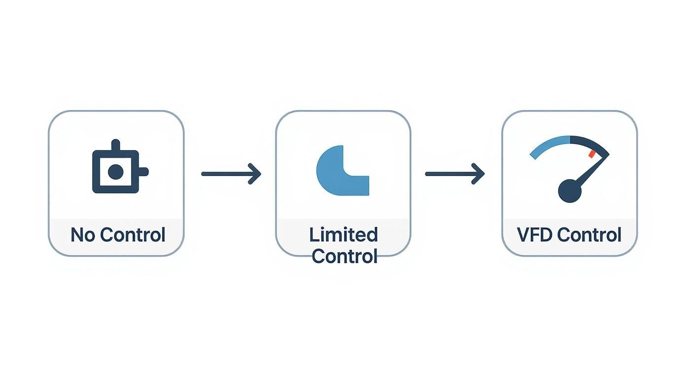
You can see it right there. A VFD opens up a full spectrum of speed regulation, blowing past the all-or-nothing limitations of a direct-on-line starter.
Stage 1: The Rectifier
The journey starts at the rectifier. This is the VFD's front door, where the standard AC power from the grid—the stuff coming out of the wall—first enters the drive.
A rectifier is basically a one-way electrical gate. It’s made up of diodes that take the incoming AC power, which is constantly flipping its direction, and converts it into direct current (DC) power, which flows in one steady direction.
This is the essential first step. You can't just grab AC power and change its frequency on the fly. You have to break it down into a more basic form of energy—DC—before you can build it back up the way you want it.
Stage 2: The DC Bus
After conversion, that raw DC power flows into the DC bus (sometimes called the DC link). Think of this section as a power reservoir and a smoothing station.
The DC coming from the rectifier isn't perfectly clean; it has ripples and little fluctuations. So, the DC bus uses a bank of large capacitors to filter out these bumps, creating a clean, stable pool of DC voltage.
The capacitors act like a small water tank in a plumbing system. They absorb any surges and fill in any dips, ensuring the next stage has a perfectly consistent source of energy to draw from. This clean DC voltage is the raw material needed to create the new, adjustable AC output.
The rectifier and DC bus work as a team to create a clean slate. They take messy grid power, convert it to a stable DC voltage, and set the stage for the inverter to do its real magic.
This intermediate step is a non-negotiable part of how a VFD works, and it's what ensures a high-quality, reliable output for the motor.
Stage 3: The Inverter
This is where the magic really happens. The inverter is the final stage, and it’s responsible for creating a brand-new AC waveform with a completely controllable frequency and voltage.
The inverter is built from a set of incredibly fast electronic switches, usually Insulated Gate Bipolar Transistors (IGBTs). These switches are the workhorses of the drive, turning on and off thousands of times per second to chop the smooth DC voltage from the bus into a series of precisely timed pulses. This technique has a name: Pulse Width Modulation (PWM).
By controlling the exact timing and width of these pulses, the inverter can stitch them together to create a simulated AC sine wave. And here’s the brilliant part: it can build this wave at any frequency it’s told to.
- To make the motor run slower, it creates a lower-frequency wave.
- To make it run faster, it builds a higher-frequency wave.
At the same time, the inverter adjusts the voltage up or down in sync with the frequency, which is crucial for maintaining the motor's torque. This is what gives a VFD such precise and stable control over a motor's speed without making it weak or unstable. From raw grid power to a finely tuned output, that three-stage process is how a VFD puts you in complete command of your motor.
Picking the Right VFD Control Method
A VFD isn't just a simple box that throttles power up and down. It has a 'brain' inside—its control method—that dictates exactly how it bosses the motor around. Getting this choice right is crucial. You have to match the drive's smarts to what your application actually needs.
Think of it like this: are you driving a family sedan on the highway or a race car on a track? The sedan’s simple cruise control is perfect for its job, but the race car needs a sophisticated traction control system that can react in milliseconds. Both manage speed, but with totally different levels of precision and feedback. Picking the right VFD control method ensures you get the performance you need without overpaying for complexity you'll never use.
The Workhorse: Volts per Hertz Control
The most common and straightforward method is Volts per Hertz (V/Hz), often called scalar control. The logic behind it is beautifully simple: to keep the motor's torque output steady, the VFD maintains a constant ratio between the voltage and the frequency it sends out. As it ramps up the frequency to make the motor spin faster, it proportionally boosts the voltage.
This reliable, no-fuss approach is the go-to for a huge range of applications where pinpoint precision isn't the main goal. It’s a perfect fit for variable torque loads, where the torque needed naturally increases with speed.
Common places you'll see V/Hz in action:
- Centrifugal Pumps and Fans: This is the classic example. A fan spinning faster needs more torque to move more air, and the V/Hz curve matches this relationship perfectly.
- Simple Conveyors: For basic systems moving consistent loads at different speeds, V/Hz gives you all the control you need.
- Blowers and Agitators: Most mixing and air-moving jobs benefit from the sheer simplicity and cost-effectiveness of this mode.
The real beauty of V/Hz is its simplicity and toughness. It doesn't need any complex feedback from the motor, which makes it robust, a breeze to set up, and the most economical choice for about 80% of all standard VFD applications.
The Precision Athlete: Vector Control
When your application demands tight, responsive control over torque, especially at very low speeds, you need to step up to Vector Control. Forget the simple ratio of V/Hz. Vector control builds a sophisticated mathematical model of the motor right inside the VFD's processor. This allows it to independently control the two key parts of the motor's current: the current that creates the magnetic field (flux) and the current that actually produces the torque.
That separation is the game-changer. It gives the VFD the power to control the motor's torque with the kind of precision you'd normally only expect from a DC drive, even when the motor is barely turning or holding a load at zero speed. Vector control comes in two main flavors.
Sensorless Vector Control
Sensorless Vector Control (SVC) pulls off this high-performance trick without needing any physical sensor on the motor itself. The drive uses its internal motor model and constantly analyzes tiny electrical changes to accurately estimate the motor's speed and position.
SVC delivers fantastic performance for most demanding constant torque applications, like:
- Extruders and industrial mixers
- Positive displacement pumps
- Machine tools like lathes and milling machines
Closed-Loop Vector Control
For the absolute highest level of precision, you have Closed-Loop Vector Control, sometimes called Field Oriented Control (FOC). This method adds a physical speed sensor—usually an encoder—right onto the motor shaft. That encoder feeds real-time, high-resolution speed and position data directly back to the VFD.
With that direct feedback loop, the drive knows exactly what the motor shaft is doing at every single moment. This enables almost perfect torque and speed regulation. It's the top-tier choice for applications like web handling, cranes, and high-speed spindles where even the slightest error can ruin a product or cause a safety issue.
As you start designing more sophisticated systems like these, looking into options for custom controls and system integration becomes critical to really harness this level of precision.
To help you decide, here’s a quick breakdown of how these methods stack up against each other.
Comparison of VFD Control Methods
This table compares the key characteristics, typical applications, and performance trade-offs of the most common VFD control methods.
| Control Method | Key Principle | Typical Applications | Performance Level | Relative Cost |
|---|---|---|---|---|
| V/Hz (Scalar) | Maintains a constant voltage-to-frequency ratio. | Fans, centrifugal pumps, simple conveyors. | Basic speed control, poor low-speed torque. | Low |
| Sensorless Vector | Uses a motor model to control torque and flux independently. | Extruders, mixers, machine tools, general machinery. | Good speed/torque control across a wide range. | Medium |
| Closed-Loop Vector | Uses an encoder for precise feedback on motor shaft position. | Cranes, hoists, web lines, high-precision spindles. | Excellent, precise control even at zero speed. | High |
Ultimately, the goal is to match the control method's capabilities—and cost—to the real-world demands of your machine. There's no sense in using a high-performance vector drive on a simple ventilation fan, just as you wouldn't get away with a basic V/Hz drive on a precision winding machine.
How to Select and Size Your VFD Correctly
Choosing the right Variable Frequency Drive is about more than just matching up horsepower ratings. When you get down to it, a solid VFD selection hinges on a careful look at the motor, the real-world demands of the application, and the environment it has to live in.
Nailing this from the get-go saves you from a world of hurt later on—from frustrating nuisance trips to catastrophic equipment failure.
The whole process starts with the motor. The nameplate isn't just a sticker; it's the source of truth, packed with the non-negotiable data you need to size the drive properly. Skipping this step is a classic, and often costly, mistake.

Start with the Motor Nameplate
First things first, you need to grab the critical stats directly from the motor you plan on controlling. This information is your baseline.
- Full-Load Amps (FLA): This is the big one. Always size the VFD based on the motor's FLA, not its horsepower. A VFD’s main job is managing current, so its continuous and peak current ratings have to meet or, even better, exceed what the motor demands.
- Voltage: The VFD's input voltage must match your available supply (e.g., 480V 3-phase), and its output needs to be configured for the motor’s rated voltage. Simple, but crucial.
- Service Factor (SF): See a service factor above 1.0, like 1.15? That means the motor can handle a bit of an overload for short bursts. If you plan to actually use that extra muscle, you better pick a VFD that can dish out the extra current without tripping on fault.
Analyze the Application Load Profile
Next, you have to get a feel for the kind of work the motor is actually doing. Loads generally fall into two buckets, and each one puts a very different kind of strain on a drive.
Variable Torque Loads
Think centrifugal pumps and fans. These are applications where the torque needed ramps up with speed. We often call these the "easy" loads because they demand very little torque to get going at low speeds. A standard-duty VFD is usually the perfect, and most cost-effective, choice here.
Constant Torque Loads
These are the heavy lifters. We're talking about conveyors, mixers, extruders, and positive displacement pumps that need nearly full torque right from a dead stop. For these tough jobs, you absolutely need a heavy-duty or constant torque-rated VFD. These drives are built with beefier components specifically to handle massive starting currents without breaking a sweat.
A classic sizing error is throwing a standard-duty drive at a constant torque application. It’s a recipe for overcurrent faults and, eventually, a dead drive, because it simply wasn't designed to deliver that kind of starting punch.
Consider Environmental and System Factors
The physical world and the rest of your control system have a huge say in a VFD's survival. A drive that looks perfect on paper can fail in a hurry if you ignore its surroundings.
It also helps to know the lay of the land. For instance, low voltage VFDs commanded a 60.8% market share recently, and AC drives make up about 70% of total sales. With the low-power segment holding a massive 41% revenue share, it’s a good sign that many jobs fall into standard categories, which can make selection easier. You can dig into the numbers in this variable frequency drive market analysis.
Here’s a final checklist of things you can't afford to overlook:
- Ambient Temperature: VFDs make heat. You have to make sure the spot you're installing it won't get hotter than the drive's rating (usually 40°C or 104°F). If it’s going in a hotbox, you’ll need to oversize the drive or engineer some extra cooling.
- Enclosure Type: Is the drive going in a pristine control room or out on a dusty, grimy factory floor? You have to pick the right enclosure—like a NEMA 1, NEMA 12, or a washdown-ready NEMA 4X—to shield it from dust and moisture.
- I/O and Communications: Make a list of every input and output you need. Analog signal for a pressure sensor? Digital inputs for start/stop buttons? Does it need to talk to a PLC over a network like EtherNet/IP or Modbus? Make sure the drive has the ports you need or can be expanded to get the job done.
By methodically working through the motor data, load profile, and environmental factors, you can confidently pick a VFD that’s not just the right size, but is perfectly suited for years of reliable performance.
VFD Installation and Wiring Best Practices
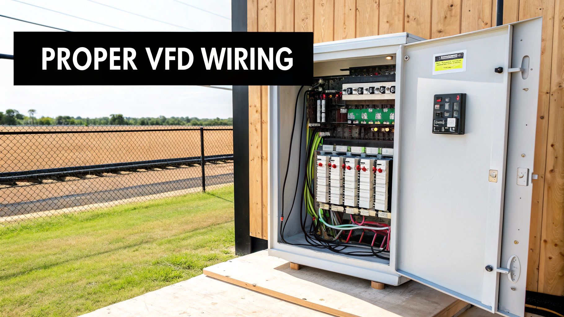
You can pick the perfect drive for the job, but if the installation is sloppy, it can still fail spectacularly. The road from the box to a smoothly running system is paved with small details that make a huge difference in performance, safety, and long-term reliability.
Following best practices isn't just about ticking a box for the electrical inspector; it's about protecting your investment. A properly installed drive runs quieter, is much safer, and is far less likely to cause electrical chaos for other equipment on the line.
Managing Heat with Proper Ventilation
VFDs are power conversion machines, and that process of converting AC to DC and back to AC again creates a lot of heat. Getting that heat away from the drive is arguably the most critical factor for its survival. Overheating is the number one killer of power electronics.
To keep things cool, you have to give the drive room to breathe. That means paying close attention to the manufacturer's specified clearances on the top, bottom, and sides. Boxing a drive in without proper airflow is a surefire way to cook its internal components and send it to an early grave.
- Mind the Airflow: Never block the vents. In an enclosed panel, this almost always means installing fans and filters to pull cool air in from the bottom and push hot air out the top.
- Check the Room Temp: The ambient temperature of the room matters. Most VFDs are happy up to 40°C (104°F). If your environment is hotter than that, you'll need to either oversize the drive or look into more serious cooling solutions.
Establishing a Rock-Solid Grounding System
Good grounding is completely non-negotiable. It's about safety, first and foremost, but it’s also essential for reliable performance. A solid, low-impedance ground connection is your best defense against electrical shock and your primary tool for taming electrical noise.
The high-speed switching inside a VFD creates a ton of electrical noise, known as electromagnetic interference (EMI). A proper ground gives that noise a safe and easy path to dissipate, keeping it from messing with sensitive electronics like PLCs and sensors.
Think of a proper ground as the foundation of your entire VFD installation. It ensures personnel safety, protects the drive from electrical faults, and helps contain the high-frequency noise that is a natural byproduct of the VFD's operation.
Using Shielded Cable and Separating Wires
Fighting EMI is a huge part of a quality VFD installation. The best way to win that fight is by using the right kind of wire and being smart about where you run it.
For the cable running from the VFD to the motor, always use shielded motor cable. The shield acts like a cage, capturing the electrical noise coming off the drive's output and funneling it safely to ground. Without it, your motor cable becomes a giant antenna, broadcasting interference all over your facility.
It’s also crucial to keep your power and control wires physically separated. A good rule of thumb is to maintain at least 8-12 inches of space between high-voltage power wiring (like the motor leads) and low-voltage control wiring (like your start/stop signals or speed reference). The gold standard is to run them in separate conduits altogether.
This separation prevents the powerful magnetic fields around the power cables from inducing "crosstalk" into your control signals, which can cause all sorts of unpredictable behavior. For complex systems, getting expert advice on system integration can save you from a world of noise-related headaches. By focusing on these core principles—cooling, grounding, and shielding—you lay the groundwork for a VFD installation that is robust, safe, and reliable.
Troubleshooting Common VFD Faults
When your VFD grinds to a halt and flashes a fault code, it’s not being cryptic—it's trying to tell you exactly what’s wrong. Learning to speak its language is the first step to slashing downtime. This is your first-response guide for the most common issues you'll run into out in the field.
Think of a fault code as a specific symptom. Instead of a vague "the system is sick" message, the drive points directly to where it hurts. Once you understand what these codes mean, you can jump from diagnosis to solution in minutes, often without having to call for backup.
Decoding Overcurrent Faults
An Overcurrent (OC) fault is probably the one you'll see most often. It simply means the drive saw a current spike that shot past its safety limits, so it shut down to protect itself and the motor. This isn't just a random glitch; it's a clear sign of a mechanical or electrical problem that needs attention.
You’re usually looking at one of three things:
- Something is jammed. A conveyor belt gets stuck, a pump is clogged with debris, or a machine tool binds up. Any sudden physical resistance will force the motor to pull way too much current.
- The ramps are too aggressive. You've set the acceleration or deceleration time too short. Trying to get a heavy load moving or stopped in a fraction of a second demands a massive, often unsustainable, surge of current.
- A dead short. A short circuit in the motor windings or in the cable running between the drive and the motor will trigger a huge, instantaneous current spike.
First Response Checklist: Before you even think about hitting the reset button, go put your eyes on the machine. Is anything physically jammed or blocked? If the load seems to move freely, pop into the VFD's parameters and check the acceleration time. Try adding a few seconds to the ramp.
Managing Overvoltage Faults
An Overvoltage (OV) fault trips when the voltage on the drive's DC bus climbs too high. Interestingly, this usually doesn't happen when the motor is speeding up, but when it's slowing down. A motor that's being forced to decelerate effectively turns into a generator, pumping power back into the drive.
All that regenerative energy has to go somewhere. If it has nowhere to escape, it inflates the DC bus voltage until it hits a dangerous level, and the drive faults out to protect itself.
The main culprits here are:
- Too much regeneration. This is classic in applications with a lot of inertia, like big industrial fans, flywheels, or centrifuges. It also happens when a hoist is lowering a heavy load and the motor is being "overhauled" or pushed by gravity.
- Deceleration is too fast. Just like with overcurrent, setting the deceleration ramp too short forces the drive to absorb a massive amount of energy in a very short time.
- High line voltage. Sometimes the problem isn't the load at all. A sudden spike from the utility or consistently high incoming AC voltage can be enough to push the DC bus over its limit.
The first fix to try is easy: increase the deceleration time. Give the drive more time to bleed off that energy. If that doesn't cut it, your application probably needs a dynamic braking resistor. Think of it as a safety valve. This resistor gives all that excess regenerative energy a path to be safely burned off as heat, keeping the DC bus stable and the drive online. Understanding the fundamentals of how a variable frequency drive manages energy flow is key here.
VFD Questions from the Field
Even after you get the hang of VFDs, a few practical questions always seem to pop up on the job site. Here are the answers to the ones we hear most often from technicians and engineers trying to get things running smoothly.
Can I Just Slap a VFD on Any Old Motor?
Not really, and you probably shouldn't. While a VFD can technically make most three-phase AC induction motors spin, it's a risky move for the motor's health. The smart play is to pair your drive with a proper inverter-duty motor.
Why? Inverter-duty motors are built tougher. They have beefed-up insulation designed specifically to handle the sharp, high-voltage pulses a VFD puts out. Throwing a standard motor on a drive, especially if you plan to run it slow for long periods, is asking for it to overheat and burn out its windings. Always check the motor's nameplate or spec sheet to make sure it's rated for VFD use.
Do I Really Need to Use Shielded VFD Cable?
Yes. Absolutely. Think of it this way: a VFD doesn't create a nice, clean sine wave. It chops up DC voltage into a high-frequency pulsed waveform to simulate one. That process generates a massive amount of electrical noise, or electromagnetic interference (EMI).
If you use regular unshielded wire, you've just turned that cable into a giant radio antenna, broadcasting that noise all over your plant. That EMI can wreak havoc on your other systems—messing with PLCs, scrambling sensor readings, and disrupting network communications. Shielded VFD cable traps that noise and gives it a clean path to ground, keeping the rest of your facility electrically quiet.
Don't treat shielded motor cable as an optional extra. It's non-negotiable for a stable, reliable installation. It protects the drive, the motor, and every other piece of sensitive electronics you've got from crippling electrical interference.
What's the Deal with Dynamic Braking?
Dynamic braking is all about stopping a heavy, spinning load without tripping the drive. When you command a VFD to slow down a motor with a lot of inertia—like a big fan or a heavy conveyor—that motor temporarily turns into a generator. It starts feeding power back into the VFD.
If that extra energy has nowhere to go, the drive’s DC bus voltage spikes, and it shuts down on an overvoltage fault. A dynamic braking resistor is the solution. It’s basically a big heater connected to the drive that acts as a pressure relief valve, safely burning off that excess electrical energy as heat. This lets you slam on the brakes and bring heavy loads to a fast, controlled stop.
At E & I Sales, we don't just ship boxes. We're the engineering partner you call to figure out the right motor control solution for your most demanding jobs. Let's build your next project together.