
Getting the pairing between a circuit breaker and its corresponding wire size right is the absolute foundation of a safe electrical system. It's what prevents wires from overheating and creating a serious fire risk. At a glance, the most common pairings are a 15-amp breaker with 14 AWG copper wire, a 20-amp breaker with 12 AWG copper wire, and a 30-amp breaker with 10 AWG copper wire. This core relationship ensures the breaker will always trip before the wire's insulation is ever compromised by heat.
Standard Breaker and Wire Size Pairings (NEC Compliant)
This table offers a quick reference for standard THHN/THWN-2 conductors where terminations are rated for 75°C and conditions are normal. Remember, this is a starting point—always apply the necessary derating factors for your specific industrial application.
| Circuit Breaker Rating (Amps) | Minimum Copper Wire Size (AWG) | Minimum Aluminum Wire Size (AWG) |
|---|---|---|
| 15A | 14 | 12 |
| 20A | 12 | 10 |
| 25A | 10 | 8 |
| 30A | 10 | 8 |
| 40A | 8 | 6 |
| 50A | 8 | 6 |
| 60A | 6 | 4 |
| 70A | 4 | 3 |
| 80A | 4 | 2 |
| 90A | 3 | 1 |
| 100A | 3 | 1/0 |
| 125A | 1 | 3/0 |
| 150A | 1/0 | 4/0 |
| 175A | 2/0 | 250 kcmil |
| 200A | 3/0 | 350 kcmil |
Think of these pairings as the baseline. Real-world conditions often require adjustments, which we'll get into later.
Why Is a Breaker and Wire Size Chart So Important?
For any engineer, technician, or electrician in the field, a reliable circuit breaker to wire size chart is an indispensable tool. It serves as a quick, NEC-aligned reference to confirm that the conductor you’ve chosen can safely carry the maximum current its breaker will allow.
If you get this pairing wrong, you create an incredibly dangerous scenario where a wire can overheat long before its breaker even thinks about tripping. That’s a massive fire hazard. This guide is built to give you both the chart and the detailed know-how to design safe, compliant industrial systems.
Understanding this relationship is non-negotiable for any electrical work. It's the basis for more advanced calculations that factor in conductor material, ambient temperature, and specific load types. For instance, knowing the safe current for different outlets is critical when considering specialized applications, like charging an electric car from a standard 13-amp socket.
The Principles Behind the Chart
To really use a reference chart like this effectively, you have to understand the core principles driving the numbers. This ensures you're making safe decisions that go beyond just matching a number to a wire gauge.
- Overcurrent Prevention: The entire point is to protect the wire. The breaker is designed to be the "weak link" in the circuit, shutting things down before the conductor's insulation can be damaged by heat from excessive current.
- Ampacity Is Key: Every wire has a maximum current it can safely handle, a rating we call ampacity. This is determined by its size (gauge), what it's made of (copper vs. aluminum), and its insulation's temperature rating.
- NEC Compliance: In the United States, all of these pairings must meet the minimum safety standards laid out in the National Electrical Code (NEC). No exceptions.
This chart gives you a quick visual of the standard pairings you'll encounter in most applications.
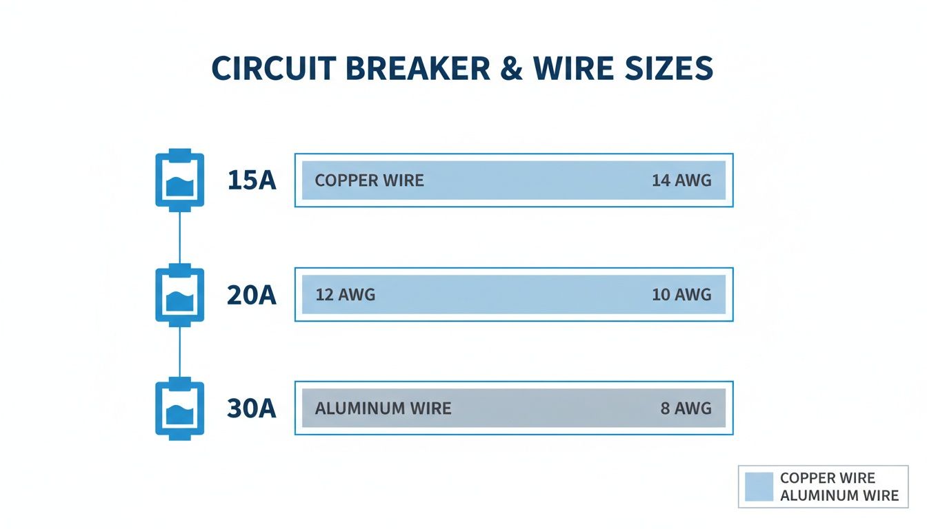
It’s a simple concept: as the amperage goes up, the wire has to get bigger to handle the load safely. For a deeper dive into selecting the right overcurrent protection for your project, our guide on circuit breaker sizing provides even more context.
Decoding Wire Gauge and Conductor Fundamentals
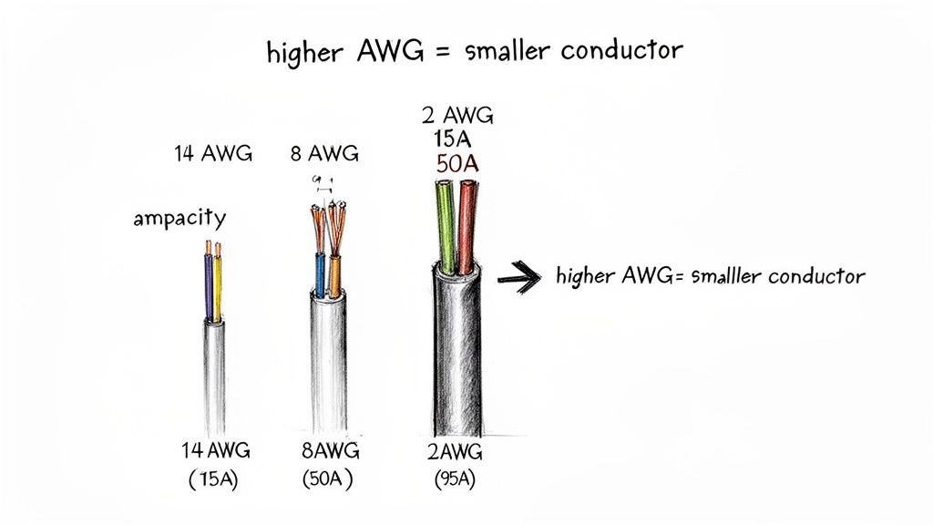
Before you can really put a circuit breaker to wire size chart to work, you have to speak the language of conductors. The bedrock of North American electrical standards is the American Wire Gauge (AWG) system. It's a simple numbering scale, but it trips people up all the time.
Why? Because it's inverse. A smaller AWG number means a bigger, beefier wire with a larger diameter. So, a 10 AWG wire is physically larger and can safely handle more current than a 14 AWG wire. Getting this one concept right is the first step in designing a safe, reliable circuit.
This system wasn't just pulled out of thin air. It goes all the way back to the mechanical wire-drawing processes of the 1850s. The AWG system is logarithmic, which means each step up or down in gauge represents a consistent, proportional change in size. While the history is fascinating, what matters for us is its mathematical precision.
The Role of Cross-Sectional Area and Ampacity
A wire’s gauge is all about its cross-sectional area. This single factor is what determines its current-carrying capacity, or ampacity. Think of it like a hose—a wider hose can move more water with less friction. In the same way, a wire with a bigger cross-section has less resistance to electron flow.
Less resistance means less heat builds up as current runs through it. If you push too much current through a wire (exceeding its ampacity), it will overheat. That’s when insulation melts and you get a serious fire hazard.
A conductor's ampacity isn't just a number on a chart; it's a thermal limit. The entire point of proper wire sizing is to make sure the conductor never gets hotter than what its insulation can handle, even under a full load.
Solid vs. Stranded Conductors
You'll also run into two main types of conductors: solid and stranded. Each has its place in industrial settings, and choosing the right one matters.
- Solid Conductors: These are made from a single, solid piece of metal. They're rigid, more affordable, and resist corrosion well. This makes them a great choice for permanent, stationary installations inside conduits where they won't be bent or vibrated.
- Stranded Conductors: These are built from many smaller wires twisted together into a bundle. This construction makes them far more flexible. You'll want to use stranded wire anywhere you expect vibration, frequent movement (like on a machine or in a control panel door), or have to pull it through tight, complex conduit runs.
Even though a solid and a stranded wire of the same AWG have the same total cross-sectional area and a nearly identical ampacity, how you can use them is completely different. Nailing down these fundamentals gives you the foundation you need to correctly read and apply any circuit breaker to wire size chart, ensuring your work is both efficient and—most importantly—safe.
Choosing the Right Conductor Material and Insulation
Picking the right wire gauge from a circuit breaker to wire size chart is just the start. The materials you’re working with—the conductor itself and the insulation wrapped around it—are just as critical for a safe, code-compliant job that will last. You'll mainly run into two types of conductors: copper and aluminum. Each has its place.
Copper is the gold standard for a reason. It’s got fantastic conductivity, it's strong, and it resists corrosion like a champ. All that means it can carry more current than an aluminum wire of the same physical size.
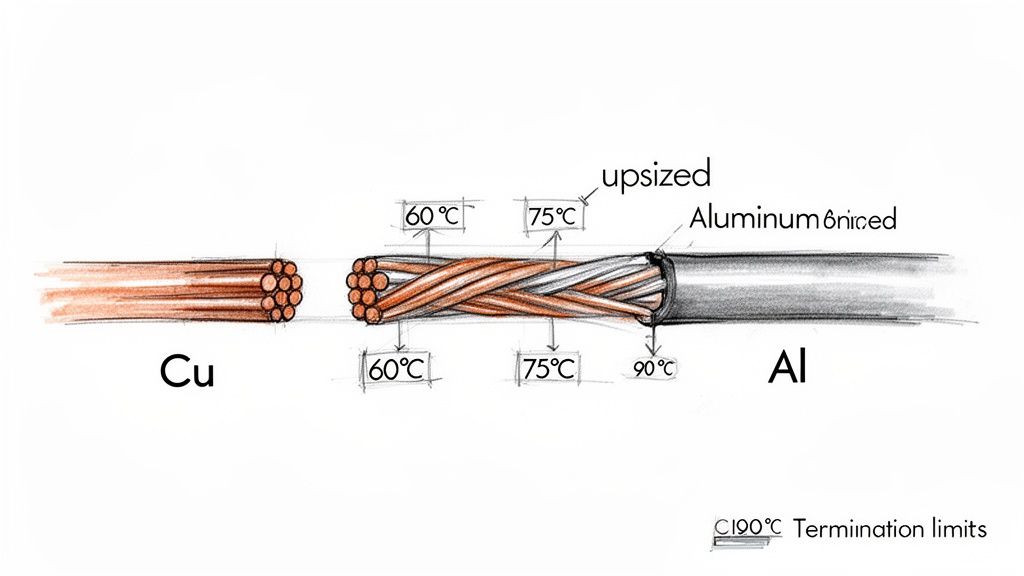
Aluminum is lighter and often cheaper, but it doesn't conduct electricity as well. Because of that lower conductivity, you always have to upsize the wire gauge to match the ampacity of a copper equivalent. For instance, a 50A circuit that calls for 8 AWG copper would need a bigger 6 AWG aluminum wire. You also have to be meticulous with terminations, using an anti-oxidant compound to stop corrosion and prevent dangerous connection failures down the road.
Understanding Insulation Temperature Ratings
The insulation is the wire's primary defense against heat buildup. Different insulation compounds have different temperature limits, and that rating directly affects how much current the wire can safely handle (its ampacity).
In the NEC ampacity tables, you'll see three main temperature columns:
- 60°C (140°F): This is the lowest rating, mostly seen on older NM (non-metallic) cables. It gives you the lowest ampacity for any given wire size.
- 75°C (167°F): Think of this as the modern standard. Most circuit breakers and equipment terminals are rated for this temperature, making it the go-to column for most final ampacity calculations.
- 90°C (194°F): This higher rating is for high-performance insulation like THHN (Thermoplastic High Heat-resistant Nylon-coated) and XHHW (Cross-linked High Heat-resistant Water-resistant).
Now, you might see a wire is rated for 90°C and think you can use its higher ampacity value. Not so fast. The NEC has a critical rule that changes the entire calculation.
The Weakest Link Rule in Ampacity
According to NEC 110.14(C), the ampacity of any circuit is strictly limited by the lowest temperature rating of any single component in the entire chain. That includes the wire, the breaker terminals, and the lugs on the equipment at the other end.
Since most circuit breakers and termination lugs are only rated for 75°C, you are required to use the wire’s ampacity from the 75°C column for your final calculation, even if the wire itself is a 90°C THHN. It’s a common mix-up, but it's a safety rule you can't ignore.
So, what's the point of the 90°C rating? It's your starting line for derating. When you have to account for high ambient heat or you're bundling a bunch of conductors in a conduit, you begin with the wire's higher 90°C ampacity. This gives you more room to apply correction factors, but the final, derated ampacity still can't be higher than what's allowed for that wire in the 75°C column.
How to Apply Derating Factors for Real-World Conditions
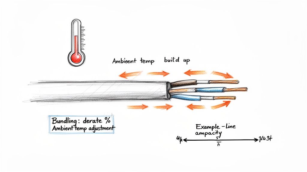
Standard ampacity charts are a fantastic starting point, but they’re based on ideal lab conditions. Out in the field, things are rarely perfect. Wires snake through hot boiler rooms, get baked in sun-drenched attics, or are packed tightly into conduits with a dozen other circuits. These real-world scenarios create heat, and that’s where derating becomes one of the most critical safety calculations you can make.
Derating is simply the process of reducing a wire's allowable ampacity to account for conditions that prevent it from cooling effectively. Skipping this step isn't just bad practice; it's a direct violation of the National Electrical Code (NEC) and a serious fire hazard. It's how we guarantee a wire’s insulation never cooks, even when the environment is working against it. The two biggest culprits we have to account for are ambient temperature and conductor bundling.
Adjusting for Ambient Temperature
NEC ampacity tables use a standard baseline temperature of 86°F (30°C). Anytime your conductors run through a space that’s hotter than that, their ability to shed heat is compromised. To compensate, we have to lower their safe current-carrying capacity. The NEC gives us the exact correction factors for this in Table 310.15(B)(1).
Key Takeaway: Here’s a pro tip that’s crucial for getting this right. You must start your calculation using the conductor’s highest insulation rating—typically 90°C for THHN wire. You still have to obey the lower 75°C limit for the final ampacity at the terminals, but starting with the higher 90°C value gives you more headroom for the reduction. This often prevents you from having to upsize the wire unnecessarily.
Let's say you're running 3 AWG THHN copper wire through a space with an ambient temperature of 110°F (43°C). The base ampacity of that wire at 90°C is 115A. Looking at the table, the correction factor for that temperature is 0.87.
- The math is straightforward: 115A (90°C ampacity) × 0.87 (correction factor) = 100.05A
Just like that, the new, safely derated ampacity is 100.05 amps.
Accounting for Conductor Bundling
The other big factor is how many wires are stuffed into one pipe. When you group multiple current-carrying conductors in a single raceway for more than 24 inches, their heat gets trapped. They can't cool off. The NEC addresses this with adjustment factors in Table 310.15(C)(1).
- 1-3 conductors: No adjustment needed. You're at 100% of the value.
- 4-6 conductors: You must reduce the ampacity to 80%.
- 7-9 conductors: The value drops to 70%.
- 10-20 conductors: You're down to just 50% of the original ampacity.
Putting It All Together: A Practical Example
Now, let’s combine both derating factors to see how dramatic the effect can be. Imagine you have nine current-carrying 3 AWG THHN copper conductors packed into a single conduit, and that conduit runs through that same 110°F room.
- Start with the 90°C Ampacity: The book value for 3 AWG THHN is 115A.
- Apply Temperature Correction: 115A × 0.87 (for 110°F) = 100.05A.
- Apply Bundling Adjustment: Now, take that new value and multiply it by the bundling factor. 100.05A × 0.70 (for 7-9 conductors) = 70.04A.
After both adjustments, the true, safe ampacity of each of those wires is only 70.04A. You'd have to protect this circuit with a 70A breaker. That's a huge drop from the 115A we started with, and it perfectly illustrates why you can never skip these real-world calculations. If you run into more complex installations, you can find extra guidance in our article covering the NEC tap rule.
Sizing Conductors for Motors and Continuous Loads
While standard circuits follow predictable rules, the real world of industrial electricity is full of exceptions. Motors and continuous loads, in particular, generate unique thermal stresses on a circuit, and you can't rely on a basic circuit breaker to wire size chart for them. These applications are where a deep-seated understanding of the National Electrical Code (NEC) becomes absolutely critical for both safety and reliability.
A continuous load is defined by the NEC as any load that pulls its maximum current for three hours or more. Think about the big power consumers in an industrial plant: massive HVAC systems, huge lighting arrays, and process heaters. That prolonged current flow generates a ton of sustained heat in the conductors—heat that standard sizing practices just don't account for.
To deal with this, NEC 210.19(A)(1) lays out a crucial rule: conductors feeding continuous loads have to be sized to handle 125% of the load's maximum current. The breaker gets the same treatment. Per NEC 210.20(A), it also has to be sized to 125% of the load. This buffer is a non-negotiable safety margin that ensures the wiring and breaker can handle the long-term thermal punishment without failing.
The 125 Percent Rule in Action
Let’s walk through how this works on the job. Imagine you're wiring a bank of industrial heaters that draw a combined 24 amps and will run for an entire 8-hour shift.
- Calculate the Required Ampacity: Since this is clearly a continuous load, you apply the 125% rule.
- 24A × 1.25 = 30A
- Size the Conductor: Now you need a wire with an ampacity of at least 30A. Looking at the 75°C column of the NEC ampacity table, that points directly to a 10 AWG copper conductor.
- Select the Breaker: The breaker must also be rated for the calculated load, so you'll install a 30A breaker to protect the circuit.
Special Sizing Rules for Motor Circuits
Motors are a whole different beast and are probably the most complex loads to size correctly. The problem is the massive, momentary inrush current they draw during startup, which can be six to eight times their normal running current. A standard breaker sized for the running load would trip every single time. Because of this, motor circuits get their own dedicated rules under NEC Article 430.
The invention of the miniature circuit breaker (MCB) back in 1924 was a major leap forward that made modern motor protection possible. Before that, everyone relied on simple fuses. The first practical MCB had a dual-mechanism design—a thermal element for slow-burn overloads and a magnetic coil for instant short-circuit trips—a principle that still helps us manage motor startups today. You can get the full story on the evolution of these critical safety systems and how they began.
The NEC handles motor protection in two distinct parts: short-circuit and ground-fault protection (your breaker or fuse) and overload protection (a separate device, often in the motor starter). The wire size is actually based on the motor's full-load current (FLC), while the breaker is intentionally oversized to let that startup inrush happen without tripping.
This is a critical distinction. It means the breaker's rating in a motor circuit is often significantly higher than what the wire's ampacity would normally permit. For instance, a motor might need 10 AWG wire (rated for 30A) but be protected by a 60A breaker just to handle the startup surge. This is a specific, well-defined exception in the NEC, and it's the perfect example of why you can't use a standard chart for motor applications.
How to Calculate and Manage Voltage Drop
Ampacity and derating are crucial, but on long wire runs, another factor enters the game: voltage drop. As electricity makes its way down a conductor, the wire’s own resistance causes a small but steady loss in voltage. This is nothing to worry about over short distances, but it can become a serious issue in large industrial facilities where equipment might sit hundreds of feet from its power source.
When voltage drop gets excessive, it essentially starves equipment of the power it needs. This can lead to all sorts of problems, like poor performance, motors overheating, and even premature failure. To head this off, the NEC recommends keeping voltage drop to 3% for branch circuits and no more than a total of 5% for the entire system, from the service entrance right down to the final piece of equipment.
The Voltage Drop Calculation
So, how do you know if you need to upsize your conductor? You have to calculate the expected voltage drop. For a single-phase circuit, the formula is straightforward:
VD = (2 x K x I x D) / CM
For three-phase circuits, which are common in industrial settings, it's a bit different:
VD = (1.732 x K x I x D) / CM
Here's a breakdown of those variables:
- VD: Voltage Drop
- K: This is the electrical resistivity for the conductor material. It’s a constant, roughly 12.9 for copper and 21.2 for aluminum.
- I: The load current, measured in amperes.
- D: The one-way distance of the circuit in feet.
- CM: The circular mils of the conductor. You can look this value up in NEC Chapter 9, Table 8.
Practical Example for an Industrial Motor
Let's put this into a real-world context. Picture a 480V, three-phase motor that's a good 250 feet away from its control panel. The motor's full-load current (FLA) is 24 amps. Based on ampacity alone, we initially decided to use 10 AWG copper wire, which has a circular mil value (CM) of 10,380.
First, we need to figure out our maximum acceptable voltage drop:
- 480V x 3% = 14.4V
Now, let's calculate the actual voltage drop we’d get with that 10 AWG wire:
- VD = (1.732 x 12.9 x 24A x 250 ft) / 10,380 CM
- VD = 133,934.4 / 10,380
- VD = 12.9V
In this situation, our calculated drop of 12.9V is safely under the 14.4V limit, so the 10 AWG wire is good to go. If that number had come out higher than 14.4V, we would have to move up to the next wire size (8 AWG) and run the calculation again until the result fell within that 3% window.
Getting this right is a critical step for ensuring equipment longevity and overall system efficiency. For a deeper dive into these calculations, check out our guide on voltage drop calculation formulas.
Working With International and Metric Wire Sizes
If you're dealing with equipment on a global scale, you'll quickly run into a different set of rules for wire sizing. While we're used to the American Wire Gauge (AWG) system here in North America, most of the world operates on the IEC 60228 standard. This system is much more direct—it sizes conductors by their actual cross-sectional area in square millimeters (mm²).
It's not just a simple matter of converting units. These two systems grew up on entirely different tracks. AWG is rooted in the manufacturing process, a logarithmic scale that made sense for how wire was drawn. The IEC standard, on the other hand, follows a more straightforward mathematical progression. This split created two parallel universes for electrical design, and anyone specifying parts for imported machinery or designing systems for export has to be fluent in both. You can actually dive deeper into the history of these sizing standards to see how they evolved.
Knowing how to bridge this gap is critical for any international project.
The Essentials of AWG to Metric Conversion
Here’s the catch: you won't always find a perfect, direct match between an AWG size and a metric mm² size. It’s more about finding the closest equivalent that can safely handle the required amperage. Trying to guess or eyeball it is a recipe for expensive mistakes, so a reliable conversion chart is your best friend.
This is where a good circuit breaker to wire size chart that includes metric equivalents becomes an indispensable tool. Below is a common reference table that helps bridge the gap between North American and international wiring practices.
| AWG Size | Metric Size (mm²) |
|---|---|
| 14 AWG | 2.5 mm² |
| 12 AWG | 4 mm² |
| 10 AWG | 6 mm² |
| 8 AWG | 10 mm² |
| 6 AWG | 16 mm² |
| 4 AWG | 25 mm² |
| 2 AWG | 35 mm² |
| 1/0 AWG | 50 mm² |
| 2/0 AWG | 70 mm² |
| 4/0 AWG | 95 mm² |
| 250 kcmil | 120 mm² |
A Critical Point: Don't just match up the physical dimensions and call it a day. You must verify the ampacity ratings under both the NEC and any relevant IEC standards. The conductor has to handle the circuit's load safely according to local codes. If you're stuck between sizes, the golden rule is to always round up to the next largest metric wire to give yourself a solid safety margin.
Common Questions on Wire Sizing
When you're staring at a circuit breaker to wire size chart, a few common questions always seem to pop up. Getting these right is non-negotiable for a safe, NEC-compliant installation. Let's clear up some of the most frequent points of confusion.
Can I Use the 90°C Ampacity for a THHN Wire?
This is a big one, and the answer is almost always no, you can't use the 90°C rating for your final circuit protection.
Even though a wire like THHN is rated for 90°C, NEC 110.14(C) throws a wrench in the works. It states that a circuit's usable ampacity is limited by the lowest temperature rating of any component it's connected to. Most circuit breakers and equipment terminals are only rated for 75°C. So, for all practical purposes, you have to use the ampacity from the 75°C column for that wire.
So what's the point of the 90°C rating? Think of it as your starting line for derating calculations. It gives you a higher number to begin with, offering more headroom before you apply correction factors for high ambient heat or bundling multiple conductors.
What Is the Small Conductor Rule?
The "small conductor rule" is a crucial safety backstop spelled out in NEC 240.4(D). It sets a hard-and-fast limit on the maximum breaker size for common, smaller wires, no matter what the ampacity tables might suggest.
- 14 AWG Copper: Maximum protection is a 15A breaker.
- 12 AWG Copper: Maximum protection is a 20A breaker.
- 10 AWG Copper: Maximum protection is a 30A breaker.
This rule is absolute for most standard branch circuits. It’s designed to prevent overheating hazards that are more common with these smaller-gauge wires, overriding any other ampacity calculation you might perform.
Why Must Aluminum Wire Be Larger Than Copper?
It all comes down to basic physics. Aluminum simply isn't as conductive as copper; it has higher electrical resistance. To carry the same amount of current safely without overheating, you need a bigger pipe, so to speak.
That means an aluminum wire must have a larger cross-sectional area to make up for its lower conductivity. It's why you always have to go up a size or two in gauge when you're substituting aluminum for copper in a circuit.
For professionals who deal with these material and sizing calculations regularly, especially during the bidding phase, dedicated tools make a world of difference. For instance, using specialized Exayard electrical estimating software can help automate these complex decisions and keep project costs accurate.
At E & I Sales, we provide the UL-listed control panels, premium motors, and system integration expertise to ensure your projects are built on a foundation of safety and compliance. Contact us to specify your next industrial application.