
Contactor wiring diagrams for lighting are your roadmap for safely controlling high-power lighting loads. At its core, you're using a beefy electromechanical switch—a contactor—to do the heavy lifting that a normal switch just can't handle. A low-power signal tells the contactor what to do, which in turn manages the massive electrical currents needed for industrial-scale lighting. It’s a simple concept that’s absolutely critical for preventing equipment failure and keeping things safe.
For electricians and engineers in the field, these diagrams are the essential blueprints for getting the job done right.
Why a Contactor is Your System's Unsung Hero
Before we get into the nitty-gritty of schematics, let's talk about why the contactor is the backbone of any serious industrial lighting setup.
Picture a standard light switch in your house. It’s built for a tiny load, maybe a couple of bulbs. Now, try to use that same switch to fire up an entire warehouse full of high-bay LEDs or hungry metal halide fixtures. The huge inrush of current would instantly weld the switch's little internal contacts together. You'd have a melted switch, a dangerous situation, and a permanent failure.
This is exactly the problem contactors are built to solve. They're the go-between. A small, safe control voltage (like 24V DC or 120V AC) energizes an internal electromagnetic coil. This coil acts like a muscle, slamming a set of heavy-duty contacts shut. This allows the high-power, high-amperage electricity to flow directly to the lights without ever touching the delicate control device.
Electrically Held vs. Mechanically Held Contactors
One of the first calls you have to make is choosing between the two main flavors of contactors. This decision really shapes your system's energy use, noise level, and how it behaves.
- Electrically Held Contactors: These are the workhorses you’ll see most often. They need a constant low voltage fed to the coil (at terminals A1 and A2) to keep the main power contacts closed. The moment that control power is lost, a spring yanks the contacts open, and the lights go out. It's a fantastic fail-safe feature for a ton of industrial applications.
- Mechanically Held Contactors: These guys are a bit different. They use a quick pulse of electricity to one coil to latch the contacts shut and another pulse to a second coil to unlatch them. The big deal here? They use zero power to hold the lights on. This makes them perfect for facilities where every watt counts or where the constant hum from an electrically held coil would be a nuisance.
From years of building UL-listed control panels, I can tell you that electrically held contactors are the go-to for straightforward, fail-safe lighting controls. But for massive operations running 24/7, the energy savings from mechanically held units can really stack up, leading to serious cost reductions over the system's life.
Seeing Them in the Wild
Let's put this into a real-world context. Think about a large manufacturing plant.
You might use an electrically held contactor for the task lighting at a single workstation, controlled by a simple on/off switch. If a control circuit breaker trips, the lights go out immediately, which is a clear signal to personnel that something's wrong.
In that same factory, a mechanically held contactor would be a much smarter pick for the main overhead lighting across the entire production floor, especially if it's running on a timeclock for 12-hour shifts. The timeclock just sends a quick blip of power at the start and end of the shift, slashing the parasitic energy draw from the control system itself.
Getting this fundamental difference down is the first real step toward reading any contactor wiring diagrams lighting schematic with confidence.
Identifying the Core Components of Your Contator Circuit
A rock-solid lighting circuit is built from more than just the contactor. It's an entire system where every part has a critical job. Getting your contactor wiring diagrams lighting schematic right from the start means knowing what each component does and why you're choosing it for your specific industrial setup.
Beyond the contactor, which does the heavy lifting, you've got a whole supporting cast that handles safety, control, and overall function. This includes everything from circuit protection to the devices that actually tell the contactor when to energize.
The Essential Players in Your Circuit
Let's walk through the key pieces you'll find in any professionally built lighting control panel.
- The Contactor: This is the high-power switch at the heart of the circuit, built to handle the heavy electrical load from your lights. While it's the star of the show, it's useless without the right support. You can see the physical specs on various [specific contactor models](https://yasutrading.com/products/Contactor LC1D25M7 25A 3-Pole, 220V Coil, AC-3 Duty, Compact Frame) to get a better feel for them. And if you're still fuzzy on the details, check out our guide on the difference between a contactor and a relay.
- Circuit Breaker or Fuses: This is your non-negotiable overcurrent protection. Its one job is to protect the wiring and your lighting fixtures from catastrophic short circuits or overloads. A correctly sized breaker is the first line of defense for a safe, code-compliant installation.
- Overload Relay (Optional but Recommended): A breaker saves the circuit from big, sudden problems. An overload relay is more subtle—it protects the load itself. It keeps an eye out for smaller, sustained overcurrents that won't trip a breaker but can slowly cook the ballasts or LED drivers in your fixtures.
- Control Transformer: In most industrial plants, lighting runs on high voltage like 480V or 277V AC. You absolutely do not want that kind of power running to a pushbutton an operator is touching. A control transformer is the solution, stepping that high voltage down to a much safer control voltage—typically 120V AC or 24V DC.
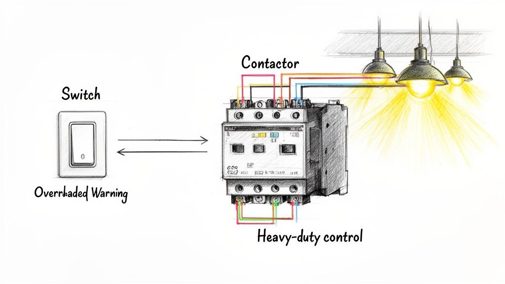
- Control Devices: These are the brains telling the contactor's coil (terminals A1 and A2) when to pull in. This could be as simple as a manual start/stop station or something more complex like a timer, photocell, or networked occupancy sensor.
Choosing the right parts isn't just about volts and amps. In gritty industrial environments, you have to think about the NEMA rating of your enclosure and components. It's all about protecting the gear from dust, moisture, and chemicals. A NEMA 4X rating, for instance, is a must in food processing plants where high-pressure washdowns are part of the daily routine.
The demand for these systems isn't slowing down. The global lighting contactor market was valued at USD 683.7 million back in 2017 and was on track to hit USD 1,111.0 million by 2023. This growth really highlights how critical reliable contactor wiring diagrams lighting solutions are for modern industrial facilities.
Key Component Selection Checklist
Getting the component specs right is make-or-break for any project. Here's a quick cheat sheet to help you plan your next lighting control panel.
| Component | Primary Function | Key Selection Criteria (Voltage, Amperage, etc.) | Common Industrial Use Case |
|---|---|---|---|
| Contactor | Switches high-power lighting load | Amperage rating, coil voltage, number of poles (2, 3, or 4) | Controlling banks of high-bay LED fixtures in a warehouse. |
| Circuit Breaker | Overcurrent and short circuit protection | Amperage rating, interrupting capacity, voltage | Main disconnect and safety for the entire lighting circuit branch. |
| Control Transformer | Steps down voltage for the control circuit | Primary/secondary voltage, VA rating | Converting 480V AC to 120V AC for a start/stop station. |
| Timeclock | Automated, scheduled lighting control | Voltage, channel count, battery backup | Scheduling parking lot lights to turn on at dusk and off at dawn. |
This checklist should give you a solid foundation for pulling together a bill of materials that works right the first time.
Wiring Schematics for Single-Phase and Three-Phase Systems
Alright, you've got your components picked out. Now for the fun part: wiring it all up. This is where we bring your lighting system to life, and getting the power wiring right from the get-go is everything.
We’ll break down the two main power setups you’re going to run into out in the field: single-phase and three-phase. Each has its own quirks, but the fundamental flow of power—from protection to the final load—is the same across the board. The lessons I've learned building UL-compliant panels come down to this: do it right, do it safely, and make it last.
This flowchart shows the basic power path in any contactor circuit. Power flows from the breaker, through the contactor, and finally through the overload protection to the lights.
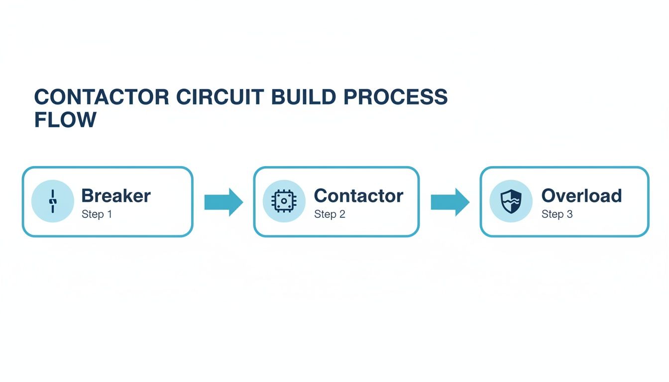
Keeping this sequence in mind helps you remember that every component has a specific job in controlling and protecting your lighting.
Single-Phase Lighting Contactor Wiring
Single-phase is what you'll find in most smaller commercial spots, workshops, or dedicated zones inside a bigger facility. We're usually talking about 120V or 277V, carried by two wires: a "hot" and a neutral.
When you pull up a contactor wiring diagrams lighting schematic for a single-phase job, the connections are pretty straightforward.
- Line (Hot) Conductor: This is the wire coming from your circuit breaker. It lands on the contactor's input terminal, which is almost always labeled L1.
- Neutral Conductor: This wire is the return path. It typically runs straight to the lighting load, often connecting through a neutral bus bar in your panel.
- Load Conductor: From the contactor's output terminal (T1), a wire goes out to the hot side of your lights.
- Ground: This one’s non-negotiable for safety. The equipment ground wire needs to be solidly connected to the metal chassis of the control panel, the contactor's ground lug, and the lighting fixtures.
Pro Tip from the Field: Always, and I mean always, size your wires based on the total amperage draw of your lights, following the National Electrical Code (NEC). Using undersized wire is one of the quickest ways to create a fire hazard. For a standard 20-amp lighting circuit, you should be using 12-gauge copper wire, period.
Picture a small machine shop. You might use a single-pole contactor to switch on all the 120V task lights above the workbenches. The hot wire from a 20A breaker lands on L1. The wire heading to the lights leaves from T1. When the coil gets energized, L1 and T1 connect, and the lights pop on. Simple and effective.
Three-Phase Lighting Contactor Wiring
Step into any large industrial facility, warehouse, or factory, and three-phase power is king. It’s the workhorse that delivers more power more efficiently, perfect for running heavy machinery and huge banks of lights.
Wiring a three-phase contactor means you’re wrangling three separate hot conductors—L1, L2, and L3.
The hookup is just as logical:
- Incoming Power (L1, L2, L3): Each of the three hot lines from your three-pole breaker connects to the matching input terminals on the contactor: L1, L2, and L3.
- Outgoing Power (T1, T2, T3): Power leaves the contactor from the output terminals—T1, T2, and T3. Each of these lines then feeds a different bank of lights. T1 might handle aisle one, T2 gets aisle two, and T3 powers aisle three.
This isn't just for neatness; it's fundamental to a stable system. The power-side principles are very similar to what you'd see in motor controls, and you can find more examples in this guide on a three-phase motor wiring diagram.
The Importance of Phase Balancing
Here's something I see rookies get wrong all the time: phase balancing. It just means you need to spread your lighting loads as evenly as possible across the three phases.
Let's say you're installing 90 new high-bay LEDs in a warehouse. A bad install would lump them all onto one or two circuits. A professional install wires 30 fixtures to T1, 30 to T2, and the last 30 to T3.
Why does this matter so much?
- Prevents Overloads: An unbalanced load makes one phase work way harder than the others. This can cause nuisance trips on the main breaker and puts a ton of stress on that one leg of the system.
- Ensures Stable Voltage: A balanced load keeps the voltage steady across all three phases. This means consistent light output and a longer, happier life for your fixture drivers.
- Maximizes Efficiency: A balanced three-phase system runs more efficiently, which adds up to real money saved on the power bill over time.
Seriously, failing to balance your phases is an amateur mistake that leads to flickering lights, fried equipment, and a whole lot of frustrating callbacks. Take a few extra minutes during the planning phase to map out your loads. It's the mark of a pro.
Designing Your Lighting Control Circuit Logic
Once the high-power wiring is buttoned up, it's time to tackle the brains of the operation: the control circuit. This is the low-voltage side where you decide how and when your lights actually do their job. A well-thought-out control strategy, laid out in your contactor wiring diagrams lighting schematic, turns a basic on/off switch into an intelligent, automated tool for your facility.
At its core, the control circuit has one simple job: to energize the contactor’s coil (at terminals A1 and A2). But the way it gets that job done can range from a dead-simple manual switch to a complex, sensor-driven network. This is where you bake in real efficiency, safety, and convenience.
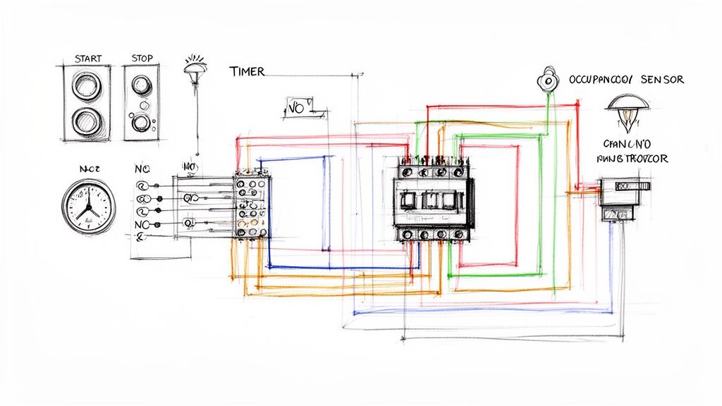
The Classic Start/Stop Pushbutton Circuit
The most fundamental control logic you’ll run into is the standard three-wire start/stop station. It's a classic for a reason—it’s reliable, intuitive, and safe. This setup brings two key players to the field: normally open (NO) and normally closed (NC) contacts.
- Start Button (NO): These contacts are open by default. When you push the button, you momentarily close the circuit, sending power to the contactor's coil.
- Stop Button (NC): These contacts are closed by default, letting current pass right through. Pushing it breaks the circuit, killing power to the coil and turning off the lights.
So, if the start button is just a momentary press, how do the lights stay on? The magic is in what’s called a "holding" or "latching" circuit. We use a spare normally open auxiliary contact right on the contactor itself, wired in parallel with the start button. The moment the contactor pulls in, that auxiliary contact closes. This creates a new path for electricity, bypassing the now-released start button and keeping the coil energized.
In the real world, the stop button’s NC design is a non-negotiable safety feature. If a wire to the stop button ever breaks or comes loose, the circuit is immediately interrupted, and the system fails to the "off" state. This fail-safe design is a cornerstone of safe industrial controls.
Automating with Timers and Photocells
Manual control is fine, but automation is where you find the real efficiency gains. Bringing timers and photocells into the mix is a common and powerful next step for industrial lighting.
A timeclock lets you schedule lighting around work shifts or facility hours. For example, you could program it to fire up the contactor for your main warehouse lights at 6:00 AM and shut it down at 6:00 PM, Monday through Friday. This one simple change stops you from relying on someone to remember to flip a switch, saving a ton on energy costs over time.
For outdoor security or parking lot lighting, a photocell is your go-to for dusk-to-dawn control. It acts as a light-sensitive switch in your control circuit. When the sun goes down and ambient light drops, the photocell's contacts close, completing the circuit to the contactor coil and turning the lights on. Come sunrise, the contacts open, and the lights switch off automatically.
Adding Intelligence with Occupancy Sensors
For maximum energy savings, nothing beats an occupancy sensor. These devices detect motion or presence in an area and tell the contactor what to do. They're perfect for spaces that see sporadic use, like storage rooms, loading docks, or individual work cells.
Wiring an occupancy sensor into your control circuit means the lights are only burning electricity when someone is actually in the room. In some applications, this can slash lighting energy consumption by up to 60%. The sensor is just an automated switch, closing the control circuit when it detects motion and opening it back up after a set time of inactivity.
This push for smarter controls is a huge market trend. Electrically held lighting contactors, which are a perfect match for these automated systems, have become cost-effective workhorses. The overall lighting contactor market was valued at USD 1.14 billion in 2023 and is set to grow, largely because of this widespread adoption of energy-conscious controls. You can dive deeper into the market dynamics and see how efficiency is shaping the entire industry.
Integrating with PLCs and Building Automation
For the most advanced control, you can tie your lighting contactor into a Programmable Logic Controller (PLC) or a central Building Automation System (BAS). This takes your lighting from a standalone system to a responsive component of your entire facility's operation.
In this kind of setup, the PLC or BAS is the master controller. The system can be programmed with complex logic, like:
- Turning on lights in one zone only when a specific machine in that area is running.
- Dimming lights during slow periods or when there's enough natural daylight.
- Sequencing the startup of different lighting banks to manage inrush current.
The wiring itself is often surprisingly simple. A low-voltage digital output from the PLC (usually 24V DC) gets wired straight to the contactor's coil (assuming you have a matching coil, of course). When the PLC program calls for lights, it sends a signal to that output, energizing the contactor. This level of integration gives you unparalleled control and diagnostic power, making your lighting system truly smart.
Meeting UL Standards and NEC Safety Codes
Getting the lights to turn on is one thing. Making sure they stay on—safely and reliably—is another challenge entirely. As a UL-certified panel shop, we don't just build systems that work; we build them to protect people and equipment, with safety and compliance baked in from the very first wire.
This isn’t just about checking a box for an inspector. Every single detail in your contactor wiring diagrams lighting schematic has to line up with established safety protocols. That means following the National Electrical Code (NEC) precisely and, for any panel assembly, strictly adhering to UL 508A standards. These aren't just guidelines—they are the law of the land for safe electrical work in the US.
Grounding and Conductor Sizing
You can't overstate the importance of proper grounding. It’s the single most critical safety feature in any electrical system, giving fault current a safe path to travel and preventing a metal enclosure from turning into a lethal shock hazard. Every non-current-carrying metal part, from the contactor frame itself to the fixture housings way out on the floor, needs a rock-solid connection back to the equipment ground.
Just as crucial is choosing the right wire size. The NEC has detailed tables that spell out the minimum wire gauge based on the circuit's amperage and the wire's temperature rating. Using an undersized wire is a recipe for a fire, plain and simple. It will overheat, melt its insulation, and eventually fail catastrophically.
We see one mistake out in the field all the time: installers forget to calculate for voltage drop on long runs. In a big warehouse, the distance from the panel to the last light can easily be hundreds of feet. That resistance adds up, causing voltage to sag, lights to dim, and components to fail prematurely. Always do the math and upsize your conductors to ensure the load gets the voltage it needs.
Component Ratings and Panel Layout
Every single component in your circuit—the breaker, the fuse, the contactor—has a specific voltage and amperage rating stamped on it. You have to select parts rated for the maximum potential load, not just the average. You can't put a contactor rated for 20 amps on a 30-amp circuit, even if the lights only pull 18 amps on a normal day. You build for the worst-case scenario.
How you arrange everything inside the control panel is just as important for safety and long-term reliability.
- Power and Control Separation: Keep your high-voltage power wiring physically separate from the low-voltage control wiring. Run them in different wireways or on opposite sides of the enclosure. This prevents electrical noise (EMI) from interfering with your control signals.
- Proper Ventilation: Contactors, transformers, and power supplies all generate heat. Your panel needs a way to breathe. Make sure there’s adequate ventilation—or even fans—to keep components from overheating and dying an early death.
- Clear Labeling: This is a non-negotiable. Every wire, terminal block, and component must be clearly and permanently labeled. It's a lifesaver during troubleshooting and makes maintenance faster and safer for the next person who has to open that panel.
Following these standards isn't just good practice; it's what the market demands. Commercial applications have always dominated the lighting contactor market, representing a multi-billion-dollar footprint in 2023. This trend is driven by the push for sophisticated, scalable lighting controls that meet tough energy codes. The total market, valued at USD 1.2 billion in 2024, is expected to climb to USD 2.1 billion by 2031.
Ultimately, safety is the top priority on any electrical job, big or small. Even for a simple home project, a guide to a ceiling fan remote wiring diagram with safety tips will stress these same core principles. To get a much deeper look at professional panel building, check out our guide on the best practices for industrial control panel design.
Common Questions About Lighting Contactor Wiring
Even with the best diagrams laid out on a cart, questions always pop up in the field. Let's tackle some of the most frequent challenges and uncertainties we hear from engineers and technicians when they're deep in a lighting control panel. These aren't textbook answers; they come straight from decades of designing, building, and troubleshooting industrial systems.
Can I Use a Motor Contactor for a Lighting Load?
This is probably the most common question we get, and the short answer is: maybe, but you have to be careful. A standard NEMA-rated motor contactor is a beast, built to handle the massive inrush current (inductive load) from a motor kicking on.
Lighting loads are a different animal. Modern LEDs and fluorescents with electronic ballasts have their own high initial inrush, but then they settle into a steady capacitive or resistive load. While a motor contactor is tough, it’s not always the right tool for the job. You can get away with it if it's properly oversized, but you risk premature contact wear or, even worse, the contacts welding themselves shut.
For peace of mind and guaranteed compatibility, stick with a contactor specifically rated for lighting or one with a general-purpose rating that covers your load type.
Why Is My Contactor Buzzing or Humming Loudly?
A slight, steady hum from an electrically held contactor is normal. That's just the sound of the AC electromagnet doing its job. But a loud, angry buzz? That’s a clear cry for help.
Here are the usual suspects:
- Low Coil Voltage: If the voltage hitting A1 and A2 is under the coil's rating, the magnet won't have enough muscle to pull the contacts in tight, causing chatter.
- Debris or Obstruction: You'd be surprised how a tiny metal shaving or a bit of grit between the magnet faces can keep it from sealing, creating that awful racket.
- Wrong Coil for the Job: Slapping a 120V coil into a 24V control circuit (or the other way around) will cause instant problems, from a loud buzz to a fried coil.
- Damaged Shading Ring: Inside an AC contactor, a small copper "shading ring" keeps the magnetic field stable. If it's cracked or missing, the contactor will chatter like crazy.
A buzzing contactor isn't just an annoyance; it's a warning sign that failure is right around the corner. That constant vibration will destroy the coil or the contacts. Don't ignore it—troubleshoot it immediately before it leaves you in the dark.
How Do I Choose the Right Coil Voltage?
This one is simple but critical: the coil voltage must match your control circuit voltage. It has nothing to do with the high-voltage power you're switching.
If your control circuit is fed by a transformer that steps 480V down to 120V, you need a contactor with a 120V AC coil. Period.
If you’re working with a modern PLC or automation system, your control logic is likely running on 24V DC. In that case, grab a contactor with a 24V DC coil. Mismatching the coil voltage is one of the fastest ways to let the magic smoke out of a brand-new component. Always double-check your control voltage before you order parts for your contactor wiring diagrams lighting project.
What Does the Auxiliary Contact Do?
Those small contacts on the side or top of the contactor—often labeled 13/14 (NO) or 21/22 (NC)—are the auxiliary contacts. They aren't for the main lighting power. Think of them as the contactor's low-voltage communication system, used exclusively for logic in the control circuit.
Here's what they're typically used for:
- Holding Circuit: Like we talked about earlier, a normally open (NO) contact is used to latch the contactor "on" after someone lets go of the start button.
- Status Lights: Wire a pilot light through an NO contact, and you've got an instant visual indicator showing when the main lights are on.
- Feedback to a PLC: An auxiliary contact can send a signal back to a control system, confirming that the contactor actually pulled in when it was told to.
Essentially, they give the contactor a voice to report its status back to the rest of the control system.
At E & I Sales, we don't just sell components; we provide the expertise to make sure your industrial systems are safe, compliant, and built to last. For help with your next project, from custom UL control panels to system integration, explore our services.