
At its core, a single-line diagram (SLD) is the electrical world's most effective shorthand. It uses a universal set of single-line diagram electrical symbols to map out the power flow in a system. Think of it as the master blueprint for an entire electrical installation, allowing engineers and technicians to grasp complex circuits at a glance—from the utility connection all the way down to a single motor—without getting bogged down by drawing every individual wire.
Decoding the Language of Electrical Schematics
A single-line diagram, often just called a one-line, offers a high-level, simplified view of an electrical system. Rather than cluttering the page with all three phases of an AC circuit, it condenses them into a single line. This elegant simplicity makes the diagram incredibly easy to read and is absolutely essential for everything from initial design and arc flash studies to everyday maintenance and troubleshooting.
For anyone working with industrial power systems, fluency in these core single-line diagram electrical symbols is non-negotiable. These graphical icons are the alphabet of our language, conveying vital information about every component and how it all connects. A well-drawn SLD gives you the complete picture, which is fundamental to working safely and efficiently.
The practical benefits of a good SLD are hard to overstate:
- Enhanced Safety: It's the go-to document for lockout/tagout (LOTO) procedures. With it, you can confidently identify and isolate every power source before a single tool is picked up.
- Operational Clarity: When something goes wrong, the diagram shows you exactly how the system is interconnected, making it invaluable for tracing faults or planning system upgrades.
- System Analysis: Engineers use SLDs as the foundation for critical power system studies, including short-circuit analysis, protective device coordination, and load flow calculations.
This guide is designed to be your comprehensive visual dictionary. We'll dive into the most common symbols you'll encounter, explain what they do, and show you how they're used in the real world—in motor control centers (MCCs), switchgear, and UL-listed control panels.
To get started, it helps to group the vast library of symbols into a few main categories. This table gives you a quick overview of the key players on any SLD.
Common SLD Symbol Categories and Their Functions
| Symbol Category | Primary Function | Example Components |
|---|---|---|
| Circuit Protection | Interrupt power flow during overcurrents or faults. | Circuit Breakers, Fuses, Relays |
| Transformers | Step voltage up or down between different parts of the system. | Power Transformers, Control Transformers |
| Conductors & Connections | Represent the path of power flow. | Cables, Busbars, Splices, Terminations |
| Switches & Disconnects | Manually connect or isolate circuits for operation or maintenance. | Disconnect Switches, Safety Switches |
| Loads | Consume electrical power to perform work. | Motors, Heaters, Lighting Panels |
| Metering & Instrumentation | Measure and display electrical parameters like voltage, current, and power. | Ammeters, Voltmeters, Power Meters |
Understanding these basic groupings is the first step. From here, you can start to recognize how these individual components come together to form a cohesive system on paper.
This graphic gives a great visual summary of some of the most fundamental symbols you'll see time and time again.
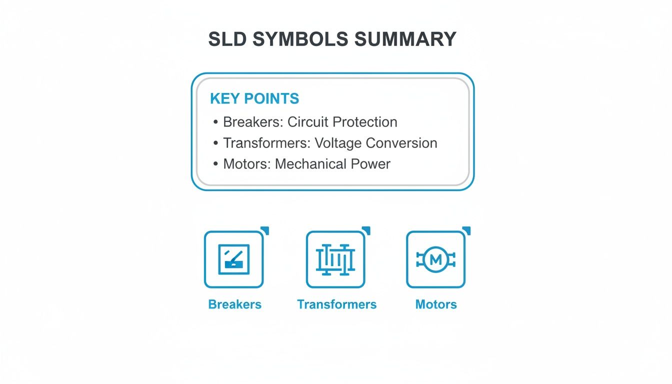
Each of these icons represents a core element: protection (breakers), power conversion (transformers), and the equipment doing the work (motors). These are the building blocks of almost any industrial SLD. Once you've got these down, you're well on your way to reading any electrical schematic that comes across your desk.
Why Standardized Electrical Symbols Are Critical
In any complex electrical system, clarity isn't just a convenience—it's the bedrock of safety and efficiency. Standardized single line diagram symbols electrical act as a universal language, wiping out the dangerous guesswork that leads to accidents. They ensure that an engineer in Tulsa and a technician in Berlin can look at the same schematic and understand the exact same story.
Think about it this way: a technician needs to perform emergency service on a critical motor control center (MCC). If the diagram uses some proprietary, non-standard symbols, they might mistake a circuit breaker for a simple disconnect switch. That one little mix-up could lead to them trying to open a circuit under a massive fault, triggering a catastrophic arc flash, destroying equipment, and causing severe injury.
Promoting Safety and Global Collaboration
This is why universal standards from bodies like ANSI (American National Standards Institute) and the IEC (International Electrotechnical Commission) are absolutely non-negotiable. For any company that takes safety and operational excellence seriously, these standards are the rule. Global OEMs and EPC firms, in particular, rely on them to allow their international teams to collaborate without a hitch, making design, review, and commissioning a much smoother process.
The whole concept of standardized symbols was a massive leap forward in engineering. It was pioneered by organizations like the IEC, IEEE, and ANSI to prevent the exact kind of chaos and danger that inconsistent drawings create. You can learn more about the history of electrical symbols and their development to see how far we've come.
A universally understood SLD is the first line of defense against electrical hazards. It ensures that every person interacting with the system, from the design engineer to the field technician, has a clear and unambiguous understanding of its configuration and potential risks.
Ensuring Compliance and Maintainability
Beyond the immediate safety concerns, sticking to these standards is essential for the long-term health of a system. For instance, if you're building UL-listed control panels, using the correct symbology is a fundamental requirement to get certified and pass inspection.
Years down the road, when that same facility undergoes a safety audit or needs a modification, that standardized documentation is what makes the job possible. It's a reliable, lasting record that future teams can trust. Without this common language, every service call or upgrade turns into a risky, time-consuming exercise in reverse-engineering.
Understanding Power Distribution and Conversion Symbols
Every single-line diagram starts with the power source. Think of these symbols as the very top of the electrical food chain, showing exactly where the power comes from and how it's converted for everything downstream. These are the foundational symbols you need to get right, as they set the stage for tracing the flow of energy from the grid all the way to a motor.
The most common starting point you'll see is the Utility Connection or Power Grid symbol. This little icon marks the exact point where the utility hands off power to the facility. You’ll almost always see it annotated with critical details like the incoming voltage and, just as importantly, the available fault current. That fault current number is a non-negotiable piece of information for any serious power system study.
Right after the utility feed, you're almost guaranteed to find a transformer. The transformer symbol is probably one of the most classic and recognizable single line diagram symbols electrical engineers work with daily.
Transformers: Stepping Voltage Up or Down
A transformer is a beautifully simple static device that uses electromagnetic induction to pass energy between circuits, usually to change the voltage. The standard symbol shows a couple of coils, but there are tons of variations that give you more detail—things like the winding connections (Delta or Wye) or the physical build (liquid-filled or dry-type).
- Step-Down Transformers: These are the workhorses in most industrial and commercial settings. They take high utility voltages, like 13.8kV, and knock them down to a usable level for equipment, typically 480V.
- Step-Up Transformers: As the name implies, these do the opposite. You'll find them where power is being generated, like at a plant with its own generators, to boost the voltage for efficient transmission over long distances.
The layout of a substation and where these transformers are placed is a whole discipline in itself. If you want to dive deeper, take a look at our guide on electrical substation design.
Generators and Busbars
If a facility has its own backup or primary power, a Generator Symbol will be on the diagram. It's usually just a circle with a "G" inside. This tells you there's an on-site source, like a diesel generator. Key specs like its kVA rating, voltage, and phase should always be noted right next to it.
A busbar is the main distribution hub inside a piece of switchgear or a motor control center. It’s basically a thick metal bar that provides a common connection point, letting multiple circuits tap into the same power source.
On an SLD, the busbar symbol is just a thick, heavy line, either horizontal or vertical. It’s simple but incredibly important. You'll see all the individual circuits branching off from this central bus. The busbar's voltage and amperage rating are crucial details that must be on the diagram to confirm it can handle the total load. Together, these source and distribution symbols form the bedrock of the entire diagram.
Identifying Circuit Protection and Switching Symbols
Think of protective and switching devices as the traffic cops and security guards of your electrical system. The symbols we use for these on a single-line diagram are absolutely critical for understanding how to isolate equipment for maintenance, kill power during a fault, or simply manage load connections. Getting these symbols right isn't just good practice; it's a fundamental skill for keeping everyone safe on the job.
These symbols are the bedrock of operational safety. They tell you exactly where and how a circuit can be de-energized. If you mistake a disconnect switch for a breaker, you could find yourself in a very dangerous situation, trying to open a device that simply isn't rated to handle the load.
Fuses and Disconnect Switches
Let's start with the basics: fuses and disconnect switches. These are your go-to components for simple protection and isolation. A fuse is a one-and-done overcurrent device; it's designed to melt and open the circuit when something goes wrong. On the other hand, a disconnect switch gives you a clear, visible air gap for isolation, but you should never open one under heavy load or fault conditions.
- Fuse Symbol: You'll typically see this as a rectangle with a line running through it. Sometimes that line has a slight "S" curve. The most important annotation here is its amperage rating (e.g., 100A).
- Disconnect Switch Symbol: This one is pretty intuitive—it’s a break in the line with a hinged segment that shows it can swing open. It always needs to be annotated with its voltage and amperage ratings.
In the real world, you'll often find these combined into a single unit called a fused disconnect switch, which handily provides both isolation and overcurrent protection.
Circuit Breakers and Contactors
Now for the dynamic duo of switching and protection: circuit breakers and contactors. They might look similar at a glance on an SLD, but their jobs are worlds apart. A circuit breaker is your automatic safety net, designed to trip during a fault. A contactor is more like a light switch, just a much bigger one, controlled remotely by a separate, low-power signal.
Expert Tip: Never confuse a breaker and a contactor on a diagram. A breaker is built to safely interrupt a massive fault current, potentially thousands of times its normal rating. A contactor is only meant to switch a load on and off under normal conditions. Using it to break a fault is a recipe for disaster.
Circuit Breaker Symbol: The classic symbol is a small square box right on the line. You might see additional markers to indicate special types, like draw-out breakers, which are standard in switchgear and motor control centers. Knowing the specific model, like an ABB circuit breaker, helps you understand its exact capabilities.
Contactor Symbol: A contactor is usually shown as two small parallel lines breaking the main power line, which represent its open contacts. This symbol is almost always paired with a coil symbol elsewhere on the control schematic to show how it's activated.
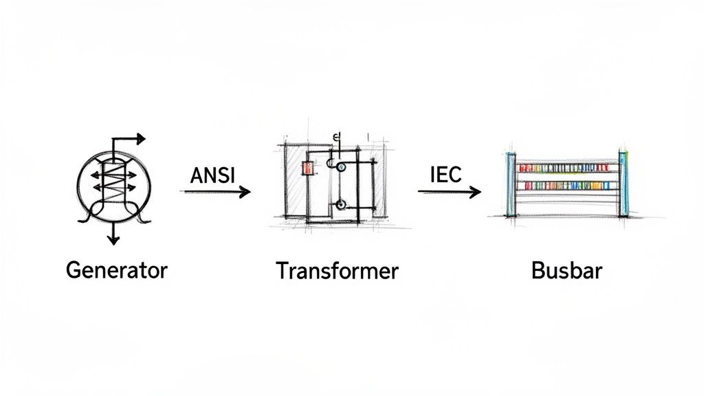
As you work with different drawings, especially from international projects, you'll notice differences between ANSI (American) and IEC (European/International) standards. Their symbols for the same device can be quite different, so it's vital to know which standard you're looking at.
ANSI vs IEC Common Symbol Comparison
When you're looking at schematics from different parts of the world, knowing the local dialect of symbols is key. The table below gives you a quick visual cheat sheet for some of the most common protection devices, comparing how they're drawn under ANSI and IEC standards.
| Component | ANSI Symbol (Image/Description) | IEC Symbol (Image/Description) | Key Difference |
|---|---|---|---|
| Circuit Breaker | A small, simple square on the line. | A square containing an 'X' or other markers. | The IEC symbols tend to pack more functional detail into the main shape itself. |
| Fuse | A rectangle with a line passing completely through it. | A simpler rectangle, where the line doesn't extend past the ends. | The ANSI symbol is a bit more pictorial, looking more like a cartridge fuse in its holder. |
| Disconnect Switch | A break in the line with a hinged segment, showing the motion. | A simple T-shaped symbol on the line indicating an isolation point. | ANSI focuses on visualizing the physical action of opening the switch. |
Pay close attention to these distinctions. Mixing them up can lead to a fundamental misunderstanding of how a system is designed to operate and be serviced safely.
Mastering Motor Load and Control Symbols
In any industrial plant, motors are the real workhorses. On a single-line diagram, their symbols are more than just placeholders; they're the core of the whole operation. These single line diagram symbols electrical representations tell you everything you need to know about power demands, control schemes, and the settings for protective gear.
The most common symbol you'll see is a simple circle with an "M" inside. That’s your motor. But the symbol alone isn't the whole story. You'll almost always find critical notes right next to it, like its horsepower (HP) or kilowatt (kW) rating, full-load amps (FLA), and operating voltage. Having that info right there is crucial for everyone, from the engineers designing the system to the technicians troubleshooting a breakdown on the floor.
Differentiating Motor and Load Types
While the basic "M" in a circle is a good start, a really well-drawn SLD gives you more detail. Different symbols can tell you exactly what kind of motor you're dealing with or distinguish it from other major electrical loads.
- Three-Phase AC Induction Motor: This is your standard, go-to symbol—a circle with an "M." It's the most common type you'll encounter in the field.
- DC Motor: This one also gets an "M" in a circle, but you'll see extra markings to show the armature and field windings. It’s a clear visual cue that you're looking at a direct current system.
- Variable Frequency Drive (VFD): A VFD isn't a motor, but it controls one. Its symbol, usually a rectangle with a sine wave and an arrow, sits on the line right before the motor. This immediately tells you the motor's speed is adjustable.
Take a look at this simple diagram. It perfectly shows the power path from the utility source, through the necessary protective devices, and down to the three-phase motor at the end.
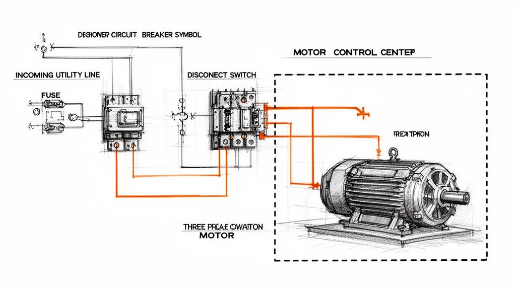
You can see how the fuse and disconnect switch protect the motor load. This fundamental relationship between protection and the load is the basis for every SLD you'll ever read.
Connecting Loads to Control Systems
The motor symbol is just one part of a bigger picture. A useful SLD has to show how that motor is controlled and protected. You'll see lines connecting it back to the key components in its starter, which is especially important when you're looking at diagrams for a large piece of machinery or a whole Motor Control Center (MCC).
Every motor symbol on a diagram tells a story about its role in the larger system. It's linked to an upstream circuit breaker for fault protection, a contactor for on/off control, and an overload relay to protect against thermal damage. Understanding these connections is essential for safe and reliable operation.
For example, if you trace the line from the motor symbol, you'll work your way back through an overload relay (often shown as a curved line under a bimetallic strip symbol), then to a contactor, and finally up to a circuit breaker or fuse. This sequence lays out the complete power and protection path—an absolutely indispensable map for any engineer or technician.
Understanding Instrumentation and Protective Relays
A good single-line diagram does more than just trace the path of power. It has to show how the system is being watched and, critically, how it's protected from a catastrophic failure. This is where symbols for instrumentation and protective relays enter the picture. Think of these specialized single line diagram symbols electrical as the intelligence layer that keeps expensive assets like transformers and big motors from destroying themselves.
Instrumentation symbols are the easy ones. They represent the meters that give you real-time data. You'll see a circle with an "A" for an Ammeter (measuring current) or a "V" for a Voltmeter. These are the gauges operators need to confirm system conditions at a glance.
Protective relays, on the other hand, are the system's brain. These devices are purpose-built to spot abnormal conditions—overcurrent, short circuits, ground faults—and then automatically tell a circuit breaker to open. This all happens in milliseconds to isolate the problem.
Decoding ANSI Device Numbers for Relays
On North American drawings, you'll see protective relays identified by a standard set of numbers from ANSI/IEEE Standard C37.2. Each number points to a very specific protective function, and you'll find it inside the relay's circle symbol on the SLD. If you want to understand a modern protection scheme, you have to know these numbers.
Here are a few of the most common ANSI device numbers you'll run into constantly:
- 50 Instantaneous Overcurrent: This is the system's emergency brake. It trips with no intentional delay the second the current shoots past a high setpoint. Its whole purpose is to provide lightning-fast protection against major short circuits.
- 51 AC Time Overcurrent: You can think of this as the "timed overcurrent" relay. It waits for a specific, coordinated amount of time before tripping. This function protects against those sustained overloads that cook equipment over time.
- 87 Differential Protection: This is a highly sensitive and fast-acting scheme. The relay compares the current going into a piece of equipment (like a transformer or generator) with the current coming out. If they don't match, it means there’s a fault inside the equipment, and the relay trips immediately to limit the damage.
You'll very often see a "50/51" designation on an SLD. This just means a single modern, microprocessor-based relay is handling both the instantaneous (50) and time-overcurrent (51) jobs. It's a standard combination in today's digital relays.
Single-line diagrams are the universal language for mapping out complex electrical systems everywhere, from factories to power plants. Engineers and technicians depend on dozens of these standard symbols to communicate everything from transformers and breakers to the sophisticated protection systems we've just discussed. For a broader overview of their role, check out Wikipedia's page on single-line diagrams.
Ultimately, these relay symbols are what let you verify that a system isn't just up and running, but is genuinely safe and built to withstand faults.
How to Annotate Single Line Diagrams Effectively
The symbols on a single-line diagram are just the starting point. It's the annotations—the notes and data—that turn a basic drawing into a working document that’s actually useful for engineers, electricians, and maintenance staff. A symbol without data is just a picture; a symbol with the right data is a tool.
Think about it this way: a circuit breaker symbol tells you what it is, but an annotation tells you its frame size, trip rating, and interrupting capacity. That’s the critical detail you need for everything from commissioning and troubleshooting to performing an arc flash study. Getting the annotations right is non-negotiable for safety and functionality.
Essential Annotation for Key Components
To create a truly professional SLD, you have to include specific details for the major equipment. This isn't just good practice; it's what makes the diagram a reliable source of truth for anyone who needs to work on that system.
Here are the must-haves for common single line diagram symbols electrical components:
- Transformers: Always specify the kVA rating, primary and secondary voltages, the winding connection (like Delta-Wye), and the percent impedance (%Z).
- Circuit Breakers: You absolutely need the ampere frame (AF), ampere trip (AT), and the short circuit interrupting capacity (AIC or kAIC).
- Motors: Be sure to note the horsepower (HP) or kilowatt (kW) rating, full load amps (FLA), and the operating voltage.
- Cables and Wires: Detail the conductor size (AWG or kcmil), material (copper is standard, but you'll see aluminum), insulation type, and how many conductors run per phase.
An SLD is more than just a drawing; it’s a core piece of technical documentation. For more on the bigger picture of documentation, you might find this guide on creating better technical documentation helpful. It reinforces how clear, detailed information turns a good drawing into great project documentation.
A well-annotated diagram is a proactive safety tool. It equips technicians with the precise information they need to verify equipment ratings and perform lockout/tagout procedures correctly, significantly reducing the risk of accidents.
Finally, a simple but powerful habit is to cross-reference other relevant drawings. Add notes pointing to panel schedules, control schematics, or equipment layout plans. This connects the SLD to the rest of the documentation set, making it much easier for someone to navigate a complex project and track down issues when something goes wrong.
Frequently Asked Questions About SLD Symbols
Even after you've got a handle on the individual symbols, real-world questions always pop up when you're in the field. This section tackles some of the most common things we hear from engineers, technicians, and project managers who work with single-line diagrams every day.
What’s the Main Difference Between ANSI and IEC Symbols?
The biggest difference comes down to geography and graphic style. ANSI (American National Standards Institute) symbols are what you'll almost always see in North America. They often look a bit more like a simplified picture of the actual component.
On the other hand, IEC (International Electrotechnical Commission) symbols are the standard in Europe and most other parts of the world. These tend to be more abstract, using simple geometric shapes to represent components.
While they do the exact same job, a device can look totally different depending on the standard. A classic example is a circuit breaker: the ANSI symbol is a plain square, while the IEC version is a square with an 'X' inside. The first thing you should always do is check the drawing’s title block to see which standard is being used.
How Do I Read a Complex Motor Control Center SLD?
Don't get overwhelmed. The trick is to follow the power, starting from the top and working your way down.
- Find the Source: First, locate the main incoming power feed, its main protective device (breaker or fuse), and the main horizontal busbar that feeds the whole MCC.
- Follow the Vertical Bus: From the main bus, trace the power down a vertical bus to an individual motor starter unit, which everyone just calls a "bucket."
- Inspect the Bucket: Inside that specific unit, follow the circuit path through its local breaker or fuse, then the contactor, and finally the overload relay before it heads out to the motor.
Always pay close attention to the notes next to the motor symbol. That’s where you’ll find the critical data—horsepower (HP), voltage, and full-load amps (FLA)—which is essential for any kind of troubleshooting or maintenance work. Following this path from source to load is a fundamental skill for confirming protection schemes and carrying out safe lockout/tagout procedures.
Where Can I Find Downloadable Libraries of Electrical Symbols?
Most professional-grade CAD platforms for electrical design come packed with extensive symbol libraries right out of the box. Software like AutoCAD Electrical, EPLAN, and SolidWorks Electrical are the industry go-tos and have you covered for both ANSI and IEC standards.
You can also get symbols directly from the source. Major manufacturers like Schneider Electric, Siemens, and Rockwell Automation usually offer free, downloadable CAD blocks for their specific products on their websites. This is perfect when you need to show a particular model of a VFD or breaker. For more generic libraries, various online CAD repositories are also a great resource.
At E & I Sales, we specialize in turning complex schematics into functioning systems. From the motors and drives to the custom UL-listed control panels that run them, we provide the integrated hardware that brings your single-line diagrams off the page and onto the plant floor. Discover how our expertise can support your next project.