
Ever wondered how a massive chemical plant or a sprawling manufacturing facility runs with such clockwork precision? The secret isn't magic—it's process control and instrumentation.
Think of it like the cruise control in your car. You decide you want to go 65 MPH; that's your target, or Setpoint. The car's system constantly reads your actual speed from the speedometer—the Process Variable. If you start going uphill and slow down, the system detects this and automatically gives the engine more gas—the Control Variable—to get you back to 65 MPH. No hands, no feet, just a simple, continuous loop of measuring, comparing, and adjusting.
That same feedback loop is the beating heart of modern industry. From refining oil to bottling beverages, the goal is always to keep critical variables like temperature, pressure, or flow within a tight, optimal range. It’s all about guaranteeing product quality, boosting efficiency, and, most importantly, keeping operations safe.
The Three Core Elements of a Control Loop
Every automated control system, no matter how complex, boils down to three fundamental components. Get these, and you've got the foundation for understanding the entire field.
We can break down these core elements using our cruise control analogy, which makes it easy to see how they apply in a real-world industrial setting.
The Three Core Elements of a Control Loop
| Component | Industrial Example | Cruise Control Analogy |
|---|---|---|
| Process Variable (PV) | The current temperature inside a furnace. | The actual speed shown on your speedometer. |
| Setpoint (SP) | The target temperature of 150°C for a chemical reaction. | Your desired speed of 65 MPH. |
| Control Variable (CV) | The gas valve opening or closing to adjust the furnace's flame. | The throttle adjusting the engine's power. |
At the end of the day, a well-designed control loop is all about minimizing the difference—the "error"—between what's actually happening (the PV) and what you want to happen (the SP). This constant, tiny correction is what keeps massive, complex industrial processes stable and predictable.
Why This Matters in the Real World
This isn't just an academic exercise; it's big business. The global process automation and instrumentation market was recently valued between USD 74.45 billion and USD 81.05 billion, with major growth on the horizon. That boom is fueled by a relentless demand for better efficiency, tighter safety protocols, and lower operating costs across every sector imaginable.
Whether it’s getting the mix just right in a pharmaceutical batch or managing precise gas flows for heat treatment, as detailed in this piece on Process Control Heat Treatment Gas Analysis Solutions, the core principles remain the same.
By mastering the relationship between PV, SP, and CV, engineers and technicians can design and maintain the incredibly robust systems that power our world. If you're ready to see the hardware that makes this all possible, our guide to industrial controls and automation is the perfect next step. A solid grasp of these fundamentals is your key to understanding the more advanced strategies and tools that bring modern industry to life.
The Four Pillars of Industrial Instrumentation
Think of an industrial control system like a human nervous system. You have parts that sense the world, parts that send messages, a brain that makes decisions, and muscles that take action. This is the core idea behind all process control and instrumentation—an interconnected network of hardware that keeps things running smoothly.
These components aren't just a random collection of parts; they form a constant, looping conversation. The quality of each piece in that loop has a direct impact on how well the whole system performs. Let's break down the four essential pillars to see how they work together.
Sensors: The Senses of the Process
First up, and arguably the most fundamental, is the sensor. This is the device that's right there in the thick of it, acting as the system's eyes and ears. Its only job is to measure a specific physical property—what we call the Process Variable (PV)—and turn it into a signal the rest of the system can understand, usually an electrical one.
Picture a massive mixing tank in a food plant. A level sensor sitting in the liquid is constantly reporting how full that tank is. In a furnace, a thermocouple is measuring the heat. On a gas pipeline, a pressure sensor is keeping tabs on the force inside. Without good sensors, your control system is flying blind.
Transmitters: The Nerves Sending the Signal
Once the sensor gets a reading, that raw data has to travel to the system’s brain. That's where the transmitter comes in. It takes the tiny, often fragile signal from the sensor, cleans it up, boosts it, and converts it into a standardized signal that can survive a long trip through a noisy industrial plant without getting garbled.
The industry workhorse for this is the 4-20 mA analog signal. In this setup, 4 mA might mean the tank is empty, and 20 mA means it's full. This universal language ensures that a controller from one company can perfectly understand a sensor from another. The transmitter is the critical nerve fiber connecting the senses to the brain.
This concept map shows you exactly how that Process Variable, measured by the sensor and sent by the transmitter, fits into the bigger picture of the control loop.
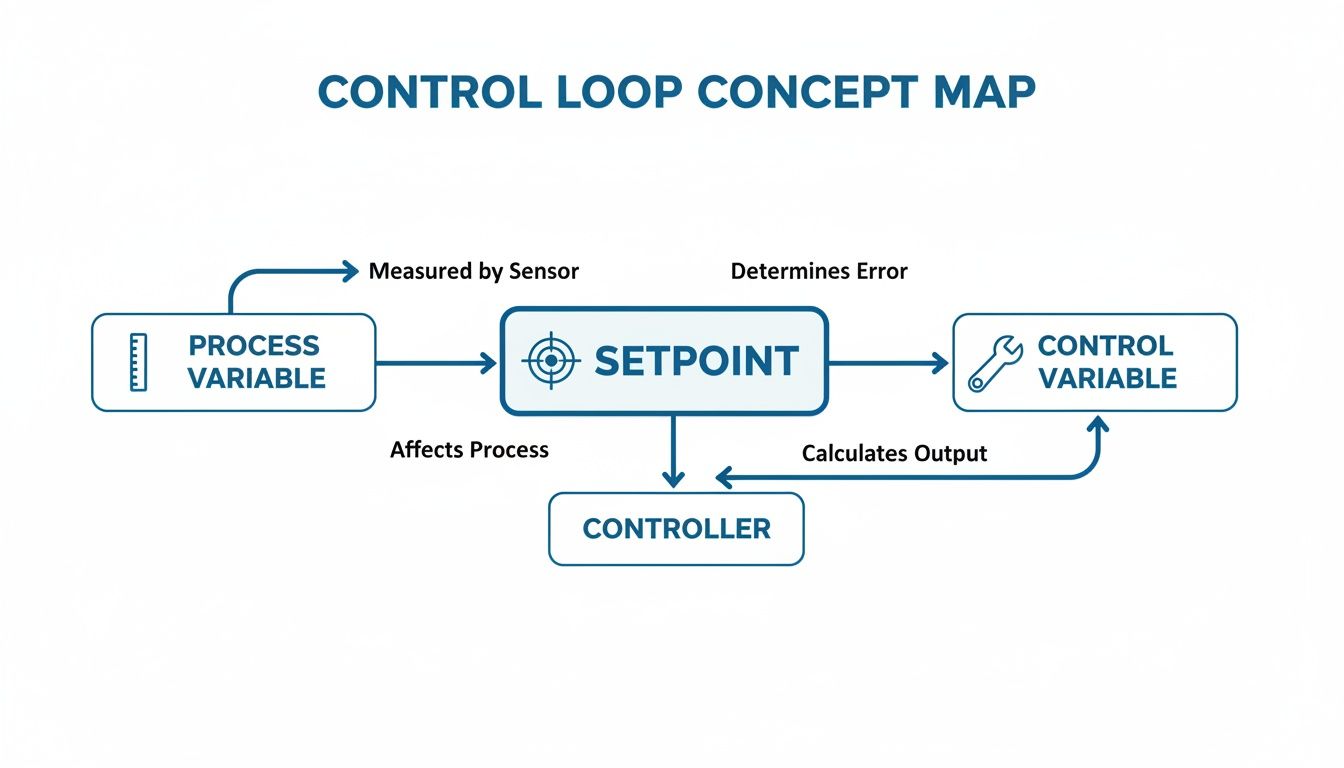
As you can see, it's a constant cycle: measure, compare, and correct.
Controllers: The Brain Making Decisions
The controller is the central command center of the whole operation. It receives that clean, standardized signal from the transmitter and does the most important job of all: it thinks. It takes the incoming Process Variable (PV) and compares it to the target value—the Setpoint (SP)—that an operator has programmed in.
Based on the difference, or "error," between what is happening and what should be happening, the controller calculates the right move. This "brain" is usually a Programmable Logic Controller (PLC) or a component within a larger Distributed Control System (DCS).
The controller is where all the logic lives. And getting the housing for this brain right is just as important as the logic itself, a topic we cover in our guide to industrial control panel design.
Final Control Elements: The Muscles Taking Action
A decision is worthless if you can't act on it. The last piece of the puzzle is the Final Control Element (FCE), which acts as the muscle of the system. It takes the command from the controller and physically changes something in the process to get that Process Variable back in line with the Setpoint.
This is where the rubber meets the road. The FCE is the part doing the actual work, and it can take many forms:
- A control valve that opens or closes a little more to adjust the flow of a liquid.
- A heating element in an oven that kicks on to bring the temperature up.
- A Variable Frequency Drive (VFD) that speeds up or slows down a motor running a pump.
Put them all together—Sensor, Transmitter, Controller, and Final Control Element—and you have a closed-loop system that is constantly measuring, comparing, deciding, and acting. This simple but powerful architecture is the bedrock of modern industrial automation, making sure processes run safely, efficiently, and with incredible consistency.
Choosing the Right Process Control Strategy
Once your physical hardware is in place, the game shifts from the "what" to the "how." The control strategy is the brain of the operation—it’s the logic your controller uses to hit and hold your target setpoint. Getting this right is what separates a system that constantly fights you from one that runs with clockwork precision.
The undisputed champion in the world of process control and instrumentation is PID control. It’s no exaggeration to call it the workhorse of automation; over 90% of industrial control loops rely on some flavor of it. Its real power comes from its elegant approach to managing a process by looking at the past, present, and future all at once.
PID Control: The Industry Standard
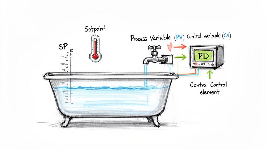
Let's use a simple, everyday task: filling a bathtub. You want the water to hit a specific level at just the right temperature. This familiar chore is a perfect way to understand the three parts of PID (Proportional-Integral-Derivative) control.
-
Proportional (P): This is your gut reaction. The tub is empty, so you crank the faucet on full blast. As the water level (your Process Variable) gets closer to where you want it (the Setpoint), you start to ease back on the handle. The P-action is a direct response to the current error—the bigger the gap, the bigger the reaction.
-
Integral (I): This part corrects for stubborn, lingering errors. Maybe your water pressure is a little low, and the tub is filling slower than it should. The I-action remembers this sluggishness and nudges the valve open just a bit more to make up for it, wiping out that small, persistent gap.
-
Derivative (D): This is all about looking ahead. As the water level surges toward your target, you start turning the faucet off before it gets there. Why? To keep it from overflowing. The D-action looks at how fast things are changing and pumps the brakes to prevent overshooting the target.
By carefully tuning these three elements, a PID controller delivers incredibly stable and reliable command over everything from motor speeds to the temperature inside a chemical reactor.
Advanced Strategies for Complex Challenges
While PID is a fantastic all-rounder, some processes have tricky variables that demand a more sophisticated game plan. For those tougher jobs, engineers bring in strategies like Cascade and Feedforward control for even tighter regulation.
Cascade Control: Manager and Worker Logic
Think about a situation where one variable has a huge, immediate impact on the one you actually care about. A great example is controlling the temperature of a product inside a jacketed reactor. Your main goal is the product temperature (primary variable), but it's directly affected by the jacket temperature (secondary variable).
Cascade control creates a smart "manager-and-worker" setup. The primary controller (the manager) watches the final product temperature. But instead of messing with the steam valve directly, it tells a secondary controller (the worker) what the jacket temperature should be.
This two-loop structure is brilliant at shutting down disturbances before they cause trouble. If steam pressure suddenly fluctuates, the nimble "worker" loop corrects the jacket temperature long before the product temperature even has a chance to drift.
Feedforward Control: Playing Offense Against Disturbances
Feedforward control is all about being proactive, not reactive. It works by spotting a potential disturbance before it hits your process and making a correction ahead of time.
Imagine you’re heating cold liquid as it flows into a tank. If that incoming flow suddenly doubles, a standard feedback controller won't do anything until it sees the tank's overall temperature start to drop.
A feedforward system, on the other hand, is much smarter:
- It measures the incoming flow rate (the disturbance).
- It instantly calculates how much more steam is needed for that extra liquid.
- It opens the steam valve wider at the exact same moment the flow increases.
This anticipatory move slashes the impact of the disturbance, keeping your process remarkably stable. For large-scale systems, understanding these different architectures is critical, a topic we dive into deeper in our breakdown of SCADA vs DCS. Ultimately, choosing the right logic—whether it's the foundational PID or a more advanced strategy—is the key to a responsive, efficient, and reliable control system.
How Control Systems Communicate with Each Other
A control system is only as smart as the information it can share. All the individual sensors, controllers, and actuators we’ve covered don't work alone—they're in a constant, high-speed conversation that keeps an entire facility running in perfect sync. This network is the nervous system of modern process control and instrumentation.
It wasn't always this easy. In the past, every single sensor and valve needed its own dedicated pair of wires running all the way back to a central control panel. Can you imagine the sheer amount of copper required for a plant with thousands of measurement points? It was an absolute beast to install, incredibly expensive, and a complete nightmare to troubleshoot. One bad wire could bring a critical process to a halt, sending technicians on a hunt through massive, identical cable bundles.
Thankfully, we've moved on. Today’s industrial communication is built on rugged, sophisticated digital networks, much like your office internet but designed to withstand the tough environment of a factory floor. These networks have dramatically cut wiring costs, simplified installations, and opened the door to powerful new diagnostic tools.
The Brains of the Operation: PLCs and DCS
At the heart of this communication web, you'll find the main controllers—usually a Programmable Logic Controller (PLC) or a Distributed Control System (DCS). These are the mission control centers, the air traffic controllers directing every signal in the plant.
PLCs are the sprinters, often used to manage individual machines or smaller, lightning-fast processes. They’re masters of discrete logic, like turning a conveyor belt on or off in a split second. A DCS, on the other hand, is the marathon runner, built to manage sprawling, continuous processes across an entire facility. It brings thousands of control loops together into a single, cohesive command center for operators.
Whether it’s a PLC or a DCS, these controllers act as the central hub, gathering data, running the control logic, and sending commands back out to the field. Their ability to speak the right "language" is what makes it all work.
The real magic is in the communication protocols. Think of them as the agreed-upon languages and grammatical rules that let different devices understand one another. Just like humans use English or Spanish, industrial devices use protocols to exchange information clearly and without fail.
Picking the right protocol is a huge decision. It affects everything from system speed and future scalability to how easily you can upgrade your equipment down the road.
Understanding Industrial Communication Protocols
Over the years, a whole zoo of protocols has emerged to solve different industrial challenges. While there are many out there, a few have become the undisputed industry standards because they're reliable, well-supported, and just plain work. Getting a handle on the differences between a workhorse like Modbus and a modern powerhouse like EtherNet/IP is crucial.
A quick look at the major players helps paint the picture. Each protocol was designed with a specific job in mind, and knowing their strengths is key to building a robust network.
Comparing Common Industrial Communication Protocols
| Protocol | Primary Use Case | Key Advantage |
|---|---|---|
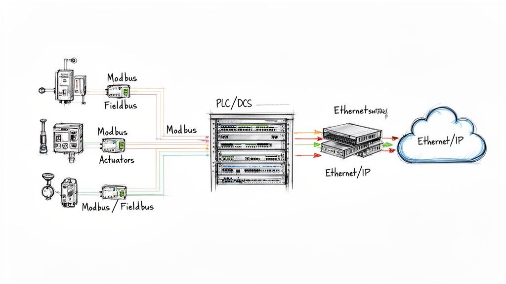
| Modbus | Simple device communication, connecting basic sensors/meters to a PLC. | Extremely simple, universally supported, and easy to implement. |
| Fieldbus (FOUNDATION, Profibus) | Complex process control, connecting "smart" instruments. | Allows two-way communication and advanced diagnostics over a single pair of wires. |
| EtherNet/IP | High-speed, plant-wide networking and enterprise integration. | High bandwidth, uses standard Ethernet hardware, and seamlessly connects the factory floor to business systems. |
Here's a breakdown of what that means in the real world:
-
Modbus: Developed way back in 1979, Modbus is the granddaddy of them all. It’s a simple, tough master-slave protocol where one device (the master) asks another (the slave) for its data. It’s not the fastest, but its simplicity makes it a rock-solid choice for basic device connections.
-
Fieldbus (FOUNDATION Fieldbus & Profibus): These protocols were a massive leap forward. They allowed multiple devices to share the same two wires, but more importantly, they introduced true two-way communication. Suddenly, a smart valve could send back not just its position, but detailed diagnostic data about its own health.
-
EtherNet/IP: This protocol uses the same technology that powers your office computers and the internet. EtherNet/IP brings incredible speed and bandwidth to the factory floor, allowing control data, diagnostics, and even corporate data to travel on the same network. It's the standard for modern automation for a reason.
These networks provide game-changing benefits. You're looking at drastically less wiring, faster project commissioning, and the power to diagnose a failing sensor from a control room miles away. Whether you're designing a single UL-listed control panel or an entire plant network, a solid grasp of these communication fundamentals is non-negotiable for building a resilient, scalable operation.
Meeting Critical Industry Standards and Compliance
In the world of process control and instrumentation, a clever design is only half the story. For a system to be safe, reliable, and insurable, it absolutely has to play by the rules—and those rules are written in the language of industry standards and codes.
Think of these standards not as suggestions, but as a critical framework. They ensure every component talks to each other correctly, installations won't create hazards, and your entire operation is compliant from day one. Navigating this landscape means getting familiar with a few key players.
You have organizations like the International Society of Automation (ISA), which sets the universal language for things like instrumentation diagrams (P&IDs). Thanks to them, an engineer in Texas and an engineer in Germany can look at the same drawing and know exactly what they’re seeing.
Then there’s the National Electrical Code (NEC), which is all about the hands-on, practical side of the job. It governs the safe installation of all electrical equipment, from how you route a cable to how you ground a panel. Following the NEC isn't just good practice; it's a legal requirement that inspectors enforce to prevent fires and electrical accidents.
The Gold Standard for Control Panels: UL 508A
While the ISA and NEC set the broad stage, the UL 508A certification puts a laser focus on one of the most vital parts of any system: the industrial control panel. This standard from Underwriters Laboratories is the undisputed benchmark for safety and quality in North America.
A UL 508A sticker on a control panel isn't just for show. It’s a declaration that the panel was designed and built to a strict, independently verified set of safety rules. It means every single component inside was chosen, sized, and wired correctly for its specific job.
Partnering with a UL 508A certified panel shop brings some serious, non-negotiable advantages to the table:
- Guaranteed Compliance: A UL-listed panel sails through inspections. It's pre-certified to meet national safety standards, which saves a massive amount of time, money, and headaches when the local Authority Having Jurisdiction (AHJ) shows up.
- Real-World Safety: The standard is all about the details that prevent disaster—things like proper component spacing to avoid overheating, correct short-circuit current ratings (SCCR), and wiring techniques that protect people from shock and arc flash.
- Reduced Liability: If something ever does go wrong, that UL 508A certification is documented proof that you did your due diligence. It shows a clear commitment to safety and is invaluable for any insurance claim or legal review.
Making sure your control panels are built to these standards is a foundational decision. It ensures the "brain" of your system is not just doing its job, but is fundamentally safe, reliable, and built for the long haul. For any serious industrial operation, UL 508A isn't a feature—it's a requirement.
The Future of Industrial Automation Technology
The world of process control and instrumentation is changing, and it's happening fast. We're moving beyond the simple feedback loops that have been the standard for decades and stepping into a new era of smart, predictive, and deeply connected operations. While the core job of measuring and correcting a process isn't going away, the tools we use to do it are becoming incredibly powerful. It’s all about getting industrial facilities ready not just for today, but for whatever comes next.
The engine driving this shift is the Industrial Internet of Things (IIoT). The best way to think about IIoT is that it gives a voice to every single component in your plant—every motor, every valve, every sensor. Instead of just getting a basic 4-20 mA signal, smart instruments can now pour out a ton of diagnostic data over industrial networks. This gives you a level of visibility into the health of your process that was unimaginable just a few years ago.
The Rise of Predictive Maintenance
All this new data unlocks one of the biggest game-changers for modern industry: predictive maintenance. For years, maintenance has been stuck in two inefficient modes. You either fix things after they break (reactive), or you replace parts on a rigid schedule, whether they need it or not (preventative). Both approaches cost you, either in surprise downtime or in wasted parts and labor.
Predictive maintenance flips that script completely. By analyzing live data from IIoT sensors—things like a tiny shift in a motor's vibration or a pump's temperature creeping up by a few degrees—these systems can spot the warning signs of failure weeks or even months out.
This lets your maintenance team switch from a "fail and fix" model to a "predict and prevent" strategy. Instead of getting a frantic call about a catastrophic failure at 3 AM, you can schedule the repair during planned downtime. That's a massive saving in both time and money.
AI and Advanced Process Control
But it’s not just about preventing failures; this new wave of tech is making the processes themselves smarter. Advanced Process Control (APC) systems use artificial intelligence and machine learning to fine-tune operations in ways a standard PID controller just can't match. An APC system can look at hundreds of variables at once, learning the incredibly complex relationships between them to make constant, tiny adjustments.
What does that mean for the bottom line? Huge improvements in:
- Yield: Squeezing the maximum amount of high-quality product out of your raw materials.
- Energy Efficiency: Cutting down power consumption by running equipment at its absolute sweet spot.
- Product Consistency: Tightening up variability to make sure every single batch meets spec perfectly.
This isn't just a niche trend; it's a market-wide shift. The entire process automation market is being reshaped by IIoT and advanced digital tools. Solutions built on predictive maintenance and APC are seeing the fastest growth, signaling that integrators have to move beyond just offering the same old services.
As we look ahead, bringing these technologies into the fold isn't just a simple upgrade—it's a fundamental change in how we think about running an industrial plant. Building systems ready for this connected future is the only way to stay competitive. For a deeper dive, you can learn more about AI enablement in industrial automation and robotics.
Got Questions? We've Got Answers.
When you're deep in the weeds of process control and instrumentation, a few key questions always seem to pop up. Whether you're comparing system architectures or justifying a component choice, getting straight answers is crucial. Here are some of the most common things we hear from engineers and technicians out in the field.
What’s the Real Difference Between a PLC and a DCS?
This is a classic. Think of it this way: a Programmable Logic Controller (PLC) is a sprinter, built for the fast, repetitive tasks of a single machine or a small, self-contained process. It's the go-to for controlling a conveyor system or a packaging line with lightning-fast, on/off logic.
A Distributed Control System (DCS), on the other hand, is a marathon runner. It’s designed to manage and orchestrate an entire plant, like a chemical refinery, with thousands of different control points all working together. It’s all about continuous control, providing a single, unified view for operators. While the lines are blurring a bit, the core idea holds: PLCs are for machine-level automation, and a DCS is for large-scale process orchestration.
How Do I Pick the Right Sensor for the Job?
Choosing the right sensor is everything—get it wrong, and nothing else matters. It really boils down to matching the tool to the specific task and environment.
- What are you measuring? Is it pressure, temperature, flow, level, or something else? Start here.
- What’s the environment like? Think about corrosive chemicals, extreme temperatures, high pressure, or constant vibration. The sensor has to survive where it lives.
- How accurate do you need to be? Getting a super-precise reading is great, but it costs more. Don't pay for accuracy you don't actually need for the process.
- What about the physical space? Will it be exposed to moisture? Does it need to be rated for a hazardous location?
Getting an expert opinion here is smart. It helps you find that sweet spot between performance, lifespan, and cost. You can avoid overspending on features you don’t need or, worse, having a cheap sensor fail and take your whole process down with it.
Why Does a UL 508A Certification Matter So Much?
Seeing that UL 508A sticker on a control panel is a big deal, and for good reason. It’s not just a label; it’s proof that the panel was built to rigorous, nationally recognized safety standards from Underwriters Laboratories. It’s the benchmark that inspectors and regulators look for.
A UL-certified panel means the right components were used, the wiring was done correctly, and all the essential safety features are in place. This is absolutely critical for protecting your team from shock and arc flash, preventing expensive equipment from getting fried, and making sure your facility is up to code. Simply put, it's a non-negotiable seal of safety and reliability.
At E & I Sales, we live and breathe this stuff. We specialize in designing and building UL-listed control panels that serve as the safe, reliable heart of industrial systems.