Designing an industrial control panel is far more than just stuffing a box with electrical gear. It's the art and science of creating the central nervous system for industrial machinery. You're specifying, organizing, and integrating everything from PLCs and VFDs to circuit protection—all within a single enclosure that has to meet incredibly strict safety and performance standards, namely UL 508A and the NEC.
Building Your Design Foundation
Think of the industrial control panel as the brain of any automated system. It takes commands from operators and inputs from sensors and turns them into precise actions. This could be as simple as starting a motor or as complex as running a multi-stage manufacturing line. Before you even think about mounting a component or pulling a wire, you have to build a solid design foundation. This means having a deep understanding of modern automation tech and the non-negotiable safety regulations that govern it all.
The evolution here has been nothing short of remarkable. We've moved from massive, clunky panels full of relay-based logic that were a nightmare to troubleshoot and offered zero flexibility. The real game-changer was the arrival of Programmable Logic Controllers (PLCs) back in the 1970s. Suddenly, we could create compact, programmable, and incredibly efficient automation systems that gave us unprecedented control and precision.
That shift from mechanical to digital is what defines modern panel design. Today's panels are sophisticated control hubs. They demand a systematic design approach to guarantee they are safe, reliable, and easy to maintain for years to come. This is where regulatory standards become your most valuable tool.
The Role of UL 508A and NEC
You absolutely must know the key standards that govern this work. In North America, almost every industrial control panel design is built on two pillars:
-
UL 508A (Standard for Industrial Control Panels): This is your playbook for building the panel itself. It lays out the specific requirements for everything—component selection, wiring methods, enclosure ratings, and calculating the critical Short-Circuit Current Rating (SCCR). When you see a UL 508A certification mark on a panel, it's a clear signal that it was built to these tough safety standards.
-
NEC (National Electrical Code), particularly Article 409: While UL 508A tells you how to build the panel, the NEC tells you how to install it in the field. It dictates how the panel connects to the building’s electrical system, ensuring proper overcurrent protection and safe integration with the rest of the facility.
Here's a simple way to think about it: UL 508A provides the specs for building a safe car, while the NEC gives you the traffic laws for driving it on the road. You need both to get from point A to point B without any disasters.
These standards are a roadmap, not a roadblock. They represent decades of collected wisdom, all aimed at preventing electrical hazards and equipment failures. When you build these principles into your design from day one, you make smarter decisions, and your final product isn't just functional—it's fundamentally safe.
These same principles scale up to much larger assemblies. For a closer look at how they apply in bigger systems, check out our guide on what is a motor control center. A well-designed panel, built on this foundation, is simply better—it’s easier to troubleshoot, safer for the people working around it, and more reliable over its entire lifecycle.
Your Strategic Design and Planning Workflow
A top-tier industrial control panel design doesn't just happen. It doesn’t start with picking parts or drawing schematics. It starts with a conversation. Skipping this critical discovery and planning stage is the single biggest reason I see projects go off the rails—leading to expensive rework, blown deadlines, and panels that just don't cut it in the real world.
First things first, you need to nail down the absolute scope of the project. This is way more than just "we need to control a motor." You have to get in there and talk to the people who will actually use and maintain this thing—the operators, the maintenance crew, the plant managers. What exactly is this machine supposed to do? What’s the full sequence of operations? How are people going to interact with it? Getting these answers down on paper gives you a functional specification that acts as your north star for the entire design process.
At the same time, you need to be a bit of a detective about the environment where the panel will live. A panel sitting in a clean, climate-controlled room has a completely different set of needs than one getting blasted in a washdown area or baking in a facility with high ambient heat. Things like dust, moisture, corrosive chemicals, and temperature fluctuations will dictate your choices for the enclosure, components, and any cooling you might need.
The way we approach panel design has evolved dramatically over the years, moving from simple relay logic to the sophisticated, standards-driven process we have today.
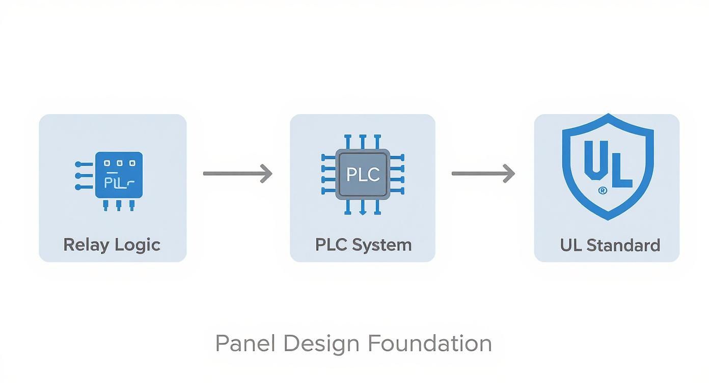
This journey shows that modern design isn't just about making something work; it's about making it safe and compliant. And in our world, UL standards are the benchmark for quality and safety.
Developing the Bill of Materials
Once the scope is crystal clear, you can start building out a preliminary Bill of Materials (BOM). The BOM is your master list of every single part going into that panel—from the big-ticket items like the PLC and power supply right down to the last terminal block and wire label. A detailed, accurate BOM is the foundation for getting a good quote, ordering parts, and building the panel correctly.
A rookie mistake is to create a BOM with vague descriptions. Don't just write "24VDC Power Supply." Get specific. Put the exact model number, the amperage, and any required certifications. This level of detail is what prevents sourcing headaches and ensures every part you order is right for the job.
Think of your BOM as a living document in the early stages. As you hash out the electrical schematic and run your calculations, parts will inevitably be added, swapped, or removed. Keep it organized in a spreadsheet or a dedicated design tool to track changes and avoid confusion.
Critical Power and Safety Calculations
Before you even think about finalizing your component list, there are two calculations you absolutely must perform: the power load analysis and the Short-Circuit Current Rating (SCCR).
-
Power Load Calculation: Tally up the power consumption (in watts or VA) for every single component in the panel—the PLC, I/O modules, relays, HMI, you name it. Then, add a healthy safety margin of at least 20-25%. This buffer is non-negotiable. It covers inrush currents when things power up and gives you a little wiggle room for minor additions down the road without having to re-engineer the whole power system.
-
Short-Circuit Current Rating (SCCR): This is, without a doubt, the most critical safety calculation you'll do. The SCCR tells you the maximum fault current a panel can handle without turning into a fireball. The overall panel's SCCR is only as good as its weakest link—the lowest-rated component in the power circuit. This calculation is a core requirement of UL 508A. It forces you to look at the entire power path and make sure every component is either rated for the available fault current or is properly protected. For a closer look at the components that play a role here, our guide on the protection of motors breaks down how to select the right circuit breakers and fuses. Skipping the SCCR calculation isn't just bad practice; it's a serious safety violation with potentially catastrophic consequences.
By being methodical and disciplined during this planning phase, you're building a rock-solid foundation. You’re ensuring the final panel won't just work, but it will be safe, compliant, and easy to maintain for years to come. That upfront strategic investment always pays for itself.
Choosing the Right Components for Your Panel
Picking the right hardware is where your design really starts to come alive. This isn't just about matching part numbers to a schematic; it’s about making smart trade-offs between performance, cost, and the panel's long-term reliability. Every single component, from the steel enclosure down to the smallest terminal block, has a job to do for the panel's overall safety and function.
The market for this stuff is booming right alongside industrial automation. In fact, the global industrial control panels market hit about USD 15.67 billion in 2024 and is expected to climb to USD 23.45 billion by 2033. That kind of growth tells you just how much demand there is for well-built, dependable panels running smart technology. You can dig into these market trends over at DataHorizzon Research.
Selecting the Right Enclosure
Think of the enclosure as the first line of defense for all the sensitive electronics inside. Getting this choice right is absolutely critical, and it all comes down to where the panel is going to live. Your guide here will be the NEMA (National Electrical Manufacturers Association) ratings.
For instance, a panel that's going into a clean, air-conditioned control room might just need a NEMA 1 or NEMA 12 enclosure. These are perfect for keeping out dust and the occasional light drip.
But what if that same panel is heading for a washdown area in a food processing plant? You're going to need something way tougher. A NEMA 4X stainless steel enclosure is the go-to choice here, built to handle high-pressure water jets and resist the corrosive bite of industrial cleaning chemicals. If you try to skimp with a lower-rated box in that environment, you're just asking for component failure from moisture getting in. It won't take weeks.
Pro Tip: Don't forget about future access. Can a maintenance tech actually get into this thing easily? Think about how the door swings and what kind of clearance you have. A badly placed enclosure door can turn a simple troubleshooting task into a nightmare.
Brains of the Operation: The PLC and HMI
At the core of nearly every modern panel is the Programmable Logic Controller (PLC). The one you choose really depends on how complex the machine is.
- For simple machines: A compact or "brick" PLC with a fixed number of inputs and outputs (I/O) is often the perfect fit. They're cost-effective and a breeze to program for basic, repetitive tasks.
- For complex systems: A modular PLC is the only way to fly. It lets you snap on different I/O modules—digital, analog, communication cards—as you need them. This gives you incredible flexibility to scale the system up or down later.
The Human-Machine Interface (HMI) is the operator's window into what the machine is doing. This choice is usually a tug-of-war between budget and features. A simple text display might be fine for basic start/stop functions, but a full-color graphical touchscreen gives you so much more—rich diagnostics, clear alarming, and a far more intuitive user experience.
Power and Protection Components
The components that distribute power and protect your circuits are the bedrock of a safe, reliable panel. This is an area where the UL 508A standard is particularly strict, and for good reason.
A frequent decision you'll face is whether to use a Miniature Circuit Breaker (MCB) or a Molded Case Circuit Breaker (MCCB) for the main power disconnect.
- MCBs are your workhorses for lower-amperage branch circuits, typically anything under 100A. They’re compact and economical for protecting individual loads.
- MCCBs are the heavy hitters, designed for higher amperage and much greater interrupting capacity. This makes them the right choice for main disconnects where the available fault current could be dangerously high.
When you get to devices like Variable Frequency Drives (VFDs), sizing is everything. You can't just look at the motor's horsepower and full-load amps (FLA). You have to consider the application's torque demands. A high-inertia load, like a massive industrial fan, needs a VFD that can muscle through that initial startup without tripping. To really get into the weeds on this, you can review the fundamentals in our article on variable frequency drive basics.
Finally, let's talk about the unsung hero: the power supply. A good rule of thumb is to always size your 24VDC power supply with at least a 25% capacity buffer over what you've calculated for your load. This extra juice handles inrush currents when devices power on and keeps the voltage steady for your sensitive PLCs and sensors, preventing those mysterious faults and dropouts that can drive you crazy.
Mastering Panel Layout and Thermal Management
You can spot a professionally designed control panel the second you open the door. It’s not just about cramming components into a box; it's about creating a clean, logical layout that makes life easier for everyone, from the assembler to the field technician trying to troubleshoot an issue years down the road.
A messy layout isn't just an eyesore. It’s a breeding ground for real problems, from electrical noise messing with your PLC to components cooking themselves to an early death.
The first and most important rule of a solid layout is segregation. You have to draw a clear line—physically—between different voltage levels. High-voltage power gear like VFDs, big contactors, and the main disconnect should all live together, usually clustered near the top of the enclosure where the main power feed comes in.
Then, give your low-voltage control components their own neighborhood. The PLC, I/O modules, and any communication devices need their space, far away from the noisy power circuits. This separation is your number one defense against electromagnetic interference (EMI), which can wreak havoc on sensitive control signals.
Strategic Component Placement and Wiring
Once you've mapped out your high- and low-voltage zones, the real art of placement begins. Start with the heavy hitters. Things like transformers and hefty power supplies should be mounted at the bottom of the enclosure to keep the panel stable and balanced.
Think about how electricity moves. Power should come in at the top, flow down through circuit breakers and fuses, and then head out to the loads. This top-to-bottom flow creates an intuitive visual path that makes wiring cleaner and troubleshooting a whole lot faster.
- Smart Wire Ducting: Don't just slap wire ducts on the backpanel. Place them deliberately to create clean, straight runs for your wiring. Stick to 90-degree turns and never, ever run wires haphazardly over the top of components.
- Give Them Space: Components need to breathe. Manufacturers list minimum clearance specs for a reason—it’s all about airflow and heat dissipation. Jamming components together is a surefire way to cause premature failures.
- Plan for the Future: This is a big one. Always leave at least 20-25% of your backpanel empty. That "white space" is gold when the customer needs to add another drive or a few more I/O points down the line. A panel that’s full on day one is a nightmare to upgrade.
A well-organized panel tells a story. A technician should be able to open the door and immediately understand the power flow and control logic just by looking at the layout. If it looks like a plate of spaghetti, you’ve made their job—and your own future troubleshooting—infinitely harder.
A Practical Guide to Component Spacing
UL 508A provides specific guidelines for spacing to prevent arcing and ensure safety. But beyond the bare minimum, giving components adequate room for airflow is just good engineering practice. This table offers a practical starting point.
| Component Type | Minimum Spacing from Other Components | Recommended Airflow Clearance (Top/Bottom) |
|---|---|---|
| Variable Frequency Drives (VFDs) | 2 inches (50 mm) | 4-6 inches (100-150 mm) |
| Power Supplies | 1 inch (25 mm) | 2-3 inches (50-75 mm) |
| PLCs and I/O Modules | 0.5 inches (12 mm) | 2 inches (50 mm) |
| Contactors and Relays | 0.5 inches (12 mm) | 1-2 inches (25-50 mm) |
| Circuit Breakers (MCPs/MCCBs) | 0.25 inches (6 mm) side-to-side | 1 inch (25 mm) |
Remember, these are general rules of thumb. Always defer to the manufacturer's installation manual for the most accurate clearance requirements, especially for high-heat components like VFDs.
Calculating and Managing Heat Load
Thermal management is easily the most overlooked part of panel design, yet it's absolutely critical for reliability. Every single component in that sealed metal box is generating heat. If you don't get that heat out, temperatures will skyrocket, leading to fried electronics and unexpected downtime.
It all starts with a heat load calculation. You need to add up the heat dissipated (in watts) by every major heat-producing component in the cabinet. The usual suspects are:
- Variable Frequency Drives (VFDs): These are often the biggest heat source. The manufacturer's datasheet is your best friend here; it will list the heat dissipation values.
- Power Supplies: A power supply’s efficiency rating directly tells you how much heat it’s kicking out. An 80% efficient supply, for example, is turning the other 20% of its input power straight into waste heat.
- PLCs and I/O Modules: One module might not be much, but a full rack of I/O cards can add up to a significant thermal load.
- Transformers and Relays: Even these simpler components contribute to the total heat inside the box.
Once you have your total internal heat load, you have to see if the enclosure can dissipate it on its own through its surface area. If your calculations show that the internal temperature will rise above the max operating temp of your components (a common limit is 104°F or 40°C), you need to get serious about active cooling.
For clean, relatively cool environments, a simple filter fan might be all you need. But if the panel is going into a hot, dusty factory, you'll need a closed-loop solution like an air conditioner or an air-to-air heat exchanger. This keeps the inside of your panel cool and clean, protecting your investment for the long haul.
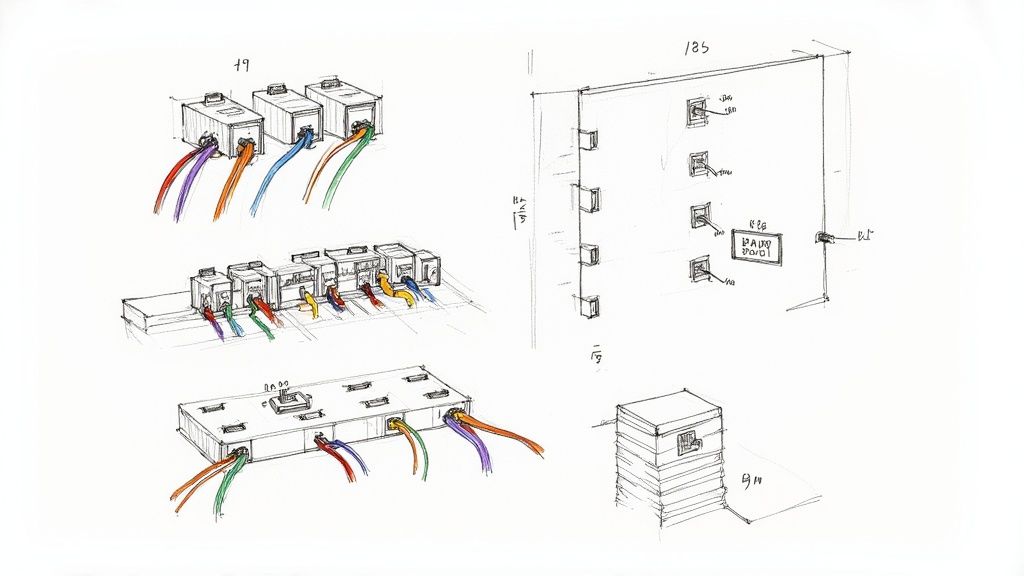
Finalizing Wiring, Labeling, and Documentation
This is where the rubber meets the road. A panel can have the best layout and top-of-the-line components, but if the final wiring, labeling, and documentation are sloppy, it’s a ticking time bomb for the maintenance team. Getting these finishing details right is what separates a merely functional panel from a professional, serviceable, and safe asset that will perform for years.
This level of detail isn't just a best practice; it's becoming a global expectation. It's interesting to note that the Asia Pacific region is now the fastest-growing market for industrial control panels, a trend driven by massive industrialization. This boom highlights a worldwide demand for high-quality, well-documented systems that can be supported long-term. You can dig into these global market dynamics and see detailed regional forecasts if you're curious about the trends.
Precision in Every Connection
Every single wire needs to be correctly sized, terminated, and clearly identified. This isn't about aesthetics—it's about safety and reliability.
Let’s start with wire sizing. You must select the conductor's gauge based on its ampacity, which is its ability to carry current without dangerously overheating. This is all laid out in NEC Table 310.16. Don't ever guess. An undersized wire is a serious fire hazard, plain and simple.
Proper termination is just as critical. When working with stranded wire, using ferrules is non-negotiable. A ferrule is a small metal tube you crimp onto the wire's end, which bundles all the fine strands together. This creates a solid, reliable connection point for a terminal block and prevents stray strands from causing shorts. It’s a simple step that ensures a durable, vibration-proof connection.
Adhering to Color Coding Standards
Think of a consistent wire color code as a universal language for electricians. It gives an immediate visual hint about a wire's function, which speeds up troubleshooting and cuts down on mistakes. While a specific project might have its own requirements, the industry generally follows a standard based on NFPA 79.
- Black: AC power conductors (L1, L2, L3).
- Red: AC control circuits (e.g., wires from a control transformer to devices).
- Blue: DC control circuits, usually 24VDC for PLCs, sensors, and the like.
- White (or Gray): Grounded AC current-carrying conductors, also known as the neutral.
- Green (or Green with a Yellow Stripe): Equipment grounding conductors, or earth ground.
Sticking to a strict color code is a hallmark of a professional build. Ten years from now, a technician should be able to open your panel and instantly grasp the basic electrical scheme just from the wire colors.
The Power of Clear Labeling
If color coding is the language, then labeling is the specific vocabulary. Every wire, terminal, and component needs a clear, durable, and unique label that matches the electrical schematics perfectly. If a wire is labeled "201A" on the drawing, it had better be labeled "201A" in the panel.
This is where investing in a quality thermal transfer label printer really pays off. They produce crisp, smudge-proof labels that will stay readable for the panel's entire life. Don't even think about using handwritten labels or cheap paper stickers—they’ll just fade, peel off, and create massive headaches down the road.
Assembling a Comprehensive Documentation Package
Your documentation package isn't just leftover paperwork; it’s the final deliverable and the official user manual for the panel. The quality of this package is a direct reflection of your work. Always provide a printed hard copy inside the panel door and a digital version for the end user.
A complete documentation set must include:
- As-Built Electrical Schematics: These drawings need to show the panel exactly as it was built, including any redlines or changes made during assembly.
- Panel Layout Diagrams: A physical map showing the location of every component inside the box.
- Bill of Materials (BOM): The final, complete parts list with manufacturers and part numbers.
- Component Datasheets: The key technical specs for major items like the PLC, VFDs, and power supply.
- Device and I/O Lists: A detailed spreadsheet of all PLC inputs and outputs, their addresses, and what they do in the real world.
This package is what turns a metal box full of wires into a fully supported and maintainable system, ready for a long service life.
Answering Your Toughest Control Panel Design Questions
Even the most meticulously planned control panel project will have its share of head-scratchers. Over the years, we’ve pretty much seen it all, so we've put together some straight answers to the questions that pop up time and time again.
Think of this as a cheat sheet from the field, covering everything from critical standards to the common slip-ups that can derail a project. Getting these details right is what separates a panel that just works from one that’s safe, reliable, and easy to maintain.
UL 508A Versus NEC: What’s the Real Difference?
This is easily one of the most common points of confusion. People often wonder where UL 508A stops and the National Electrical Code (NEC) begins. They’re both absolutely critical for a compliant panel, but they govern entirely different things.
Here’s the simplest way I can break it down:
- UL 508A is the product standard for the panel itself. Think of it as the recipe for building the panel—it dictates everything inside the box, from component selection and wiring methods to safety clearances. A UL 508A sticker means the panel, as a complete assembly, meets a stringent set of safety requirements.
- The NEC (specifically Article 409) is the installation standard. This code tells you how to safely connect that finished panel to the building's power. It covers field wiring, feeder protection, grounding, and anything else related to its final environment.
The bottom line? You build the panel to UL 508A standards, and you install it according to NEC standards. For any project in North America, you can't have one without the other.
How Do I Correctly Calculate SCCR?
Calculating the Short Circuit Current Rating (SCCR) is probably the single most important safety calculation you'll perform. It's not just a suggestion; it's a core requirement of UL 508A. The rule is simple but unforgiving: your panel’s overall SCCR is only as high as the lowest-rated component in the entire power circuit.
The official process is laid out in UL 508A Supplement SB. It starts with finding out the available fault current where the panel will be installed. From there, you have to meticulously work your way through every component in the power path, starting with your main fuses or breakers.
If you find a downstream component with a lower rating, that becomes your bottleneck. The good news is that if that component is protected by a current-limiting device (like a Class J fuse), you can often use the manufacturer’s “let-through current” data to prove it’s properly protected. Thankfully, many component manufacturers now offer online calculators that make this job a whole lot easier.
What Are the Most Common Mistakes You See in Panel Design?
After looking over hundreds of panel designs, you start to see the same mistakes again and again. Steering clear of these will save you a world of hurt, prevent expensive rework, and lead to a much safer end product.
Most of the big blunders come down to a simple lack of planning:
- Ignoring the Heat: Designers consistently underestimate how much heat VFDs, power supplies, and PLCs actually kick out. You absolutely have to run a heat load calculation and plan for cooling from the start.
- No Room to Grow: It’s a classic rookie move. Failing to leave at least 20-25% of open real estate on the backpanel will make future service or upgrades a nightmare.
- Lousy Documentation: Inaccurate schematics and inconsistent wire labels can turn a 15-minute troubleshooting job into a multi-hour ordeal. Your documentation isn't just paperwork; it's a critical part of the final product.
- Forgetting SCCR: This is the big one, the mistake you can’t afford to make. Every single component in the power circuit must be rated for the available fault current. It’s a non-negotiable safety mandate.
At E & I Sales, we blend deep product knowledge with decades of hands-on field experience to build reliable, code-compliant industrial control panels. Whether you're modernizing an old system or designing a new one from scratch, our team is here to guide you through every step. Find out more about our custom UL control packaging and system integration services.