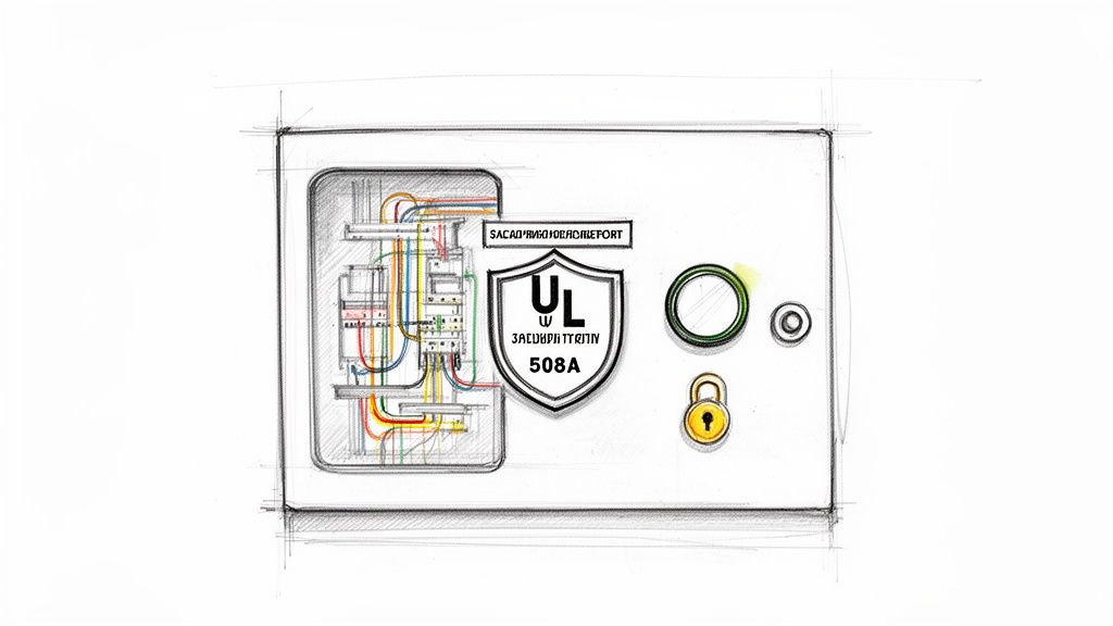
Before you even think about cutting a single wire, we need to talk about why you absolutely must build a control panel to UL standards. This isn't just about getting a sticker for the enclosure door; it’s the entire foundation of safety, reliability, and market acceptance for your machinery. Following a standard like UL 508A is your first and best line of defense against risk.
Why UL Compliance Is Non-Negotiable
When you build a control panel, you're building the brain of a machine or an entire process. If it fails, the consequences can be catastrophic, going way beyond simple downtime. That's where UL 508A, the Standard for Industrial Control Panels, enters the picture. Think of it as a comprehensive blueprint for safety and quality assurance that's recognized and respected all across North America.
This certification isn’t a friendly suggestion—it’s frequently a hard requirement. Many jurisdictions, most insurance carriers, and countless major industrial customers simply won't allow equipment on their floor without that UL mark. For OEMs and packagers, it's a badge of quality that unlocks access to bigger and better markets.
The Foundation of Safety and Reliability
At its core, a UL 508A certification means the panel was designed and built using a proven, systematic methodology. This process validates that every single component is right for the job and that the entire assembly can safely handle its rated electrical load without a problem.
This standardized approach tackles the critical safety details that prevent disasters. We're talking about things like:
Component Spacing: Ensuring proper clearances between parts to stop electrical arcing and manage heat buildup.
Short Circuit Current Rating (SCCR): Verifying the panel can withstand a massive fault current without exploding or catching fire.
Wire Sizing and Protection: Making sure every conductor is sized for its load and backed up by the correctly rated fuse or circuit breaker.
By building to these established rules, you are designing safety into the system from the very beginning, not bolting it on as an afterthought. This ensures the panel not only works on day one but keeps running safely and reliably for years to come.
Understanding the Terminology
It's easy to get lost in the jargon. You'll hear terms like "Listed" and "Recognized" thrown around, and while they sound similar, they mean very different things.
A UL Listed product is a complete, standalone item that has been tested for a specific end-use. A UL Recognized component, on the other hand, is meant to be part of a larger assembly. Knowing the difference is absolutely vital when you're selecting parts. To get the full picture, you can learn more about the crucial differences between UL Listed vs. UL Recognized components in our deep-dive guide.
A non-compliant panel isn’t just a code violation; it’s a tangible risk. It exposes operators to electrical hazards, threatens expensive machinery with catastrophic failure, and can lead to immediate project shutdowns by safety inspectors, costing thousands in lost productivity and rework.
The Real-World Costs of Non-Compliance
Let's be blunt: skipping UL standards is a high-stakes gamble you can't afford to take. Picture a new production line, ready to go, shut down completely because an inspector red-tags an unlisted panel. The cost of that downtime, plus the emergency field rework and potential re-engineering, will instantly eclipse whatever you thought you were saving.
Worse yet, if an electrical fire or accident does happen, the first thing investigators will look at is the equipment's compliance. A non-UL panel creates a massive liability for both the panel builder and the facility owner, and it could be grounds for your insurance company to deny the claim. For any plant engineer or OEM, standardizing on UL 508A panels isn't just good practice—it's a fundamental risk management strategy that protects your people, your equipment, and your company's reputation.
Your Blueprint for a Successful Panel Build
Every great control panel starts long before you pick up a single tool. It begins with a solid plan. Think of your design and documentation as the foundation of your entire project—get it right, and everything else falls into place. This is where you iron out the kinks, prevent costly screw-ups, and make sure the final panel is safe, efficient, and won't be a nightmare to maintain down the road.
Trying to jump straight into a build without a blueprint is like a contractor trying to build a house from a napkin sketch. It's a recipe for disaster. The time you spend planning upfront pays for itself ten times over by cutting down on rework, making parts ordering a breeze, and guaranteeing a smoother assembly.
And the need for well-engineered panels is only growing. The global electric control panel market was valued at a whopping USD 6.37 billion in 2024 and is expected to nearly double to USD 12.15 billion by 2034. This boom is fueled by huge investments in automation and grid modernization, which means the demand for properly documented, compliant panels is higher than ever. If you're interested in the numbers, you can dig into the full electric control panel market research.
Defining the Scope of Work
Before you even think about opening your CAD software, you need a rock-solid Scope of Work (SOW). This document is your North Star. It’s what translates a machine's operational needs into concrete technical specs, ensuring everyone—from the engineer to the wireman to the end-user—is on the exact same page.
A good SOW leaves no room for guessing. It should nail down specifics like:
Motor Loads: List out every single motor. I’m talking horsepower (HP), full-load amps (FLA), voltage, and exactly how it will be controlled (a simple starter, a VFD, a soft starter?).
I/O Points: Map out all your discrete and analog I/O. What kind of sensors are you using (NPN or PNP)? What signal levels do you need (4-20mA, 0-10V)? Any special communication protocols?
Environmental Conditions: Where is this panel going to live? A clean, climate-controlled room is one thing, but a food processing plant that gets washed down daily is another entirely (hello, NEMA 4X). Don't forget to account for potentially hazardous locations.
Power Source: What are you plugging into? Specify the incoming voltage, phase, frequency, and most importantly, the available fault current. You absolutely need this to calculate the panel's Short Circuit Current Rating (SCCR).
Getting these details right in the SOW is non-negotiable. An incomplete scope is the number one cause of mid-project change orders, and those always cost more time and money than you planned for.
Think of your documentation package as the panel’s biography. It tells the story of how it was designed, what it’s made of, and how it’s supposed to work. Without it, future troubleshooting and maintenance become a frustrating guessing game.
Creating Essential Panel Documentation
With a tight SOW, you can now build out the core documents that will guide the hands-on work. These aren't just papers to be filed away; they are the literal instruction manual for building, wiring, and commissioning the panel.
No matter the project size, there are a few foundational documents you'll always need. I've broken them down here to show why each one is so critical to getting the job done right.
Essential Documentation for Your Control Panel Project
Document Type
Purpose and Value
Key Information to Include
Electrical Schematics
This is the complete wiring roadmap. It shows how every single component is electrically connected, making wiring and future troubleshooting possible.
Power distribution, control circuits, I/O wiring, component tags, wire numbers, and terminal block layouts.
Panel Layout Drawing
A physical map of the panel. It shows the precise placement of components on the backpanel and door for an optimal fit and function.
Component dimensions, required clearances for heat dissipation, wire duct routing, and locations for operator devices like buttons and HMIs.
Bill of Materials (BOM)
The comprehensive parts list. This ensures every necessary component is ordered correctly and acts as a checklist during assembly.
Manufacturer part numbers, quantities, descriptions, and component tags that cross-reference back to the schematics.
These documents work together to form a complete picture of your control panel. A tech should be able to pick them up years from now and understand exactly what they're looking at without having to trace a single wire.
From Design to Bill of Materials
Modern CAD software is your best friend here. It’s indispensable for creating accurate schematics and layout drawings that you can trust. Good software helps you visualize component placement and, more importantly, catch common mistakes—like not leaving enough space for wire bending radii or proper airflow for thermal management. A great layout isn't just about cramming everything in; it's about building a panel that’s easy to work on for years.
Once your design is locked in, generating the Bill of Materials (BOM) is the next step. A well-structured BOM is more than just a shopping list. I always recommend organizing it logically by component type (e.g., power distribution, control, I/O). It makes purchasing far less painful and helps the assembly team stage their work efficiently. This detailed planning is what turns a digital design into a real-world, reliable control panel.
Choosing the Right Components for Reliability
The components you pick are the heart and soul of your control panel. Getting this right isn't just about making sure everything fits—it's about building a system that can take a beating day in and day out, all while staying safely within UL specifications. A truly solid panel is built with parts that are correctly sized, properly rated, and tough enough for the environment they'll live in.
It all starts with the core power and control components. Think of them as the engine and transmission of your system. If you get these right, everything else has a strong foundation to build on. This is absolutely not the place to cut corners; the reliability of your entire machine hangs on their performance.
Sizing Your Core Power Components
When you build control panel systems, it's easy to fall into the trap of oversizing "just in case." That's a waste of money. Undersizing? That's just asking for a catastrophic failure. Precision is the name of the game here, and it all begins with understanding your load—which, for most of us, means motors.
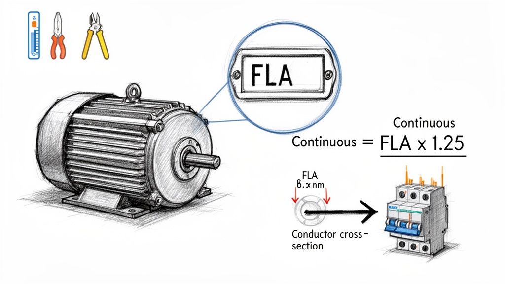
Your calculations have to be based on the motor's Full-Load Amps (FLA), not just its horsepower rating. The FLA is what the motor will actually draw under its intended load, and it's the number that dictates your protective devices.
Circuit Breakers and Fuses: These exist to protect the wire and the motor. A good rule of thumb is to size them at 125% of the motor's FLA for standard motors, but you always need to consult the National Electrical Code (NEC) for the final word, especially when dealing with VFDs.
Contactors and Motor Starters: These switching devices need to be rated for the specific horsepower and voltage of the motor. Don't just match the amperage; you need a contactor that can handle the inductive kick of a motor load.
Variable Frequency Drives (VFDs): Pick your VFD based on the motor's FLA and voltage. And don't forget the duty cycle. A heavy-duty application like a rock crusher demands a much more robust VFD than a simple conveyor belt does.
Sizing everything meticulously ensures each part operates within its safe thermal limits. This simple step prevents those frustrating nuisance trips and keeps components from failing prematurely. You can dive deeper into the specifics of industrial control panel design to really dial in your component selection process.
Selecting the Brains and Nerves
Once your power distribution is mapped out, it's time for the control components. This is your PLC, power supplies, and all the wiring that ties everything together.
The PLC is your central decision-maker. The choice here comes down to the complexity of your process. How many I/O points will you need? What about communication protocols like EtherNet/IP or Modbus TCP? A simple packaging machine might get by with a micro PLC, but a complex robotic cell is going to demand a powerful controller with advanced motion capabilities.
Power supplies are the unsung heroes of any panel. A pro tip: always choose a 24VDC power supply with at least 25-30% more capacity than your calculated control load. That extra headroom accounts for the inrush current when devices first power on and gives you room to add things later without a full redesign.
Choosing components is a balancing act between performance, cost, and availability. But there's one non-negotiable: compliance. Every major component must be UL Recognized to be included in a UL 508A listed panel.
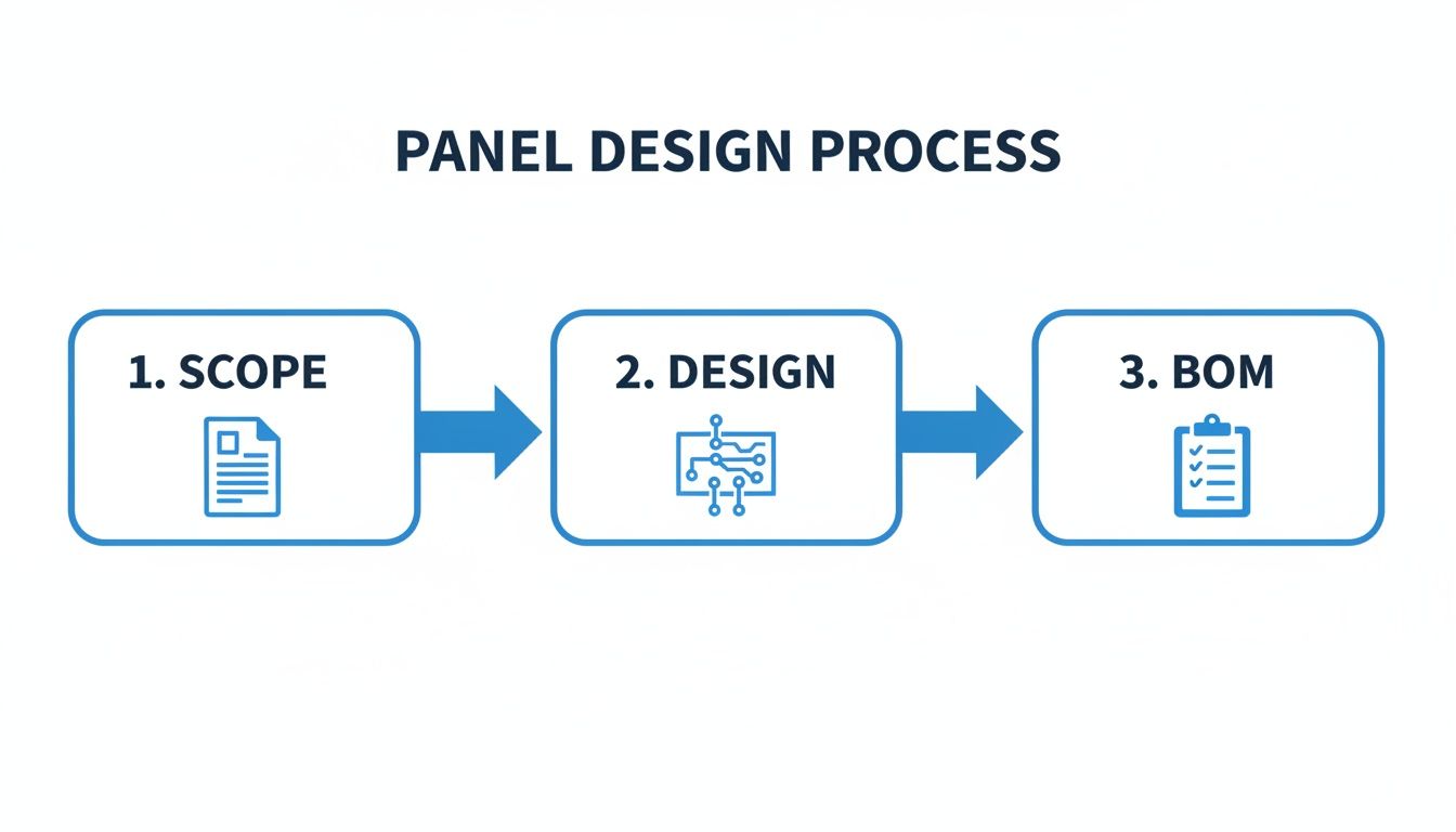
This is where a clear process comes in, moving from the initial project scope to a finalized Bill of Materials. It's the blueprint for everything that follows.
This workflow shows exactly how a detailed design phase prevents procurement mistakes and assembly delays down the road.
Enclosures and Environmental Considerations
The enclosure is your panel's first line of defense. The environment tells you what NEMA rating you need. A NEMA 12 enclosure is perfectly fine for a clean, dry factory floor. But if you’re building a panel for a food processing plant that gets high-pressure washdowns, you need a stainless steel NEMA 4X enclosure to stop corrosion and water from getting in.
Beyond just the components themselves, smart inventory management is a huge factor in project success. Having a clear view of your stock streamlines purchasing and helps you sidestep those last-minute project delays. It's a critical topic covered well in a comprehensive guide to contractor asset and inventory management.
The demand for this work is only growing. The industrial control panels market is set to jump from USD 13.5 billion in 2023 to USD 20.8 billion by 2032. With manufacturing and industrial automation applications grabbing a massive 39.6% of the market in 2024, the pressure to pick high-quality, reliable components has never been higher. This explosive growth shows why getting your component selection right isn't just a best practice—it’s a major competitive advantage.
Bringing the Design to Life: Panel Fabrication and Assembly
This is where the rubber meets the road—where your carefully crafted schematics and digital layouts become a tangible, working piece of hardware. When you build a control panel, you're moving from theory to craftsmanship. A clean, well-organized build isn't just about looking professional; it's the foundation of safety, reliability, and sanity for the maintenance crew who will live with this panel for years.
The real difference between a decent panel and a great one is in the details. It's the small, deliberate choices made during assembly that prevent massive headaches down the line. This is about more than just hooking up wires; it's about building a robust system with precision and foresight.
Nail the Backpanel Layout First
Before you mount a single component, lay everything out on the backpanel. Think of this as a dry run, your last chance to catch physical conflicts before they become a real problem. Place the components according to your drawing and ask the important questions.
Is there really enough breathing room around that VFD for proper cooling? Can I actually get a screwdriver onto the terminal screws of that power supply once the wire duct is in?
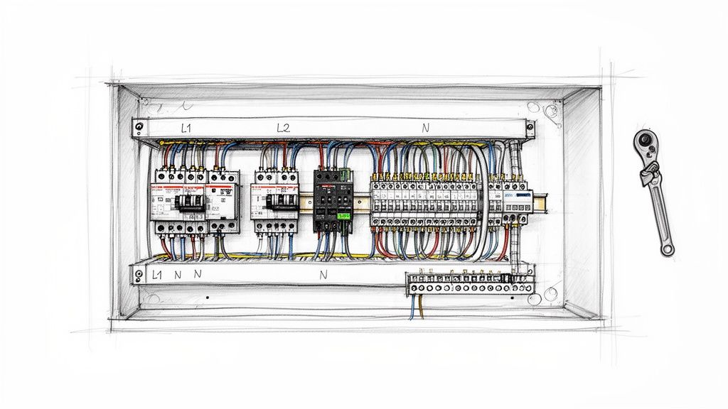
A logical flow is critical. Keep your high-voltage power components—the main disconnect, breakers, and motor contactors—grouped together, typically at the top of the panel. This separates them from the sensitive, low-voltage control electronics like PLCs and I/O cards. This simple act of segregation is your first line of defense against electrical noise, a notoriously frustrating issue to chase down later.
The Craft of Clean Wiring
With components mounted, the wiring begins. The name of the game is methodical neatness. Wire duct is your best friend here, turning a potential rat's nest into clean, organized channels that protect wires and make future inspections a breeze.
A few pro wiring habits will set your work apart:
Label Every Wire, Both Ends: This is non-negotiable. Every wire needs a unique label on each end that matches your schematics. Without this, troubleshooting turns into a painful, time-consuming process of manually tracing circuits.
Get the Wire Length Just Right: Wires cut too short put constant strain on terminal connections, a failure waiting to happen. Wires that are too long create a tangled mess that traps heat and makes it impossible to access components.
Keep Signals Separated: Use different wire ducts or maintain physical distance between your power (480V), control (24VDC), and communication (Ethernet) cables. Running a motor lead right next to a network cable is asking for signal interference.
A well-built panel tells a story of professionalism. When a technician opens the door five years from now, clear labels, neat routing, and solid connections are what turn a four-hour troubleshooting nightmare into a fifteen-minute fix.
Precision Where It Counts: Terminations
The physical connection points are where most panels fail. A loose connection creates resistance, which generates heat, causes intermittent faults, or can even lead to a catastrophic arc flash. This is where meticulous attention to detail pays huge dividends.
First, every stranded wire must get a ferrule. A ferrule is a simple metal sleeve crimped onto the end of a stranded wire, containing all those tiny strands and ensuring a solid, reliable connection in a terminal block. It prevents fraying and guarantees a superior connection over time. A quality crimping tool is essential to get this right.
Just as critical is applying the correct torque to every screw terminal. Component manufacturers provide torque specifications for a reason.
Under-torqued screws create a high-resistance connection, which means heat and a potential fire hazard.
Over-torqued screws can damage the terminal, strip the threads, or crush the conductor, leading to another kind of failure.
A calibrated torque screwdriver isn't a luxury; it's a mandatory tool for building safe, reliable panels. Documenting that terminals have been torqued to spec should be a standard step in your quality control process.
Grounding: The Foundation of Safety and Signal Integrity
Finally, let's talk grounding. A solid grounding system is the backbone of your panel's safety and your secret weapon against electrical noise. Every non-current-carrying conductive part—the backpanel, enclosure door, and component chassis—must be bonded to the central ground bus.
This means more than just running a green wire. Use dedicated grounding terminal blocks and ensure every connection is clean, bare metal-to-metal. On painted enclosures, you need to scrape away the paint where your ground lug connects. This creates a low-impedance path to earth, ensuring circuit breakers and fuses trip instantly in a fault condition. It also provides a stable reference point for your control signals, draining away the electrical noise that causes PLCs and VFDs to act erratically.
Safe Power-Up and Commissioning Protocols
This is it. The moment of truth. After all the design work, component sourcing, and careful assembly, you're ready to flip the switch. This is easily the most critical part of the entire build, and being methodical and safety-obsessed isn't just a good idea—it's mandatory. Rushing now is a sure-fire way to fry expensive components, cause major delays, or worse.
A controlled commissioning process is what separates a smooth handover from a disastrous one. It’s how you turn a static box of wires into a fully functioning, reliable system. Let's walk through the field-tested protocols that will protect your investment and make sure every circuit works exactly as planned.
Pre-Power Safety Verifications
Before you even think about throwing that main disconnect, there’s a series of "dead panel" checks you have to perform. These are non-negotiable. They confirm the integrity of your wiring and catch any immediate faults before they have a chance to let the smoke out.
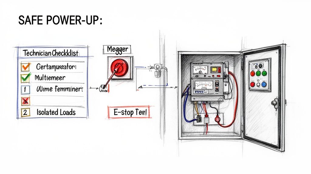
First up is the point-to-point continuity test. Get out your multimeter and your schematics and systematically check every single wire run. It's tedious, but this is how you confirm that Wire 101 actually landed on Terminal 101 and wasn't accidentally swapped with something else. This simple check is your best defense against sending 480V into a sensitive 24V PLC input.
Next, you'll perform an insulation resistance test, what we all call a megger test. By applying a high DC voltage (usually 500V or 1000V), this tool checks for any breakdown in wire insulation. It’ll immediately find pinched wires, damaged insulation, or potential shorts between conductors and the ground. A healthy panel shows incredibly high resistance, telling you everything is properly isolated.
Your pre-power checklist is your final line of defense. Finding a dead short with a multimeter is a minor inconvenience that takes minutes to fix. Finding it with 480V three-phase power is a catastrophic failure that can destroy thousands of dollars in components instantly.
Controlled Initial Power-Up Sequence
Once all the dead-panel checks are complete and signed off, you can move on to a controlled, staged power-up. The key is to energize the panel in sections, verifying each one before moving to the next. All your main loads, like motors, should still be completely disconnected at their terminals.
Main Power Verification: Close the main disconnect and immediately measure the incoming voltage. Make sure it matches the panel's nameplate, and check all phase-to-phase and phase-to-ground voltages. You're looking for stable, correct power.
Control Circuit Energization: Now, power up your control transformer and any 24VDC power supplies. Grab your multimeter again and verify the secondary voltages right at the terminal blocks. You should see a rock-solid 120VAC and 24VDC.
Component Power-On Checks: Do a quick visual scan. All the components with status lights—PLCs, VFDs, network switches—should be powering on. You want to see steady "power on" lights and no red "fault" indicators. This is your basic "smoke test" to ensure nothing was DOA.
Making sure your panel has properly sized protection is a foundational part of this process. This level of electrical infrastructure planning is just as critical as designing robust data center power distribution systems for ensuring uptime. For a more detailed guide on this, check out our article on proper circuit breaker sizing to protect your gear.
Live Functional and I/O Testing
With stable control power and all your core components online, it's time for live functional testing. This is where you bring the logic to life and confirm every single input and output works as designed. It’s a good idea to have the machine operator or a process expert with you for this part.
The game here is to systematically "force" inputs and watch for the correct outputs. For instance, you’ll manually trigger a level sensor and verify that the corresponding pump contactor pulls in.
Your live testing punch list should cover:
Discrete I/O Checks: Go through and trigger every single limit switch, push button, and sensor. Watch for the corresponding input light on the PLC card to illuminate and confirm the logic fires the right output.
Analog I/O Scaling: For your 4-20mA devices like pressure transmitters, use a signal injector or process meter to simulate the signal. Check that the value on the HMI or in the PLC code scales correctly (e.g., 4mA reads 0 PSI, 20mA reads 100 PSI).
Safety Circuit Validation: This is the most important test of all. Physically press every E-stop. Pull every safety pull-cord. Open every interlocked guard door. You must verify that all hazardous motion stops immediately and unconditionally. No exceptions.
Motor Rotation Check: With every other test passed, you can finally "bump" each motor. A quick pulse of power is all you need to confirm its direction of rotation. If it's spinning backward, just shut down, lock out, and swap any two of the three-phase leads.
Running through this complete commissioning process ensures the panel isn't just built to print, but that it’s also safe, reliable, and truly ready for production.
Clearing Up Common Control Panel Questions
When you're deep in a panel build, questions always pop up, especially around compliance and best practices. Getting the right answers from the start is the difference between a smooth project and a series of expensive, time-consuming do-overs.
Let's walk through some of the most common questions we hear from engineers and technicians out in the field. Think of this as the practical knowledge you need to connect the dots between your schematics and a rock-solid, compliant panel.
What’s the Real Difference Between UL Listed and UL Recognized?
This is probably the single most important distinction to get right.
A UL Listed mark is for a complete, standalone product that's been tested for a specific purpose. Your main circuit breaker? That’s a perfect example of something that should be UL Listed. It’s a self-contained device ready for its intended job.
A UL Recognized component, however, is a part that's meant to be used inside a larger UL Listed assembly. To build a UL 508A Listed panel, you have to use these UL Recognized components according to a certified shop's specific procedures. You can't just put a UL Listed VFD into a box and call the whole thing "UL Listed." The entire, completed panel has to be certified as a system.
How Do I Figure Out the Right Enclosure Size?
Sizing an enclosure is about much more than just making sure the components physically fit. One of the classic mistakes is packing everything in too tightly, which is a recipe for overheating and early component death.
You've got to think about the details that aren't on the component's spec sheet:
Wire Bend Radius: Big wires don't like to make tight turns. You have to leave plenty of room to bend them without damaging the conductor or violating code.
Heat Dissipation: VFDs, power supplies, and transformers throw off a lot of heat. Without enough space for air to move, you're essentially slow-cooking your electronics.
Room to Grow: Always plan for the future. A smart rule of thumb is to keep 25-30% of your backpanel space free for future additions or modifications.
That "empty" space isn't wasted—it's a smart investment in the panel's reliability and makes life easier for anyone who has to service it down the road. And don't guess on cooling; always do the thermal calculations to see if you need fans or an AC unit.
The most common mistakes in a panel build often come down to the small details: improper grounding creating electrical noise, inconsistent wire labels making troubleshooting impossible, and failing to torque terminal connections to spec, which can lead to arcing and catastrophic failure.
What Are the Most Common Panel Building Mistakes?
Besides getting the enclosure size wrong, a few other common slip-ups can really compromise a panel's safety and function.
The number one problem we see? Inconsistent or missing wire labels. It seems small, but it turns a five-minute troubleshooting job into an all-day nightmare of manually tracing circuits.
Another big one is improper grounding. Get this wrong, and you can introduce electrical noise that causes PLCs and other sensitive gear to act erratically. And finally, failing to manage heat with proper ventilation is a direct path to components failing way sooner than they should.
Getting the circuit breaker size right is one of those fundamental tasks that separates a reliable, safe industrial system from a problematic one. It’s a careful balancing act: the breaker's amp rating needs to be high enough to handle the normal operational current but low enough to trip before the wires overheat and create a fire hazard.
For anyone working on industrial gear—OEMs, packagers, plant engineers—this isn't just about theory. Critical details like motor inrush current and high ambient temperatures can make or break a design.
Why You Can't Afford to Get Breaker Sizing Wrong
Meticulous circuit breaker sizing is far more than a simple box-checking exercise; it’s the bedrock of a dependable system. A miscalculation here creates a cascade of problems that can haunt you long after commissioning. This is about building machines and control panels that just work, day in and day out.
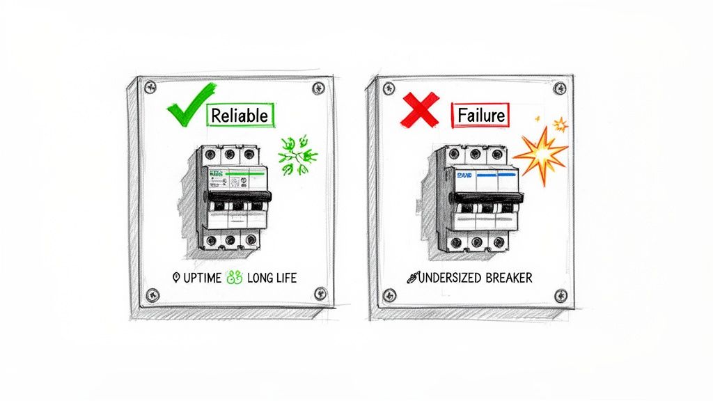
An undersized breaker is a constant headache. It leads to nuisance trips that kill production and send operators scrambling. On the other hand, an oversized breaker is a genuine menace. It won't protect the conductor from overheating, which is a textbook fire risk that can destroy expensive equipment and, worse, endanger your team.
The Real-World Impact on Operations
Precision here directly translates to uptime, the lifespan of your equipment, and even the profitability of a project. The demand for correctly specified components is massive. The global circuit breaker market hit USD 23.2 billion in 2024, with growth being pushed by the need for smarter, safer electrical systems.
At the end of the day, a circuit breaker’s number one job is to protect the wire. Every decision you make has to flow from that single principle. If the breaker doesn’t open the circuit before the conductor’s temperature limit is breached, it has failed.
Before we dive into the nitty-gritty calculations, it's helpful to have a high-level view of the key considerations. This table summarizes the core pillars we'll be covering, acting as a quick reference guide.
Key Factors in Circuit Breaker Sizing
Sizing Factor
Primary Consideration
Relevant Code/Standard
Load Assessment
Differentiating continuous vs. non-continuous loads; calculating total amps.
NEC Article 220
Code Compliance
Applying the 125% rule for continuous loads and motor-specific FLC rules.
NEC Article 210, 430
Conductor Ampacity
Ensuring the wire gauge can safely handle the current under its conditions of use.
NEC Table 310.16
Environmental Factors
Applying derating for high ambient temperatures or multiple conductors in a conduit.
NEC Article 310.15
Interrupting Rating
Confirming the breaker can safely interrupt the maximum available fault current.
NEC Article 110.9
Selective Coordination
Ensuring the correct breaker trips to minimize the scope of an outage.
NEC Article 700.32
Each of these factors is a critical piece of the puzzle. Let's start breaking them down one by one.
Laying the Groundwork: Your Load and Conductor Foundation
Before you even think about grabbing a circuit breaker off the shelf, you have to answer a simple question: what, exactly, are you protecting? Every circuit breaker sizing job starts here, with a deep dive into the load. This isn't just about adding up amps; it's about really understanding what your equipment needs to operate safely and reliably.
This first step is what dictates your conductor size, and the two are joined at the hip. A breaker’s number one job is to protect the wire from melting down. If you don't have an accurate load profile, you're just guessing. That leads to two bad outcomes: constant nuisance tripping that kills productivity, or a catastrophic fire hazard because your breaker is too big for the wire.
Continuous vs. Non-Continuous Loads: Why It Matters
The first thing to sort out is the nature of your loads. The National Electrical Code (NEC) doesn't treat all electrical loads the same because they don't all generate the same amount of heat.
Non-Continuous Load: Think of this as something that runs for less than three hours at a time. A small conveyor motor that cycles on and off or a temporary work light are perfect examples.
Continuous Load: This is the big one in most industrial plants. A load is considered continuous if it's expected to run at its maximum current for three hours or more. We're talking about your big HVAC systems, workhorse air compressors, and pumps that run an entire shift without a break.
This isn't just a technicality—it fundamentally changes your math. The NEC requires you to build in a safety factor for any continuous load to handle the extra heat.
Applying the 125 Percent Rule
To deal with the thermal stress from equipment that runs for hours on end, NEC Article 210.19(A)(1) is crystal clear. It states that your branch circuit wires must have an ampacity of no less than 125% of the continuous load. By extension, the circuit breaker protecting that wire gets sized using the same logic.
Think of it as a built-in safety cushion. This 125% multiplier makes sure your wires and breakers aren't screaming hot at their absolute thermal limit all day long. It's one of the most common corners people cut, and it's a recipe for circuits that run way too hot and breakers that pop for no apparent reason.
Here's a quick example. Say you have a heater bank that pulls a steady 20 amps and runs all day.
You have to size your wire and breaker for at least: 20A x 1.25 = 25A
That means you're reaching for a 25A circuit breaker and picking a wire that can handle at least 25A (after you've accounted for any other derating factors, which we'll get to).
Finding Your Full Load Amps (FLA)
To do any of this math, you need real numbers. The absolute best place to get current data for any piece of equipment is its nameplate. That little metal tag is packed with gold, including the Full Load Amps (FLA)—the current a motor draws when it's doing the work it was designed for.
If the nameplate is missing or unreadable, your next best bet is the manufacturer's spec sheet or the engineering submittals. For standard three-phase motors, you can also turn to the tables in NEC Article 430 (specifically Tables 430.248, 430.249, and 430.250) to get a Full Load Current (FLC) based on horsepower and voltage. But if you have the nameplate, use it. It reflects how that specific motor actually performed in testing.
Here's a pro tip that trips up a lot of people: Always use the motor nameplate FLA for sizing your conductors and overload protection. But for sizing the breaker (the short-circuit and ground-fault protection), you have to use the NEC tables. It’s a specific nuance in NEC Article 430 that's easy to miss.
Let's walk through a real-world scenario with a small control panel.
Example: A Mixed-Load Control Panel
Imagine you're engineering a panel on a 480V/3-phase system with this equipment:
Motor 1: A 10 HP pump motor (runs all day—continuous)
Motor 2: A 3 HP conveyor motor (cycles on and off—non-continuous)
Heater: A 5 kW resistive heater strip (on for hours—continuous)
First, we hunt down the FLA for each load:
Motor 1 (10 HP): Nameplate says 14A.
Motor 2 (3 HP): Nameplate says 4.8A.
Heater (5 kW): We need to do a quick calculation: (5000 W) / (480V * √3) = 6.0A.
Now we can apply the 125% rule where it's needed—only on the continuous loads.
By sorting our loads and doing the math correctly, we now have the real-world amperage values we need. This solid foundation is what allows us to move on to the next step: sizing our conductors properly before we pick out the final breakers.
Once you have your load calculations nailed down, it's time to get into the nitty-gritty of the National Electrical Code (NEC). This isn't just a box-ticking exercise; it’s about applying the rules correctly to build a system that's both bulletproof and reliable. Think of the NEC as the official playbook that helps us sidestep catastrophic failures and annoying nuisance trips.
You'll be spending most of your time in two key areas: NEC Article 240, which lays out the fundamentals of Overcurrent Protection, and NEC Article 430, the bible for everything related to Motors and Motor Circuits. These articles give you the roadmap to go from a calculated load to a compliant, real-world breaker.
Getting this right is a huge deal. The circuit breaker market is projected to explode from USD 25.2 billion in 2025 to an incredible USD 57.5 billion by 2035. That growth is all about the increasing need for precisely sized, reliable protective devices. For a common 50HP motor running at 460V, a simple sizing mistake can lead to much higher failure rates, turning a small oversight into a major headache.
Sizing for Motor Branch Circuits
Motors are a special breed. When they kick on, they draw a massive surge of current for a few seconds—what we call inrush current. This spike can hit anywhere from 600% to 800% of their normal running current, or Full Load Amps (FLA). If you sized a breaker just for the FLA, it would see that inrush as a dead short and trip every single time.
This is where NEC Article 430.52 comes in. It gives us permission to use specific multipliers to size a motor’s branch circuit protection (like a thermal-magnetic breaker) well above the motor's FLA.
For a typical thermal-magnetic breaker, the NEC allows you to size it up to 250% of the motor's Full Load Current (FLC) from the NEC tables. This buffer is there specifically to allow the motor to get up to speed without tripping the breaker, while still giving you solid protection against a true short circuit.
A lot of people see that 250% number and treat it like a target. It's not. It’s a maximum ceiling. Your goal should be to pick a breaker that's just big enough to handle the inrush, but as close as possible to the motor's needs to provide tighter, more effective protection.
The Critical Step: Derating for the Real World
Now we get to one of the most important—and most frequently missed—parts of sizing: derating. A wire's ability to carry current, its ampacity, isn't set in stone. It drops when things get hot or when wires are bundled together in a raceway.
These real-world conditions create heat that the wires can't shed easily. The NEC gives us correction factor tables to adjust, or derate, the wire's ampacity to account for this. And since the breaker’s entire job is to protect that wire, any reduction in the wire’s ampacity directly affects your breaker choice. You have to size the breaker to protect the wire at its final, derated value.
Dealing with High Ambient Temperatures
The ampacity values you see in NEC Table 310.16 are all based on a cozy 86°F (30°C). But if your panel is sitting in a boiler room, on a sun-baked rooftop, or anywhere the temperature regularly climbs higher, you have to apply a correction factor.
Let's say you're running 90°C-rated THHN wire in a spot that regularly hits 104°F (40°C). According to the NEC, you have to multiply its base ampacity by 0.91. Suddenly, a wire that was good for 100 amps is now only rated for 91 amps, and your breaker size has to come down to match.
Adjusting for Bundled Conductors
Heat also becomes a problem when you pack multiple current-carrying conductors into the same conduit. NEC Table 310.15(C)(1) gives us the adjustment factors for this exact scenario.
1-3 Conductors: You're in the clear, no adjustment needed.
4-6 Conductors: Reduce the ampacity to 80% of its value.
7-9 Conductors: Reduce it down to 70%.
The more wires you cram in there, the more you have to derate. This is also where things can get complex, as these adjustments can interact with other rules, which is something we cover in our guide on the NEC tap rule.
To illustrate, here are some common situations where derating is essential.
Common Derating Scenarios and Adjustments
Scenario
Applicable NEC Table
Example Ampacity Adjustment
Impact on Sizing
Conductors in a hot attic (125°F / 52°C)
Table 310.16
For 90°C wire, apply a 0.76 correction factor.
A 50A wire becomes a 38A wire, requiring a smaller breaker.
5 current-carrying conductors in a conduit
Table 310.15(C)(1)
Adjust ampacity to 80% of its listed value.
A 30A circuit may now require a larger wire gauge to be protected by a 30A breaker.
8 conductors in a conduit in a hot attic
Both Tables
The two factors are multiplied together (e.g., 0.76 x 0.70).
The wire's capacity is drastically reduced, demanding a much smaller breaker.
Solar conduits on a commercial rooftop
Table 310.16
Ambient temperature adders may apply on top of the base temp.
This often results in significant ampacity reduction and upsizing of conductors.
These examples show that you can't just look at the base ampacity of a wire; you have to consider the environment to select the right breaker.
A Quick Derating Example
Let's put it all together. Imagine you're pulling nine current-carrying 90°C THHN conductors through one conduit in a factory space where the ambient temperature is a toasty 110°F (43°C).
Temperature Correction: From NEC Table 310.16, the factor for 43°C is 0.87.
Conductor Adjustment: For nine conductors, Table 310.15(C)(1) tells us to use a factor of 0.70 (70%).
Now, just multiply these together. If we're using 10 AWG THHN wire with a base ampacity of 40A (from the 90°C column), the math looks like this:
Even though we started with a 40A wire, under these specific conditions, its true safe capacity is only 24.36 amps. That means the largest breaker you can put on this circuit is a 20A or 25A model (depending on standard sizes). This is a perfect example of why derating isn't just a suggestion—it's the final word in getting breaker sizing right.
Mastering Short-Circuit Ratings and Coordination
Sizing a circuit breaker for predictable overloads is just the start. If you want to build a truly resilient and safe industrial system, you have to plan for the immense, destructive energy of a short circuit. This is where we move past just protecting a single wire and start thinking about system-level reliability under the absolute worst conditions.
It's easy to confuse a standard overload with a short circuit, but they're worlds apart. An overload is a slow burn—a motor struggling, a circuit drawing a bit too much current, generating heat over time. A short circuit is a violent, nearly instant surge of thousands of amps that can vaporize metal and cause catastrophic failure. Your breaker's standard trip settings are far too slow for this; you need a device that can physically withstand and extinguish that explosive arc.
Understanding Interrupting Ratings
This brings us to the Interrupting Rating, or Ampere Interrupting Capacity (AIC). The AIC is the absolute maximum short-circuit current a breaker can safely interrupt without blowing itself to pieces.
There’s one non-negotiable rule here: the breaker’s AIC rating must be higher than the available fault current (AFC) at its installation point. If the AFC at a panel is 12,000 amps and you install a breaker rated for only 10,000A (10kA), it will fail violently during a major fault. We're talking arc flash explosion potential.
Figuring out the AFC usually requires a short-circuit study, which looks at the utility transformer size, conductor lengths, and impedance. While you can often use standard values for smaller systems, a formal calculation is a must for large industrial facilities. Safety depends on it.
The Power of Selective Coordination
Once you've confirmed your breakers can survive a fault, the next step is to control how they respond. This is the whole idea behind selective coordination—a design strategy that stops a small, localized fault from triggering a widespread outage. It's the difference between a minor hiccup and a full-blown production shutdown.
The goal is simple: only the circuit breaker immediately upstream of the fault should trip. All the breakers further up the chain need to stay closed, keeping power flowing to everything else.
Think about a large control panel with a main 400A breaker feeding dozens of smaller 20A branch circuits. If a fault happens on a single 20A motor circuit, a coordinated system ensures only that 20A breaker opens. Without coordination, that same small fault could trip the 400A main, needlessly killing power to every single load in the panel.
Selective coordination is a cornerstone of reliable power system design, especially in critical facilities like hospitals and data centers where uptime is paramount. For industrial plants, it's a powerful tool to minimize costly downtime and simplify troubleshooting.
How to Achieve Coordination
Getting coordination right means digging into the time-current curves (TCCs) of your upstream and downstream breakers. These graphs show exactly how long a breaker takes to trip at any given current. For coordination to work, the entire curve of the downstream breaker has to sit below the curve of the upstream breaker, with zero overlap. This guarantees the device closest to the fault always has time to act first.
Major manufacturers provide software and tables to make this much easier. When you're designing with specific product lines, you can often just consult their published coordination tables, which show which breaker combinations are proven to work together. If you're looking for guidance on specific components, our overview of the ABB circuit breaker lineup can be a helpful starting point.
The push for these advanced protection schemes is only getting stronger. The market, valued at USD 22.13 billion in 2025, is on track to nearly double to USD 44.81 billion by 2035, driven by a 7.31% CAGR from growing electrification in manufacturing. Medium-voltage breakers, which often require careful coordination, already hold a 45% market share. Having built custom UL panels since 1974, we see this trend firsthand in the demand for smarter, better-engineered motor control centers. You can find more details in the full circuit breaker market analysis from Precedence Research.
By mastering both interrupting ratings and selective coordination, you elevate your work from basic circuit protection to thoughtful system design. This approach ensures your systems are not just safe from a short circuit’s raw power, but also smart enough to contain disruptions and keep your operations humming.
A Complete Sizing Walkthrough for a UL 508A Panel
Theory is great, but putting it into practice is where the rubber really meets the road. Let’s walk through a complete, numbers-driven sizing example for a pretty common UL 508A industrial control panel.
This scenario will tie together everything we've talked about—load calcs, derating, and the critical NEC rules—into a workflow you can actually use on your own projects.
Imagine you're engineering a control panel for a small conveyor system. The power feed is 480V/3-Phase, and the panel will live indoors where the ambient temperature can hit 104°F (40°C).
Establishing the Panel Loads
First thing's first: we have to identify every single load inside this panel. For this project, our list is straightforward:
Motor 1 (M1): A 15 HP main drive motor, running continuously.
Motor 2 (M2): A 5 HP auxiliary motor, also a continuous load.
VFD: A variable frequency drive for that 15 HP motor.
Control Transformer: A 500 VA (0.5 kVA) transformer to create our 120V control power. This is a continuous load.
Calculating Branch Circuit Requirements
Okay, now we size the protection for each individual branch circuit. We'll start with the motors, using FLC values from NEC Table 430.250 for the breakers. Just remember, conductor sizing is based on FLA (though for this exercise, we'll assume FLA and FLC are the same).
Motor 1 (15 HP drive motor)
NEC Table 430.250 tells us the FLC for a 15 HP motor at 480V is 21A.
For the wire, we need that 125% multiplier for continuous duty: 21A x 1.25 = 26.25A. This means we need a conductor with at least that ampacity. We'll go with 10 AWG THHN copper wire, which is good for 35A at 75°C.
For the breaker, we need to account for inrush current. NEC Table 430.52 gives us a 250% multiplier: 21A x 2.50 = 52.5A. You can't just grab a 52.5A breaker off the shelf. Per NEC 240.6, you have to round down to the next standard size. That lands us at a 50A thermal-magnetic breaker.
Motor 2 (5 HP auxiliary motor)
The FLC for a 5 HP motor is a much smaller 7.6A.
Conductor sizing is next: 7.6A x 1.25 = 9.5A. 14 AWG THHN wire is rated for 20A at 75°C, so that's plenty.
Breaker sizing: 7.6A x 2.50 = 19A. Here, the "next size up" rule applies, so we can safely select a standard 20A breaker.
Control Transformer (500 VA)
First, we need the primary current: 500 VA / 480V = 1.04A.
Sizing the breaker is governed by NEC 450.3(B), which lets us size primary-only protection up to 125% of the primary current: 1.04A x 1.25 = 1.3A. A standard 2A supplementary protector is the perfect fit for this control circuit.
Sizing the Main Feeder and Breaker
With all the branches handled, it's time to size the main incoming breaker for the whole panel.
NEC 430.24 gives us the formula: 125% of the largest motor's FLC + the sum of all other motors' FLC + the sum of all other loads.
Let's do the math:
Largest Motor Calc:21A (15 HP motor) x 1.25 = 26.25A
Add Other Motors:26.25A + 7.6A (5 HP motor) = 33.85A
Add Other Loads:33.85A + 1.04A (transformer) = 34.89A
Our calculated total load comes out to 34.89A. The next standard breaker size up from that value is 40A. So, we'll spec a 40A main circuit breaker.
Applying Derating Factors
We're not quite done. The final—and crucial—step is to double-check that our conductors can handle the load under the panel's actual operating conditions.
Remember that 40°C ambient temperature? Using NEC Table 310.15(B)(1), the correction factor for our 75°C wire is 0.88. Let's check the 10 AWG wire we picked for the 15 HP motor:
Derated Ampacity = 35A (base ampacity) x 0.88 = 30.8A
Our required ampacity was 26.25A. Since 30.8A is greater than that, our 10 AWG wire is good to go. This kind of systematic process is the absolute cornerstone of safe and effective industrial control panel design.
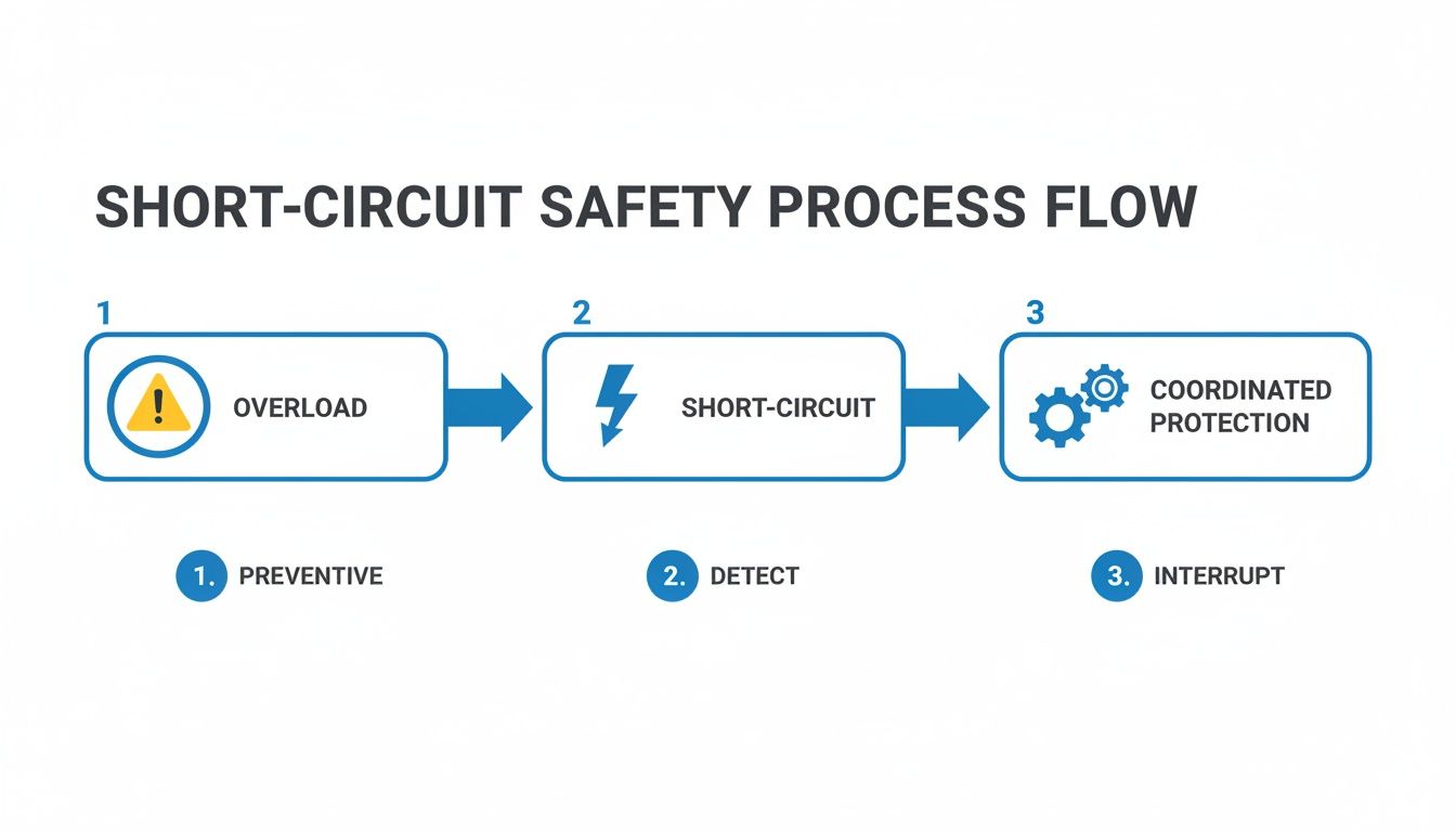
This flowchart really brings the safety process into focus, from preventing simple overloads to coordinating protection for a major short circuit.
It’s a great visual reminder that robust protection is about more than just tripping on an overload. It’s a full strategy for interrupting faults safely and selectively.
The Final Sanity Check: Always, always verify your work. Does each branch breaker actually protect its conductor? Does the main breaker protect the main feeders? Are all the interrupting ratings high enough for the available fault current? This last review is what prevents expensive mistakes and ensures you're building something that's safe and built to last.
Even after you get a solid process down for sizing breakers, some questions just keep coming up. I see them all the time in the field—these are the real-world gray areas that can trip up even experienced engineers and lead to code violations or, worse, unsafe equipment.
Let's clear the air on a few of the most common ones.
Can I Just Use the Next Standard Breaker Size Up?
It’s tempting, I get it. But grabbing the next size up is almost always the wrong move.
That "next size up" rule you might have heard about, found in NEC 240.4(B), is incredibly specific and loaded with restrictions. A big one is that it generally doesn't apply to motor circuits (they have their own rules in Article 430) or any circuit over 800A.
Slapping an oversized breaker on a standard circuit is a serious fire hazard. The breaker's number one job is to protect the wire from melting down. If you round up when you shouldn't, you create a dangerous gap where the conductor can get dangerously hot long before the breaker ever thinks about tripping.
Always size the breaker to protect the wire at its final, derated ampacity. No exceptions.
What's the Difference Between UL 489 and UL 1077 Breakers?
This one is absolutely critical for anyone building industrial control panels. The two are not interchangeable.
A UL 489 Miniature Circuit Breaker (MCB) is a listed device specifically designed for branch circuit protection. Think of it as the primary, frontline defense for a circuit.
On the other hand, a UL 1077 device is just a "supplementary protector." It's only meant for use inside listed equipment, providing an extra layer of protection for sensitive components like a PLC's power supply. It simply doesn't have the muscle (the interrupting rating) to handle a true branch-level fault.
Using a UL 1077 device where a UL 489 breaker is required is a common and dangerous code violation. It creates a massive safety risk because the device was never tested or built to handle the kind of fault currents it could see at the head of a circuit.
How Should I Size a Breaker for a Variable Frequency Drive?
When you’re working with a Variable Frequency Drive (VFD), there is only one source of truth: the manufacturer's installation manual. The power electronics inside a modern VFD are incredibly sophisticated and require very specific protection.
VFD manufacturers do extensive, destructive testing to figure out the exact breaker size and type (like thermal-magnetic vs. instantaneous trip) needed to protect the drive from short-circuit damage without nuisance tripping. Just sizing the breaker based on the motor's Full Load Amps (FLA) is a recipe for failure and will likely void the drive’s warranty.
Bottom line: Always follow the VFD manufacturer's tested and approved recommendations.
For over 50 years, E & I Sales has been the partner that engineers, OEMs, and plant managers trust for reliable motor control and power distribution solutions. If you need help specifying the right components or designing a complete UL-listed control panel, our team has the expertise to deliver a safe, compliant, and robust system. Visit us at https://eandisales.com to learn more.
Before you even think about pulling wire, it’s critical to understand what a shunt trip breaker really is. This isn't your standard overcurrent device; it's an intelligent safety switch. Its entire purpose is to give you the power of remote, instantaneous disconnection when an external signal—like an E-stop or fire alarm—tells it to act. This single feature elevates a simple electrical panel from a passive box to an active player in your facility's safety system.
Understanding the Role of a Shunt Trip Breaker
A normal circuit breaker only cares about one thing: electrical problems like overloads and short circuits. That's essential, of course, but it leaves a massive safety gap. A standard breaker has zero awareness of a fire breaking out, a gas leak, or a critical machine going haywire. This is exactly where the shunt trip breaker comes in.
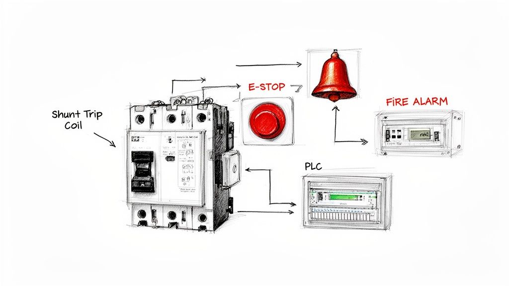
It works by adding an electromagnetic coil (the "shunt coil") to the breaker's internal mechanism. This coil allows the breaker to be tripped by a separate, low-power control signal. In simple terms, you're giving your electrical system ears. Now, it can listen for commands from other safety systems scattered throughout your building.
Real-World Applications and Why They Matter
The real value of a shunt trip breaker clicks into place when you look at scenarios where cutting power right now is absolutely non-negotiable. Without it, energized equipment can become a deadly hazard for first responders or make a bad situation infinitely worse.
You’ll see them in all sorts of industrial and commercial settings:
Emergency Stop (E-Stop) Circuits: Think about manufacturing lines, CNC machines, or conveyor systems. An operator hits a big red button, and a signal instantly fires to the shunt trip, killing power to the machinery and preventing a serious injury.
Fire Alarm Integration: When a smoke or heat detector goes off, the fire alarm panel can trigger the shunt trip to de-energize an entire electrical room or specific high-risk equipment. This is a huge step in preventing an electrical fire from spreading.
Automated System Faults: A Programmable Logic Controller (PLC) monitoring a critical process can be programmed to trip the main breaker via its shunt coil if it detects a dangerous condition, like a tank over-pressurizing or a motor overheating.
Here's the key takeaway: a shunt trip breaker doesn't replace standard overcurrent protection—it adds a second, totally independent way to trip. You get both automatic fault protection and remote emergency control, all packed into a single device.
Integrating shunt trip breakers is often a core part of a facility's overall fire safety strategy. For a deeper dive on this, check out these guides on warehouse fire safety protocols. This kind of integration is becoming less of a "nice-to-have" and more of a requirement for compliance and keeping people safe. If you're looking for specifics on components, you might want to look at our guide on the ABB circuit breaker series and all the accessories available. https://eandisales.com/uncategorized/abb-circuit-breaker/
The demand for these devices tells the story. The global market for shunt trips has already hit around USD 1.1 to 1.2 billion, which shows just how critical they've become in modern electrical design. As more facilities move toward automated safety systems, that number is only going to climb. Getting a handle on these applications is the first, most important step before you start the hands-on work of wiring one up.
Getting Your Gear and Safety Straight
Before a single wire gets connected, let's talk about prep work. Getting organized now, with the right parts and a safety-first mindset, is what separates a smooth installation from a costly, frustrating one. Think of this as the pre-flight checklist for your shunt trip breaker install.
Nailing this stage means you avoid that dreaded pop when mismatched voltage instantly fries a brand-new coil. More importantly, it ensures you walk away from the job safely, which is always priority number one.
The Essential Parts List
At its core, this setup is all about a few key pieces working together in perfect harmony. I can't tell you how many service calls I've been on where the root cause was simply mismatched components. Double-check every single spec before you start.
Here's your shopping list:
The Shunt Trip Breaker: This is the star of the show. Make sure it has the right amperage rating for your load circuit. Critically, its shunt coil voltage must match your control circuit voltage.
A Control Voltage Source: This is the power that actually trips the breaker. It's totally separate from the high-voltage power flowing through the breaker. You'll typically use a 24V DC power supply or a 120V AC control transformer.
An Actuating Device: This is your trigger. It could be a big red mushroom-head Emergency Stop (E-Stop) button, a dry contact from a fire alarm panel, or even an output from a PLC.
Control Wiring: Grab some properly sized and color-coded wire. For most control circuits, 18 AWG or 16 AWG wire is plenty, but always check your local codes, especially if you have a long wire run.
A Tip From the Field: The number one mistake, hands down, is smoking the shunt coil with the wrong voltage. A 24V DC coil will vaporize instantly if you hit it with 120V AC. Always, always read the fine print on the breaker or the accessory module to confirm the coil voltage, and then match your control power source to it precisely.
Your Non-Negotiable Safety Checklist
Let's be clear: working inside a live electrical panel is dangerous business, even for seasoned pros. Complacency is the real enemy here. Before your hands go anywhere near a terminal, you absolutely must establish a safe work condition. This isn't just a suggestion; it's a life-saving discipline.
Lockout/Tagout (LOTO) Is Not Optional
This is always your first move. Never, ever assume a panel is dead just because a switch is in the "off" position.
Find the Source: First, identify the main breaker or disconnect that feeds the panel you're about to open up.
Lock It Out: Flip that breaker to the "Off" position and slap your personal lock and tag on it. Your tag needs to say who you are and why that circuit is locked out.
Prove It's Dead: This is the step people tragically skip. Get out a multimeter you trust and test for voltage. Check everything: phase-to-phase, phase-to-neutral, and phase-to-ground. You need to be 100% certain there is zero energy. A good habit is to test your meter on a known live source first (like a wall outlet) to make sure it's working before you trust it with your life.
Suit Up with the Right PPE
Your Personal Protective Equipment (PPE) is your last line of defense if something goes wrong. The exact level of PPE you need depends on the arc flash hazard rating of the equipment, but for most control panel work, this is a solid baseline.
Safety Glasses: A no-brainer. Protect your eyes from flying debris or the intense light of an arc flash.
Insulated Gloves:Class 0 gloves, rated for up to 1000V, are the standard for this kind of work. Give them a quick inspection for pinholes or tears before every single use.
Flame-Resistant (FR) Clothing: A long-sleeve FR shirt and pants provide that crucial barrier against the intense heat of an electrical incident.
Alright, with your parts verified and your safety protocols locked in, you've laid the groundwork for a clean, professional job. Now you’re ready to start pulling wires.
Alright, with your components in hand and safety procedures locked in, it's time to wire this thing up. Connecting a shunt trip breaker isn't rocket science, but it absolutely demands precision. One wrong wire, and you could have a coil that fails to fire in an emergency or, just as bad, a coil that fries itself the second you power up the control circuit.
The core idea is simple: you're building a separate, low-power circuit that has one job—to tell the main breaker when it's time to trip. This control circuit is completely isolated from the heavy-duty power flowing through the breaker's main terminals. Getting this part right is everything.
This whole process really starts before you even touch a wire. As the flow shows, having the right gear, tools, and verified components is the foundation for a successful and safe installation.
Locating Your Connection Points
First things first, you need to find where to land your wires. On most modern breakers, the shunt trip accessory is a small module that either ships pre-installed from the factory or simply snaps onto the side of the breaker. It will have two dedicated screw terminals, often labeled S1 and S2, or sometimes just marked with the coil's rated voltage (like "24VDC" or "120VAC").
These two little screws are your targets. It's critical not to confuse them with terminals for other accessories, like an auxiliary contact or an undervoltage release. When in doubt, always pull up the manufacturer's datasheet—it's the only way to be 100% sure you've found the right spot.
Wiring for a Single E-Stop Button
Let's walk through the most common setup out there: connecting a shunt trip breaker to a single, normally open (NO) Emergency Stop button. This is your classic "energize-to-trip" circuit.
Power to the Switch: Run a wire from the positive (+) terminal of your control power source (a 24V DC power supply is a common choice) over to one side of the E-stop button's normally open contact block.
Switch to the Breaker: From the other side of that E-stop contact, run another wire to one of the shunt trip terminals on the breaker (we'll call it S1).
Complete the Loop: Finally, run a wire from the second shunt trip terminal (S2) all the way back to the negative (-) or common terminal of your control power supply.
That’s it. In its normal state, the circuit is open, and the coil sees no power. But the moment someone slaps that big red button, the contact closes, the circuit is completed, and voltage zips over to the shunt coil, tripping the breaker instantly.
Handling Multiple E-Stops in Series
On larger machinery, you’ll often find several E-stop buttons located at different operator stations. You need any one of them to kill the power. The way to do this is by wiring the E-stop buttons in series.
Start by running power from your source to the input of the first E-stop.
Then, you simply "daisy-chain" from the output of the first button to the input of the second, and so on down the line.
The output of the very last E-stop in the chain is what finally connects to the shunt trip coil.
With this configuration, pressing any button in the series breaks the chain, completing the circuit to the coil and tripping the breaker. It's a standard, bulletproof safety design.
Expert Insight: It’s easy to forget just how critical these components are. The total market for circuit breakers was valued at USD 22.70 billion and is projected to hit USD 30.32 billion by 2030. The low-voltage segment, where shunt trips are most prevalent, makes up a staggering 66.7% of that market. This just goes to show how fundamental these safety devices are in almost every modern electrical system. You can get more details from these circuit breaker market trends and forecasts.
The wiring for shunt trip circuits can vary based on what's triggering the trip. Below is a quick-reference table showing some of the most common control scenarios you'll encounter in the field.
Wiring Diagrams for Common Shunt Trip Scenarios
Control Scenario
Actuating Device
Key Wiring Consideration
Diagram Reference
Emergency Stop
Normally Open (NO) E-Stop Pushbutton
Circuit is completed when the button is pressed, energizing the coil.
Classic "energize-to-trip" schematic.
PLC Control
PLC Relay Output
PLC logic determines when to close the relay, sending power to the shunt coil.
Connect PLC output as you would a simple switch.
Fire Alarm System
Fire Alarm Control Panel (FACP) Relay
The FACP relay closes on alarm, tripping the breaker to shut down equipment like HVAC units.
Wire in series with the FACP's dedicated normally open relay contacts.
Process Monitoring
Pressure or Temperature Switch
A normally open switch closes when a process variable (e.g., high pressure) is exceeded.
Ensure the switch is rated for the control circuit voltage and current.
Each of these setups follows the same basic principle: a switch closes to send power to the shunt trip coil. The only thing that changes is what is telling that switch to close.
Momentary vs. Continuous Duty Coils
This is a detail that trips up a lot of people and can easily lead to a failed component. Shunt trip coils generally come in two flavors, and mixing them up is a recipe for a burnt-out coil.
Momentary Duty Coils: These are the most common. They are designed to handle a very short burst of power—just long enough to activate the trip mechanism. They cannot be energized continuously.
Continuous Duty Coils: These are built tougher and can have voltage applied to them for long periods without overheating or failing.
So, what happens if an operator panics and holds down an E-stop button connected to a momentary coil? You can probably guess. To prevent this, you need a little help from an auxiliary contact.
Using an Auxiliary Contact for Coil Protection
An auxiliary contact is a small, inexpensive switch that clips onto the breaker and mirrors its state. When the breaker is on, the contact is in one position; when it trips, it flips to the other. By wiring this into your control circuit, you can create a self-interrupting loop that protects the shunt coil.
Here’s how you modify the wiring:
Wire your control circuit just like before, but this time, run the wire heading to the shunt coil through a normally closed (NC) auxiliary contact on the breaker first.
Now, when the E-stop is pressed, power flows through the closed auxiliary contact, hits the shunt coil, and trips the breaker.
The instant the breaker trips, the auxiliary contact opens up, immediately cutting power to the shunt coil—even if the E-stop button is still being held down.
This simple addition acts as a built-in safety for the coil itself. It’s cheap insurance that prevents a very common failure and is considered a best practice anytime you wire a shunt trip breaker with a momentary-duty coil.
Getting It Right: UL 508A and NEC Code Compliance
When you wire a shunt trip breaker, you’re not just connecting a few wires. You're engineering a safety circuit, and that means you have to play by the rules. For anyone building or modifying industrial control panels, the two most important rulebooks are the National Electrical Code (NEC) and UL 508A, the Standard for Industrial Control Panels.
Getting this right isn’t optional. It’s about building a panel that's safe, certifiable, and won't get you red-tagged by an inspector. An inspector doesn't care if your circuit seems to work; they care if it was built to code with the right components and methods. This is where your attention to detail really pays off.
Conductor Sizing and Color Coding
The wires you choose for that control circuit are just as critical as the breaker itself. UL 508A is very specific about this to ensure safety and make future troubleshooting manageable.
Wire Sizing: For most control circuits, 18 AWG or 16 AWG wire gets the job done. But don't just guess—always check the breaker manufacturer's specs. You also need to factor in the length of your wire run to avoid any significant voltage drop.
Color Coding: This is a big one. UL 508A lays out a strict color scheme so anyone opening that panel knows exactly what they're looking at. For AC control circuits under 120V, ungrounded conductors must be red. For DC control circuits, they must be blue.
A Word from Experience: Don't mess around with wire colors. I've seen inspectors fail an entire panel just for incorrect color coding. It's considered a major safety hazard for the next person who has to service that equipment, and it's an easy thing to get right from the start.
Protecting Your Control Circuit
Think of your shunt trip circuit as its own little system. And just like any other control circuit, it needs its own overcurrent protection. This is almost always handled by adding a correctly sized fuse or supplementary protector on the primary side of the control power transformer.
That little fuse is doing a huge job. If a fault happens in your control wiring—maybe a wire chafes and shorts to the panel—that fuse will pop instantly. This prevents catastrophic damage to your transformer and keeps a minor issue from becoming a dangerous arc flash event. It's a fundamental layer of protection. If this is new territory, it's a good idea to brush up on the fundamentals of good industrial control panel design.
Don't Forget the Short Circuit Current Rating (SCCR)
Every single component you add to a panel affects its overall Short Circuit Current Rating (SCCR), which is the maximum fault current the equipment can handle safely. This includes the control power transformer and the fuse you just added.
You absolutely have to use UL-listed and properly rated components. If you grab a non-listed transformer or an undersized fuse, you’ve just created a weak link that can drag down the entire panel's SCCR. It’s crucial that the SCCR of your control circuit components meets or exceeds the available fault current at that point in the system.
Finish the Job with Documentation and Labeling
Once the wiring is done, you're not finished. A compliant installation is a well-documented one.
You need to update the panel’s electrical schematics to reflect the new shunt trip circuit. Be detailed: show the wire numbers, component IDs, and terminal block locations.
Inside the panel, use clear, permanent labels. A label right by the control power transformer should spell out its purpose and identify the fuse protecting it. Proper documentation ensures the next person who works on that panel can do their job safely and efficiently. To make sure your work meets all legal and safety standards, resources covering general building codes and regulations can be incredibly valuable.
Testing and Troubleshooting Your Installation
An installation isn't complete just because the last screw is tightened. When you wire a shunt trip breaker, you're creating a life-safety circuit, and that demands rigorous testing before you can confidently walk away.
This final step, commissioning, is where you prove the system works as designed. It's your chance to hunt down any gremlins before they can cause real problems down the road.
The process isn't complicated, but it has to be systematic. A haphazard approach can miss critical issues or, even worse, create a false sense of security.
Performing a Safe Function Test
Your first round of testing should always be done with the main power to the breaker safely locked out. This "dry run" is all about verifying your control circuit wiring without introducing any high-voltage hazards.
Here's how I approach it:
Confirm LOTO: First thing's first—double-check that the main breaker feeding the circuit is locked and tagged out. Get your meter out and verify zero voltage on both the line and load side terminals. No exceptions.
Energize the Control Circuit: With the main power safely off, it's time to energize your low-voltage control circuit. Go ahead and turn on the control transformer or 24V DC power supply.
Activate the Trigger: Now, press the E-stop button or manually close whatever relay contact is supposed to fire the shunt trip coil.
Listen and Look: You should hear a distinct and solid "clunk" from the breaker. That's the sound of the shunt coil's plunger mechanically forcing the trip mechanism. The breaker handle should snap right to the tripped (center) position.
If you get that satisfying clunk, you've just confirmed your control wiring is solid, the coil is getting the right voltage, and the mechanical linkage is doing its job. Now you can reset the breaker and move on to a live test.
Live Testing in a Controlled Environment
The final proof is tripping the breaker under its normal operating load. This is the only way to confirm it can interrupt the current cleanly and effectively.
Before you begin, make sure all personnel are clear of the equipment. Then, re-energize the main power to the breaker.
With the machinery or load running as it normally would, activate the shunt trip control (like pressing that big red E-stop). The breaker should trip instantly, and the load should de-energize immediately.
Once that's confirmed, your installation is officially commissioned. But what if it doesn't work?
Common Problems and How to Fix Them
Even with the most careful work, issues can pop up. Let's walk through some of the most common failure modes I've seen in the field.
When a shunt trip system acts up, the problem is almost always in the control circuit, not the breaker itself. This quick troubleshooting guide covers the usual suspects.
Troubleshooting Common Shunt Trip Circuit Issues
Symptom
Potential Cause
Recommended Action
Breaker won't trip
No voltage at the coil.
With the trip activated (E-stop pressed), measure voltage at terminals S1 and S2. Trace the circuit backward from there if voltage is missing.
Breaker won't trip
Loose control wire connection.
Power down and LOTO the control circuit. Gently tug on every wire at every terminal point—you'll be surprised how often this is the culprit.
Breaker won't trip
Burned-out shunt coil.
With all power off, check the coil's resistance with a multimeter. An open loop (OL or infinite resistance) means the coil is dead and needs replacement.
Breaker trips randomly
Short in the control wiring.
Visually inspect the control wiring run for any nicks, cuts, or chafed insulation that could be grounding out to the panel enclosure.
Breaker trips randomly
Induced or "phantom" voltage.
If control wires run parallel to high-power conductors for a long distance, induced voltage can sometimes be enough to activate the coil. Reroute the wiring if possible.
After running through these checks, you'll have a much clearer picture of what's going on.
A dead coil is often the result of applying the wrong voltage. If you find a bad coil, it’s absolutely crucial to verify your control power source is correct before installing a new one, or you’ll just burn out the replacement in a heartbeat.
If you're dealing with nuisance tripping that isn't related to the shunt circuit, exploring other common causes of breaker trips can provide some additional context. A systematic approach to troubleshooting ensures your safety circuit is not just installed, but truly reliable.
Shunt Trip Wiring: Your Questions Answered
Even the best-laid plans run into hiccups in the field. When you're wiring a shunt trip breaker, you're bound to have questions pop up. Maybe it's a unique component, or the circuit just isn't behaving the way you expect. Let's tackle some of the most common questions I hear from technicians during installation and troubleshooting.
Think of this as your go-to guide for those "what if" moments. Nailing these details is what makes the difference between a safety circuit that just works and one that's truly reliable for the long haul.
Can I Use One E-Stop to Trip Multiple Breakers?
Yes, you absolutely can, and it's a pretty common setup in industrial machinery. The trick is to wire the shunt trip coils in parallel.
Here’s how you do it: run your control voltage from the E-stop switch to the S1 terminal on the first breaker. From there, you just jump a wire from that S1 terminal over to the S1 on the next breaker, and so on down the line. You'll do the exact same thing for the S2 terminals, creating a common return path back to your control power source.
A word of caution: make sure your power supply is up to the task. Every coil you add increases the total current draw. Before you start wiring, add up the amperage for all the shunt coils and double-check that your control transformer or DC power supply can handle the load. You need enough juice to fire them all at once without the voltage taking a nosedive.
What Is the Difference Between a Shunt Trip and an Undervoltage Release?
This is a big point of confusion, but it's critical to get right. While they might look similar and even plug into the same accessory port on the breaker, they work in completely opposite ways.
Shunt Trip: This is an "energize-to-trip" device. You have to apply voltage to its coil to make the breaker trip. If there's no power going to it, it just sits there. This makes it perfect for things like emergency stops or fire alarm signals that actively send a trip signal.
Undervoltage Release (UVR): This is an "energize-to-close" device. Its coil needs to be continuously powered just to keep the breaker closed. The moment that control voltage is lost—whether from a power outage or a broken wire—the UVR immediately trips the breaker. It's a fail-safe device for protection against a loss of control power.
Why Won’t My Shunt Trip Breaker Reset?
So, you’ve hit the E-stop, and now the breaker handle is stuck and won't reset. Don't force it. This is almost always a sign that the shunt trip coil is still energized.
The root of the problem is usually in your control circuit. If the E-stop button is still mashed in or a fire alarm relay is still latched, your circuit is sending a constant stream of power to the coil. Most breakers have a built-in mechanical interlock that physically stops you from resetting them while that coil is active.
The fix is simple: clear the signal. Twist and pull to reset the E-stop or clear the alarm condition. As soon as the voltage to the coil is cut, the breaker should reset without any trouble. If it's still stuck after that, you might have a mechanical jam in the trip mechanism itself.
At E & I Sales, we live and breathe this stuff. We provide the engineered components and system integration expertise you need for control solutions that are reliable and code-compliant. Whether you’re designing a new UL control panel or just upgrading some old equipment, our team is here to help you get the right breakers and accessories for the job. Learn more at https://eandisales.com.
Think of a soft starter as a sophisticated dimmer switch for an industrial-grade AC motor. Instead of slamming the motor with full power from a dead stop—like flipping a light switch—it smoothly and gracefully brings it up to speed.
This is a massive departure from the old-school direct-on-line (DOL) start, which is about as gentle as a sledgehammer.
What Is a Soft Starter in Simple Terms
Imagine you’re about to turn on a massive fire hose. If you crank the valve open instantly, the hose will whip around violently from the sudden, immense pressure. It’s chaotic and destructive.
Now, what if you slowly opened the valve instead? The pressure would build in a controlled, predictable way. That’s exactly what a soft starter does for a motor. It tames the brutal mechanical shock and massive electrical surges that come with an abrupt startup.
This isn't just a minor tweak; it's a complete change in how we manage motors, directly protecting the health of your equipment and the stability of your entire facility. The core job of a soft starter is to solve two huge problems that plague traditional motor starting methods.
Protecting Your Mechanical Systems
When a motor lurches from zero to full speed instantly, it sends a shockwave of torque through every single connected component. Gears grind, belts stretch, couplings strain, and the machine itself shudders. This is what causes premature wear and tear, leading to those frustrating, costly, and completely unexpected breakdowns.
A soft starter acts as a buffer. It applies the mechanical load gently, preserving the life of the entire system.
By preventing the sudden mechanical jerk at startup, a soft starter significantly reduces the physical strain on your entire powertrain, which is a leading cause of maintenance headaches and unexpected breakdowns.
Stabilizing Your Electrical Network
Just as important is how a soft starter handles the massive electrical demand of a motor startup. It’s an electronic device that gradually increases the voltage supplied to the motor. This simple-sounding action slashes the enormous inrush current that DOL starters are famous for—often hitting 800% of the motor’s normal running current.
For common applications like industrial pumps and compressors, this technology cuts that peak current by 50-70%. The result? No more severe voltage dips that trip breakers, disrupt sensitive electronics, and cause chaos across your plant's electrical network. You can find more details on these applications and market trends in research from the IMARC Group.
Comparing Motor Startup Consequences
The difference between a "hard" start and a "soft" start is night and day. This table breaks down the immediate consequences of each method.
Impact Area
Direct-On-Line (DOL) Start
Soft Start
Electrical Impact
Massive inrush current (600-800% of normal), causing voltage sag and potential network trips.
Controlled, limited inrush current, ensuring a stable electrical system without disruptions.
Mechanical Impact
Abrupt, high-torque jolt that stresses belts, gears, couplings, and machinery.
Smooth, gradual acceleration that eliminates mechanical shock and reduces component wear.
Operational Result
Increased risk of equipment failure, higher maintenance costs, and potential for facility-wide downtime.
Extended equipment lifespan, lower maintenance expenses, and enhanced operational reliability.
As you can see, the choice has a direct and immediate impact on both your machinery and your bottom line. A soft start isn't just a feature; it's a foundational strategy for reliable, long-term operation.
How a Soft Starter Tames the Power
Think about opening a massive water valve. If you crank it open instantly, you get a violent surge of water—a water hammer—that slams into the whole system. But if you open it slowly and deliberately, the flow builds up smoothly. A soft starter does the exact same thing for a big industrial motor, but with electricity.
It’s all about preventing that initial electrical "slam" that comes with a direct-on-line start.
The real workhorses inside a soft starter are a set of solid-state devices called Silicon Controlled Rectifiers (SCRs), often just called thyristors. You can think of these as incredibly fast, heavy-duty electronic gates on each of the three power phases feeding the motor. Instead of just being open or closed, they can be controlled with surgical precision.
By telling these gates exactly when to open and close within each AC cycle, the soft starter effectively "chops" the electrical waveform. This technique, known as phase angle control, is the key. At the very start, the controller only opens the gates for a tiny fraction of a second, letting just a trickle of voltage through.
As the motor starts to spin, the controller progressively holds those SCR gates open a little longer with each cycle. This creates a smooth, steady ramp-up of voltage to the motor windings. The result? The motor accelerates gracefully, without the brutal torque jolt and massive inrush current that you get from hitting it with full power all at once.
The Brains Behind the Brawn
A soft starter isn’t just a dumb switch; it has a sophisticated control circuit that acts as its brain. This controller is constantly watching the motor's current and voltage, making lightning-fast adjustments based on the parameters you’ve programmed. It's all about fine-tuned management.
Here’s a look at what that controller is really doing:
Voltage Ramp: This is its main job. You define how quickly the voltage climbs from its starting point to full line voltage. A longer ramp gives you a much gentler start, which is perfect for fragile loads or high-inertia systems that take a while to get moving.
Current Limiting: You can tell the controller to never let the motor draw more than a specific amount of current. If the amps start to spike during the ramp, the soft starter holds the voltage right where it is until the current settles down. This is a lifesaver for the motor and for your facility's electrical network.
Torque Control: At the end of the day, controlling voltage and current is really about controlling the motor's output torque. This prevents mechanical shock, which means less wear and tear on gearboxes, belts, and chains. For something like a conveyor line, it means your products don't get thrown around.
The difference is night and day. This simple graphic shows you just how jarring a direct start is compared to the smooth ride a soft starter provides.
It’s easy to see how one approach prevents the kind of damaging surges that have been a problem with older startup methods for decades.
Internal Bypass: The Key to Efficiency
Once the motor is up and running at full speed, the soft starter's main job is over. But if you kept running all that power through the SCRs, you’d just be generating heat and wasting electricity. That’s inefficient and bad for the electronics.
This is where a critical feature comes in: the internal bypass contactor.
Once the motor hits full speed, the bypass contactor closes, creating a direct path for power to flow straight to the motor. This effectively takes the SCRs out of the circuit, which maximizes efficiency and massively extends the life of the soft starter itself.
This technology has really matured. The first solid-state starters emerged from 1980s thyristor tech, and today it’s a global market hitting USD 953 million this year. For industrial OEMs, that evolution means specifying a modern soft starter from a trusted distributor gets you a reliable, code-compliant installation that can cut commissioning time by weeks. If you want to dig deeper into the numbers, you can discover more insights about the soft starter market on imarcgroup.com. It's proof that today's units are built for effective, efficient, and long-term industrial duty.
The Real-World Benefits of a Controlled Start
Knowing how a soft starter works is one thing, but seeing how that translates into real dollars and cents on the floor is what really matters. So, how does a smooth, gradual motor start actually help your business? The benefits go way beyond just a quieter startup—they create a ripple effect of savings, longer equipment life, and more reliable operations across your entire facility.
Think of a direct-on-line start as a sledgehammer blow to your equipment every single time you hit the "on" button. A soft starter swaps that jarring impact for a controlled, predictable event. It turns a major point of system stress into a managed process, and that's a huge win for asset protection.
Let’s break down the five biggest advantages you can expect.
Reduced Mechanical Stress and Extended Equipment Life
Every time a motor slams on with full, instant power, it sends a violent shockwave through the entire mechanical system. You can practically hear it—gears grind, conveyor belts stretch and slip, and couplings shudder under the immense strain. This repeated abuse is one of the top reasons expensive machinery fails long before it should.
A soft starter completely changes that story. By gently ramping up the torque, it allows everything to get up to speed smoothly. It's the difference between a shove and a gentle push.
Pumps and Fans: The sudden jolt on impellers and belts is gone, which means less slippage and a much longer service life.
Conveyors: You get a jerk-free start that protects belts, rollers, and whatever products you're moving down the line.
Gearboxes: It minimizes the shock loading on gear teeth, which is a leading cause of chipping and catastrophic failure.
Less physical stress directly translates to a longer, more reliable life for your most critical assets.
Lowered Electrical Strain on Your Entire System
That massive inrush of current from a direct-on-line start doesn't just hit the motor; it sends a tremor through your whole electrical network. This huge, sudden demand for power causes a significant voltage sag that can create chaos elsewhere in the plant.
Sensitive electronics like PLCs, sensors, and computers are especially vulnerable. Those voltage dips can cause them to fault, reset, or even fail completely. A soft starter acts as a much-needed buffer.
By choking back that inrush current—often by 50-70% compared to a DOL start—a soft starter prevents those disruptive voltage sags. This protects not just the motor but every other piece of equipment sharing the circuit, giving you far greater stability.
Improved Cost Efficiency and Lower Utility Bills
If you've ever looked closely at your power bill, you might have seen "peak demand charges." Your utility company bases these charges on the single highest spike of electricity you use during a billing period, even if it only lasted a few seconds. A plant full of large motors all starting across-the-line is a recipe for massive, costly demand spikes.
Because a soft starter controls and limits that peak current during startup, it flattens those spikes. This can lead to serious savings on your monthly energy bills, especially in facilities where motors are starting and stopping all day long.
Enhanced Operational and Process Control
A soft starter does more than just start a motor; it gives you a much finer degree of control over your process. A key feature you’ll find in many units is soft stop capability. This lets the motor ramp down in a controlled way instead of just coasting to a jarring halt.
This is a game-changer in a few key applications:
Pumping Systems: A soft stop is the perfect solution for "water hammer." When a pump shuts off instantly, the abrupt stop in flow creates a hydraulic shockwave that can damage pipes, valves, and seals. Ramping the pump down gently makes this problem disappear.
Conveyor Systems: A controlled stop prevents products from tipping over, shifting, or getting damaged, which means better product quality and less waste.
Decreased Maintenance and Unplanned Downtime
When you get right down to it, all these benefits point to one critical goal: keeping the plant running. By cutting down on both mechanical and electrical stress, a soft starter directly reduces how often equipment fails. That means fewer emergency repair calls, less time spent troubleshooting, and a massive reduction in the kind of unplanned downtime that kills profitability.
The numbers speak for themselves. Maintenance managers have seen motor failures drop by as much as 60% after implementing soft starts, saving millions in industries like oil and gas. The energy sector is also leaning in hard, using them to start up massive 10MW wind turbines without shocking the grid. For a deeper dive, you can read the full research about the soft starter market's growth. It’s clear a soft starter isn't just another component; it’s a smart investment in long-term reliability.
Choosing Between a Soft Starter and a VFD
When you're mapping out a motor control system, you'll inevitably hit a fork in the road. It’s a decision that trips up even seasoned engineers: should you go with a soft starter or its more sophisticated cousin, the Variable Frequency Drive (VFD)?
While they both manage how power gets to your motor, they play fundamentally different roles.
The choice really hinges on one simple question: do you need to control the motor’s speed during operation? Your answer to that single question will almost always point you straight to the most practical and cost-effective solution for your job.
Think of a soft starter as a specialist in one thing: managing the motor’s startup and shutdown. If your application just needs to run at one steady speed—like a simple conveyor belt or a pump maintaining a constant flow—a soft starter is nearly always the better, smarter choice. It gives you that smooth, controlled acceleration to protect your equipment and then gets out of the way.
A VFD, on the other hand, is a true speed control master. It does everything a soft starter can, but its real talent is letting you precisely adjust the motor’s speed at any point. This is non-negotiable for applications needing dynamic control, like an HVAC fan that has to vary its airflow or a pump that must maintain constant pressure as system demand fluctuates.
Core Functional Differences
The real divide is in what they do after the motor is running. A soft starter is a "start and stop" device. A VFD is a "start, stop, and run" device. Once the motor hits full speed, a soft starter with a bypass contactor basically becomes invisible to the circuit, letting the motor run at maximum efficiency.
A VFD is always in the loop. It’s constantly reshaping the AC power waveform to tell the motor exactly how fast to spin, whether that’s 10% or 100% of its rated RPM. This continuous command is what unlocks massive energy savings in variable-load scenarios. To really get a grip on the tech, you can dive deeper into our guide on variable frequency drive basics.
The simplest way to frame it is this: A soft starter is for applications that run at one speed. A VFD is for applications that need to run at multiple speeds. Using a VFD where a soft starter would do is often just burning money.
While a soft starter is focused on the launch sequence, VFDs are what make advanced applications like variable speed heat pumps possible, where adjusting motor speed is key to maximizing both comfort and energy savings.
A Head-to-Head Comparison
To make the right call, you need to weigh the factors that set these two technologies apart. Each has its place, and picking the wrong one can lead to wasted capital, unnecessary complexity, and a system that’s just not right for the task.
Here’s a practical breakdown to help guide your choice.
Decision Guide: Soft Starter vs. Variable Frequency Drive (VFD)
Choosing between a soft starter and a VFD isn’t just a technical decision; it's a financial and operational one. The right choice depends entirely on the demands of your application. This table breaks down the key differences to help you invest wisely.
Criterion
Soft Starter
Variable Frequency Drive (VFD)
Primary Function
Smoothly starts and stops the motor at a fixed speed.
Starts, stops, and controls the motor's speed throughout operation.
Cost
Significantly lower initial cost, often 2 to 3 times less expensive.
Higher upfront investment due to more complex power electronics.
Physical Size
Compact and lightweight, requiring less panel space.
Larger and heavier, generating more heat that requires ventilation.
Energy Savings
Reduces peak demand charges during startup but offers minimal running savings.
Delivers substantial energy savings on variable-torque loads like pumps and fans.
Complexity
Simple to install, configure, and troubleshoot with fewer parameters.
More complex installation and programming, requiring specialized knowledge.
Ultimately, if your only goal is a smooth, controlled start for a fixed-speed application, a soft starter is the clear winner. It delivers the crucial mechanical and electrical protection you need without the added cost and complexity of a VFD.
But if continuous speed control is a must-have for process optimization or energy efficiency, then a VFD is the only tool that will get the job done.
Where Soft Starters Make the Biggest Impact
This is where the rubber meets the road—or more accurately, where the theory of motor control hits the factory floor. In certain industrial applications, a soft starter isn't just a nice-to-have piece of kit. It's a critical component that protects expensive machinery, keeps processes stable, and prevents spectacular failures.
Let's look at a few real-world scenarios where a soft starter solves problems that a brute-force, direct-on-line start would create.
Imagine the massive forces at play in a municipal water treatment plant. When a huge pump motor slams on at full power, it sends a violent pressure wave—known as water hammer—ripping through the system. This hydraulic shockwave batters pipelines, stresses joints, and destroys valves, leading to premature failure of essential infrastructure.
A soft starter elegantly solves this. By gently ramping the pump up to speed, the water flow builds gradually and predictably.
This controlled acceleration completely neutralizes the hydraulic shock that causes water hammer. A properly configured soft start can eliminate 100% of these damaging effects, potentially saving a facility over $100,000 a year in pipeline repairs and component replacements.
Taming High-Inertia Loads
Now, picture the giant fans and blowers in an industrial HVAC system or the heavy drums in a rock crusher. These are high-inertia loads, meaning they put up a serious fight when you try to get them moving from a standstill. A direct-on-line start hits these systems with a brutal, instantaneous jolt of torque, triggering a whole host of mechanical issues.
Belt Slippage and Wear: On belt-driven fans, that sudden torque makes belts squeal, slip, and stretch, dramatically shortening their lifespan.
Mechanical Shock: The jarring start sends a shockwave through bearings, shafts, and motor windings, paving the way for early mechanical failure.
By applying torque smoothly, a soft starter lets these heavy systems overcome inertia without the damaging impact. Belts grip properly, and the mechanical load is applied in a controlled, manageable way. This principle is fundamental to the overall protection of motors in demanding jobs, extending the life of every connected component.
Protecting Products and Processes
In manufacturing and material handling, the game changes. Here, the focus shifts from protecting the equipment to protecting the product itself. A conveyor belt that lurches to life can topple fragile items like glass bottles, damage sensitive electronics, or knock products out of alignment for automated packaging. This leads to costly waste, production delays, and quality control headaches.
A soft starter delivers the smooth, jerk-free acceleration needed to gently move products down the line. It ensures the conveyor starts and stops predictably, preserving product integrity and keeping the whole production process flowing. That kind of finesse is simply impossible with a traditional motor starter.
How to Select and Integrate the Right Soft Starter
Picking the right soft starter isn’t just about grabbing a part off the shelf. It’s about designing a bulletproof system. If you get this step right, your motor is protected, and your operation hums along without a hitch. The whole process really boils down to knowing your motor and the job it’s been given.
First things first: you have to match the starter to your motor's specs. Don't eyeball it—the motor's nameplate is your source of truth. Find the Full Load Amps (FLA), which tells you exactly how much current the motor pulls when it’s working at its rated horsepower. Any soft starter you consider must be rated to handle that current, period.
But the FLA is just the starting line. You've got to think about the application's unique demands. A simple pump has a completely different personality at startup than a massive, high-inertia rock crusher.
Key Selection Criteria
Properly sizing a starter means looking past the motor's base rating. The kind of work it does is just as critical because that's what dictates the stress on both the motor and the starter during that all-important startup phase. If you overlook these details, you're just asking for an early failure.
Here are the essential factors you absolutely have to consider:
Application Type: Are you dealing with a high-inertia load like a huge ventilation fan, or is it a simple, low-inertia load like a centrifugal pump? Loads with high inertia need a beefier starter that can handle a longer, more demanding ramp-up time without breaking a sweat.
Starting Duty Cycle: Think about how often the motor actually starts. A motor that fires up twice a day is a walk in the park compared to one that cycles ten times an hour. Those frequent starts build up a lot of heat in the starter's SCRs, so a higher duty cycle rating is a must.
Required Features: Do you need a soft stop feature to prevent that nasty water hammer effect in a pump system? Or does this starter need to talk to the rest of your factory on an automation network? Keep an eye out for units with built-in perks like an internal bypass contactor (a huge plus for efficiency) and communication protocols like EtherNet/IP or Modbus for seamless integration.
Integration and Wiring Best Practices
Once you’ve got the right unit in hand, making it work reliably comes down to proper installation and protection. Remember, a soft starter is just one component in the motor circuit. It needs to be installed correctly inside a well-designed control panel to do its job.
A soft starter is not a substitute for overcurrent protection. You must have properly sized fuses or a circuit breaker installed upstream of the starter. This protects against short circuits and catastrophic failures, and it's a non-negotiable safety and code requirement.
The final piece of the puzzle is wiring the control logic. This is where you connect the start/stop signals from your control system—whether it’s a simple pushbutton on a panel door or a signal from a PLC—to the right terminals on the soft starter. Always, and I mean always, follow the manufacturer's wiring diagram down to the letter. It’s the only way to guarantee a safe and dependable setup.
Got Questions About Soft Starters? We've Got Answers.
Even after you get the basic idea of what a soft starter does, the practical questions always start popping up when it's time to actually put one into a system. Let's walk through some of the most common things people ask to clear up any confusion and help you make a smarter choice.
Getting these details right is more important than ever. The global market for soft starters is expected to climb to an impressive USD 15.92 billion by 2035, growing at a 9.89% CAGR. That boom is happening for a reason—modern industry needs smarter, more reliable motor control. You can dig into the market data over at Market Research Future.
Can a Soft Starter Really Save Me Money on Energy?
This is a big one, and the answer is yes, but with a catch. A soft starter's main energy-saving trick is to kill those massive inrush currents when a motor kicks on. By smoothing out that initial power draw, it keeps you from getting hit with painful peak demand charges from the utility company.
But what about when the motor is just humming along? That's where it gets different. Most good soft starters have a built-in bypass contactor, so they're incredibly efficient once the motor is up to speed. However, unlike a VFD, a soft starter can't adjust the motor's speed during operation to save energy. Think of it as a specialist for smooth takeoffs, not an all-day energy manager.
Do I Still Need an Overload Relay?
Absolutely, you do. It's not optional. While many modern soft starters come with some fancy built-in electronic overload protection, a separate overload relay is still a non-negotiable, and often legally required, piece of safety equipment.
Here's the key difference: a soft starter is focused on protecting the motor during the stress of startup. An overload relay's entire job is to watch for sustained overcurrents during normal operation—the kind that can slowly cook a motor from the inside out. You need both for complete protection.
How Does a Soft Stop Actually Work?
A soft stop is just what it sounds like: the startup process running in reverse. Instead of just cutting power and letting the motor coast to a jarring halt, the soft starter gradually ramps the voltage down. This gives you a controlled, gentle deceleration.
This feature is a lifesaver in a few key situations:
Pumping Systems: It's the ultimate weapon against "water hammer"—that destructive hydraulic shockwave that can wreck pipes and valves when a pump stops suddenly.
Conveyor Lines: It prevents products from tipping, jostling, or getting damaged from an abrupt stop. No more fallen boxes or shattered goods.
Can I Slap a Soft Starter on Any AC Motor?
Nope, definitely not. A soft starter is a specialized tool built for one primary job: starting standard three-phase AC induction motors. These are the rugged workhorses you find all over the industrial world.
They're generally not the right fit for single-phase motors or more exotic types like synchronous or wound-rotor motors. Always, always double-check that the motor is compatible before you even think about buying a soft starter.
At E & I Sales, we don't just ship boxes; we engineer complete solutions. From picking the perfect soft starter for your application to building it into a custom, UL-listed control panel, our team is here to make sure your motor control systems are reliable, compliant, and ready for whatever you throw at them. Let's get your next project moving with confidence. Explore our system integration and distribution services at eandisales.com.
At its core, a Power Distribution Center (PDC) is the nerve center of your plant's electrical system. It’s the single point where massive, high-voltage power from the utility grid gets tamed, organized, and sent out to every piece of equipment on your floor.
Think of it as the quarterback of your entire operation, taking the raw power and distributing it precisely where it needs to go, ensuring everything from giant motors to sensitive control panels gets a clean, reliable feed.
Decoding the Role of a Power Distribution Center
Let’s use an analogy. Imagine the power coming from the utility is like a raging river—incredibly powerful, but far too chaotic and dangerous to be useful. A PDC acts like a sophisticated dam and irrigation system. It takes that raw, high-voltage flow, safely steps it down, and channels it into a network of smaller, manageable circuits.
Each of those smaller streams is perfectly sized for the equipment it feeds. Without that control, you’d have an unmanageable and hazardous surge of energy. The PDC provides the essential structure, protection, and a single point of command for your facility’s entire electrical backbone.
The Core Mission of a PDC
When you strip everything else away, a PDC is all about safety and operational reliability. It’s a purpose-built fortress designed to protect your people, your multi-million-dollar assets, and your production schedule from catastrophic electrical failures.
It accomplishes this mission through a few critical jobs:
Voltage Transformation: It uses transformers to step down high utility voltage (like 13,800 volts) to a safe, usable plant voltage (typically 480 volts).
Circuit Protection: It’s packed with circuit breakers and fuses that act as sentinels. They instantly cut power during an overload or short circuit, preventing equipment damage and fires.
Centralized Control: By bringing all the main breakers and distribution points into one spot, it makes operations, maintenance, and emergency shutdowns straightforward and safe.
A well-engineered PDC is much more than a steel box full of wires. It's the foundation of your plant's uptime. It ensures a problem in one area doesn't trigger a domino effect, taking down the entire facility and costing you a fortune in lost production.
Beyond traditional fixed installations, it's also worth looking at how innovations in mobile energy solutions are changing the game for temporary or remote power needs.
The table below breaks down the essential functions of a PDC and why they matter in a real-world industrial setting.
Function
Core Purpose
Operational Benefit
Voltage Reduction
To step down high-voltage utility power to safe, usable levels for plant equipment.
Prevents equipment damage from over-voltage and ensures compatibility with standard machinery.
Power Distribution
To divide the main power feed into multiple smaller, dedicated circuits.
Allows for isolated control and protection of individual machines or operational areas.
Overcurrent Protection
To automatically interrupt power flow during short circuits or overload conditions.
Protects expensive assets from electrical damage and significantly reduces fire hazards.
Centralized Control
To consolidate main disconnects and controls into a single, accessible location.
Simplifies maintenance, speeds up troubleshooting, and makes emergency shutdowns fast and effective.
Fault Isolation
To contain electrical faults to a single circuit, preventing a plant-wide outage.
Maximizes operational uptime by ensuring a localized problem doesn't cascade across the facility.
Metering & Monitoring
To measure and record electrical usage, voltage, and current for the facility.
Provides critical data for energy management, load balancing, and predictive maintenance.
Each of these functions contributes to a more resilient, safe, and efficient operation.
Why Centralization Matters
The genius of the PDC lies in its centralized design. Instead of having a messy web of electrical panels scattered all over your plant, you get a single, organized source of truth for power management.
This makes life infinitely easier for your maintenance crews when they're troubleshooting an issue. It also makes critical safety protocols, like lock-out/tag-out procedures, simple and effective to implement. By consolidating all this hardware into one place—often a dedicated electrical house (e-house)—you build a tough, manageable, and secure power backbone for your entire plant.
Anatomy of a Power Distribution Center
To really get what a power distribution center does, you have to look past the heavy steel box and see the critical components working together inside. The best way to think of a PDC is as a highly specialized team, where every member plays a specific part in safely wrangling and delivering electricity. From the moment high-voltage power hits the enclosure, it starts a carefully controlled journey through a series of essential devices.
This entire flow is engineered to take raw, high-voltage utility power and tame it into a safe, reliable, and usable form for everything in your facility. The visual below really breaks down this core job, showing how the PDC acts as the vital link between the grid and your plant floor.
As the diagram shows, the PDC’s primary mission is simple but critical: take high-voltage power, step it down, and send it out as manageable low-voltage circuits ready for the real work.
The Main Incoming Section
The journey starts at the main incoming section. This is the single, secure gateway for all power entering the PDC. It’s where you’ll find the main circuit breaker or a fused switch, which acts as the master on/off switch for the whole system. This one point of control is absolutely essential for maintenance and emergencies, giving qualified people the ability to kill power to the entire center with one action.
This section is built like a fortress, engineered to handle the full force of the utility's available fault current. Its rugged design ensures it can withstand the incredible electrical forces of a short circuit, shielding all the downstream components from a catastrophic meltdown. Think of it as the main gatekeeper—controlling access and providing the first line of defense.
Transformers and The Main Bus
Once power is safely inside, its first stop is the transformer. You could argue this is the single most important component in the whole setup. Its job is to step down the high utility voltage—often 13.8 kV or even higher—to a usable plant voltage, like 480V. This transformation is what makes the electricity compatible with, and safe for, all your standard industrial motors and machines.
From the transformer, the now lower-voltage power flows to the main bus. This is the PDC’s superhighway. The main bus is a set of thick copper or aluminum bars that distribute power horizontally across the unit, feeding it to all the individual circuit breakers connected to your equipment.
The main bus is the central artery of your power distribution center. Its size and bracing are meticulously engineered to handle the total electrical load of your facility and withstand the powerful magnetic forces generated during a fault condition.
Circuit Breakers: The Guardians of Your Equipment
Branching off that main bus, you'll find the individual circuit breakers. These are the vigilant guardians protecting your expensive assets. Each breaker is sized for a specific circuit, constantly monitoring the current flowing to a motor, a production line, or a control panel. If it senses an overload or a short circuit, it trips automatically, instantly cutting off the power.
You’ll typically see a few common types of breakers inside a PDC:
Molded Case Circuit Breakers (MCCBs): These are the workhorses for most branch circuits. They provide reliable, compact protection for loads usually under 1,200 amps.
Insulated Case Circuit Breakers (ICCBs): A step up from MCCBs, these offer higher interrupting ratings and more advanced trip units, making them a great middle ground for more critical loads.
Air Circuit Breakers (ACBs): Found on main disconnects and large feeder circuits, these are heavy-duty, often withdrawable devices built for high currents and the toughest industrial settings.
Getting the selection and coordination of these breakers right is non-negotiable. A properly designed system ensures that a fault on one small motor trips only its dedicated breaker, instead of causing a domino effect that shuts down an entire section of the plant. This strategic isolation is the secret to maintaining uptime and the hallmark of a well-engineered power distribution center.
Navigating Safety with UL Listings and Electrical Codes
In the high-stakes world of industrial power, safety isn’t a guideline—it's everything. When you're managing the kind of energy that flows through a power distribution center, there’s simply no room for error. This is exactly why third-party certifications and standardized electrical codes aren't just red tape; they are your most trusted partners in keeping people and equipment safe.
Think of these standards as a library of lessons learned the hard way, built from decades of real-world experience. Following them isn’t about checking a box. It’s about laying the foundation for a reliable, compliant, and fundamentally safe electrical system.
The UL Mark: More Than Just a Sticker
When you see that little UL mark on a power distribution center, it’s a big deal. It’s a public declaration that the entire piece of equipment has been pushed to its limits in a series of grueling safety tests by Underwriters Laboratories (UL), a name respected around the globe.
A UL-listed assembly, like a switchboard built to the UL 891 standard, has been tested as a complete, integrated system. This is a critical point. It confirms that all the individual parts—the breakers, the bus bars, the wiring—don't just meet their own standards but can work together safely under the immense stress of a full load or a fault condition.
That holistic certification gives you genuine peace of mind, knowing the PDC has been engineered to prevent foreseeable risks of fire, electric shock, and other hazards. It’s a crucial difference, and knowing the details matters. You can dig deeper into why a fully listed assembly is so vital for your project by understanding the difference between a UL Listed vs UL Recognized panels.
Playing by the Rules: The National Electrical Code
While UL confirms the equipment itself is built safely, the National Electrical Code (NEC), or NFPA 70, dictates how to install it safely. The NEC is the gold standard for electrical design and installation in the U.S., and you can bet your local inspector knows it inside and out.
For PDCs, a few parts of the code are especially important:
Working Clearances (NEC 110.26): This isn't about giving technicians extra elbow room for comfort. It’s a strict requirement for unobstructed space around gear, ensuring they can do their job without being put in a dangerous, cramped position near live components.
Grounding and Bonding (NEC Article 250): You could argue this is the single most important safety feature in any electrical system. Proper grounding gives fault currents a safe, easy path to follow, which allows breakers to trip in a fraction of a second and keeps lethal voltage off the metal enclosures of your equipment.
Overcurrent Protection (NEC Article 240): This article lays out the rules for sizing and coordinating breakers. The goal is what’s called "selective coordination"—making sure that if a fault happens, the breaker closest to the problem is the only one that trips, isolating the issue without shutting down a whole section of your plant.
Nothing stops a project dead in its tracks faster than a failed electrical inspection. Partnering with a UL-certified panel shop that designs and builds to NEC standards from day one is the surest way to avoid expensive rework, infuriating delays, and the very real safety risks that come with non-compliance.
At the end of the day, UL listings and the NEC are two sides of the same safety coin. One proves the equipment is inherently safe. The other ensures it’s installed for a lifetime of safe operation. Together, they create the framework for a system that protects your people, your investment, and your peace of mind.
How to Size and Specify Your Power Distribution Center
Picking the right power distribution center isn't like grabbing a part off a shelf. It's a foundational engineering decision that dictates the safety, efficiency, and future of your entire operation. Getting it wrong leads to real consequences: dangerous under-protection, wasteful over-engineering, or a system that chokes the moment you try to expand.
You have to be methodical. The whole process kicks off with one simple but absolutely critical question: how much power do you actually need?
Calculating Your Total Electrical Load
First things first, you need to make a list. A really detailed list. I'm talking about every single piece of equipment that will pull power from this PDC. It's not just about the huge motors and conveyor systems; it’s the lighting panels, the HVAC units, the control cabinets—everything.
For each item, you need its full-load amperage (FLA) and voltage. And don't you dare forget about inrush current. Large motors can draw 5 to 8 times their normal running current for a split second on startup. If you only size for the running load, your main breaker will trip the moment a big motor kicks on.
Once you have your complete load list, you can add it all up. But let's be realistic—it's rare that every machine will be running at 100% capacity all at the same time. This is where demand factors, straight from the National Electrical Code (NEC), become your best friend. They help you size the system for how it will actually be used, saving a ton of money.
And whatever you do, plan for the future.
One of the most common and costly mistakes I see is sizing a power distribution center only for today's needs. A good rule of thumb is to add 20-25% additional capacity to your calculated load. This gives you room to grow without needing a massive, expensive overhaul in a few years.
Determining Voltage and Fault Current Ratings
With your load figured out, it's time to define the electrical environment your PDC will live in. You need to lock down the system voltage, which is usually set by what the utility provides and what your biggest machines need. Here in North America, 480V three-phase is the workhorse of industrial power.
Just as important is the available fault current. This is the absolute maximum amperage the grid can slam into your PDC during a dead short. It’s a scary number, and it’s one of the most critical safety metrics in your entire facility. You'll need an electrical engineer to perform a short-circuit study to get this value.
That number directly tells you what the Short Circuit Current Rating (SCCR) of your PDC needs to be. The SCCR is a measure of how well the gear can take a punch—its ability to withstand a massive fault without exploding or catching fire. The PDC's SCCR must be higher than the available fault current. There is zero room for negotiation on this. We dive deeper into all the factors that play into this in our guide on proper circuit breaker sizing.
Accounting for Environmental and Physical Constraints
Finally, you have to think about the real world. Where is this thing actually going to sit? The physical environment has a massive impact on the enclosure you choose and the components inside.
Ask yourself these questions:
Location: Is it going inside a clean, climate-controlled e-house? Or will it be sitting outdoors, getting blasted by rain, snow, and scorching sun? This will determine the NEMA rating you need (like a NEMA 3R for outdoor gear).
Atmosphere: Are you dealing with explosive gases or combustible dust? If it's a hazardous location, you're looking at specialized, explosion-proof enclosures and components.
Footprint: How much real estate do you have? If you're crammed into a tight spot, you might need a custom-engineered layout or a multi-section design to make it fit.
Working through these questions will tell you if a standard, off-the-shelf design will work or if you need to go custom. Standard PDCs are great and cost-effective for many jobs, but a custom unit gives you the flexibility to handle unique voltages, specific brands, or a really challenging footprint. This way, you end up with a PDC that's not just good enough, but perfectly matched to your operation.
Integrating Power Centers With Automation Systems
A modern power distribution center is so much more than a passive electrical box. It’s an active, intelligent nerve center for your entire facility's operational network. A truly effective PDC doesn’t just shuttle power around; it talks, giving you a real-time window into the health and performance of your whole electrical system.
This leap—from silent hardware to a communicative asset—is one of the biggest advancements we've seen in industrial power management. When you integrate your PDC with your plant-wide automation systems, you’re tearing down the old walls between power and control. What you get is a single, unified ecosystem.
From Isolated Power To Connected Intelligence
In the old days, the power system and the control system were two separate worlds. The PDC did its job, the automation system managed the processes, but they rarely spoke the same language. Frankly, that model is obsolete.
Intelligent devices are the bridge. Today’s circuit breakers, meters, and protective relays come equipped with communication capabilities right out of the box. Using standard industrial protocols like EtherNet/IP or Modbus TCP/IP, these devices feed a constant stream of valuable data from the PDC straight to your central control platform, whether that’s a Programmable Logic Controller (PLC) or a SCADA system.
This connectivity transforms the PDC from a simple electrical panel into a rich source of operational intelligence. It unlocks powerful new capabilities that were just a pipe dream with older, isolated setups.
What Integration Really Gets You
Hooking up your power and control systems isn't just a technical exercise; it delivers real, tangible benefits that hit your bottom line. The data flowing from your PDC provides deep insights that directly drive efficiency and reliability.
Here's what that looks like in practice:
Real-Time Energy Monitoring: You can finally track power consumption down to the individual circuit. This lets you pinpoint energy-hogging equipment, get a handle on peak demand charges, and actually prove the ROI of any efficiency upgrades you make.
Predictive Maintenance Alerts: Intelligent breakers can tell you when they’re nearing the end of their life or if they're seeing abnormal conditions. You can schedule maintenance on your own terms instead of reacting to a costly, middle-of-the-night failure.
Instant Fault Diagnostics: When a breaker trips, the system doesn't just go dark. The smart device immediately pings the control room with a detailed alert, telling you the exact location and nature of the fault. This slashes troubleshooting time from hours to mere minutes.
By unifying your power distribution center with your automation network, you gain a holistic view of your facility's health. You can now see not just that a machine stopped, but why it stopped, all from a single control interface.
The move toward smarter, more data-driven power systems is accelerating across every industry. It’s especially true in the data center world, where uptime and efficiency are everything. The global Power Distribution Unit (PDU) market, currently valued at US$4.3 billion, is expected to hit US$6.1 billion by 2030, a surge driven almost entirely by the explosive growth of AI and cloud computing. You can dive deeper into the market forces shaping the future of power distribution technology.
Let's break down the real-world difference between a siloed approach and a modern, integrated one.
Comparing Integration Approaches
Feature
Traditional Approach
Modern Integrated Approach
Data Visibility
Limited to local readouts. Information is trapped in the PDC.
Centralized, real-time data available in SCADA/HMI.
Troubleshooting
Manual process. Requires electricians with meters on-site.
Instant alerts with precise fault location and diagnostics.
Energy Management
Basic, plant-level utility billing data only.
Granular, circuit-level tracking for targeted optimization.
Maintenance
Reactive or based on a fixed schedule (run-to-failure).
Predictive, based on actual device health and performance data.
System Complexity
Two separate systems (power and control) with different vendors.
A single, unified system architecture for streamlined management.
This single-source approach is a core principle of modern industrial controls and automation. It ensures every component, from the main breaker down to the smallest motor starter, works together seamlessly. Ultimately, it simplifies engineering, speeds up commissioning, and creates a much more resilient and transparent operation.
Getting Installation and Maintenance Right
The long-term health of your power distribution center comes down to two simple things: a rock-solid installation and a disciplined maintenance plan. A PDC is a serious investment in your facility’s uptime and safety. Protecting that investment starts the moment it lands on-site and doesn't stop.
Following a structured approach is the only way to get the most out of the equipment, head off expensive failures, and keep your power system safe and reliable.
It all starts with a good foundation—literally. For containerized units, that means making sure the thing is perfectly level. Following shipping container levelling best practices isn’t just a suggestion; it’s critical for stability and door operation.
Nailing the Installation and Commissioning
A smooth installation is a methodical one. It begins with proper site prep, ensuring the concrete pad is cured, level, and ready to handle the unit's considerable weight. When it comes time to offload and place it, always use the designated lift points and follow the manufacturer's rigging instructions to the letter to avoid tweaking the structure.
Once the PDC is set, the real detailed work begins. This is no time to cut corners.
Connection Verification: Every single connection—from the main bus joints down to the tiniest control wire—needs to be torqued to the manufacturer’s exact spec. Use a calibrated torque wrench. Bad connections are one of the biggest culprits behind electrical faults.
Insulation Resistance Testing: Before you even think about flipping the switch, a megger test is non-negotiable. This confirms that there are no conductive paths between energized parts and the ground, proving the insulation wasn't damaged during its journey to you.
Functional Checks: Test everything. Manually open and close every breaker. Verify trip settings. Check all safety interlocks and protective relays to ensure they work exactly as they should.
Building a Maintenance Program That Actually Works
After commissioning, the game shifts to proactive maintenance. A well-thought-out preventive maintenance (PM) plan is your best defense against catastrophic failures and the brutal costs of unplanned downtime.
A robust maintenance plan treats your power distribution center like the critical asset it is. It's not just about cleaning; it's about using diagnostic tools to see the invisible and predict the future health of your electrical system.
A comprehensive PM program for your power distribution center has to include a few key activities on a strict schedule.
Key Preventive Maintenance Tasks
Infrared Thermography: At least once a year, get an IR scan done on all electrical connections while the system is under a normal load. This is the fastest way to spot "hot spots" from loose connections, which are a major fire and failure hazard.
Routine Cleaning: Dust and grime are silent killers. They degrade insulation and trap heat. A scheduled shutdown for a proper cleaning, using approved methods, is absolutely essential for long-term health.
Component Exercising: Circuit breakers and switches that sit idle for years can get stiff and refuse to operate when you need them most. Periodically "exercising" them—just opening and closing them a few times—ensures they'll work in an emergency.
Combine a meticulous installation with a proactive maintenance strategy, and you can count on your PDC to operate safely and reliably for decades to come.
Your Top Questions About Power Distribution Centers, Answered
When you're dealing with industrial electrical gear, questions are a good thing. It means you're being thorough. Even the most seasoned plant engineers and OEMs run into tricky situations when specifying, installing, or upgrading a power distribution center. Let's tackle some of the most common ones we hear.
We'll cover everything from key component differences to the critical safety math, giving you practical insights straight from the field. Getting these details right is the key to a system that’s not just efficient, but also safe and up to code.
What’s the Real Difference Between a Switchboard and Switchgear?
People use these terms interchangeably, but they are fundamentally different beasts. The biggest distinctions come down to their construction, the standards they're built to, and where you typically find them.
Switchgear is the heavy-hitter, built to tough ANSI/IEEE C37 standards and designed for serious industrial applications where downtime is simply not an option. Think of it as a collection of individual, heavily armored compartments, each with a withdrawable circuit breaker. This design makes maintenance safer and easier and prepares it for much higher fault currents.
On the other hand, you have switchboards. These are governed by UL 891 and are more at home in commercial buildings and lighter industrial spots. Their components are typically mounted on a single, shared frame. This makes them more compact, but you lose the compartmentalization. The right choice really boils down to your required fault rating, system voltage, and just how critical easy maintenance access is for your operation.
How Do I Figure Out the Right Short Circuit Current Rating?
This is one area where you absolutely cannot guess. Determining the proper Short Circuit Current Rating (SCCR) is a critical safety calculation that has to be done by a qualified electrical engineer. It’s not just a quick lookup—it requires a full-blown fault current study of your entire electrical system, starting from the utility’s transformer and tracing all the way to where your PDC will be installed.
The study calculates the absolute maximum amperage that could slam through the system in a worst-case short circuit.
The rule is simple and absolute: The SCCR of your power distribution center must be equal to or greater than the available fault current at its connection point. Anything less is a major safety hazard and a direct violation of the electrical code.
Can I Add More Circuits to My PDC Later On?
Yes, but only if you planned for it from day one. It all comes down to foresight during the initial design. The best practice is to always spec a new PDC with a mix of "spaces" (the empty physical slots for future breakers) and "spares" (breakers that are fully installed and wired but not yet in use).
Having that capacity built-in makes adding a new motor or piece of equipment a simple, quick, and relatively cheap task. Without it, you’re looking at a major project that could involve a full shutdown, tricky modifications to the existing gear, or even having to replace an entire section of your PDC. And remember, any time you modify the system, the law says you need a new arc flash hazard analysis to keep your team safe.
Why Is an Arc Flash Study So Important for a PDC?
Think of an arc flash study as non-negotiable life insurance for your team. It's a detailed engineering analysis that calculates the potential intensity of an arc flash—a violent, explosive release of energy from an electrical fault—at different points inside the PDC.
The study determines two critical things: the incident energy (the thermal energy, measured in cal/cm²) and the arc flash boundary (a safe approach distance). This isn't just a report that sits in a file; the data is printed on warning labels placed directly on the equipment. These labels tell qualified electricians the specific hazard level and, most importantly, the exact Personal Protective Equipment (PPE) they must wear to work on or near that gear while it's energized. This isn't just a good idea—it's mandated by NFPA 70E and OSHA to prevent catastrophic injuries.
At E & I Sales, we don't just sell components; we engineer complete, reliable systems. We specialize in designing custom UL-listed control panels and integrating them seamlessly with robust power distribution centers. From the first sketch to final commissioning, our team has the expertise to make sure your project is safe, compliant, and ready for whatever you throw at it. See how we build turnkey solutions at https://eandisales.com.