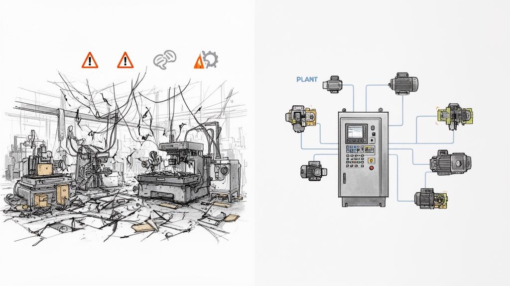
Think of them as the master architect and general contractor for your factory's automation systems, all rolled into one. You’ve got all the best-in-class components—motors from one supplier, drives from another, sensors, PLCs, and sophisticated software. On their own, they're just a pile of expensive parts. The system integrator is the expert team that makes them all talk to each other and work in perfect harmony.
They are the ones who transform a collection of individual pieces of equipment into a single, reliable, and efficient operational powerhouse.
What Does a System Integrator Actually Do?
Let's stick with an analogy. Imagine you're building a custom race car. You've sourced a high-performance engine from Germany, a cutting-edge transmission from Japan, and a complex electronics package from the U.S. They're all top-of-the-line, but they won't work together out of the box.
The system integrator is the specialized engineering crew that designs the custom mounts, writes the control software, and wires everything together. They ensure the engine's raw power is smoothly and reliably translated to the wheels. Without them, you just have a very expensive garage ornament.
In an industrial setting, this role is absolutely critical. An SI bridges the gap between the physical machinery on the plant floor and the software that controls it. They don't just plug in a few cables; they design and build the entire "nervous system" of an operation. This complex job includes everything from programming controllers to fabricating UL-listed electrical panels that safely manage and distribute power.
At its core, the system integrator’s job is to make different, often competing, systems communicate and cooperate seamlessly. They are the specialists who design, build, and implement custom solutions that get your hardware, software, and networks playing nicely together. The fact that the global system integrator market has exploded into a massive industry really speaks to just how essential this function is for modern manufacturing and production.
This concept isn't limited to the factory floor, either. In the business world, a common SI task is connecting a company's customer relationship management (CRM) software with its other business applications. This kind of project ensures that sales data, customer support tickets, and marketing campaigns are all perfectly synchronized. While it's an IT-focused example, the principle is identical: making separate systems work as one cohesive unit. For those interested in that side of things, it's worth understanding CRM integration and app syncing.
Ultimately, whether it's for motors and drives or software and databases, an SI ensures your entire operation runs like a single, intelligent entity.
To put it simply, here’s a quick rundown of their main responsibilities.
System Integrator Core Functions at a Glance
This table breaks down the primary roles of a system integrator, offering a snapshot of their key contributions to any industrial automation project.
Core Function
Description
Example Application
System Design
Creating the complete architectural blueprint for how all hardware and software components will connect and interact.
Designing a control system schematic for a new conveyor line, specifying all PLCs, VFDs, and sensors.
Programming
Writing and testing the custom code that governs the logic and behavior of the automated system (PLCs, HMIs).
Developing the PLC logic that starts and stops motors in a specific sequence based on sensor inputs.
Panel Integration
Building, wiring, and testing the UL-listed electrical control panels that house all the control hardware.
Assembling a NEMA-rated panel with motor starters, circuit breakers, and a PLC for a pump station.
Commissioning
On-site testing and fine-tuning of the entire system to ensure it operates correctly and meets performance specs.
Calibrating motor drive parameters and testing emergency stop functions on the factory floor before going live.
Documentation
Providing comprehensive schematics, user manuals, and maintenance guides for the completed system.
Creating a complete set of electrical drawings and a troubleshooting guide for the maintenance team.
Compliance
Ensuring the system adheres to all relevant safety standards, codes, and regulations (e.g., UL 508A, NFPA 79).
Verifying that all panel wiring and component spacing meet UL standards for certification.
From initial design to final sign-off, a system integrator manages the entire lifecycle of an automation project, making sure every piece fits and functions as intended.
The Critical Roles a System Integrator Plays
So, what does a system integrator actually do? Beyond just connecting a few wires, their real value comes from the specific, hands-on jobs they manage from the first sketch to the final handshake. They're the technical specialists who take a concept on a whiteboard and turn it into a humming, reliable piece of your industrial process.
It’s a step-by-step mission, with each role building on the one before it.
Design and Engineering
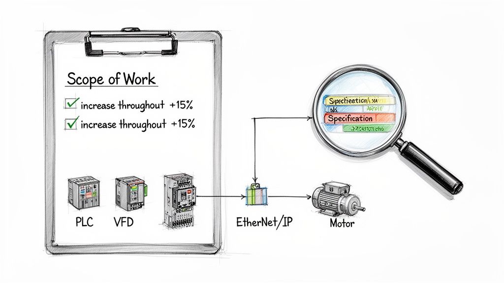
Everything starts with a blueprint. The first thing an integrator does is create the detailed electrical schematics and Piping and Instrument Diagrams (P&IDs). Think of this as mapping out the "nervous system" of your automation process. It's where they define how every motor, sensor, and controller will talk to each other.
For instance, when designing a motor control center, they're not just picking parts off a shelf. They’re specifying every single component, from the variable frequency drives (VFDs) down to the circuit breakers, making absolutely sure the design is safe, efficient, and meets all electrical codes. This upfront engineering is what prevents hugely expensive mistakes down the road.
Programming and Panel Fabrication
With a solid design locked in, the integrator’s team shifts gears. One part of the team starts programming the brains of the operation—the Programmable Logic Controllers (PLCs). This is where custom code is written to run the automation sequences. They also build the intuitive screens for Human-Machine Interfaces (HMIs) and set up the Supervisory Control and Data Acquisition (SCADA) systems that give you a bird's-eye view of the whole plant.
At the same time, their shop technicians are busy with the physical build. This is where the control system really comes to life. They assemble and wire the UL-listed control panels, which are the custom-built enclosures that safely house all the automation gear. In our world, this hands-on hardware integration is a massive part of the job, bridging the gap between a pile of components and a true turnkey solution. A well-integrated system can cut project timelines by 25% and slash downtime by 20%—that's the kind of value we're talking about.
Commissioning and Documentation
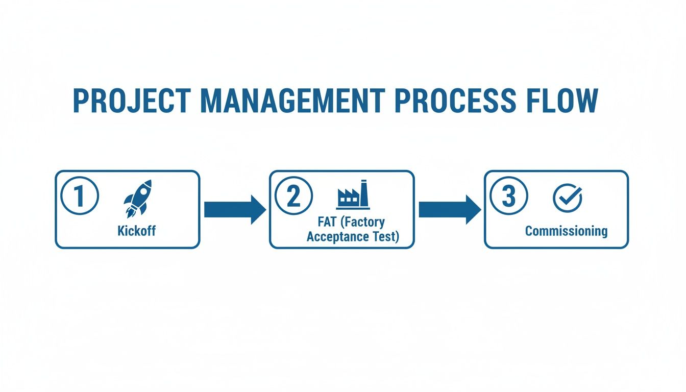
Once the panels are built and the code is written, the integrator packs up and heads to the job site for commissioning. This is where the rubber meets the road. The integrator connects everything on-site, powers up the system, and starts the intense testing process. They’re checking that every motor spins up correctly, every sensor is reading accurately, and all safety circuits work exactly as designed.
Often, they’ll run a Factory Acceptance Test (FAT) at their own shop before the gear ever ships. To get a feel for how detailed this gets, you can check out our comprehensive factory acceptance test checklist. A huge part of an integrator's job is managing these complex installations to make sure everything plays nicely together. For more on that, you can find some great enterprise application integration best practices here.
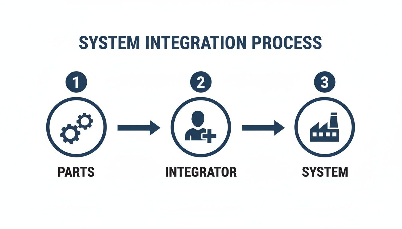
This simple flow shows how an integrator pulls all the individual pieces together into one cohesive system.
As you can see, the integrator is that critical link in the middle, adding the intelligence and assembly needed to turn a box of parts into a working solution.
Finally, they hand over the keys—the complete documentation package. This isn't just a few papers; it includes the as-built electrical drawings, all the program code, operational manuals, and a detailed bill of materials. This binder is your maintenance team's bible, giving them everything they need to troubleshoot and maintain the system for years to come.
Understanding Your Industrial Project Team
On any large industrial project, you’ll find a whole cast of specialists working together. But let's be honest, their roles can get a little blurry. Knowing who does what is absolutely critical to getting the job done right.
To really get a handle on what a system integrator is, it helps to see how they fit in with the other key players you'll find on site, like EPC firms, OEMs, and electrical contractors. Each one owns a distinct piece of the project puzzle. Getting it wrong—like calling a general contractor to program a complex assembly line—can lead to costly delays and a whole lot of frustration.
Distinguishing Key Project Roles
Let’s use an analogy. Imagine you're building a brand new hospital from the ground up.
The Engineering, Procurement, and Construction (EPC) firm is your master developer. They’re looking at the big picture, handling everything from acquiring the land and designing the building to procuring the big-ticket items like MRI machines and HVAC systems. They manage the entire construction process and hand over the keys to a finished hospital.
An Original Equipment Manufacturer (OEM) is the company that actually builds that specialized equipment. They're the experts who engineer and manufacture the high-tech MRI machine or the high-efficiency air handler. Their world revolves around perfecting their product and delivering it as a rock-solid, standalone piece of hardware.
So, where does the system integrator (SI) come in? The SI is the specialist team that brings the hospital’s "central nervous system" to life. They don't pour the concrete or build the MRI machine, but they make that MRI machine talk to the patient record system. They connect the HVAC controls to the building automation software and make sure every critical alarm and data point flows seamlessly to the central nurses' station. Their sole focus is making a bunch of different technologies work together as one smart, cohesive system.
And finally, you have the electrical contractor. These are the skilled tradespeople who physically pull the wire and terminate the connections based on the engineered drawings from the SI or EPC. They're the ones in the trenches installing conduit, landing wires in control panels, and ensuring every physical connection is safe, secure, and up to code.
Key Takeaway: An EPC builds the whole facility. An OEM builds a specific machine. An electrical contractor runs the wires. A system integrator makes all the different machines and software systems talk to each other and work as one.
Comparing Industrial Project Roles
To clear things up even further, this table breaks down the distinct responsibilities of each team. It’s a quick guide to help you figure out who you really need to call for your specific job.
Role
Primary Focus
Typical Scope
Key Deliverable
System Integrator
Making separate automation, control, and software components work together as a single, functional system.
Design, programming, panel fabrication, and commissioning of control systems.
A fully tested and documented, integrated automation solution (e.g., a UL-listed control panel and its programming).
EPC Firm
Managing the entire project lifecycle from concept to completion, covering all disciplines (civil, mechanical, electrical).
Full facility design, procurement of all major equipment, and overall construction management.
A complete, turnkey operational facility or plant.
OEM
Designing and manufacturing a specific piece of machinery or equipment for a specialized function.
The engineering and fabrication of their proprietary equipment.
A standalone, functional piece of equipment (e.g., a pump skid, a CNC machine, a conveyor).
Electrical Contractor
The physical installation, termination, and testing of electrical wiring, conduit, and components.
Running power lines, connecting motors, and wiring panels according to engineered schematics.
A safely installed and code-compliant electrical installation.
While their jobs are different, great projects happen when all these teams communicate and work together smoothly. Understanding who to bring in, and when, is the first step toward a successful outcome.
Real-World Benefits of a System Integrator Partnership
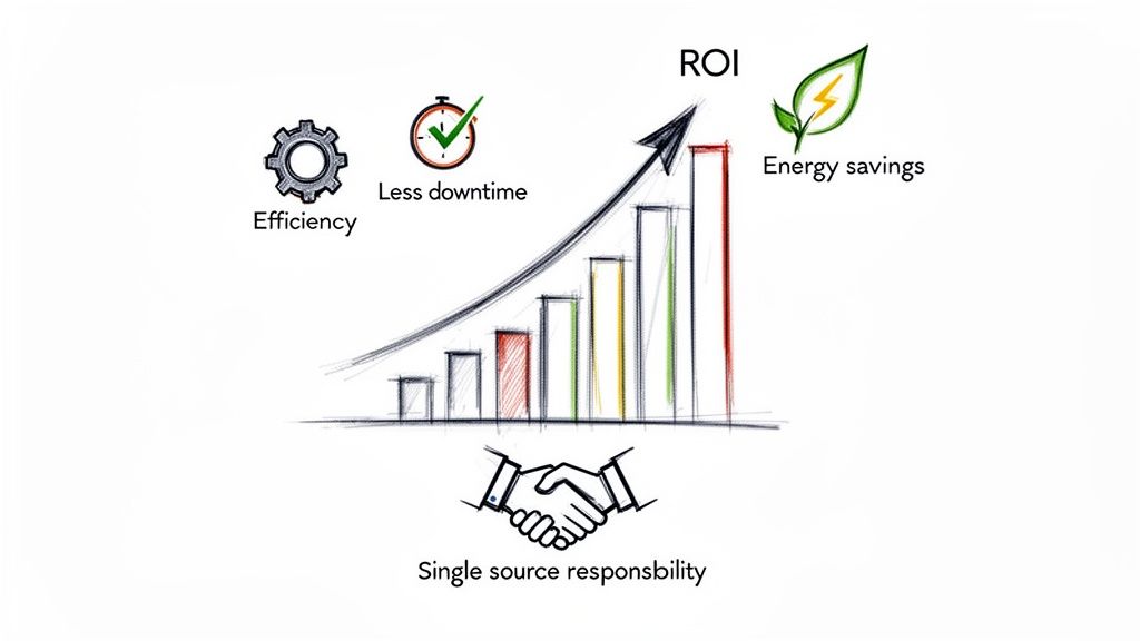
Let's get past the technical jargon for a minute. The decision to bring in a system integrator really boils down to business results. The true return on your investment isn't just in the new panel or the lines of code—it’s in the measurable kick to your bottom line. An expert SI adds value by cutting downtime, boosting efficiency, and getting your project across the finish line faster.
Think about a manufacturing plant constantly dealing with shutdowns because of old, mismatched motor controls. An integrator comes in, designs a modern and unified system, and suddenly things just work. This isn't just about better reliability; it's about real performance gains, like a 20% drop in energy costs and far fewer calls to maintenance.
The real magic is having a single source of responsibility who owns the outcome. It puts an end to the frustrating "blame game" that always seems to pop up between different vendors when something goes wrong.
Driving Efficiency and Slashing Downtime
One of the first things you'll notice after hiring a good SI is a sharp jump in how efficiently your plant runs. When all your components—from the drives to the PLCs—are communicating perfectly, you eliminate the bottlenecks that were secretly killing your productivity. This optimization leads directly to more product out the door and lower costs to make it.
For instance, you might have a heavy-duty conveyor from one OEM and a high-tech packaging machine from another. An integrator is the one who makes them work in sync, like a single, well-oiled machine instead of two separate, clunky steps. That’s the kind of cohesion that stops all those small, recurring delays from eating away at your profits.
A skilled system integrator doesn't just connect boxes; they find hidden efficiencies. By looking at the entire operation, they spot opportunities for improvement that individual equipment vendors would never see, leading to faster cycles and less waste.
The Value of a Single Point of Contact
When you’ve got multiple vendors on a project, figuring out who’s responsible for a problem can be a complete nightmare. Is it a bad sensor, or is it the PLC program? Did the motor starter get sized wrong, or did the electrical contractor miswire something?
A system integrator takes full ownership of the control system. Period. This single point of accountability makes managing the project incredibly simple and ensures you get a cohesive, high-performing result. They're the glue in modern industry, bringing motor control, automation, and power systems together into unified, UL-listed packages that slash inefficiencies. For automation specialists, this means turnkey solutions that can cut commissioning time by 35% while keeping everything up to code. You can learn more about how this single-source approach reduces project risks.
This all-in-one approach gives you a few key advantages:
Accelerated Timelines: With one team managing everything, coordination is seamless and projects get done faster.
Guaranteed Compatibility: The SI makes sure every single component is chosen and programmed to work together without a hitch.
Simplified Support: When you need help, you’ve got one number to call for the entire system. No more runaround.
At the end of the day, partnering with a system integrator is an investment in certainty, efficiency, and a whole lot of peace of mind.
Key Signs That You Need a System Integrator
Knowing when to bring in a specialist can be the difference between a smooth project and one that completely derails. Certain pain points and project milestones are red flags, clear signals that you've hit the limits of what you can handle in-house. Recognizing these signs early helps you get ahead of the problem before it snowballs.
One of the most common triggers is a major facility expansion or a totally new greenfield project. As you scale up, the complexity of your control systems doesn't just add up—it multiplies. An SI provides the crucial big-picture engineering to make sure all your new and existing systems actually talk to each other from day one, helping you avoid the costly, patched-together fixes that so often plague large-scale builds.
When Your Technology Is Working Against You
Another dead giveaway is when you're fighting with unreliable, outdated legacy controls. If your team is constantly putting out fires—troubleshooting random shutdowns or hunting for obsolete parts that just don't exist anymore—it’s a massive drain on your productivity. A system integrator lives and breathes this stuff; they specialize in modernizing these fragile, aging systems into a robust, unified platform that not only works reliably but also gives you valuable data about your operations.
Think about where your equipment comes from, too. If your project involves machinery from a handful of different manufacturers, you’re walking right into a classic integration nightmare. Each OEM delivers a machine that runs beautifully on its own, but getting them all to communicate and operate in a perfectly synchronized sequence? That’s a whole different ballgame.
This is exactly where a system integrator becomes mission-critical. They’re the independent experts who speak the "language" of all the different control platforms, ensuring a machine from Germany plays nice with one from Japan and another from right here in the U.S.
Filling Critical Gaps in Your Team
Sometimes, the need for an SI boils down to your own team's bandwidth and expertise. You might have a fantastic maintenance crew and sharp engineers, but they probably aren’t deep in the weeds of complex PLC programming or designing and building certified control panels every day. A system integrator brings that specialized, niche knowledge to your project without the overhead of hiring a full-time specialist.
Here are a few more tell-tale signs it’s time to pick up the phone:
You Require UL 508A Certified Panels: If your project specs or local inspectors demand UL-certified control panels for safety and compliance, an integrator with a UL 508A panel shop is non-negotiable. There's no way around it.
You Lack Comprehensive Documentation: Are your electrical drawings missing, or so old they look like ancient scrolls? An SI can reverse-engineer your setup and create the accurate documentation you absolutely need for safe and efficient maintenance.
You're Facing Unexplained Inefficiencies: When production is lagging but you can’t figure out why, you've got a bottleneck. An integrator can analyze your entire process, diagnose the weak points, and show you where smarter automation can boost performance.
If any of these scenarios hit a little too close to home, your operation has likely outgrown the do-it-yourself approach. An integrator’s expertise quickly shifts from a "nice-to-have" to a necessity for hitting your production goals safely and efficiently.
How to Choose the Right System Integrator
Picking the right system integrator is easily one of the biggest calls you'll make for your project. Get it right, and you're set up for success. Get it wrong, and you're in for a world of headaches. While technical chops are the price of entry, the best partners bring direct, relevant experience to your facility floor.
Think about it this way: not all integrators are cut from the same cloth. The team that excels at sprawling oil and gas facilities might not be the best fit for the nuanced, high-speed demands of a food and beverage line.
Your first move should always be to screen for industry-specific expertise. An integrator who already speaks your language—understanding the regulations, the operational quirks, and the common pitfalls of your sector—is invaluable. They’ll design a more practical and compliant solution from day one, which saves you from costly do-overs down the road.
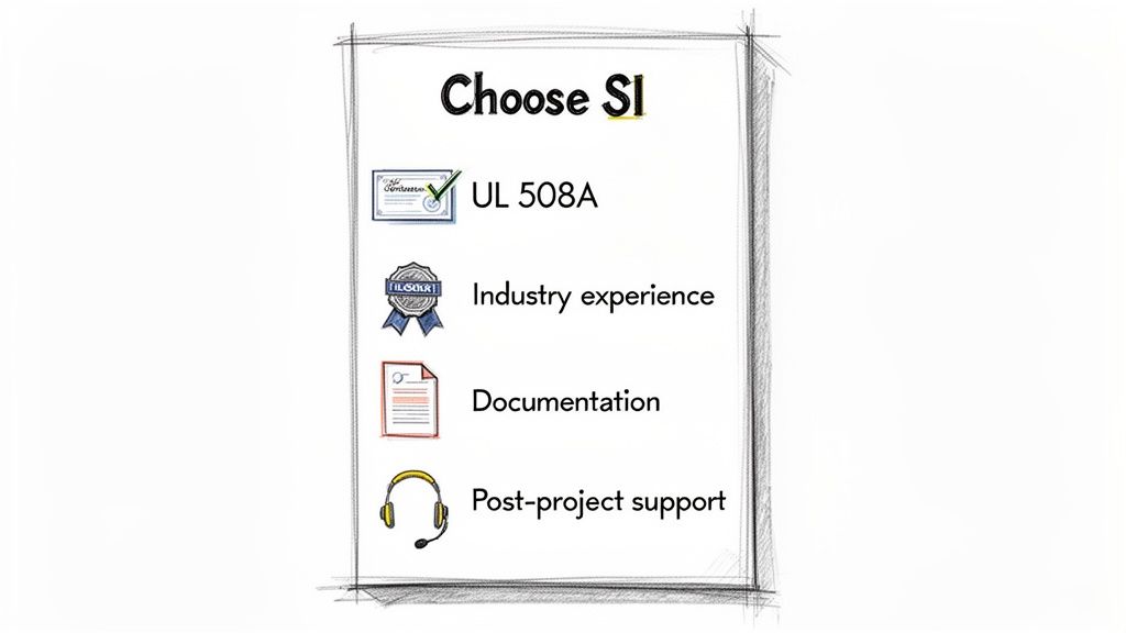
Key Evaluation Criteria
Beyond their resume, you need to look for hard proof of their qualifications and a solid track record. The right partner won't just tell you they're good; they'll show you.
Technical Certifications: First question: is their panel shop UL 508A certified? This isn't just a nice-to-have; it's a critical benchmark for quality, proving their panels meet rigorous safety and construction standards.
Platform Expertise: Do they live and breathe the control platforms you rely on, whether it's Rockwell, Siemens, or something else? Deep knowledge of your tech stack means a smoother integration and makes life easier for your maintenance team for years to come.
Documentation Standards: Don't be shy—ask to see a sample documentation package. A good one will be crystal clear and thorough, with detailed schematics, a complete bill of materials, and well-commented code that your team can actually understand.
Crucial Tip: A truly great system integrator won’t just build what you ask for. They'll push back. They’ll ask the tough questions to get to the root of your problem, acting more like a technical consultant who wants to find the best solution, not just the most obvious one.
Questions to Ask Potential Partners
Once you have a shortlist, it's time to talk. These questions can help you figure out who will be the best fit for your team, both technically and culturally.
How do you handle project communication, especially when scope changes happen?
What does your warranty and post-project support look like in the real world?
Can you walk me through a case study for a project that was a lot like this one?
What's your on-site protocol for safety and risk management?
Making the right choice means looking past the price tag and really digging into the team you’ll be partnering with. For a more detailed checklist, our guide on selecting an industrial automation system integrator offers even more tips. A little due diligence here pays massive dividends, ensuring you get a partner who is locked in on your goals.
Your Top Questions About System Integrators, Answered
Even after you're sold on the idea, some practical questions always pop up. It’s one thing to understand the what, but the how is where the rubber meets the road. Let's tackle the most common questions project managers and engineers ask before pulling the trigger on hiring a system integrator.
How Do Integrators Usually Bill for Their Work?
When it comes to pricing, you'll generally see two main flavors. The first is Time and Materials (T&M), where you're paying for the hours spent on engineering and labor, plus the direct cost of all the parts. This model is great when the project scope is a bit fluid and you need the flexibility to adapt as you go.
The other common approach is a Fixed Price contract. Here, you both agree on a very detailed scope of work for one set price. This gives you budget certainty, which is a huge plus. For longer-term needs, some integrators will also offer support contracts on a retainer basis.
Pro Tip: No matter which model you choose, a crystal-clear, meticulously defined scope of work is your best friend. It’s the single most important tool you have to prevent surprise change orders and make sure everyone is on the exact same page about what gets delivered.
Are System Integrators a Good Fit for Small Companies or OEMs?
You bet. In fact, they can be a game-changer. For smaller businesses or Original Equipment Manufacturers (OEMs), bringing on an integrator is like getting access to a world-class engineering team without the hefty price tag and overhead of hiring full-time specialists.
Think about an OEM that builds great machinery. They can partner with an integrator to design, standardize, and build certified UL 508A control panels for their entire product line. This move not only boosts product quality and consistency but also makes their equipment far more marketable by taking complex electrical compliance off their plate. It lets the OEM stick to what they do best—mechanical design—while the integrator handles all the controls.
What Kind of Support Can I Expect After the Project Is Done?
A good system integrator doesn't just pack up their tools and disappear once the system is running. The best ones see the project handover as the start of a partnership, not the end of a transaction. Post-project support should be a standard part of their offering and something you define clearly in the contract.
This support can look like a few different things. It might be a standard warranty period for bug fixes, or it could be a full-blown service level agreement (SLA) that covers everything from 24/7 remote support and preventive maintenance checks to future system upgrades. Always get the details on the level and length of support ironed out before you sign anything.
At E & I Sales, we’re more than just a component supplier; we're your partner in building fully engineered, turnkey solutions. From custom UL-listed control panels to complete system commissioning, we act as the single point of contact to make sure your automation projects get done right. Learn how our integration services can accelerate your next project.
Ever wondered how a massive chemical plant or a sprawling manufacturing facility runs with such clockwork precision? The secret isn't magic—it's process control and instrumentation.
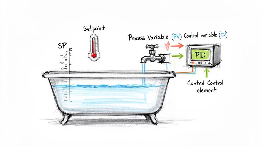
Think of it like the cruise control in your car. You decide you want to go 65 MPH; that's your target, or Setpoint. The car's system constantly reads your actual speed from the speedometer—the Process Variable. If you start going uphill and slow down, the system detects this and automatically gives the engine more gas—the Control Variable—to get you back to 65 MPH. No hands, no feet, just a simple, continuous loop of measuring, comparing, and adjusting.
That same feedback loop is the beating heart of modern industry. From refining oil to bottling beverages, the goal is always to keep critical variables like temperature, pressure, or flow within a tight, optimal range. It’s all about guaranteeing product quality, boosting efficiency, and, most importantly, keeping operations safe.
The Three Core Elements of a Control Loop
Every automated control system, no matter how complex, boils down to three fundamental components. Get these, and you've got the foundation for understanding the entire field.
We can break down these core elements using our cruise control analogy, which makes it easy to see how they apply in a real-world industrial setting.
The Three Core Elements of a Control Loop
Component
Industrial Example
Cruise Control Analogy
Process Variable (PV)
The current temperature inside a furnace.
The actual speed shown on your speedometer.
Setpoint (SP)
The target temperature of 150°C for a chemical reaction.
Your desired speed of 65 MPH.
Control Variable (CV)
The gas valve opening or closing to adjust the furnace's flame.
The throttle adjusting the engine's power.
At the end of the day, a well-designed control loop is all about minimizing the difference—the "error"—between what's actually happening (the PV) and what you want to happen (the SP). This constant, tiny correction is what keeps massive, complex industrial processes stable and predictable.
Why This Matters in the Real World
This isn't just an academic exercise; it's big business. The global process automation and instrumentation market was recently valued between USD 74.45 billion and USD 81.05 billion, with major growth on the horizon. That boom is fueled by a relentless demand for better efficiency, tighter safety protocols, and lower operating costs across every sector imaginable.
Whether it’s getting the mix just right in a pharmaceutical batch or managing precise gas flows for heat treatment, as detailed in this piece on Process Control Heat Treatment Gas Analysis Solutions, the core principles remain the same.
By mastering the relationship between PV, SP, and CV, engineers and technicians can design and maintain the incredibly robust systems that power our world. If you're ready to see the hardware that makes this all possible, our guide to industrial controls and automation is the perfect next step. A solid grasp of these fundamentals is your key to understanding the more advanced strategies and tools that bring modern industry to life.
The Four Pillars of Industrial Instrumentation
Think of an industrial control system like a human nervous system. You have parts that sense the world, parts that send messages, a brain that makes decisions, and muscles that take action. This is the core idea behind all process control and instrumentation—an interconnected network of hardware that keeps things running smoothly.
These components aren't just a random collection of parts; they form a constant, looping conversation. The quality of each piece in that loop has a direct impact on how well the whole system performs. Let's break down the four essential pillars to see how they work together.
Sensors: The Senses of the Process
First up, and arguably the most fundamental, is the sensor. This is the device that's right there in the thick of it, acting as the system's eyes and ears. Its only job is to measure a specific physical property—what we call the Process Variable (PV)—and turn it into a signal the rest of the system can understand, usually an electrical one.
Picture a massive mixing tank in a food plant. A level sensor sitting in the liquid is constantly reporting how full that tank is. In a furnace, a thermocouple is measuring the heat. On a gas pipeline, a pressure sensor is keeping tabs on the force inside. Without good sensors, your control system is flying blind.
Transmitters: The Nerves Sending the Signal
Once the sensor gets a reading, that raw data has to travel to the system’s brain. That's where the transmitter comes in. It takes the tiny, often fragile signal from the sensor, cleans it up, boosts it, and converts it into a standardized signal that can survive a long trip through a noisy industrial plant without getting garbled.
The industry workhorse for this is the 4-20 mA analog signal. In this setup, 4 mA might mean the tank is empty, and 20 mA means it's full. This universal language ensures that a controller from one company can perfectly understand a sensor from another. The transmitter is the critical nerve fiber connecting the senses to the brain.
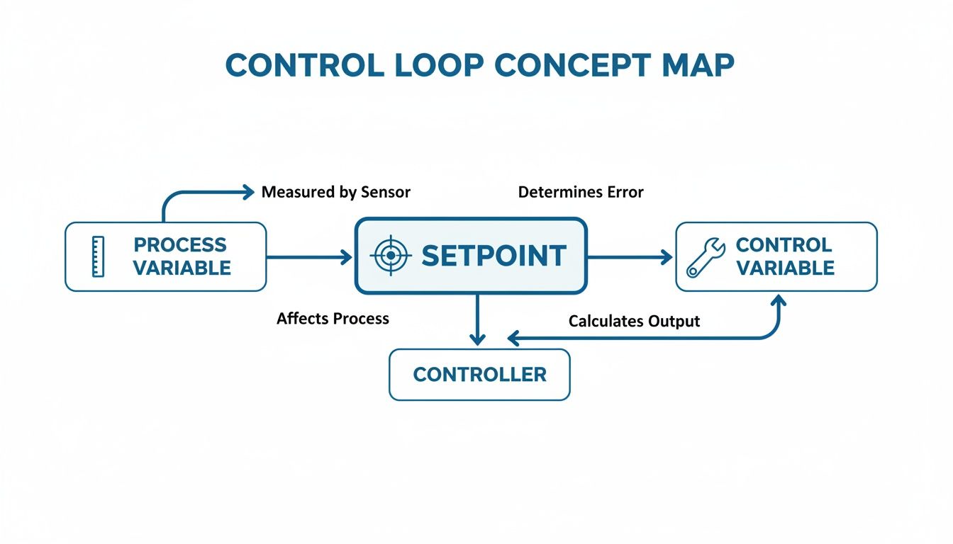
This concept map shows you exactly how that Process Variable, measured by the sensor and sent by the transmitter, fits into the bigger picture of the control loop.
As you can see, it's a constant cycle: measure, compare, and correct.
Controllers: The Brain Making Decisions
The controller is the central command center of the whole operation. It receives that clean, standardized signal from the transmitter and does the most important job of all: it thinks. It takes the incoming Process Variable (PV) and compares it to the target value—the Setpoint (SP)—that an operator has programmed in.
Based on the difference, or "error," between what is happening and what should be happening, the controller calculates the right move. This "brain" is usually a Programmable Logic Controller (PLC) or a component within a larger Distributed Control System (DCS).
The controller is where all the logic lives. And getting the housing for this brain right is just as important as the logic itself, a topic we cover in our guide to industrial control panel design.
Final Control Elements: The Muscles Taking Action
A decision is worthless if you can't act on it. The last piece of the puzzle is the Final Control Element (FCE), which acts as the muscle of the system. It takes the command from the controller and physically changes something in the process to get that Process Variable back in line with the Setpoint.
This is where the rubber meets the road. The FCE is the part doing the actual work, and it can take many forms:
A control valve that opens or closes a little more to adjust the flow of a liquid.
A heating element in an oven that kicks on to bring the temperature up.
A Variable Frequency Drive (VFD) that speeds up or slows down a motor running a pump.
Put them all together—Sensor, Transmitter, Controller, and Final Control Element—and you have a closed-loop system that is constantly measuring, comparing, deciding, and acting. This simple but powerful architecture is the bedrock of modern industrial automation, making sure processes run safely, efficiently, and with incredible consistency.
Choosing the Right Process Control Strategy
Once your physical hardware is in place, the game shifts from the "what" to the "how." The control strategy is the brain of the operation—it’s the logic your controller uses to hit and hold your target setpoint. Getting this right is what separates a system that constantly fights you from one that runs with clockwork precision.
The undisputed champion in the world of process control and instrumentation is PID control. It’s no exaggeration to call it the workhorse of automation; over 90% of industrial control loops rely on some flavor of it. Its real power comes from its elegant approach to managing a process by looking at the past, present, and future all at once.
PID Control: The Industry Standard
Let's use a simple, everyday task: filling a bathtub. You want the water to hit a specific level at just the right temperature. This familiar chore is a perfect way to understand the three parts of PID (Proportional-Integral-Derivative) control.
Proportional (P): This is your gut reaction. The tub is empty, so you crank the faucet on full blast. As the water level (your Process Variable) gets closer to where you want it (the Setpoint), you start to ease back on the handle. The P-action is a direct response to the current error—the bigger the gap, the bigger the reaction.
Integral (I): This part corrects for stubborn, lingering errors. Maybe your water pressure is a little low, and the tub is filling slower than it should. The I-action remembers this sluggishness and nudges the valve open just a bit more to make up for it, wiping out that small, persistent gap.
Derivative (D): This is all about looking ahead. As the water level surges toward your target, you start turning the faucet off before it gets there. Why? To keep it from overflowing. The D-action looks at how fast things are changing and pumps the brakes to prevent overshooting the target.
By carefully tuning these three elements, a PID controller delivers incredibly stable and reliable command over everything from motor speeds to the temperature inside a chemical reactor.
Advanced Strategies for Complex Challenges
While PID is a fantastic all-rounder, some processes have tricky variables that demand a more sophisticated game plan. For those tougher jobs, engineers bring in strategies like Cascade and Feedforward control for even tighter regulation.
Cascade Control: Manager and Worker Logic
Think about a situation where one variable has a huge, immediate impact on the one you actually care about. A great example is controlling the temperature of a product inside a jacketed reactor. Your main goal is the product temperature (primary variable), but it's directly affected by the jacket temperature (secondary variable).
Cascade control creates a smart "manager-and-worker" setup. The primary controller (the manager) watches the final product temperature. But instead of messing with the steam valve directly, it tells a secondary controller (the worker) what the jacket temperature should be.
This two-loop structure is brilliant at shutting down disturbances before they cause trouble. If steam pressure suddenly fluctuates, the nimble "worker" loop corrects the jacket temperature long before the product temperature even has a chance to drift.
Feedforward Control: Playing Offense Against Disturbances
Feedforward control is all about being proactive, not reactive. It works by spotting a potential disturbance before it hits your process and making a correction ahead of time.
Imagine you’re heating cold liquid as it flows into a tank. If that incoming flow suddenly doubles, a standard feedback controller won't do anything until it sees the tank's overall temperature start to drop.
A feedforward system, on the other hand, is much smarter:
It measures the incoming flow rate (the disturbance).
It instantly calculates how much more steam is needed for that extra liquid.
It opens the steam valve wider at the exact same moment the flow increases.
This anticipatory move slashes the impact of the disturbance, keeping your process remarkably stable. For large-scale systems, understanding these different architectures is critical, a topic we dive into deeper in our breakdown of SCADA vs DCS. Ultimately, choosing the right logic—whether it's the foundational PID or a more advanced strategy—is the key to a responsive, efficient, and reliable control system.
How Control Systems Communicate with Each Other
A control system is only as smart as the information it can share. All the individual sensors, controllers, and actuators we’ve covered don't work alone—they're in a constant, high-speed conversation that keeps an entire facility running in perfect sync. This network is the nervous system of modern process control and instrumentation.
It wasn't always this easy. In the past, every single sensor and valve needed its own dedicated pair of wires running all the way back to a central control panel. Can you imagine the sheer amount of copper required for a plant with thousands of measurement points? It was an absolute beast to install, incredibly expensive, and a complete nightmare to troubleshoot. One bad wire could bring a critical process to a halt, sending technicians on a hunt through massive, identical cable bundles.
Thankfully, we've moved on. Today’s industrial communication is built on rugged, sophisticated digital networks, much like your office internet but designed to withstand the tough environment of a factory floor. These networks have dramatically cut wiring costs, simplified installations, and opened the door to powerful new diagnostic tools.
The Brains of the Operation: PLCs and DCS
At the heart of this communication web, you'll find the main controllers—usually a Programmable Logic Controller (PLC) or a Distributed Control System (DCS). These are the mission control centers, the air traffic controllers directing every signal in the plant.
PLCs are the sprinters, often used to manage individual machines or smaller, lightning-fast processes. They’re masters of discrete logic, like turning a conveyor belt on or off in a split second. A DCS, on the other hand, is the marathon runner, built to manage sprawling, continuous processes across an entire facility. It brings thousands of control loops together into a single, cohesive command center for operators.
Whether it’s a PLC or a DCS, these controllers act as the central hub, gathering data, running the control logic, and sending commands back out to the field. Their ability to speak the right "language" is what makes it all work.
The real magic is in the communication protocols. Think of them as the agreed-upon languages and grammatical rules that let different devices understand one another. Just like humans use English or Spanish, industrial devices use protocols to exchange information clearly and without fail.
Picking the right protocol is a huge decision. It affects everything from system speed and future scalability to how easily you can upgrade your equipment down the road.
Understanding Industrial Communication Protocols
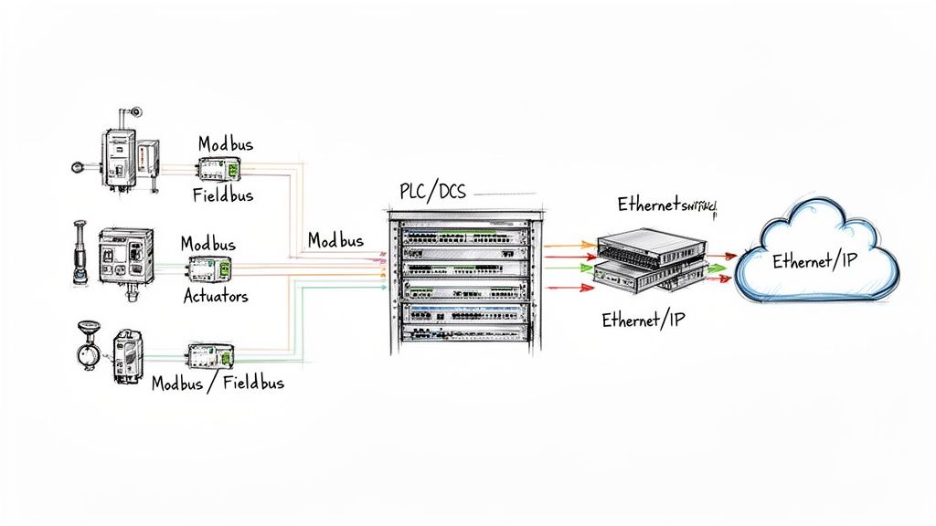
Over the years, a whole zoo of protocols has emerged to solve different industrial challenges. While there are many out there, a few have become the undisputed industry standards because they're reliable, well-supported, and just plain work. Getting a handle on the differences between a workhorse like Modbus and a modern powerhouse like EtherNet/IP is crucial.
A quick look at the major players helps paint the picture. Each protocol was designed with a specific job in mind, and knowing their strengths is key to building a robust network.
Comparing Common Industrial Communication Protocols
Protocol
Primary Use Case
Key Advantage
Modbus
Simple device communication, connecting basic sensors/meters to a PLC.
Extremely simple, universally supported, and easy to implement.
Fieldbus (FOUNDATION, Profibus)
Complex process control, connecting "smart" instruments.
Allows two-way communication and advanced diagnostics over a single pair of wires.
EtherNet/IP
High-speed, plant-wide networking and enterprise integration.
High bandwidth, uses standard Ethernet hardware, and seamlessly connects the factory floor to business systems.
Here's a breakdown of what that means in the real world:
Modbus: Developed way back in 1979, Modbus is the granddaddy of them all. It’s a simple, tough master-slave protocol where one device (the master) asks another (the slave) for its data. It’s not the fastest, but its simplicity makes it a rock-solid choice for basic device connections.
Fieldbus (FOUNDATION Fieldbus & Profibus): These protocols were a massive leap forward. They allowed multiple devices to share the same two wires, but more importantly, they introduced true two-way communication. Suddenly, a smart valve could send back not just its position, but detailed diagnostic data about its own health.
EtherNet/IP: This protocol uses the same technology that powers your office computers and the internet. EtherNet/IP brings incredible speed and bandwidth to the factory floor, allowing control data, diagnostics, and even corporate data to travel on the same network. It's the standard for modern automation for a reason.
These networks provide game-changing benefits. You're looking at drastically less wiring, faster project commissioning, and the power to diagnose a failing sensor from a control room miles away. Whether you're designing a single UL-listed control panel or an entire plant network, a solid grasp of these communication fundamentals is non-negotiable for building a resilient, scalable operation.
Meeting Critical Industry Standards and Compliance
In the world of process control and instrumentation, a clever design is only half the story. For a system to be safe, reliable, and insurable, it absolutely has to play by the rules—and those rules are written in the language of industry standards and codes.
Think of these standards not as suggestions, but as a critical framework. They ensure every component talks to each other correctly, installations won't create hazards, and your entire operation is compliant from day one. Navigating this landscape means getting familiar with a few key players.
You have organizations like the International Society of Automation (ISA), which sets the universal language for things like instrumentation diagrams (P&IDs). Thanks to them, an engineer in Texas and an engineer in Germany can look at the same drawing and know exactly what they’re seeing.
Then there’s the National Electrical Code (NEC), which is all about the hands-on, practical side of the job. It governs the safe installation of all electrical equipment, from how you route a cable to how you ground a panel. Following the NEC isn't just good practice; it's a legal requirement that inspectors enforce to prevent fires and electrical accidents.
The Gold Standard for Control Panels: UL 508A
While the ISA and NEC set the broad stage, the UL 508A certification puts a laser focus on one of the most vital parts of any system: the industrial control panel. This standard from Underwriters Laboratories is the undisputed benchmark for safety and quality in North America.
A UL 508A sticker on a control panel isn't just for show. It’s a declaration that the panel was designed and built to a strict, independently verified set of safety rules. It means every single component inside was chosen, sized, and wired correctly for its specific job.
Partnering with a UL 508A certified panel shop brings some serious, non-negotiable advantages to the table:
Guaranteed Compliance: A UL-listed panel sails through inspections. It's pre-certified to meet national safety standards, which saves a massive amount of time, money, and headaches when the local Authority Having Jurisdiction (AHJ) shows up.
Real-World Safety: The standard is all about the details that prevent disaster—things like proper component spacing to avoid overheating, correct short-circuit current ratings (SCCR), and wiring techniques that protect people from shock and arc flash.
Reduced Liability: If something ever does go wrong, that UL 508A certification is documented proof that you did your due diligence. It shows a clear commitment to safety and is invaluable for any insurance claim or legal review.
Making sure your control panels are built to these standards is a foundational decision. It ensures the "brain" of your system is not just doing its job, but is fundamentally safe, reliable, and built for the long haul. For any serious industrial operation, UL 508A isn't a feature—it's a requirement.
The Future of Industrial Automation Technology
The world of process control and instrumentation is changing, and it's happening fast. We're moving beyond the simple feedback loops that have been the standard for decades and stepping into a new era of smart, predictive, and deeply connected operations. While the core job of measuring and correcting a process isn't going away, the tools we use to do it are becoming incredibly powerful. It’s all about getting industrial facilities ready not just for today, but for whatever comes next.
The engine driving this shift is the Industrial Internet of Things (IIoT). The best way to think about IIoT is that it gives a voice to every single component in your plant—every motor, every valve, every sensor. Instead of just getting a basic 4-20 mA signal, smart instruments can now pour out a ton of diagnostic data over industrial networks. This gives you a level of visibility into the health of your process that was unimaginable just a few years ago.
The Rise of Predictive Maintenance
All this new data unlocks one of the biggest game-changers for modern industry: predictive maintenance. For years, maintenance has been stuck in two inefficient modes. You either fix things after they break (reactive), or you replace parts on a rigid schedule, whether they need it or not (preventative). Both approaches cost you, either in surprise downtime or in wasted parts and labor.
Predictive maintenance flips that script completely. By analyzing live data from IIoT sensors—things like a tiny shift in a motor's vibration or a pump's temperature creeping up by a few degrees—these systems can spot the warning signs of failure weeks or even months out.
This lets your maintenance team switch from a "fail and fix" model to a "predict and prevent" strategy. Instead of getting a frantic call about a catastrophic failure at 3 AM, you can schedule the repair during planned downtime. That's a massive saving in both time and money.
AI and Advanced Process Control
But it’s not just about preventing failures; this new wave of tech is making the processes themselves smarter. Advanced Process Control (APC) systems use artificial intelligence and machine learning to fine-tune operations in ways a standard PID controller just can't match. An APC system can look at hundreds of variables at once, learning the incredibly complex relationships between them to make constant, tiny adjustments.
What does that mean for the bottom line? Huge improvements in:
Yield: Squeezing the maximum amount of high-quality product out of your raw materials.
Energy Efficiency: Cutting down power consumption by running equipment at its absolute sweet spot.
Product Consistency: Tightening up variability to make sure every single batch meets spec perfectly.
This isn't just a niche trend; it's a market-wide shift. The entire process automation market is being reshaped by IIoT and advanced digital tools. Solutions built on predictive maintenance and APC are seeing the fastest growth, signaling that integrators have to move beyond just offering the same old services.
As we look ahead, bringing these technologies into the fold isn't just a simple upgrade—it's a fundamental change in how we think about running an industrial plant. Building systems ready for this connected future is the only way to stay competitive. For a deeper dive, you can learn more about AI enablement in industrial automation and robotics.
Got Questions? We've Got Answers.
When you're deep in the weeds of process control and instrumentation, a few key questions always seem to pop up. Whether you're comparing system architectures or justifying a component choice, getting straight answers is crucial. Here are some of the most common things we hear from engineers and technicians out in the field.
What’s the Real Difference Between a PLC and a DCS?
This is a classic. Think of it this way: a Programmable Logic Controller (PLC) is a sprinter, built for the fast, repetitive tasks of a single machine or a small, self-contained process. It's the go-to for controlling a conveyor system or a packaging line with lightning-fast, on/off logic.
A Distributed Control System (DCS), on the other hand, is a marathon runner. It’s designed to manage and orchestrate an entire plant, like a chemical refinery, with thousands of different control points all working together. It’s all about continuous control, providing a single, unified view for operators. While the lines are blurring a bit, the core idea holds: PLCs are for machine-level automation, and a DCS is for large-scale process orchestration.
How Do I Pick the Right Sensor for the Job?
Choosing the right sensor is everything—get it wrong, and nothing else matters. It really boils down to matching the tool to the specific task and environment.
What are you measuring? Is it pressure, temperature, flow, level, or something else? Start here.
What’s the environment like? Think about corrosive chemicals, extreme temperatures, high pressure, or constant vibration. The sensor has to survive where it lives.
How accurate do you need to be? Getting a super-precise reading is great, but it costs more. Don't pay for accuracy you don't actually need for the process.
What about the physical space? Will it be exposed to moisture? Does it need to be rated for a hazardous location?
Getting an expert opinion here is smart. It helps you find that sweet spot between performance, lifespan, and cost. You can avoid overspending on features you don’t need or, worse, having a cheap sensor fail and take your whole process down with it.
Why Does a UL 508A Certification Matter So Much?
Seeing that UL 508A sticker on a control panel is a big deal, and for good reason. It’s not just a label; it’s proof that the panel was built to rigorous, nationally recognized safety standards from Underwriters Laboratories. It’s the benchmark that inspectors and regulators look for.
A UL-certified panel means the right components were used, the wiring was done correctly, and all the essential safety features are in place. This is absolutely critical for protecting your team from shock and arc flash, preventing expensive equipment from getting fried, and making sure your facility is up to code. Simply put, it's a non-negotiable seal of safety and reliability.
At E & I Sales, we live and breathe this stuff. We specialize in designing and building UL-listed control panels that serve as the safe, reliable heart of industrial systems.
A vacuum circuit breaker, or VCB, is an electrical protection device that uses a perfect vacuum to extinguish an electrical arc. Think of it as an incredibly fast, ultra-reliable firefighter for your medium-voltage electrical system. It's designed to stop a destructive fault current in its tracks—in just milliseconds—to protect your most vital equipment.
This sealed, zero-maintenance design has made the VCB the undisputed gold standard for industrial power distribution today.
So, What Does a Vacuum Circuit Breaker Actually Do?
Picture your plant's power system as a network of superhighways, all carrying immense electrical current. A short circuit or overload is like a catastrophic, multi-car pile-up. It happens in an instant and brings everything to a grinding halt, causing widespread damage. The vacuum circuit breaker is your advanced, automated traffic controller and emergency response unit, all rolled into one.
Its main job is to act as a silent guardian for your most critical and expensive assets—think large motors, transformers, and switchgear. Under normal operating conditions, it just stays closed, letting power flow right through it without any interruption. But the second a fault is detected, it springs into action with unbelievable speed.
A Mission-Critical Fail-Safe
The VCB’s core purpose is to interrupt the flow of dangerous fault currents. This is absolutely critical for preventing a few key disasters:
Catastrophic Equipment Damage: A short circuit can unleash thousands of amps of energy, enough to literally melt the windings in a motor or completely destroy a transformer. A VCB isolates that fault before the real damage is done.
Widespread Outages: By tripping only the affected part of the system, it keeps a single fault from cascading into a facility-wide blackout.
Serious Safety Hazards: Uncontrolled electrical arcs can cause violent explosions and fires, putting your personnel at severe risk. The VCB contains and extinguishes that arc energy safely within its sealed chamber.
The Power of Nothing
What makes a VCB so remarkably effective is its use of a vacuum. An electrical arc is essentially a superheated plasma that needs a medium—like air or gas—to keep burning. By separating its electrical contacts inside a perfectly sealed vacuum chamber, the VCB creates an environment where an arc simply can't survive.
A vacuum is the ultimate electrical insulator. Once the contacts inside a vacuum circuit breaker separate, the arc is starved of fuel and extinguishes almost instantly as the AC current passes through its natural zero point.
This simple principle is what allows the VCB to quench an arc with extreme speed and with minimal wear and tear on its internal parts. Unlike older technologies that relied on messy oil or complex compressed air systems, the vacuum interrupter is a "sealed for life" component. It requires practically no maintenance over its entire 20- to 30-year lifespan.
This unmatched reliability and low total cost of ownership is exactly why VCBs have become the go-to choice for modern industrial applications, from manufacturing plants to data centers and everything in between.
How a Vacuum Interrupter Works
At the very core of every vacuum circuit breaker, you'll find its most vital component: the vacuum interrupter. This is the sealed, maintenance-free chamber where the real magic happens—where electrical arcs are extinguished with incredible speed. To really get why VCBs are so dependable in tough industrial environments, you first have to understand what goes on inside this little chamber.
The concept is brilliantly simple but unbelievably effective. The interrupter has just three main parts: a fixed electrical contact, a moving electrical contact, and the hermetically sealed vacuum chamber that houses them. That vacuum is what makes all the difference.
The Power of an Empty Space
Think about what happens if you try to light a match in outer space. It fizzles out instantly. Why? No oxygen. An electrical arc is a lot like that flame; it’s a superheated plasma that needs a medium—like air or some other gas—to keep burning.
By creating an environment with practically no air molecules, the vacuum interrupter literally starves the arc of the fuel it needs to exist. This simple principle gives it a massive dielectric strength (its ability to insulate against voltage) that is far greater than air or even specialized gases like SF6 at normal pressure.
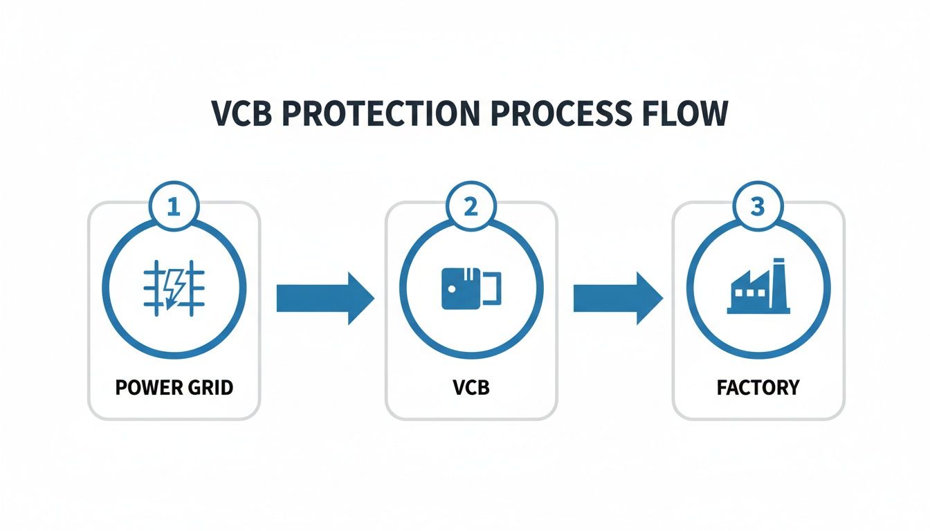
This flow diagram shows how a VCB acts as a gatekeeper, protecting a facility from grid-side problems.
You can see its role in isolating all the downstream equipment from upstream faults, which is critical for keeping operations safe and running smoothly.
The Arc Interruption Sequence Step-by-Step
When a fault hits the system, a precise, lightning-fast chain of events kicks off inside the interrupter. The whole show is over in a few milliseconds, usually within just 3 to 5 cycles of the AC waveform.
Fault Detected, Trip Signal Sent: Protective relays sense the abnormal current from a short circuit or overload. They waste no time, sending a trip signal to the VCB's operating mechanism.
Contacts Separate: The mechanism yanks the moving contact away from the fixed one. As they part, current is forced to jump the widening gap, and an electrical arc is born.
Metal Vapor Plasma Forms: The arc is intensely hot, instantly vaporizing a tiny amount of metal from the contact surfaces. This creates a temporary, conductive bridge of metal vapor plasma, which allows current to flow for just a moment longer.
Current Zero Extinction: This is where the vacuum really flexes its muscle. The AC current waveform naturally drops to zero 120 times every second on a 60Hz system. The moment the current hits zero, the arc has no energy to sustain itself. And because there’s no gas in the chamber to help it reignite, it's extinguished for good.
The vacuum's ability to regain its full dielectric strength almost instantly after the current hits zero is the key. It prevents the arc from ever re-striking. This makes the interruption incredibly clean, fast, and efficient, which minimizes wear and tear on the contacts.
Why This Process Is Superior
The entire event is neatly contained inside the sealed interrupter. There are no external flames, no deafening bang, and no venting of hot gases, making the whole operation incredibly safe.
Better yet, because the arc is so short-lived, the contacts barely erode. This means a single vacuum interrupter can perform thousands of operations without ever needing to be serviced. It's this simple, elegant process that has cemented the VCB's reputation for unmatched speed, reliability, and safety—protecting critical industrial assets with near-perfect precision.
Demystifying VCB Ratings and Specifications
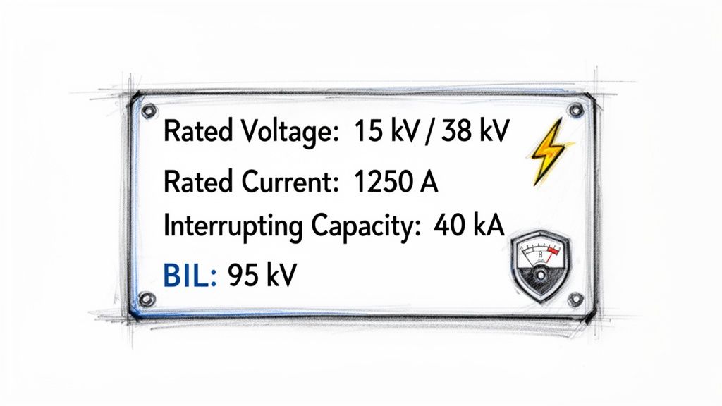
Choosing a vacuum circuit breaker isn’t like picking a part off a shelf. You're matching a critical safety device to the very specific electrical heartbeat of your facility. Think of a VCB's nameplate as its resume—it's packed with the technical specs that spell out exactly what it can and can't do. Getting this right is fundamental to protecting your people and your high-value assets.
These ratings aren't just arbitrary numbers. They are firm promises about the breaker's performance, guaranteeing it can handle not only the daily grind but also the worst-case fault scenarios without skipping a beat.
The Core Electrical Ratings You Can't Ignore
While a full data sheet can look intimidating, a few key specifications are absolutely non-negotiable. These are the cornerstones of any solid VCB selection.
Rated Voltage (kV): This is the maximum voltage the breaker is built to handle safely. You'll see standard ratings like 15kV and 38kV, which line up with common medium-voltage distribution systems. Using an underrated breaker is a direct path to insulation failure.
Continuous Current (Amps): This tells you how much current the breaker can carry day in and day out without overheating. This figure must be higher than the normal full-load current of the circuit it’s protecting. For a deeper dive, check out our guide on proper circuit breaker sizing.
Interrupting Current Capacity (kA): This is arguably the most critical safety rating on the entire nameplate. It's the absolute maximum fault current the VCB can extinguish safely. If your system can produce a 40kA fault and your breaker is only rated for 25kA, you’re looking at a potential explosion, not a clean trip.
A great way to think about the interrupting rating is to compare it to firefighting equipment. You wouldn't bring a small fire extinguisher to a five-alarm building fire. The interrupting capacity ensures your breaker has enough "firepower" to safely put out the most violent electrical fire your system could ever throw at it.
Digging Deeper: Specs That Define Reliability
Beyond the big three, a few other specifications paint a clearer picture of how a VCB will hold up in the real world. These details help you fine-tune your choice for specific applications, making sure the breaker doesn't just work on day one, but for years to come.
Basic Insulation Level (BIL): Measured in kV, this rating signals the breaker's ability to survive a massive, lightning-fast voltage surge, like from a lightning strike. A higher BIL rating means tougher insulation and better protection against transient events.
Operating Duty Cycle: This spec defines the breaker's ability to perform a sequence of reclosing operations. A standard duty cycle like "O – 0.3s – CO – 3min – CO" lays out the exact sequence of open (O) and close-open (CO) operations it can handle without sustaining damage.
The market for this technology underscores just how important these specs are. The medium-voltage outdoor vacuum circuit breaker market is already valued at USD 609.37 million and is expected to more than double to USD 1205.29 million by 2032. The 15kV to 27kV segment is the dominant force, holding a 40.24% market share—a perfect fit for the industrial motor control centers and manufacturing plants that rely on them. Understanding these ratings means you’re specifying the right gear for these critical, growing applications.
Comparing VCB and SF6 Circuit Breakers
When you're specifying a medium-voltage breaker, the choice often comes down to a head-to-head matchup between two heavyweights: the vacuum circuit breaker (VCB) and the SF6 (sulfur hexafluoride) circuit breaker.
While both are pros at snuffing out fault currents, they get the job done in fundamentally different ways. These differences have massive implications for your facility's environmental impact, maintenance schedule, and long-term operational costs. Getting this right is about future-proofing your plant.
At the heart of it all is the arc-quenching medium. A VCB uses a pure vacuum—literally, nothing—to extinguish the electrical arc. On the other hand, an SF6 breaker uses sulfur hexafluoride gas, a man-made compound with incredible dielectric properties. This single difference is the domino that sets off every other point of comparison.
Environmental Impact and Sustainability
The environmental report card for these two technologies couldn't be more different. Vacuum interrupters are completely benign. The sealed vacuum chamber contains zero harmful substances and poses no threat to the atmosphere. If a VCB’s interrupter ever fails, it simply loses its vacuum. No harm, no foul.
SF6, however, is a whole other story. It’s the most potent greenhouse gas on the planet, with a global warming potential 24,300 times higher than carbon dioxide. That's not a typo. Any leak from SF6-filled equipment releases this incredibly powerful gas straight into the atmosphere, directly contributing to climate change. This massive environmental risk has regulators scrambling, with the EU already implementing a phased ban on SF6 in new switchgear.
Maintenance and Operational Demands
When it comes to maintenance, the paths diverge significantly, hitting your total cost of ownership right where it counts. The vacuum circuit breaker is legendary for its hands-off, low-maintenance design.
VCB Maintenance: The vacuum interrupter is a "sealed for life" component. That means no gas monitoring, no refilling, and no special handling. Maintenance is all about the mechanicals—the operating system—which just needs routine cleaning, lubrication, and electrical testing.
SF6 Maintenance: SF6 breakers are much more demanding. They require constant vigilance, with periodic checks of the gas pressure to spot leaks and make sure insulation levels are correct. Handling the SF6 gas itself requires specially trained technicians and specific equipment to avoid releasing it into the atmosphere.
This stark contrast is a huge driver behind market trends. The global power distribution vacuum circuit breaker market, currently valued at USD 3.8 billion, is forecasted to skyrocket to USD 9.0 billion by 2035. Why the boom? It’s all about the VCB’s superior arc quenching, minimal maintenance needs, and eco-friendly profile, making it the clear successor to SF6 systems.
For plant managers, this is simple math. The VCB’s low-maintenance design means less downtime, lower labor costs, and better safety, since you completely eliminate the risks that come with handling pressurized gas systems.
A Head-to-Head Comparison
To make the decision clearer, let's break down the key differences in a simple table.
Attribute
Vacuum Circuit Breaker (VCB)
SF6 Circuit Breaker
Arc Quenching Medium
Pure vacuum (environmentally neutral)
Sulfur Hexafluoride (SF6) gas
Environmental Impact
None. Considered a green technology.
Extremely high. SF6 has a GWP of 24,300x CO2.
Maintenance
Minimal. "Sealed for life" interrupter.
Requires gas pressure monitoring and specialized handling.
Reliability
Very high, especially in frequent switching operations.
High, but depends on maintaining gas integrity.
Regulatory Risk
Low. Future-proof and compliant.
High. Facing increasing restrictions and phase-outs.
Upfront Cost
Can be slightly higher in some ratings.
Often lower initial cost, but higher lifetime cost.
Size
Compact, especially for medium-voltage applications.
Very compact, particularly in high-voltage GIS.
Safety
High. No risk of gas leaks or high-pressure systems.
Potential risks from gas leaks and handling procedures.
Ultimately, while SF6 has been a reliable workhorse, the VCB's combination of low maintenance, environmental safety, and robust performance makes it the smarter long-term investment for nearly all medium-voltage industrial applications.
Performance and Application Suitability
Both VCB and SF6 breakers are top performers, but their sweet spots are different. VCBs are the undisputed champions of frequent switching operations. Think arc furnaces, motor starting circuits, or capacitor bank switching—anywhere the breaker has to work hard, and often. The minimal contact erosion inside the vacuum interrupter allows them to perform tens of thousands of operations without breaking a sweat.
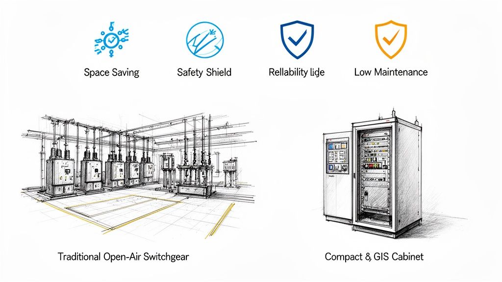
Historically, SF6 has dominated the high-voltage and extra-high-voltage world, where its exceptional dielectric strength allows for incredibly compact gas-insulated switchgear (GIS). You can learn more in our complete overview of how gas-insulated switchgear works. However, vacuum technology isn't standing still. Advances are constantly pushing VCBs into higher voltage classes, chipping away at SF6’s old territory.
For most industrial medium-voltage systems, the performance of a modern vacuum circuit breaker is more than enough to handle the job, making its environmental and maintenance advantages the real deciding factors.
Essential VCB Maintenance and Testing Procedures
It’s a common myth in the plant: the vacuum circuit breaker is so reliable you can just set it and forget it. While VCBs are incredibly low-maintenance compared to their older cousins, they are absolutely not zero-maintenance. If you want your VCB to hit its full 20 to 30-year lifespan without a hitch, you need a proactive, scheduled maintenance program.
Think of it like the engine in a heavy-duty truck. You wouldn’t dream of running it for years without an oil change or inspection, and the same logic applies here. For a VCB, this means a smart mix of visual checks, mechanical servicing, and a few critical electrical tests to get a real look under the hood.
Foundational Inspection and Mechanical Tasks
Most of the hands-on work for a VCB happens outside the sealed vacuum interrupter. You’re really focusing on the mechanical systems that do the physical work of opening and closing the breaker. Keeping them in prime condition is job one.
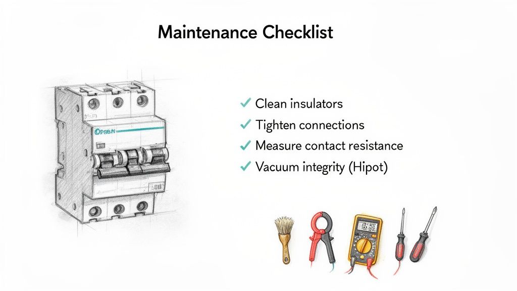
A solid annual inspection should always hit these points:
Cleaning Insulators: Over time, dust and grime can build up on the insulators. Add a little moisture, and you've created a perfect path for current to track to the ground. A simple wipe-down with an approved solvent is all it takes to prevent a flashover.
Checking Connections: Heat cycles make things expand and contract, and this can slowly loosen bolted electrical connections. A loose connection is a high-resistance hot spot waiting to happen. Technicians need to put a torque wrench on every primary and control connection to be sure.
Lubricating Linkages: The operating mechanism is a collection of pivots, rollers, and latches that need to move without a hint of resistance. A dab of the right lubricant ensures the breaker trips smoothly and instantly when it’s called on.
Key Diagnostic Electrical Tests
Mechanical checks are great, but the only way to know what's really going on inside is through electrical testing. These tests give you hard data on the health of the breaker’s most critical components.
A proactive testing schedule is non-negotiable. It turns maintenance from a reactive, break-fix headache into a predictive strategy that spots trouble long before it can shut you down.
There are three diagnostic tests that are absolute must-dos for any VCB:
Contact Resistance Measurement (CRM): Often called a "Ductor" test, this involves pushing a high DC current through the closed contacts and measuring the resistance in micro-ohms. If that number starts to creep up, it’s a huge red flag for problems like contact pitting or a failing connection that will overheat under load.
Insulation Resistance Test (Megger): Using a high-voltage DC source, this test checks the integrity of the breaker’s insulation. It’s fantastic at sniffing out contamination or moisture that could compromise the breaker’s ability to withstand system voltage. A low megohm reading tells you there's a problem that needs immediate attention.
Vacuum Integrity Test (Hipot): This is the moment of truth for the vacuum interrupter. You apply a high AC or DC voltage across the open contacts. A healthy vacuum is a near-perfect insulator and will hold the voltage easily. If the vacuum has been lost, the current will flash over, telling you the interrupter has failed and needs to be replaced.
Finally, don’t forget the simplest check of all: the contact wear indicator. This little mechanical gauge gives you a direct visual on how much life is left in the contacts. Keeping an eye on it lets you plan for the interrupter's replacement at the end of its life, ensuring your breaker is always ready to do its job.
How to Select the Right VCB for Your Application
Choosing the right vacuum circuit breaker isn't as simple as matching a few numbers on a spec sheet. It's a critical decision that hits right at the heart of your system's safety, reliability, and long-term performance. Think of it like picking an engine: you wouldn't put a sports car engine in a heavy-duty truck just because the horsepower looks good on paper. You have to consider the terrain and the job it needs to do.
To get it right, you need to look past the basic ratings and really dig into the specific demands of your application. A VCB tucked away in a clean, climate-controlled switchgear room faces a completely different set of challenges than one sitting in an outdoor substation, exposed to the elements year-round.
Analyzing Application-Specific Factors
The environment a VCB lives in plays a massive role in its performance and how long it will last. You have to account for all the ambient conditions that can put stress on its mechanical and electrical components.
Here are a few key environmental factors to nail down:
Installation Location: Is this breaker going indoors or outdoors? Outdoor models need much more robust, weatherproof enclosures and insulation systems built to handle everything from driving rain and snow to constant UV exposure.
Altitude and Humidity: Air gets thinner at high altitudes, which reduces its ability to insulate. For installations well above sea level, you’ll likely need a VCB with a higher insulation rating (BIL) to compensate. High humidity is another enemy, as it can cause condensation and lead to insulation breakdown if not managed.
Corrosive Atmospheres: If you're in a chemical plant, a paper mill, or a coastal area with salt spray, corrosion can eat away at enclosures and mechanical parts. In these spots, it's smart to specify upgraded materials like stainless steel or special protective coatings.
Matching the Breaker to the Load
Not all electrical loads are the same. The kind of equipment your VCB is protecting dramatically changes the type of stress it will see during switching. A breaker on a transformer feeder has a very different life than one switching a massive motor on and off.
The single most important step in selection is performing a system study to figure out the available fault current. This number dictates the breaker's required interrupting capacity. Undersizing this rating is a recipe for disaster—the VCB simply won't be able to extinguish a powerful short circuit.
Think about these common load types:
Motor Loads: Kicking on a large motor creates a huge inrush of current. The VCB has to be built to handle these repeated high-current events without breaking a sweat.
Capacitor Banks: Switching capacitor banks is known for generating high-frequency transient voltages that are incredibly tough on equipment. Breakers designed for this duty have special features to handle that stress.
Frequent Switching: Some applications, like arc furnaces, demand thousands of operations every single year. For that kind of duty, a VCB with a high mechanical endurance rating—say, 30,000 operations—is an absolute must.
This focus on detail is why the VCB market is booming. It recently hit USD 5.80 billion and is on track to reach USD 10.57 billion by 2034, all thanks to grid modernization projects and the demand for reliable, low-maintenance gear.
Ultimately, the goal is to build a detailed specification that you can use as a procurement checklist. By thinking through the operating environment, the load type, and the fault duty, you can be confident that the VCB you choose is a perfect match for your system. For specific models that meet these tough industrial requirements, you can learn more about options from the ABB circuit breaker line.
Got Questions About VCBs? We’ve Got Answers.
Even after you get the hang of vacuum circuit breakers, a few practical questions always pop up when it's time to put them to work. It’s one thing to know the theory, but another to confidently manage these critical assets in the field.
Let’s tackle some of the most common questions our engineers hear. Getting these real-world concerns sorted out is the key to making sure your electrical infrastructure is as safe and reliable as it can possibly be.
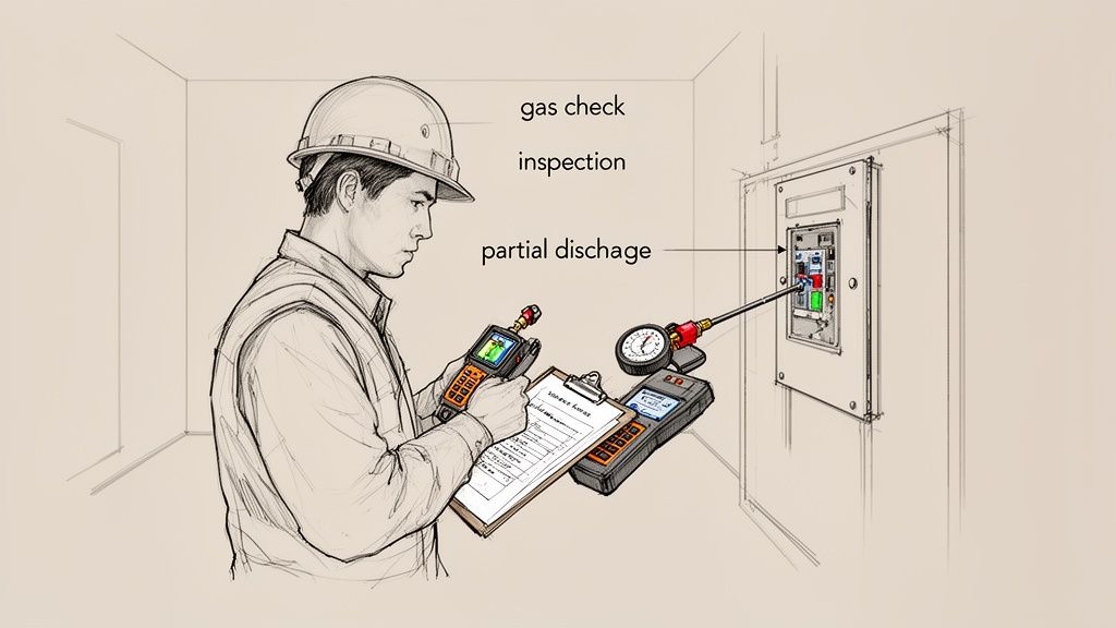
How Can You Tell If a Vacuum Interrupter Is Failing?
This is a tricky one because a failing vacuum interrupter looks exactly like a healthy one from the outside. There are absolutely no visual cues, which is why periodic electrical testing is so critical.
The gold standard for checking the internal integrity is a DC high-potential (Hipot) test. When you apply a specific test voltage across the open contacts, a healthy interrupter will hold it without any issue, proving the vacuum is solid. If current flashes over, that’s a dead giveaway—the vacuum is gone, and the interrupter needs to be replaced, pronto.
Another thing to keep an eye on is the built-in contact wear indicator. It’s a simple mechanical guide that gives you a visual heads-up when the internal contacts have eroded past their usable life after thousands of operations.
What Is the Typical Lifespan of a Vacuum Circuit Breaker?
You have to look at two things: its mechanical life and its electrical life. Mechanically, a modern VCB is a beast, built to handle anywhere from 10,000 to 30,000 open-close cycles. That means the mechanism itself is set for a long, long time.
The electrical life is a bit different; it really depends on how many faults it has to clear and how severe they are. That said, the sealed vacuum interrupter at its heart is designed for a service life of 20 to 30 years under normal conditions. In the end, how long your VCB actually lasts comes down to the environment it lives in and whether you stick to a proper maintenance schedule.
The real beauty of a vacuum circuit breaker's design is its longevity. With minimal contact erosion and a sealed, zero-maintenance interrupter, it delivers a predictable and extended service life that older technologies just can't touch.
Are VCBs Good for Frequent Switching Applications?
Absolutely. In fact, they’re the best choice for jobs that demand constant switching—think arc furnaces, heavy-duty motor starting circuits, or capacitor bank switching.
Here’s why: the arc is contained and snuffed out so quickly and cleanly inside the vacuum that the contacts barely wear down with each operation. This incredible mechanical endurance, combined with their ability to regain dielectric strength almost instantly, makes them the go-to for these high-demand scenarios. They handle the stress beautifully, reducing the wear and tear on both the breaker and your system over thousands of cycles where other breaker types would quickly burn out.
At E & I Sales, we live and breathe this stuff. We specialize in sourcing the right VCBs and building integrated solutions for the toughest industrial jobs out there. Our experts are here to help you specify, procure, and commission the perfect equipment to guarantee your facility’s safety and uptime.
Ever tried to squeeze a massive, sprawling electrical substation into a space the size of a large room? It sounds impossible, but that's precisely the problem gas insulated switchgear (GIS) was designed to solve. This technology takes all the critical, high-voltage equipment—circuit breakers, switches, busbars—and seals them inside a compact, metal-enclosed housing filled with an insulating gas.
The result is a dramatic reduction in physical footprint, turning a land-intensive engineering challenge into a manageable one.
What Is Gas Insulated Switchgear and How It Works
Think about the difference between a classic, air-cooled engine with all its exposed parts and a modern, liquid-cooled system. The liquid coolant is a much more efficient medium, allowing the entire engine to be smaller, more powerful, and more reliable.
Gas insulated switchgear applies this same core principle to high-voltage power equipment. Instead of relying on open air to insulate components—which demands huge safety clearances to prevent electrical arcs—GIS uses a specialized gas that is far more effective.
This simple shift in approach lets engineers shrink the switchgear's footprint by up to 90% compared to conventional air-insulated switchgear (AIS). For projects in dense urban centers or crowded industrial plants where every square foot counts, this is a total game-changer.
The Power of Compact Design
The magic behind GIS is its exceptional dielectric strength—the insulating gas's ability to handle immense electrical stress without breaking down. The industry standard, Sulfur Hexafluoride (SF6), is several times more effective at insulating than plain air. This means high-voltage conductors and components can be safely placed just inches apart, rather than many feet.
This incredibly compact, modular design delivers a few powerful advantages:
Massive Space Savings: GIS can be installed indoors, underground, or tucked away in tight industrial spaces where a traditional AIS substation simply wouldn't fit.
Unmatched Reliability: The sealed, controlled environment protects all the internal components from the outside world. Dust, moisture, salt spray, and other contaminants can't get in, leading to a much longer service life and fewer outages.
Superior Safety: With all live parts completely enclosed and grounded, the risk of accidental contact for personnel is virtually eliminated.
The market's growth tells the story. Valued at USD 22 billion in 2022, the global gas insulated switchgear market is on track to hit an incredible USD 55.8 billion by 2034. As cities expand and industries modernize, the demand for efficient, space-saving power infrastructure is only going up. You can dig deeper into these market trends for gas insulated switchgear over at gminsights.com.
The choice between GIS and AIS is a fundamental one that reshapes the entire approach to a project. It transforms a major land-use problem into a straightforward architectural one, opening up new possibilities for development in constrained areas.
GIS technology is a cornerstone of modern electrical substation design, allowing more power to be delivered more reliably in less space. From data centers and manufacturing plants to urban high-rises, GIS provides a tough, dependable solution where both performance and footprint are non-negotiable.
GIS vs AIS At a Glance
To put it all in perspective, here's a quick comparison of the two technologies. While both serve the same fundamental purpose of controlling and protecting electrical circuits, their design philosophies are worlds apart.
Ultimately, GIS represents a more advanced, contained, and robust approach to switchgear, trading a higher upfront cost for long-term reliability, safety, and a much smaller physical presence.
Understanding What’s Inside a GIS System
To really get what makes gas-insulated switchgear so different, you have to look inside that sealed, metal enclosure. It’s not just a box; it's a precisely engineered ecosystem where every component works together to control and protect high-voltage circuits. Think of it as a specialized crew operating in a perfectly controlled environment.
Each part is designed for maximum performance and a long service life, all contained within a single housing filled with an insulating gas. This fundamental design is the secret behind GIS's compact size, incredible reliability, and enhanced safety.
The image below sums up how these core principles translate into real-world benefits.
As you can see, the superior insulation is the key—it enables everything else, from the smaller footprint to rock-solid reliability. Now, let’s unpack the components that make it all happen.
The Protective Core: Circuit Breaker and Switches
The circuit breaker sits at the very heart of the switchgear. It's the system's first line of defense, designed to slam the door on electricity flow in milliseconds when it detects a fault like a short circuit. Inside a GIS, this all happens within the insulating gas, which is exceptionally good at extinguishing the massive electric arc that forms when a high-voltage circuit is broken.
But the breaker doesn't work alone. Two other switches are crucial for safe operation and maintenance:
Disconnectors (or Isolators): These create a clear, physical air gap in the circuit for total isolation. They’re only operated when the circuit is already de-energized, giving crews a visible guarantee that a piece of equipment is safely disconnected before they start work.
Earthing Switches (or Grounding Switches): Once a section is isolated by the disconnector, this switch connects the conductors directly to the ground. It’s a non-negotiable safety step that drains any residual charge and prevents induced voltage from becoming a hazard to personnel.
The Insulating Medium: The Secret Sauce
The real star of the show in a gas insulated switchgear system is the gas filling the enclosure. For many years, that gas was Sulfur Hexafluoride (SF6), a synthetic compound with incredible dielectric strength—basically, its ability to stop electricity from arcing where it shouldn't. To put it in perspective, SF6 is roughly 2.5 times more effective as an insulator than pure nitrogen and lightyears ahead of air.
The catch? SF6 is also a powerful greenhouse gas. With environmental regulations becoming stricter, the industry is quickly moving toward SF6-free alternatives. These "green" gases, like fluoronitrile-based mixtures or even highly pressurized clean air, offer similar insulating performance with a much, much smaller environmental footprint.
The insulating gas is the game-changer that allows for such a dramatic size reduction. By preventing arcs between live parts, it removes the need for the wide, open-air gaps you see in conventional switchgear. This lets engineers pack everything closer together, making the whole assembly smaller and far more robust.
The Monitoring and Measurement Tools
You can't control what you can't measure. That’s where instrument transformers come in—they are the eyes and ears of the GIS, constantly monitoring the system's vital signs.
You'll always find two main types:
Current Transformers (CTs): These devices safely measure the massive currents flowing through the conductors. They "step down" the current to a low, manageable level that can be read by protective relays and meters without vaporizing them.
Voltage Transformers (VTs): In the same way, VTs measure the extremely high system voltage, reducing it to a standardized, low value that monitoring and protection equipment can safely handle.
When you put it all together—the breakers, the switches, the gas, and the transformers—you get a completely self-contained and highly integrated system. Every single part is optimized to function perfectly within that controlled gas environment, achieving a level of performance and reliability that's tough for traditional, air-insulated gear to match. This tight integration is what makes gas-insulated switchgear the go-to choice for so many critical applications.
Why GIS Is a Smarter Choice for Industrial Operations
Picking the right switchgear isn't just a technical detail—it's a strategic decision that ripples through your entire operation, impacting efficiency, safety, and your bottom line. For any industrial facility, gas-insulated switchgear (GIS) makes a compelling business case by turning its sophisticated design into real-world, tangible benefits. This is about more than just managing power; it’s about optimizing your whole operational environment.
Let’s dig into the four key advantages that make GIS the go-to choice for plant engineers, project managers, and operations leaders who expect more from their critical infrastructure.
Free Up Your Most Valuable Asset: Space
In any industrial plant, floor space is gold. Every square foot tied up by non-production equipment is a missed opportunity for revenue-generating machinery or a more efficient workflow. This is where the compact nature of gas-insulated switchgear delivers its most immediate and striking advantage.
Because all its key components are sealed inside a gas-filled tank, a GIS unit can be up to 90% smaller than its air-insulated cousins.
This isn't just a minor perk; it's a strategic game-changer. It can be the deciding factor that allows a facility expansion to move forward instead of stalling due to site constraints. For a packed manufacturing floor, it could free up enough room for an entire new production line, directly boosting output and profitability.
Elevate Plant and Personnel Safety
Safety is absolutely non-negotiable in an industrial setting, and GIS is fundamentally built for it. Traditional air-insulated switchgear often has exposed live conductors, which poses a constant risk of accidental contact for any personnel working nearby.
With GIS, every live component is completely contained within a grounded metal enclosure. This design all but eliminates the risk of electric shock, making it an inherently safer technology for environments where people are working in close proximity to high-voltage equipment.
The sealed-for-life design of gas-insulated switchgear creates a controlled internal environment that is immune to external factors. This not only enhances reliability but also creates a formidable barrier between high-voltage electricity and the people who work around it every day.
This built-in safety shield reduces the chance of accidents and simplifies critical lockout-tagout procedures, leading to a more secure and efficient workplace. It also means the equipment is protected from accidental bumps from forklifts or other machinery, further protecting your operations.
Achieve Superior System Reliability
Industrial processes live and die by a constant, uninterrupted flow of power. Unplanned downtime can rack up thousands of dollars in losses every single minute, which puts equipment reliability at the very top of the priority list.
The sealed design of gas-insulated switchgear is its greatest strength. It essentially creates a fortress, shielding all critical internal parts from the harsh realities of an industrial plant.
Immunity to Contaminants: Dust, moisture, corrosive chemicals, and other particles common in industrial settings simply can't get inside to degrade the components.
Stable Performance: The controlled gas atmosphere provides consistent insulating performance, no matter what the external humidity or altitude is doing—factors that can easily affect air-insulated gear.
Fewer Outage Risks: This protection dramatically cuts down the risk of flashovers and faults caused by environmental contamination, giving you significantly higher uptime for your most critical processes.
Minimize Maintenance and Lower Lifecycle Costs
While the initial price tag for GIS can be higher, its long-term economic advantages are undeniable. The equipment is engineered for a service life of 30 to 40 years with very little intervention needed. Since the internal parts aren't exposed to environmental wear and tear, the need for routine cleaning and inspection is drastically reduced.
This all translates to fewer planned shutdowns, lower labor costs for maintenance, and a much smaller spare parts inventory to manage. When you look at the total cost over the equipment's entire lifecycle, these savings in operational expenses often make gas-insulated switchgear the more cost-effective solution. This superior technical design is precisely why GIS is a cornerstone of modern power infrastructure. You can find more insights on the global GIS market over at techsciresearch.com.
While GIS is a powerhouse for high-voltage distribution, it often works alongside other key equipment. To see how it fits into the bigger picture, check out our guide comparing motor control centers vs. switchgear.
How to Specify and Procure the Right GIS Solution
Picking the right gas-insulated switchgear isn't just a purchase; it's a major investment in your electrical system's future. To get it right, you have to look beyond the basic voltage rating and dig into a detailed specification process. It’s all about balancing technical muscle, lifecycle costs, and what the future might throw at you.
Let’s walk through a framework that helps engineers and procurement managers make a truly informed decision, not just a quick one.
Defining Your Technical Specifications
The first step is getting crystal clear on your core electrical and physical needs. This is about more than just the system voltage—it's about deeply understanding the real-world demands the GIS will face every day and during a worst-case scenario fault.
Think of your technical spec sheet as the blueprint for the entire project. If it's vague, you're inviting mismatched quotes and costly delays. You need to nail down every critical parameter.
Key electrical numbers you absolutely must define include:
Rated Voltage and Frequency: The fundamentals, like 145 kV at 60 Hz.
Rated Continuous Current: The absolute maximum current the main components can handle non-stop without breaking a sweat.
Short-Circuit Withstand Current: The gut-punch of a fault current the GIS has to survive without damage for a specific time, usually 1 or 3 seconds.
Basic Insulation Level (BIL): This proves the gear can handle massive voltage surges from things like lightning strikes or other switching events on the grid.
But don't stop there. You have to consider the physical world your GIS will live in. Is it going into a brand-new concrete building, a compact e-house, or being squeezed into a tight basement? Get the tape measure out. Document the exact footprint available, paying close attention to height limits and access routes needed for both installation and future maintenance.
Evaluating the Insulation Medium
For decades, SF6 gas was the undisputed king of insulation. But the world is changing. Environmental regulations are getting tighter, and that's pushing SF6-free alternatives from a "nice-to-have" to a "must-consider."
The EU, for instance, is already moving to phase out SF6 in new switchgear, with the first major deadline hitting in 2026 for medium-voltage equipment. That’s a clear signal of where the entire industry is headed.
When you're talking to potential suppliers, press them on the gas issue:
SF6-Free Options: Do they have field-proven alternatives? Are they using modern gas mixtures based on fluoronitriles or even just clean air? Ask for case studies and operational history.
Global Warming Potential (GWP): Get the numbers. Compare the GWP of their proposed alternative directly against SF6. Today's best options can slash GWP by over 99%.
Gas Handling: What’s the real story on handling and recycling the new gas? What special equipment or training is needed for installation and eventual decommissioning?
Opting for an SF6-free solution today is a smart move. It effectively de-risks your investment against future carbon taxes or outright bans, protecting your asset for the long haul.
GIS Specification Checklist
To make sure you cover all your bases, a detailed checklist is your best friend. It transforms your requirements from a simple list into a robust specification that suppliers can quote against accurately. Here’s a practical template to get you started.
Parameter
Key Considerations
Example Specification
Voltage & Current
System voltage, frequency, continuous current needs, and short-circuit withstand for 1s or 3s.
Rated Voltage: 145 kV; Rated Current: 2500 A; Short-Circuit: 40 kA for 3s.
Insulation Level (BIL)
Must withstand lightning and switching surges common to your grid environment.
Lightning Impulse (BIL): 650 kVp.
Insulating Medium
Is SF6 acceptable, or is an SF6-free alternative required? Consider GWP, handling procedures, and long-term viability.
Gas mixture with GWP < 1. Supplier to provide gas handling and lifecycle plan.
Footprint & Layout
Maximum allowable dimensions (L x W x H). Access requirements for installation and maintenance. Indoor or outdoor placement?
Indoor installation; Max footprint: 15m x 5m x 4m (L x W x H).
Configuration
Single busbar, double busbar? Number of incoming and outgoing feeder bays required.
Single busbar configuration; 2x Incoming Lines, 4x Transformer Feeders.
Maintenance Philosophy
Define expected maintenance intervals. Are sealed-for-life components a priority?
Minimal maintenance required; major inspection interval > 20 years.
Ambient Conditions
Operating temperature range, altitude, and seismic requirements for the installation site.
Temperature: -5°C to +40°C; Altitude: < 1000m; Seismic Zone 3 compliant.
Standards & Testing
Specify compliance with IEC or ANSI/IEEE standards. Mandate a full Factory Acceptance Test (FAT).
Compliance with IEC 62271-203. FAT to be witnessed by owner's engineer.
Using a structured checklist like this ensures nothing falls through the cracks and you get a GIS that’s perfectly suited for the job.
Looking Beyond the Price Tag to Total Cost
One of the biggest mistakes you can make is choosing a GIS based on the initial price tag alone. You have to think bigger. A true evaluation looks at the Total Cost of Ownership (TCO), and this is where GIS often shines, even if the upfront cost is higher.
Why? The incredibly compact footprint.
The decision to use GIS can reduce land acquisition or building construction costs so drastically that it more than offsets the higher equipment price. For urban projects or plant expansions, this factor alone can make GIS the most economically viable choice.
When you run the numbers for TCO, be sure to include:
Land and Civil Works: The smaller footprint means a smaller bill for real estate and construction. It’s that simple.
Installation and Commissioning: GIS modules are typically assembled and tested in the factory, which dramatically cuts down on the time and complexity of on-site work.
Maintenance Costs: The sealed-for-life design means far less maintenance. That translates to lower labor costs and less planned downtime over a 30-40 year service life.
Ensuring Compliance and Quality
Finally, you need to be uncompromising on quality assurance. Your GIS is a linchpin of your electrical system, and its reliability hinges on strict adherence to international standards and rigorous testing. Don't be shy about making demands.
Before you sign any contract, get clear, written answers to these questions:
Standards Compliance: Does the equipment fully comply with the relevant IEC or ANSI/IEEE standards for design, manufacturing, and testing? Ask for the specific standard numbers.
Factory Acceptance Testing (FAT): A comprehensive FAT is non-negotiable. It's your chance to verify the equipment performs as promised before it ever leaves the factory. To get a better handle on this, check out our guide on what a factory acceptance test checklist should cover.
Commissioning Support: What level of hands-on support will the supplier provide on-site? This includes installation supervision, gas filling, and the final commissioning tests to bring the system online.
By following this structured path—nailing down your technical needs, weighing the new gas alternatives, analyzing the total cost, and demanding tough quality checks—you can confidently choose a GIS that will deliver safety, reliability, and value for decades to come.
Getting GIS Installation and Maintenance Right
A gas-insulated switchgear system is built to last, often designed for a service life of 30 to 40 years. But getting there isn't a given. That kind of longevity depends entirely on a flawless installation and a smart, forward-thinking maintenance plan. This is the stage where your investment’s long-term reliability is truly locked in.
The initial setup is, without a doubt, the most critical phase in a GIS's entire life. Unlike its air-insulated cousins that are more forgiving, a GIS demands precision and a controlled environment. Any shortcut or mistake made here can plant a hidden problem that might not show itself for years.
Executing a Flawless GIS Installation
Putting together a GIS is less like construction and more like performing surgery. The whole point is to assemble the factory-built modules while keeping the insides completely pristine—free of any contaminants that could weaken the insulating gas.
A clean, dry, and controlled setting is non-negotiable. Dust, moisture, or even tiny metallic shavings can cripple the dielectric strength of the SF6 gas. That’s why the assembly is often done inside temporary clean rooms or under positive-pressure tents right on the construction site.
The integrity of a GIS is established the moment its compartments are sealed. A single foreign particle or a trace of moisture introduced during assembly can become a nucleation point for partial discharge, slowly degrading the insulation and leading to a potential failure down the road.
Beyond the environment, the people doing the work are just as crucial. Handling the gas—filling the compartments with SF6 or an alternative—is a job for certified technicians. They use specialized gear to make sure the gas is at the perfect density and purity, because even small deviations can throw off performance. This is the kind of precision that separates a world-class installation from a future headache.
Pre-Commissioning Tests: The Final Gatekeeper
Before a new GIS system ever sees a live current, it has to pass a tough battery of pre-commissioning tests. Think of these as the final quality check, proving that the on-site assembly went perfectly and the gear is ready to do its job.
Here are the must-pass checks:
High-Voltage Withstand Test: This is where we apply a high voltage for a specific time to make sure the insulation system is solid and that no hidden defects from shipping or assembly exist.
Gas Quality and Leak Checks: Technicians verify the purity and moisture content of the gas. They also run highly sensitive leak detection tests on every flange and joint to ensure the system is sealed tight, targeting leakage rates below 0.1% per year.
Operational Checks: Every moving part—circuit breakers, disconnectors, earthing switches—is operated multiple times. This confirms they all move smoothly and within the manufacturer's specified timings.
Long-Term Care: What "Maintenance-Free" Really Means
You’ll often hear GIS described as "maintenance-free," but that term can be a bit misleading. It doesn’t mean you can just install it and walk away. What it really means is that GIS requires far less invasive maintenance than air-insulated switchgear. The focus shifts from constant cleaning and parts replacement to smart, non-invasive monitoring.
Routine care for a GIS comes down to a few key activities. The most basic is keeping a close eye on the gas density. Modern systems have sensors that constantly track the temperature-compensated pressure, giving you an early warning if a leak develops.
Periodic visual inspections are also essential. A simple walk-through can catch a lot—signs of corrosion on the enclosure, checking that control circuits are in good shape, and making sure all monitoring gauges are working properly.
Advanced diagnostics are where modern GIS care really shines. Techniques like Partial Discharge (PD) monitoring can detect tiny electrical sparks inside the insulation, which are often the very first sign of a developing fault. Similarly, acoustic monitoring can pick up on unusual mechanical vibrations from moving components. This condition-based approach means you schedule work when it's actually needed, not just because the calendar says so, maximizing uptime and helping your GIS deliver reliable power for decades.
Common Questions About Gas Insulated Switchgear
As gas insulated switchgear starts showing up more and more in critical power systems, it’s only natural for engineers, project managers, and facility owners to have questions. This technology is a different beast compared to traditional switchgear, and getting a handle on the specifics is key to making the right call.
We’ve rounded up some of the most common questions we hear about GIS. The goal here is to give you clear, straightforward answers that cut through the jargon and build on what we've already covered.
What Is the Primary Difference Between GIS and AIS?
It all comes down to the insulating medium. Think of it like this: traditional Air Insulated Switchgear (AIS) uses the air in the room to keep high-voltage components from arcing over. Since air isn't a fantastic insulator, you need a lot of space—big physical gaps between conductors. This is why AIS lineups are so massive.
Gas Insulated Switchgear (GIS), on the other hand, puts all its live components inside a sealed, grounded metal enclosure filled with a special insulating gas. This gas is a powerhouse insulator, with a much higher dielectric strength than air. That lets you safely place components incredibly close together.
The result? A GIS assembly can be up to 90% smaller than its air-insulated equivalent. It’s a game-changer for tight spaces like urban substations, crowded industrial plants, or offshore platforms.
Are There Environmental Concerns with the SF6 Gas Used in GIS?
Yes, that’s a fair question and a big topic in the industry. The gas traditionally used, Sulfur Hexafluoride (SF6), is an extremely potent greenhouse gas. To put it in perspective, its global warming potential (GWP) is about 24,300 times higher than carbon dioxide.
But it’s important to see the whole picture. Modern GIS units are built as sealed-for-life systems. They come with factory-guaranteed leakage rates that are incredibly low—typically less than 0.1% per year. The industry is also heavily regulated on how to handle, recycle, and dispose of SF6 to keep it out of the atmosphere.
The real story, though, is the rapid shift toward SF6-free alternatives. These "green" gases deliver the same great insulating performance but slash the global warming potential by over 99%. This move essentially neutralizes the long-term environmental footprint for new GIS installations.
This isn't just a voluntary trend; it's becoming law. The EU, for instance, is set to phase out SF6 in most new medium-voltage switchgear as early as 2026.
Is GIS More Expensive Than Traditional Switchgear?
If you only look at the initial price tag, yes, GIS equipment usually has a higher upfront cost than comparable AIS. But that's a very narrow way to look at it. A smart financial analysis always considers the total cost of ownership (TCO).
Over its lifespan, GIS often works out to be the more economical choice. The massive reduction in footprint alone can save a fortune in land or building costs, especially in pricey urban areas where every square foot counts.
On top of that, GIS is practically maintenance-free. With all the critical parts sealed away from dust, moisture, and corrosive air, you get some major long-term benefits:
Lower operational and labor costs
Far less planned downtime for cleaning and upkeep
A longer, more reliable service life, often 30-40 years
When you run the numbers on all these factors, the GIS investment looks much more attractive and frequently beats the lower sticker price of AIS in the long run.
What Are the Typical Applications for Gas Insulated Switchgear?
GIS is incredibly versatile, but it really shines in places where space is tight, reliability is an absolute must, or the environment is just plain nasty.
Its tough, compact design makes it the go-to solution for a huge range of critical infrastructure.
You’ll find it in:
Urban Power Substations: Perfect for tucking into buildings or even underground where real estate is scarce.
Power Generation Plants: Including wind and solar farms where a small, reliable footprint is essential.
Heavy Industrial Facilities: Think manufacturing plants, oil and gas rigs, and mines where dust, chemicals, and moisture would destroy conventional gear.
Data Centers: Where an uninterruptible power supply is the lifeblood of the business.
Transportation Infrastructure: Used extensively in railway systems and airports that can't afford downtime.
The plug-and-play, modular nature of GIS also makes it ideal for prefabricated e-houses and mobile substations that need to be deployed and energized fast.
Navigating the complexities of modern electrical systems requires a partner with deep expertise. At E & I Sales, we specialize in designing and integrating reliable power distribution and motor control solutions, from MV switchgear to custom UL control panels. If you're planning a project that demands performance and efficiency, our team has the field experience to deliver a solution that meets your exact specifications.
Picture this: your big plant expansion project is dead in the water. Why? Because the new VFDs from one vendor refuse to talk to the PLCs from another. It's not just a technical snag; it's a full-blown operational crisis, leading to downtime, safety concerns, and a budget that's spiraling out of control.
If that sounds familiar, you already know the truth: systems integration isn't just an IT problem, it's a core business strategy.
Why Strategic Systems Integration Is a Game-Changer
When done right, professional systems integration services take all those disparate pieces of equipment—motor controls, automation hardware, power distribution gear—and make them work together as a single, well-oiled machine. Too many project managers treat integration as an afterthought, something to bolt on at the end. That’s a mistake. The smart ones know it's the foundation of operational excellence. It’s what separates a random collection of machines from a truly unified production line.
This guide isn't about textbook definitions. It’s a practical roadmap for using integration to turn that potential chaos into a real competitive advantage. My goal here is to give you, the engineer or buyer on the ground, the tools you need to specify, select, and manage these critical services effectively.
The Business Case for Getting It Right
In an industrial plant, integration failures hit the bottom line—hard and fast. When a new variable frequency drive (VFD) can't communicate with the central PLC, or a motor control center (MCC) isn't properly tied into the SCADA system, the whole process can just stop. These aren't minor bugs; they're fundamental breakdowns.
This is where a good systems integrator proves their worth, delivering tangible results that you can see in your P&L. The real benefits are clear:
Slash Operational Downtime: Systems built to work together are just more reliable. A unified control architecture means you can find and fix problems faster, getting equipment back online in minutes, not hours.
See Everything, Control Everything: When all your components are speaking the same language, you finally get a complete picture of your operation. This is gold for making smarter decisions, implementing predictive maintenance, and optimizing your processes.
Boost Safety and Compliance: A qualified integrator is your best defense against non-compliance. They ensure every part of the system, like UL 508A for control panels, meets the right standards and that safety circuits are rock-solid.
Build for the Future: A smart integration plan always looks ahead. A well-designed system makes it far easier to add capacity or upgrade technology later without having to rip everything out and start over.
People often think integration is just about connecting a few wires. The reality is, it’s about creating a seamless flow of data and control that directly supports your business goals, whether that’s boosting throughput or cutting energy costs.
Bridging the Physical and Digital Worlds
Modern plants are a complex dance between physical machinery (motors, pumps, conveyors) and the digital brains that run them. A systems integrator is the choreographer making sure that dance is perfectly synchronized.
This involves a lot more than just software. While many resources talk about connecting business apps—and for a deeper dive on that, you can check out this overview of software integration services—our world is different.
Here on the plant floor, the focus is on making heavy iron work together intelligently. In the sections that follow, I'll walk you through the nitty-gritty of managing these projects to make sure your investment pays off.
Defining Your Project Scope and Technical Needs
A vague project scope is the single biggest threat to your budget and timeline. I’ve seen it happen time and again—ambiguity leads to misunderstandings, costly change orders, and a lot of finger-pointing when things go sideways.
A successful project always starts with a crystal-clear Scope of Work (SOW). Think of this document as the definitive blueprint for everyone involved. It’s not just paperwork; it’s your first and best defense against scope creep.
When you hand a detailed SOW to potential systems integration services providers, you empower them to give you accurate, competitive bids. They can see exactly what you need, from hardware preferences to performance targets, which kills the guesswork. The result is a much smoother project, from design to commissioning, because you set clear expectations right from the start.
From Business Goals to Technical Specs
Your SOW has one primary job: translate high-level business objectives into concrete technical requirements an integrator can actually build from. It’s not enough to say you want a "more efficient system." You have to get specific and quantify what that means.
Start by defining your operational goals in measurable terms. Are you trying to boost production, cut down cycle times, or improve energy efficiency? A well-defined goal immediately gives the project direction.
For instance, a goal like "increase conveyor throughput by 15%" is infinitely more useful than just "make the conveyor faster." This specific target directly informs decisions about motor sizing, VFD programming, and PLC logic. These are the kinds of details any firm providing industrial controls and automation solutions needs to design the right system.
Make sure your SOW nails down these core elements to eliminate any confusion:
Operational Objectives: State the business or production goals clearly. Use numbers and metrics whenever you can.
Hardware and Software Specs: List any required or preferred manufacturers for PLCs, VFDs, HMIs, and other key components. If your plant has standardized on a particular platform, say it loud and clear.
Communication Protocols: Define the network architecture. Does the system need to communicate over EtherNet/IP, PROFINET, Modbus TCP, or something else?
Compliance and Standards: This is non-negotiable. List all required industry standards, like UL 508A for control panels, and include any of your own corporate safety or engineering standards.
Building a Comprehensive Scope of Work
A truly effective SOW leaves no room for interpretation. It’s a detailed document that covers every phase of the project, from the parts list to the final documentation you expect to receive. It's the ultimate checklist to ensure you get exactly what you paid for.
A strong SOW isn't about micromanaging your integrator. It’s about creating a shared understanding of success. When both parties know exactly what the finish line looks like, you’re far more likely to get there on time and on budget.
The table below breaks down the key components every industrial integration SOW should have. Use this as a guide to make sure you've covered all your bases before sending the project out for bid. This level of detail helps potential partners understand the full picture, which leads to better questions and more accurate proposals.
Key Components for a Systems Integration SOW
Use this checklist to ensure your Scope of Work is comprehensive, clear, and provides all the necessary details for accurate integrator bidding.
Component
What to Include
Practical Example
Project Overview
A high-level summary of the project's purpose and the problem it solves.
"Upgrade the main packaging line's control system to increase throughput by 15% and replace obsolete PLC hardware."
Mechanical Scope
Details on physical equipment being controlled or installed.
"Integrator to provide controls for a new conveyor system (Model XYZ). All mechanical installation by others."
Electrical Scope
Power requirements, source of power, and panel specifications.
"The new control panel will be fed from MCC-04, breaker 22. Panel must be UL 508A certified and include a main disconnect."
Control Narrative
A detailed, step-by-step description of how the system should operate.
"When the start button is pressed, the conveyor motor will ramp up to 60 Hz over 5 seconds. A photo-eye will count boxes."
Deliverables
A list of all documentation to be provided upon completion.
"As-built electrical drawings in AutoCAD format, PLC and HMI source code, a complete Bill of Materials, and O&M manuals."
Putting in the time to create a thorough SOW upfront is one of the best investments you can make. It sets the stage for a successful partnership and ensures the systems integration services you receive are perfectly aligned with your operational needs, preventing costly surprises down the road.
How to Select the Right Integration Partner
Choosing a partner for your systems integration services based on the lowest bid is one of the oldest, and most expensive, mistakes in the book. It’s a classic trap. That low initial quote often balloons with change orders, unexpected downtime, and non-existent support when you need it most.
The real goal isn't to find the cheapest contractor. It’s to find a true partner who delivers long-term value and reliability you can count on.
This means you need a solid evaluation process that goes way beyond the price tag. You’ve got to dig into a potential partner’s technical chops, their real-world industry experience, how they manage projects, and their safety culture. A slick proposal is one thing; proven execution is what actually matters.
Beyond the Bid Price: Technical Expertise
Your first filter should always be technical competence. It's non-negotiable. Does the integrator have deep, hands-on experience with the specific hardware and software platforms humming away in your facility? This is absolutely critical for core components like PLCs and VFDs.
When an integrator is a certified partner with brands like Rockwell Automation or Siemens, it's more than just a piece of paper. It means they have a direct line to technical support, specialized training, and product roadmaps that a generalist simply can't access. That inside track can be a lifesaver when you're troubleshooting a complex issue during commissioning.
When you're vetting potential partners, ask specific, probing questions about their experience:
Platform Proficiency: Get them to talk about recent projects using the exact PLC family you plan to use (e.g., ControlLogix, S7-1500).
Network Knowledge: How much experience do they have with the industrial protocols in your scope, like EtherNet/IP or PROFINET? Ask how they guarantee network reliability.
In-House Capabilities: Find out what work they do themselves versus what they subcontract. Do they have an in-house UL 508A panel shop? Keeping programming and engineering in-house almost always leads to better quality control and a more cohesive final product.
The real value of a top-tier integration partner isn't just their ability to follow a scope of work. It's their capacity to spot potential problems you haven't thought of and recommend better, more reliable solutions based on their deep product knowledge.
Evaluating Industry Experience and Past Performance
General automation experience is good. But direct experience in your industry is a whole lot better.
An integrator who understands the unique headaches of a food and beverage plant—like clean-in-place requirements and traceability—will deliver a far better result than one who has only ever worked in automotive manufacturing. Relevant experience means they already speak your language and won't be learning on your dime.
Checking references is a step you cannot skip. And don't just ask for a list of happy clients. Ask specifically for contacts from projects that were similar in scope and complexity to yours.
When you call those references, ask the tough questions:
How did the integrator handle unexpected curveballs or scope changes?
Was the project documentation—drawings, code, manuals—thorough and accurate?
Would you hire them again for another critical project? The answer to that last one tells you everything you need to know.
A site visit can also be incredibly revealing. Ask to tour their facility, and more importantly, their panel shop. A clean, organized shop with clear quality control processes is a huge indicator of a disciplined, professional organization. A messy, chaotic shop is a major red flag. If you want to dive deeper, you can learn more about the key characteristics of an effective industrial automation system integrator on our blog.
The Value-Based Decision
Ultimately, your decision has to come down to value, not just cost. A slightly more expensive partner with deep expertise, a proven track record, and robust support systems will almost always deliver a lower total cost of ownership. Their systems are simply more reliable, easier to maintain, and are backed by a team you can count on.
Create a simple evaluation matrix to score potential partners objectively across your key criteria. This is a great way to move the conversation away from a single price point and toward a more balanced, value-focused decision.
Your future self will thank you when the system is running flawlessly years from now.
Managing the Project from Kickoff to Commissioning
You’ve signed the contract and selected your integration partner. Great. Now the real work starts.
Signing that dotted line isn't the finish line; it’s the starting gun. If you want this project to land on time and on budget, you have to stay actively engaged. A hands-off approach is a recipe for missed deadlines, scope creep, and a final product that doesn’t quite hit the mark.
Think of yourself as the project's co-builder. Your integrator handles the technical heavy lifting, but your job is to provide clear direction, fast feedback, and firm approvals. We can break this entire process down into a few key phases, each with its own critical milestones.
Setting the Stage with a Strong Kickoff
The project kickoff meeting is more than just a formality—it’s your first and best chance to set the tone for the entire engagement. This is where you get both teams in a room and translate that written Scope of Work into a shared game plan.
During this meeting, you need to lock down a few non-negotiable processes. Getting these things right from day one will save you a world of headaches later.
Establish a Single Point of Contact: Designate one person on your team and one on the integrator’s to be the official communication channel. This prevents crucial information from getting lost in a flurry of emails between different engineers and managers.
Nail Down the Change Order Process: Let's be realistic—scope creep happens. But it doesn't have to create chaos. Define a formal, written process for how any changes are requested, quoted, approved, and tracked. No "oh, by the way" additions.
Confirm the Project Schedule: Go through the timeline milestone by milestone. Pay special attention to the critical path and identify anything that depends on your team, like getting the integrator access to the facility or digging up old electrical drawings.
The Design and Submittal Phase
With the ground rules set, the integrator’s engineering team gets to work turning your operational needs into detailed electrical designs. This stage ends with the delivery of the design submittal package. This is a huge milestone. Your sign-off here gives them the green light to start ordering parts and building panels.
This package is your first tangible look at the system. It’ll include things like electrical schematics, panel layout drawings, and a detailed Bill of Materials (BOM). Don't just skim it. Scrutinize every single page. A change on paper costs next to nothing. A change after a control panel has been wired can cost thousands and delay the project for weeks.
Treat the design submittal like the final blueprint for a house. Once you sign off, you’re saying, "Yes, this is what I want you to build." You are confirming that the design will meet your operational and technical needs.
The Power of Factory Acceptance Testing
Before a single piece of equipment ships to your site, it needs to be put through its paces at the integrator's shop. This is called the Factory Acceptance Test (FAT), and it is arguably the single most important risk-mitigation step in the entire project.
The FAT is your chance to see the system run in a controlled environment. You can find software bugs, test the HMI screens, and request changes before that panel ever leaves their facility. A well-run FAT can catch and fix up to 90% of potential issues before they have a chance to cause massive delays during on-site commissioning.
You should see the panel fully powered up, connected to simulators that mimic your real-world devices. You'll get to watch the PLC logic execute and make sure the operator interface is intuitive. To make sure you cover all your bases, a solid checklist is a must. You can use our Factory Acceptance Test checklist as a starting point to build your own.
From Installation to Final Acceptance
Once the FAT is successfully in the rearview mirror, the system is shipped to your facility for installation. The integrator will handle the physical work of mounting panels and pulling wires, but your role is to clear the path for them. That means coordinating with other trades, ensuring site access, and making sure everyone follows your plant’s safety rules.
After the hardware is in place, the Site Acceptance Test (SAT) begins. This is the moment of truth. While the FAT tested the system in isolation, the SAT proves it works with your actual machinery. It's the final validation that the integrator has delivered on their promises, leading to the final project sign-off and official handover.
Mitigating Common Risks and Measuring True ROI
Let's be realistic: every industrial project has potential landmines. Even with the best planning, things can go sideways. While bringing in professional systems integration services is a huge step in the right direction, you can't just set it and forget it. You need to be aware of the common pitfalls to manage them proactively instead of just reacting when things catch fire.
Two of the biggest project-killers I see time and again are scope creep and interoperability failures.
Scope creep is that slow, insidious addition of "just one more thing" that wasn't in the original plan. It'll quietly bleed your budget dry. Your best defense is a rock-solid change order process you establish right at kickoff. Then there are the interoperability nightmares, where expensive gear from different vendors simply refuses to talk to each other. This is where a detailed design review and a comprehensive Factory Acceptance Test (FAT) become your most valuable assets.
Proper risk management is non-negotiable for getting these projects over the line on time and on budget. For those of us dealing with the software side of automation, the principles of software project risk management offer a really solid framework for spotting trouble before it gets out of hand.
Practical Strategies for Risk Mitigation
Anticipating problems is half the battle won. A proactive approach isn't about creating hundred-page risk registers; it's about practical, on-the-ground tactics that keep the project from veering off course.
Here are a few strategies that have proven their worth in the field:
Implement a RACI Chart: A Responsibility Assignment Matrix (RACI) chart is a simple but powerful tool. It makes it crystal clear who is Responsible, Accountable, Consulted, and Informed for every critical task. This eliminates confusion and prevents things from falling through the cracks because everyone thought someone else was handling it.
Plan Phased Rollouts: If you're upgrading a system that touches multiple production lines, a "big bang" go-live is just asking for trouble. A phased rollout, where you tackle one area at a time, is much smarter. It minimizes disruption to operations and lets your team learn and adapt in a more controlled environment.
Prioritize Communication: Get regular, mandatory project meetings on the calendar and stick to them. A fixed agenda creates a predictable rhythm and ensures that small issues get aired out and solved before they fester into major roadblocks.
The point of risk management isn't to create a perfect, problem-free project. That's a fantasy. The goal is to reduce uncertainty so that when issues inevitably pop up, you have a plan ready to go, minimizing the hit to your schedule and budget.
This diagram shows a typical high-level project flow, highlighting the key checkpoints where you should be assessing risk.
Each of these stages—from the initial kickoff to the final commissioning—is a crucial chance to identify and squash risks before you move on.
Calculating the True Return on Investment
Okay, the project is done, the system is humming along, and now the front office wants to talk numbers. Specifically, Return on Investment (ROI). Too often, people only look at the initial project cost versus the immediate labor savings. This view is incredibly shortsighted and completely misses the real value of a well-integrated system.
To build a compelling business case, you have to look at the full picture. The capital outlay is just one piece of the puzzle. The true value is what you unlock over the long haul through better performance across the board.
Think about these less-obvious, but hugely impactful, metrics when you're calculating your real ROI:
Reduced Unscheduled Downtime: Do the math on what an hour of downtime costs on that production line. A 10% reduction in unplanned stops can easily translate into hundreds of thousands of dollars saved over a year.
Improved Energy Efficiency: Modern VFDs and integrated motor controls can slash energy consumption. Pull the utility bills from before and after the upgrade—the numbers will speak for themselves.
Lower Long-Term Maintenance Costs: When you have a standardized system with quality parts and complete documentation, your maintenance team can troubleshoot issues faster. That's a direct reduction in maintenance labor costs, year after year.
When you start quantifying these tangible benefits, you can clearly show how a strategic investment in quality systems integration services pays for itself many times over. It stops being an "expense" and becomes what it truly is: a powerful engine for long-term profitability.
When you're diving into the world of systems integration services, a lot of questions come up. It's only natural. Getting straight answers is the key to making a good decision and keeping your project on track. Let's tackle some of the most common things people ask when they're looking to hire an integration partner.
What's the Difference Between a Systems Integrator and an EPC Firm?
This is a big one, and it’s all about project roles.
Think of a Systems Integrator (SI) as the specialist who handles the "brains" of the operation. Their entire world revolves around making the machinery do what it's supposed to do. We're talking PLC programming, SCADA systems, HMI development, and the networks that tie it all together. They are the control system experts.
An Engineering, Procurement, and Construction (EPC) firm, on the other hand, is the general contractor for the entire project. They have a much wider focus, managing everything from pouring the concrete and erecting the steel to the mechanical and structural engineering. In nearly every major project, the EPC firm will hire a specialized SI as a subcontractor to handle the automation and controls scope.
How Should We Decide Between Proprietary and Open-Source Technology?
This is a strategic fork in the road, and the choice you make will stick with you long after the integrator has packed up their tools.
Proprietary systems from a major vendor like Rockwell or Siemens offer a very streamlined experience. Everything is designed to work together, and you have a single number to call for support. The flip side? You can get locked into their ecosystem, which might limit your options and negotiating power down the road.
An open-source or multi-vendor approach gives you a ton of flexibility and often lets you shop around for more competitive pricing on individual components. The trade-off is that it can demand more heavy lifting during integration to make sure all the different pieces play nicely together. The right answer really depends on your team's in-house skills and how you plan to handle maintenance long-term. A good integrator won’t just tell you what to do; they’ll walk you through the pros and cons for your specific situation.
The decision between proprietary and open technology isn't just technical; it's a business decision. It directly impacts your future flexibility, your team's training needs, and the total cost of ownership for the life of the system.
What Level of Post-Project Support Should We Expect?
Don't ever let post-project support be an afterthought. This needs to be spelled out clearly in your contract before any work begins, because vague promises of "we'll be there for you" are a major red flag.
At the bare minimum, your agreement should specify a warranty period—typically one year—that covers any defects in the workmanship.
But a good contract goes further. It needs to detail specific response times for support calls and lay out the exact process for getting help. It’s also smart to talk about ongoing support options before you sign, like preventative maintenance contracts or remote monitoring services.
Finally, the project isn't truly done until you have the complete documentation package in hand. This is non-negotiable and must include:
Complete as-built electrical drawings
All PLC, HMI, and SCADA source code
Thorough training for your maintenance and operations staff
This is how you ensure your team is fully equipped to own, operate, and maintain the system for years to come without being totally dependent on the integrator.
At E & I Sales, we don’t just build systems; we build systems that last. We believe that providing the right documentation and support is just as important as the code we write. We combine deep product expertise with turnkey integration services to deliver reliable, code-compliant solutions that set your team up for long-term success.