Voltage drop formulas are more than just textbook equations; they are the tools we use every day to make sure electrical circuits work safely and do their job right. For a standard single-phase system, we often lean on the formula VD = 2 x K x I x L / CMA to figure out how much voltage we'll lose from the panel to the load.
Why Understanding Voltage Drop Is Non-Negotiable
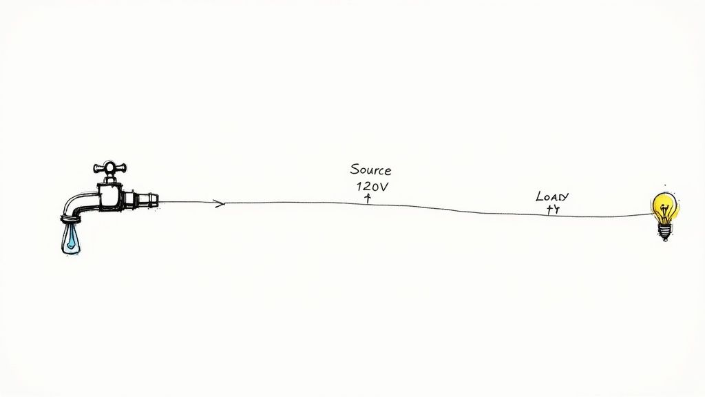
Here's a simple way to think about it. Imagine your electrical system is a garden hose. The water pressure you get at the nozzle is always going to be a little less than what's coming out of the spigot, right? The longer the hose, the more pressure you lose. That's a perfect real-world picture of voltage drop—the unavoidable loss of electrical "pressure" as current flows down a wire. It’s a natural result of a conductor's resistance.
A tiny drop is totally normal and expected. But when that drop gets too big, it becomes a silent killer of performance and a major safety concern. If the voltage reaching a piece of equipment is too low, you’re opening the door to a whole host of problems that can compromise your entire system.
The Real-World Consequences of Ignoring Voltage Drop
Out in the field, ignoring a proper voltage drop calculation has real, tangible consequences. We see it all the time. Equipment starts acting up, fails way too early, or creates genuinely hazardous situations.
The most common headaches include:
Poor Equipment Performance: Motors might run hot or lack the torque they need, which drastically shortens their lifespan. You'll see lights that flicker or look dim, and sensitive electronics can glitch out or just shut down completely.
Energy Waste and Overheating: That "lost" voltage doesn't just vanish—it turns into heat in the wire. Not only does this waste energy and drive up the power bill, but it can also make conductors overheat, melting the insulation and creating a serious fire risk.
Non-Compliance with Standards: The National Electrical Code (NEC) gives us clear guidelines to follow. For instance, NEC 210.19(A) recommends keeping voltage drop on a branch circuit to a maximum of 3%. If you blow past these limits, you're looking at failed inspections and expensive do-overs.
Empowering Your Designs with Accurate Formulas
For anyone designing or installing electrical systems, getting a handle on voltage drop formulas isn't optional—it's fundamental. These calculations are what allow you to pick the right size wire for a specific load and distance, guaranteeing that equipment gets the voltage it needs to run properly.
A huge part of this is knowing how to express the voltage drop as a percentage of your starting voltage. If you need a quick refresher on the concept, checking out a guide on understanding percentages can be incredibly helpful.
Of course, with AC circuits, other factors like impedance and the load's power factor come into play and can affect voltage loss. We dive deeper into this in our guide explaining the power factor definition and its impact. By getting ahead of these variables, you're not just building a system that's safe and efficient—you're building one that's tough and reliable for years to come.
Cracking the Code: The Variables in Every Voltage Drop Formula
Before you can punch numbers into a calculator, you have to speak the language. Think of each voltage drop formula as a short sentence—the variables are the words, and you need to know what they mean to understand the story.
Getting this right is everything. It’s like baking a cake; you wouldn't just start throwing ingredients in a bowl without knowing the difference between flour and salt. In our world, mixing up the variables leads to circuits that are inefficient at best and unsafe at worst.
Let's break down the essential players one by one.
Current (I): The Electrical Workload
Current (I), measured in Amperes (Amps), is the amount of electricity actually flowing through the wire. Remember our garden hose analogy? Current is the volume of water you're trying to push through. The more water, the more pressure you lose from end to end.
It’s the same with electricity. The higher the current, the bigger the voltage drop. A beefy motor pulling 20 Amps is going to cause a much more significant voltage sag than a small LED light pulling 1 Amp, even on the same exact wire. Simply put, current is the primary driver here—it’s the workload you’re asking the circuit to handle.
Length (L): How Far the Electrons Have to Travel
Length (L) is the one-way distance the wire runs, from the panel to the piece of equipment. You'll typically measure this in feet (ft).
Now, here’s a critical detail: electricity needs a complete path to flow. It has to go out to the load and back to the source. The good news is that most common voltage drop formulas already account for this round trip by including a multiplier (like the number 2 for a standard single-phase circuit).
The logic is straightforward. The longer the wire, the more resistance the current encounters, and the more voltage you lose. A 200-foot run will have twice the voltage drop of a 100-foot run, all else being equal.
Here's a classic rookie mistake: using the total wire length (for example, 200 feet out and 200 feet back = 400 feet) for 'L' when the formula already has a built-in multiplier for the round trip. Always use the simple one-way distance for 'L' to avoid accidentally doubling the length and getting a wildly incorrect result.
Conductor Properties: The Wire Itself
The wire you choose plays a huge role, and it comes down to two main things: what it’s made of and how big it is.
The 'K' Factor: This is just a simple constant that represents the electrical resistivity of a given material. It saves you from doing messy physics calculations on the fly. For copper, the K-factor is around 12.9. For aluminum, it’s higher, at about 21.2. That tells you aluminum is more resistive than copper, so it will cause a larger voltage drop for the same size and length.
Circular Mils Area (CMA): This is the cross-sectional area of the wire. Think of it as the width of the pipe. A bigger wire has a higher CMA, giving the electrons more room to flow and reducing the overall resistance. Voltage drop and CMA have an inverse relationship—when you increase the wire size (a bigger CMA), the voltage drop decreases.
These four pieces—Current (I), Length (L), K-Factor (K), and CMA—are the foundational building blocks you'll find in almost every basic voltage drop formula. Once you get a feel for how they interact, you'll be able to tackle these calculations with confidence on any job.
To make it even clearer, here’s a quick-reference table summarizing these key players.
Table: Key Variables in Voltage Drop Formulas
Variable Name
Symbol
Standard Unit
Impact on Voltage Drop
Current
I
Amperes (Amps)
Increases voltage drop. More current means more loss.
Length
L
Feet (ft)
Increases voltage drop. Longer wires mean more loss.
Conductor K-Factor
K
(Constant)
Increases voltage drop. Higher K means more resistance.
Circular Mils Area
CMA
Circular Mils
Decreases voltage drop. Larger wires mean less loss.
Keep this table handy as you start working through the formulas. Seeing how each variable pushes the final result up or down is the key to truly understanding what’s happening in your circuits.
Alright, let's get this section sounding like it was written by an experienced pro who's spent years in the field. Here’s a complete rewrite, focusing on a natural, human voice while preserving all the critical technical details.
Running the Numbers for DC and Single-Phase Circuits
Now for the fun part. We've talked about the "what" and "why" of voltage drop, but it's time to put these concepts to work. This is where we take the theory off the page and start plugging in real numbers to solve the kinds of problems you’ll actually see on a job site.
We’ll start with the basics: Direct Current (DC) and single-phase Alternating Current (AC) circuits. These are the bread and butter of most residential and light commercial work, so getting comfortable with these calculations is essential. We'll kick things off with the straightforward DC formula and then build on it to tackle the nuances of single-phase AC.
The Foundational DC Voltage Drop Formula
For any DC circuit—think solar arrays, battery banks, or low-voltage LED lighting—the math is refreshingly simple. You don't have to worry about weird things like impedance or power factor just yet, which makes it the perfect place to start.
The formula you'll see most often is:
VD = (2 x K x I x L) / CMA
Let's do a quick roll call of the variables in this equation:
VD is the Voltage Drop you're solving for (in volts).
2 is there because the current has to make a round trip—from the source to the load and all the way back.
K is the resistivity of the wire material. It's a constant: 12.9 for copper and 21.2 for aluminum.
I is the current, or load, on the circuit (in amps).
L is the one-way distance of the wire run (in feet).
CMA is the Circular Mils Area, which is just a technical way of saying the wire's cross-sectional area.
The easiest way to think about this formula is as a tug-of-war. Everything on top (K, I, L) makes the voltage drop worse. The one thing on the bottom (CMA) makes it better. This simple relationship shows you instantly that your most powerful weapon against voltage drop is using a bigger wire with a larger CMA.
A Practical DC Calculation Example
Let's put this into a real-world scenario. Imagine you're wiring up a DC water pump that's 200 feet from the battery bank. The pump pulls 15 amps, and you're thinking of using 10 AWG copper wire. A quick look at a wire chart tells you that 10 AWG has a CMA of 10,380.
Let's plug it all in:
VD = (2 x 12.9 x 15 x 200) / 10,380
VD = 77,400 / 10,380
VD ≈ 7.46 Volts
So, what does that number mean? If your source is a 48V battery system, losing 7.46V is a 15.5% drop. That’s way too high and far outside of any acceptable limit. This quick calculation proves that 10 AWG wire is undersized for this run; you need to step up to a bigger conductor.
Moving to Single-Phase AC Circuits
When we jump over to AC circuits, things get a little more complicated. Now, on top of the wire's basic resistance, we also have to deal with reactance (X) and the load's power factor (PF).
For short runs powering simple resistive loads (like old-school incandescent bulbs or electric heaters), you can often get away with using the DC formula as a "good enough" estimate. But once you start dealing with longer distances or circuits feeding motors and modern electronics, you need a more precise formula that accounts for the total opposition to current flow, known as impedance (Z).
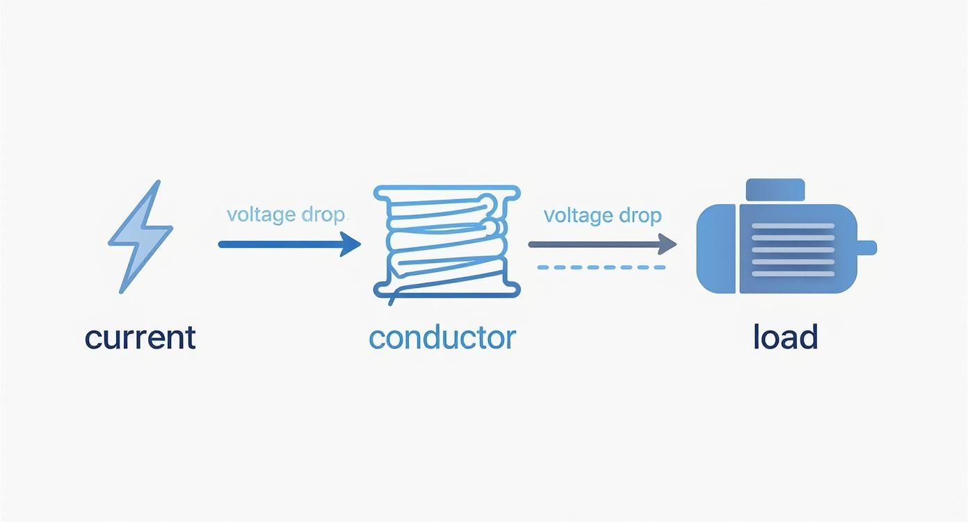
This is a great visual for how all these pieces fit together.
It really drives home that as current travels down a wire to do its job, a loss of voltage is just an unavoidable part of the process.
The More Precise Single-Phase AC Formula
For AC calculations where you need to be spot-on, especially with loads that have a poor power factor, we need to bring out the more advanced formula:
VD = 2 x L x [R x cos(θ) + X x sin(θ)] x I
Okay, don't let this one scare you. Here’s what the new terms mean:
R is the wire's AC resistance (per 1,000 feet).
X is the wire's reactance (per 1,000 feet).
cos(θ) is simply the power factor of the load.
sin(θ) is the reactive factor of the load.
You don't have to guess these values; you can find R and X in tables right in the NEC, specifically in Chapter 9 (Table 8 and Table 9). While the formula looks a bit intimidating, it’s just accounting for more of the physics happening inside the wire.
Key Takeaway: The simple DC formula is fantastic for quick checks and basic circuits. But for any circuit with motors, transformers, or long runs where precision matters, the detailed AC formula is what the pros use.
This drive for accuracy isn't a new trend. The formulas we use have been fine-tuned over decades to meet real-world engineering demands. The basic formula is really just an adaptation of Ohm’s law, expanded to VD = 2 × I × R × L to account for the total length of the circuit path. This approach helps engineers and electricians keep voltage drop under the widely accepted 3-5% limit, a core principle baked into standards like the NEC to keep installations safe and efficient. For a deeper dive, the folks at Electrical Engineering Portal have some great resources on these calculation methods.
Mastering Calculations for Three-Phase Systems
While single-phase power keeps the lights on at home, three-phase power is the undisputed workhorse of the commercial and industrial world. It's the force behind heavy machinery, massive motors, and complex equipment. But this step up in power brings a slight, but critical, twist to our voltage drop formula.
Three-phase systems are a different beast altogether. Instead of one wave of alternating current, you have three separate currents, each out of sync with the others. This interaction delivers a much smoother, more consistent flow of power, which is ideal for big motors and efficient long-distance transmission.
Because the physics are different, we can't just recycle the single-phase formula. We need an equation that accounts for how these three phases work together.
The Go-To Three-Phase Voltage Drop Formula
For nearly every real-world, three-phase circuit you'll encounter, the formula is a simple tweak on the one we already know. It’s clean, reliable, and gets the job done.
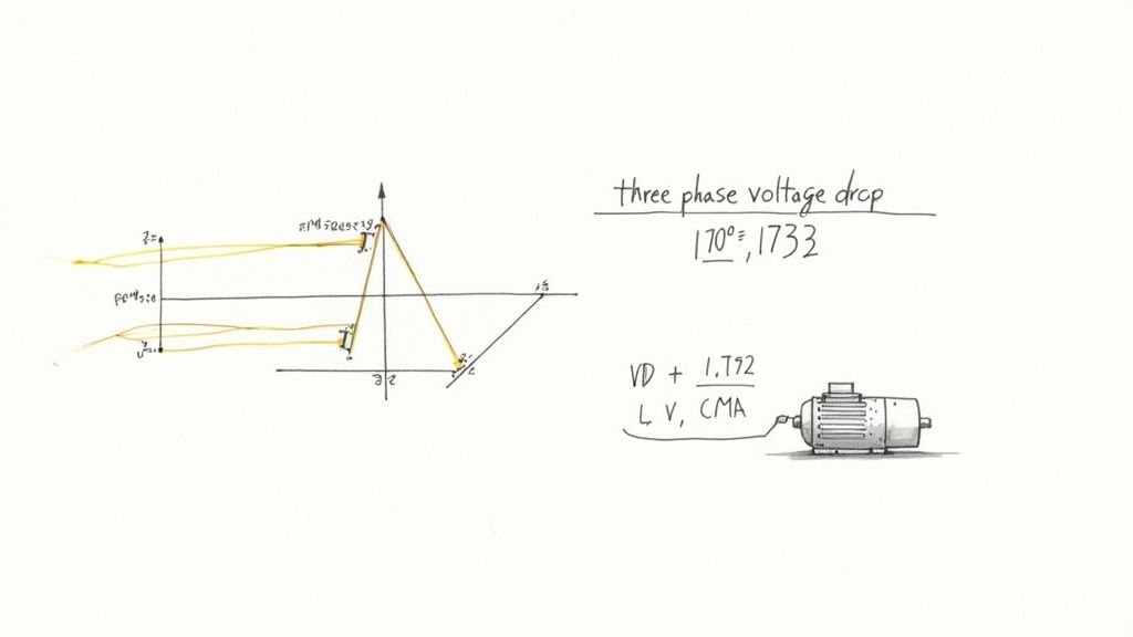
Here’s the standard formula for three-phase voltage drop:
VD = (1.732 x K x I x L) / CMA
Look familiar? It's almost identical to the single-phase version, but we've swapped out the number 2 for 1.732.
What's with 1.732? That number isn't just pulled out of thin air—it’s the square root of 3 (√3 ≈ 1.732). In a balanced three-phase system, this value mathematically bridges the gap between the voltage on a single phase and the line-to-line voltage, keeping our calculations accurate.
Putting the Three-Phase Formula to Work
Let's run through a common job site scenario. You’re wiring up a 480V, three-phase motor for a conveyor system in a factory. The motor sits 300 feet from the control panel and pulls 25 amps at full load. You've decided to use 8 AWG copper wire, which has a CMA of 16,510.
Time to plug those numbers into our formula.
Line up your variables:
1.732: Our three-phase constant.
K: 12.9 (the K-factor for copper).
I: 25 Amps (the load current).
L: 300 feet (the one-way distance).
CMA: 16,510 (for 8 AWG wire).
Do the math:
VD = (1.732 x 12.9 x 25 x 300) / 16,510
VD = 167,058 / 16,510
VD ≈ 10.12 Volts
The calculation shows we can expect to lose about 10.12 volts on the way to the motor.
Is This Voltage Drop Acceptable?
Now for the final, crucial step: putting that number in context. Is a 10.12V drop on a 480V system a big deal? We find out by calculating the percentage drop.
Percentage Drop = (Voltage Drop / Source Voltage) x 100
Percentage Drop = (10.12V / 480V) x 100
Percentage Drop ≈ 2.1%
At 2.1%, we are comfortably under the 3% limit the NEC recommends for a single branch circuit. Our 8 AWG wire is the right choice for the job, ensuring the motor gets the voltage it needs to run efficiently without overheating or failing down the line.
When you're designing commercial EV charging solutions, getting these three-phase calculations right is absolutely essential. The high power demands and complex layouts leave no room for error.
This process is critical for any three-phase load, from HVAC units to industrial machinery. Motors are especially sensitive to low voltage; it makes them draw more current, which generates excess heat. For sophisticated setups with Variable Frequency Drives (VFDs), clean and stable power is non-negotiable. Running this simple calculation can prevent costly equipment damage and keep the whole system reliable.
Navigating NEC Rules for Voltage Drop
Knowing how to crunch the numbers with voltage drop formulas is only half the battle. The other half is understanding the industry standards that tell you what’s actually acceptable in the field. For anyone working in the United States, that guidance comes straight from the National Electrical Code (NEC).
The NEC is the bible for safe electrical design and installation. While most of the code is full of hard-and-fast rules you have to follow, its take on voltage drop is a little different. The recommendations show up in what the NEC calls "Informational Notes."
Technically, these notes aren't enforceable laws. But in the real world? They're treated as gospel by professionals. Ignoring them is a recipe for designing an inefficient, problematic, or even unsafe system.
The 3% and 5% Rules of Thumb
The most critical recommendations are boiled down to two simple percentages. These are the guidelines that electricians and engineers live by to ensure every installation is a quality one.
NEC 210.19(A) Informational Note No. 4: This note advises keeping the voltage drop on a single branch circuit to 3% or less. This is the run from the breaker in the panel out to the farthest outlet or light fixture.
NEC 215.2(A)(1) Informational Note No. 2: This one looks at the bigger picture. It recommends the total voltage drop—across the feeder wires and the branch circuit combined—should not exceed 5%.
Think of it like this: the 3% rule is there to protect the individual appliance or piece of equipment plugged in at the end of the line. The 5% rule protects the health of the entire electrical system, all the way from the main service to that last plug.
If you’re dealing with more complex distribution systems, knowing how feeders and branch circuits are laid out is crucial. You can dive deeper into specific setups in our guide to the NEC tap rule.
To put it all together, here is a quick reference table for the NEC's recommendations.
NEC Recommended Voltage Drop Limits
This table summarizes the key guidelines from the NEC Informational Notes, providing a clear reference for designing efficient and reliable circuits.
Circuit Type
Recommended Maximum Voltage Drop (%)
NEC Reference
Branch Circuit Only
3%
210.19(A) Informational Note No. 4
Feeder + Branch Circuit Combined
5%
215.2(A)(1) Informational Note No. 2
Sticking to these limits isn't just about following the code; it’s about good engineering that pays off in the long run.
By sticking to these percentages, you're proactively protecting sensitive electronics, helping motors run cooler and last longer, and preventing the kind of sneaky energy waste that inflates a power bill. It’s a best practice that separates truly professional work from the rest.
Why These Percentages Matter More Than Ever
In today's world, these guidelines aren't just suggestions—they're critical. We're plugging in more high-draw, sensitive electronics than ever before, and there’s simply no room for sloppy voltage. A drop that might have just dimmed an old incandescent bulb can cause serious headaches for modern tech.
Take Electric Vehicle (EV) chargers, for example. An EV charger running on low voltage will charge the car slower and waste electricity in the process. Or think about solar power systems. Every bit of voltage lost between the panels and the inverter is power you can't sell back or use, directly hitting the system's return on investment.
This isn't just a local problem. Energy losses from voltage drop are a huge source of grid inefficiency, with some estimates suggesting that 5-7% of all electricity generated is lost before it's ever used. It’s why in critical DC systems, like commercial solar arrays, designers have long followed an even stricter 2% voltage drop limit to squeeze every last watt out of the system.
At the end of the day, treating the NEC's informational notes as hard requirements is the mark of a true professional. It shows you’re committed to building systems that are not just functional, but efficient, safe, and reliable for years to come.
Avoiding Common Calculation Mistakes
Even the most seasoned pros can get tripped up by simple mistakes when running a voltage drop calculation. It happens. A misplaced decimal point or a forgotten variable can domino into undersized wires, failed inspections, and equipment that just won't perform right.
Getting the math right from the start is non-negotiable. The best way to do that is to know where the common pitfalls are. Think of this as your pre-flight checklist—a quick run-through to make sure your design is built on a solid, accurate foundation.
Forgetting the Round Trip
This one is probably the most common mistake in the book: using the one-way wire length and forgetting that electricity has to make a return trip. It needs a complete circuit to flow, from the source, out to the load, and all the way back again.
Thankfully, most standard voltage drop formulas for single-phase circuits are designed to handle this for you. They already include a multiplier of 2. Where people get into trouble is by either forgetting this or manually doubling the length again in a formula that already does it. That'll throw your results off by a factor of two, leading to some seriously oversized (and expensive) wire.
Rule of thumb: Always use the simple one-way distance for the Length (L) variable in your formula. Trust the formula to handle the round-trip math. For three-phase systems, the 1.732 constant does something similar, accounting for the system's physics.
Ignoring Temperature and Conductor Type
A wire isn't just a wire; its properties change with its environment and what it's made of. Two key details often get missed:
Ambient Temperature: Resistance goes up as things get hotter. A wire snaked through a blistering hot attic or bundled in a crowded conduit will have a higher voltage drop than one sitting in a cool, open-air environment. You have to apply the right temperature correction factors from the NEC when conditions call for it.
Wrong 'K' Factor: The resistivity constant, known as the 'K' factor, is completely different for copper (12.9) and aluminum (21.2). If you accidentally plug in the copper value for an aluminum run, your calculation will show a much lower voltage drop than what you'll get in reality. That's a classic recipe for an undersized wire.
Misinterpreting AC Circuit Factors
Alternating current brings a few more variables into the mix that you just don't see in DC circuits. The biggest one people forget is power factor, especially on circuits with motors or other inductive loads. A low power factor means the circuit has to draw more total current to do the same amount of work, and more current means more voltage drop.
For short, simple AC runs, you can often get away with the basic formula as a decent estimate. But for longer distances or circuits feeding motors and other inductive loads, you really need to use the more detailed formula that includes impedance (both resistance and reactance). It's the only way to get precise, reliable results every single time.
Got Questions? We've Got Answers
Even after you've run the numbers, a few practical questions always seem to pop up. Let's tackle some of the most common ones we hear from folks in the field to clear up any lingering confusion.
How Much Voltage Drop Is Too Much?
While the NEC gives us guidance in informational notes, the industry has pretty firm best practices. Sticking to these isn't just about following rules—it's the hallmark of a quality installation that keeps equipment running efficiently for the long haul.
Here are the numbers to live by:
A branch circuit (think panel to the final outlet) should never drop more than 3%.
The total system, adding the feeder and the branch circuit together, shouldn't exceed a combined 5% drop.
Pushing past these limits is asking for trouble. You'll see poor performance, wires getting warmer than they should, and you could even shorten the life of the equipment you're trying to power.
Why Is the Three-Phase Formula Different?
It really boils down to the physics of how the power gets from point A to point B. In a simple single-phase circuit, the formula uses a multiplier of 2 because it has to account for the current traveling out on one wire and returning on the other—a complete round trip.
But a balanced three-phase system is a different animal. The return currents are essentially carried on the other phase conductors. The math gets a bit more involved, but the bottom line is that you use the square root of 3 (which is roughly 1.732) instead of 2. This number perfectly captures the push-and-pull interaction between the phases.
Simply put, that 1.732 in the three-phase voltage drop calculation formulas isn't just a random number. It’s the precise constant needed to accurately model how a three-phase circuit behaves in the real world.
Does Power Factor Always Matter for AC Circuits?
Good question. The answer is no, not always.
If you're dealing with simple resistive loads—things like old-school incandescent bulbs or basic electric heaters—the power factor is nearly perfect, right around 1.0 (unity). For these circuits, especially on shorter runs, you can often get away with using the simpler DC voltage drop formula for a "good enough" estimate.
However, the moment you start powering inductive loads like motors, transformers, or big banks of fluorescent or LED lights, power factor becomes a huge deal. A low power factor means the circuit has to draw more total current to do the same amount of work, and that extra current jacks up your voltage drop. For those jobs, you absolutely have to use the more detailed AC formula that accounts for both resistance (R) and reactance (X) to get a number you can trust.
At E & I Sales, we provide the motors, controls, and system integration expertise to ensure your designs are efficient and reliable from day one. For help specifying the right components for your next project, visit us at https://eandisales.com.
Picture this: you've just been handed a frosty mug of beer.
The whole thing—glass, beer, and foam—is the total power your facility is pulling from the grid. But it's only the actual beer that does you any good. That's your Real Power, the stuff that actually runs your motors and keeps the lights on.
That thick layer of foam at the top? It takes up space in the mug, but you can't drink it. That's your Reactive Power. It's not doing any real work, but the utility still has to supply it.
Power factor is simply the ratio of the good stuff (the beer) to the entire mug.
So, What Is Power Factor, Really?
At its heart, power factor is a straightforward measure of electrical efficiency. It’s a number between 0 and 1 that tells you how effectively your equipment is turning electricity into useful work.
A perfect score is 1.0 (unity). This means every last drop of power sent to your facility is being put to productive use. But if your power factor is, say, 0.75, you're only using 75% of the power you're drawing. The other 25% is essentially wasted energy that's just circulating in your system.
This isn't just some abstract number, either. That "wasted" power puts a real strain on your cables and transformers. More importantly, it shows up on your utility bill. Power companies have to generate and deliver that extra non-productive power, which stresses their grid, so they often hit facilities with low power factor with some hefty penalties.
The Three Amigos of Electrical Power
To really get a handle on power factor, you need to understand the three distinct types of power that make it up. Engineers often talk about the "power triangle," but let's stick with our beer analogy.
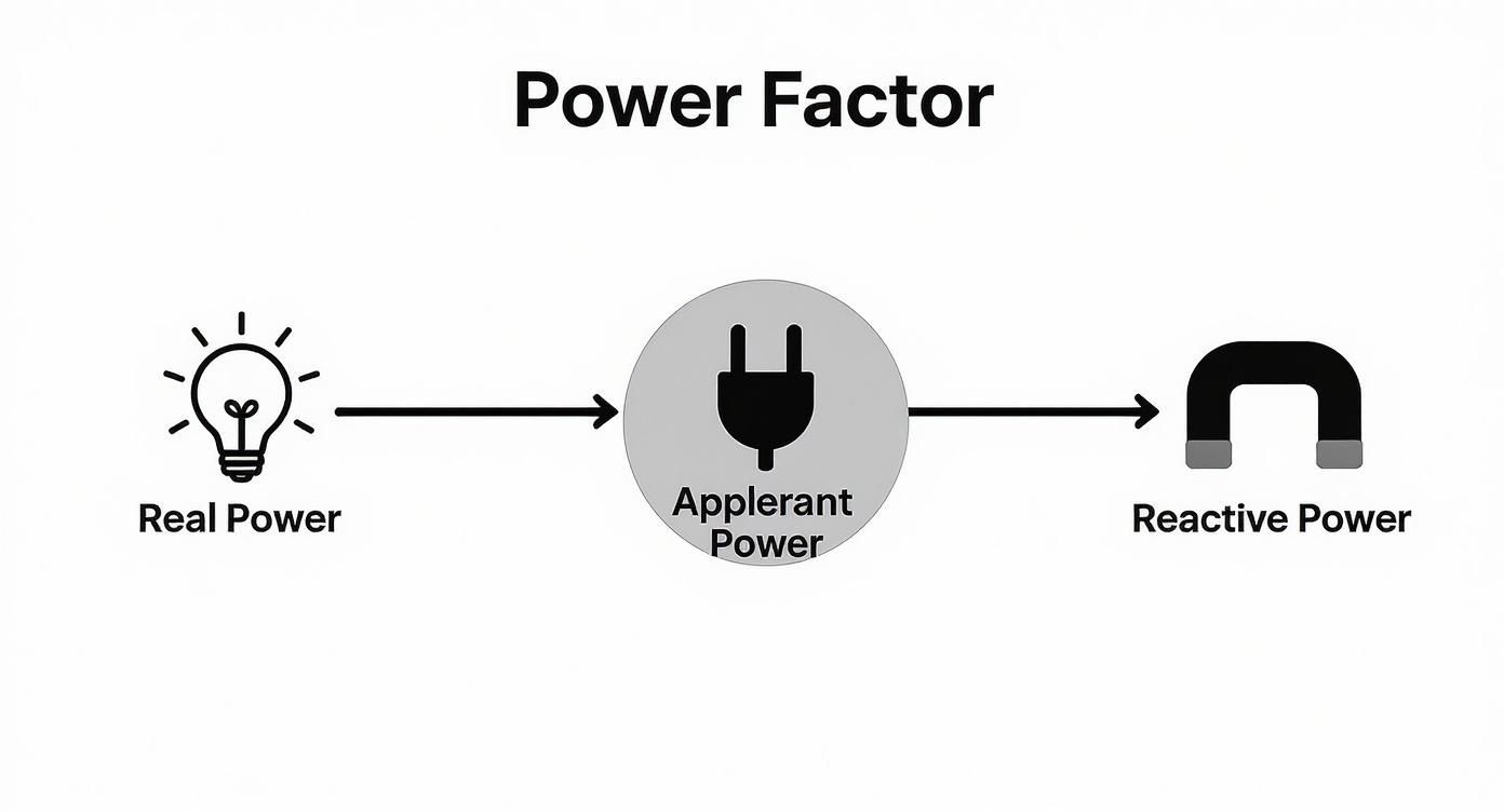
Real Power (kW): This is the beer. It’s the power that gets the job done—turning motor shafts, heating elements, and lighting up your plant. It’s measured in kilowatts (kW), and it's what you actually want and need.
Reactive Power (kVAR): This is the foam. It's the power required by equipment like motors and transformers just to create their magnetic fields. While it’s necessary for them to operate, it performs zero tangible work. It's measured in kilovolt-amperes reactive (kVAR).
Apparent Power (kVA): This is the whole mug. It’s the combination of Real Power and Reactive Power, representing the total power your utility has to supply to your doorstep. This is measured in kilovolt-amperes (kVA).
Here's a quick cheat sheet to keep these straight:
The Three Types of Electrical Power at a Glance
Power Type
What It Does
Unit of Measurement
Analogy (Beer Mug)
Real Power
Performs actual, useful work.
Kilowatts (kW)
The beer
Reactive Power
Creates and sustains magnetic fields.
Kilovolt-Amperes Reactive (kVAR)
The foam
Apparent Power
The total power supplied by the utility.
Kilovolt-Amperes (kVA)
The entire mug
Understanding these three components is the key to unlocking better efficiency.
Power factor is a fundamental concept in electrical engineering, defined as the ratio of real power (measured in watts, W) to apparent power (measured in volt-amperes, VA) in an alternating current (AC) power system. A power factor of 0.8 means that only 80% of the electrical power is doing useful work, while 20% is wasted. You can explore a more detailed technical breakdown of the power factor on Wikipedia.
Ultimately, getting a grip on what power factor means is the first, most crucial step toward a more efficient facility. When you improve your power factor, you’re not just trimming energy waste—you're cutting operating costs and freeing up electrical capacity to help your plant grow.
Identifying the Causes of Poor Power Factor
Okay, so you get the concept of power factor. But knowing the definition and finding the real-world culprits dragging it down in your facility are two different things. Poor power factor isn’t some random fluke; it’s a direct result of the equipment you fire up every single day.
The main offenders are devices that need reactive power to do their job, which in turn creates a phase shift between voltage and current.
This is almost always tied to something called inductive loads. Just think of anything that runs using magnetic fields. To build and maintain those fields, this equipment constantly sips reactive power (kVAR)—the "foam" in our beer analogy. This isn't "working" power, but it still puts a strain on your electrical system, making the current lag behind the voltage.
The more of these inductive loads you have running, the bigger that lag gets, and the further your power factor plummets. Finding these machines is the first step to fixing the electrical waste in your plant.
This diagram really helps visualize how the different types of power relate to each other and define your power factor.
As you can see, the Apparent Power you pull from the utility is a combination of the Real Power doing useful work and the Reactive Power that isn't. When that reactive slice of the pie gets too big, your efficiency tanks.
Common Inductive Loads in Industrial Settings
So, what specific gear should you have your eye on? In most plants and commercial buildings, a few usual suspects are responsible for almost all the reactive power demand.
AC Induction Motors: These are, without a doubt, the single biggest contributors. They are the absolute workhorses of industry, running everything from pumps and fans to conveyors and compressors. Their entire operation depends on creating a rotating magnetic field, which is a massive consumer of reactive power, especially when they aren't fully loaded.
Transformers: Every facility has transformers stepping voltage up or down. Just like motors, they rely on magnetic induction and need a steady diet of reactive power to function.
Welding Equipment: Arc welders and similar induction-based machines also generate powerful magnetic fields to operate, adding to the inductive load on your system.
High-Intensity Discharge (HID) Lighting: If you’re still using older lighting like mercury vapor or high-pressure sodium lamps, their magnetic ballasts are highly inductive and contribute to the problem.
The combined impact of these loads can be huge. A single motor might not seem like a big deal, but hundreds of them running across a facility can easily drag the plant's power factor down to 0.80 or lower, and that’s when you start seeing those painful utility penalties on your bill.
Why Lightly Loaded Motors Are a Problem
Here’s a common misconception: a motor running at partial capacity must be more efficient, right? Wrong. When it comes to power factor, it’s actually the opposite.
An induction motor draws a fairly constant amount of reactive power just to keep its magnetic field energized, no matter how much mechanical work it’s actually doing.
This means a motor chugging along at 50% of its rated load will have a much worse power factor than one running at 90% load. While the real power (kW) it uses goes down, the reactive power (kVAR) it needs stays pretty much the same. Suddenly, the "foam" (kVAR) takes up a much larger percentage of the total "mug" (kVA).
This is exactly why sizing motors correctly for the job is so critical—not just for mechanical performance, but for your electrical health. If you think you might have oversized or underloaded motors, it’s worth investigating your options. You can learn more about the wide range of electric motors available to make sure you've got the right tool for the job. Pinpointing and fixing these specific sources of inefficiency is the only way to get your power factor back where it needs to be.
The Real-World Costs of a Low Power Factor
Understanding the theory behind power factor is one thing. Watching it hit your bottom line makes it a problem you can't afford to ignore.
A low power factor isn't just a technical footnote for engineers; it's a financial anchor dragging on your profitability. The consequences pop up everywhere, from glaring penalties on your utility bill to hidden stress on your entire electrical system.
When you have poor efficiency, you're literally paying for electricity you can't even use. The utility still has to generate and transmit that non-productive reactive power, and you can be sure they’re passing that cost right along to you.
Direct Financial Penalties from Your Utility
The most immediate—and painful—cost of a low power factor comes straight from your electricity provider. Most utilities tack on a power factor surcharge or penalty for their commercial and industrial customers.
This isn't just some minor fee. It’s a serious financial motivator designed to push businesses to operate more efficiently and reduce the strain on the grid.
These penalties kick in when your facility's power factor drops below a certain threshold, typically 0.95 or 0.90. If your plant is humming along at a 0.85 power factor, you're not just paying for the real power (kW) you actually used. You're also getting an extra bill for the excessive reactive power (kVAR) you demanded.
These surcharges can bloat a facility's electricity costs by several percentage points. For a medium-sized operation, that can easily add up to thousands—or even tens of thousands—of dollars a year. It's a direct, measurable expense that bleeds your budget month after month.
Increased Energy Losses and Wasted Money
Beyond the utility bills, a low power factor creates expensive problems inside your own facility. All that extra reactive current sloshing around your system doesn't do any work, but it definitely generates heat. This is all thanks to I²R losses, where "I" is the current and "R" is the resistance of your wiring.
Because a low power factor demands higher total current to deliver the same amount of useful power, your I²R losses climb exponentially. This waste shows up in a few ways:
Wasted Energy: Your cables, transformers, and switchgear get warmer than they should, burning off energy as heat instead of powering your machines. It's electricity you paid for, vanishing into thin air.
Higher Cooling Costs: In places like data centers or climate-controlled production areas, that extra heat forces your HVAC system to work overtime, inflating your energy bills even further.
These internal losses might not be a separate line item on a bill, but they represent a constant and significant financial leak.
Crippled System Capacity and Avoidable Upgrades
This might be the most damaging consequence in the long run. A low power factor puts a chokehold on your entire electrical distribution system. Your transformers, switchgear, and cables are all rated for a maximum apparent power (kVA). When useless reactive current hogs that capacity, there’s less room for the real power that actually makes you money.
Picture this: A facility's main transformer is running at 95% of its kVA capacity. But because the power factor is a dismal 0.75, only about 71% of that capacity is doing productive work. The rest is just electrical dead weight.
Now, let's say you need to add a new production line.
Even though you have enough real power headroom, your transformer is screaming for help. Your only options are a costly, disruptive upgrade of your electrical service or fixing the power factor. By simply improving the power factor to 0.95 or higher, you could free up over 20% of your system's capacity without buying a single new transformer. That new equipment could be installed tomorrow, avoiding a massive capital expense.
This is exactly why a poor power factor is often called a "capacity thief." It steals the potential of the infrastructure you already own. In fact, data shows that poor power factor can drive system losses 20-30% higher than in a well-run facility. To dig deeper into these figures, you can learn more about the economic impact of the power factor from leading industry sources.
How to Measure and Analyze Your Power Factor
Alright, let's move from theory to action. To fix a low power factor, you first have to figure out what's actually happening on your shop floor. It's all about gathering the right data, identifying the main culprits, and seeing exactly where the utility is hitting you on your bill.
The good news? You don't need to be a seasoned electrical engineer to get started. The first clues are usually hiding in plain sight.
Start with Your Utility Bill
Your monthly electricity bill is the absolute best place to start your investigation. Utilities love to bill for poor efficiency, but they don't always call it the same thing.
Comb through the line items and look for these tell-tale signs:
Power Factor Surcharge/Penalty: This one is pretty straightforward. It's a direct penalty for dropping below their target, which is often 0.95.
kVAR Demand Charge: Some utilities bill you directly for peak reactive power demand. Think of this as a charge for all that "foam in the beer" your equipment is demanding from the grid.
kVA Billing: This is a sneaky one. If your bill is based on apparent power (kVA) instead of just real power (kW), a low power factor is guaranteed to inflate your demand charges.
If you spot any of these, you have your smoking gun. Poor power factor is already costing you money, month after month. This is the ammo you need to build a business case for fixing it.
Using the Right Diagnostic Tools
While your utility bill confirms you have a problem, you need professional tools to pinpoint the cause. The go-to instrument for this job is a power quality analyzer.
This is a specialized piece of gear you can clamp onto your electrical feeders to record incredibly detailed data over time. It measures everything: voltage, current, real power (kW), reactive power (kVAR), apparent power (kVA), and, of course, power factor.
By logging this data, you can see how your power factor fluctuates as different machines kick on and off throughout the day. This is how you connect a low power factor reading to a specific piece of equipment or operational schedule.
Conducting a Basic Power Factor Study
With an analyzer in hand, you can conduct a quick study to get a clear picture of your system's health. It’s a pretty logical process.
Here’s how a successful study usually plays out:
Measure at the Main Service: First, hook up the analyzer right where power enters your building. This gives you the big-picture view—the exact power factor your utility is seeing and billing you for.
Identify Large Inductive Loads: Walk the floor and make a list of your biggest potential offenders. We're talking large motors, compressors, grinders, and welders. These are your prime suspects.
Measure at Key Distribution Panels: Now, move the analyzer downstream to the panels feeding those high-horsepower motor loads. This is how you isolate which areas of the plant are the biggest contributors to the problem.
Analyze the Data: It's time to connect the dots. Compare the power factor readings from different spots. If you see a major drop at a panel feeding a motor control center, you've found exactly where your reactive power demand is coming from.
This systematic approach takes a vague, facility-wide problem and turns it into a targeted hit list of inefficient equipment. The data you gather here is the foundation for designing a correction strategy that actually works.
So, you’ve found a low power factor in your facility. What’s next?
Fixing it, of course. The good news is that this is a well-understood problem with tried-and-true solutions. Think of it like rebalancing a wobbly tire—the goal is to counteract the forces throwing your system out of whack and restore smooth, efficient operation.
The core issue, as we've seen, is the excessive reactive power (kVAR) that inductive loads like motors demand from the grid. The fix is surprisingly simple in concept: supply that reactive power right at the source. Doing this takes the strain off the utility, cuts the total current flowing through your wiring, and nudges your power factor back toward the perfect 1.0.
Capacitor Banks: The Go-To Solution
For most industrial and commercial applications, the most common and cost-effective tool in the toolbox is the capacitor bank.
If inductive loads are the problem, capacitors are the antidote. They generate leading reactive power, which directly cancels out the lagging reactive power that motors and transformers gobble up.
Imagine your big induction motor is constantly "borrowing" reactive power from the utility to keep its magnetic fields spinning. A capacitor bank acts like a small, on-site energy reservoir that "lends" that power to the motor instead.
Because this transaction now happens locally, that reactive power no longer has to travel all the way from the power plant. This one change dramatically lowers the total current in your system, which cuts down on heat losses and frees up electrical capacity you didn't even know you had.
Fixed vs. Automatic Capacitor Banks
Not all capacitor banks are built the same. Picking the right type—fixed or automatic—is a critical decision that depends entirely on how your facility operates.
Fixed Capacitor Banks: These are the simple, no-frills option. They deliver a constant, unchanging amount of correction. You’ll often see them wired directly to a large, continuously running motor. They are a great "set it and forget it" solution for a single, steady load but are a poor choice for facilities with fluctuating power needs.
Automatic Capacitor Banks (APFC): This is the smarter, more dynamic approach. An APFC panel is a cabinet full of individual capacitor "stages" managed by an intelligent controller. The controller constantly watches your facility's power factor and switches these stages on and off as needed, delivering the perfect amount of correction in real time.
Key Takeaway: For any facility with varying loads—like a factory where machines start and stop all day—an automatic capacitor bank is almost always the right call. It keeps you from over-correcting, which can be just as bad as not correcting at all.
Other Advanced Correction Methods
While capacitors handle the bulk of PFC work, a few other technologies come into play for more specialized or heavy-duty situations.
Synchronous Condensers In massive operations like steel mills or mines, you might find a synchronous condenser. This is essentially a huge synchronous motor running without any mechanical load attached. By tweaking its field excitation, operators can make it generate or absorb massive amounts of reactive power, giving them incredibly precise, dynamic control over the grid.
Active Filters Today's facilities are packed with VFDs, LED lights, and other electronics that create another power quality headache: harmonic distortion. An active harmonic filter is a sophisticated piece of power electronics that not only corrects for power factor but also injects opposing currents to cancel out those damaging harmonics.
This connection between power factor and harmonics is crucial. For a solid foundation, check out our guide on variable frequency drive basics.
To help you navigate these options, here’s a quick comparison of the most common PFC methods.
Comparing Power Factor Correction Methods
Choosing the right technology is key to a successful PFC strategy. This table breaks down the main options to help you decide which approach best fits your facility's needs and budget.
Correction Method
Best For
Pros
Cons
Fixed Capacitor Banks
Individual, constant loads (e.g., a large motor that runs 24/7).
Simple, low cost, easy to install.
Can cause overcorrection if the load turns off; no flexibility.
Automatic Capacitor Banks
Facilities with multiple, varying loads (most manufacturing plants).
Highly efficient, prevents overcorrection, adapts to changing needs.
Higher initial cost, more complex installation.
Synchronous Condensers
Utility-scale or very large industrial applications (mining, steel mills).
Extremely precise and dynamic control; can absorb or generate reactive power.
Very expensive, large physical footprint, requires significant maintenance.
Active Harmonic Filters
Facilities with high levels of non-linear loads (VFDs, electronics).
Corrects PF and eliminates harmonic distortion simultaneously.
Highest cost, primarily a power quality solution with PFC benefits.
Ultimately, the goal is to pick the solution that provides the most effective correction without introducing new problems. For most, an APFC panel hits that sweet spot.
As you can see, the right method depends entirely on your load profile. The growing demand for electric vehicles, for example, makes boosting EV charging efficiency a key area where precise power factor control is essential for managing costs and grid stability.
Common Mistakes and Advanced Considerations
Getting power factor correction right is about more than just bolting a capacitor bank to the wall. It’s a balancing act, and a few common missteps can easily turn your solution into a whole new set of problems.
Two of the biggest tripwires in modern facilities are the risk of overcorrection and the chaotic influence of harmonic distortion.
The Dangers of Overcorrection
Simply throwing capacitors at an inductive load without a deeper look is a classic, and frankly dangerous, mistake. The idea is to neutralize reactive power, not swing the pendulum too far in the other direction.
Overcorrection happens when you have more capacitance online than your current inductive load requires. We see this all the time with fixed capacitor banks wired to motors that cycle on and off. When the motor shuts down, its inductive load disappears, but those capacitors just keep pumping reactive power into a system that has nowhere to put it.
This shoves your system into a leading power factor, which can be just as damaging as a lagging one. The fallout is often immediate and expensive:
System Over-voltage: All that excess capacitive energy has to go somewhere, and it often shows up as a sharp, damaging spike in system voltage. This is poison for sensitive electronics, hard on motor insulation, and a primary cause of nuisance trips on breakers.
Utility Penalties: The utility company doesn't care which direction your power factor is off. Just as they'll bill you for lagging PF, many will hit you with surcharges for a leading PF, too. Your "fix" just became another line item on the bill.
The real takeaway here is that power factor correction has to be dynamic. For any facility with loads that fluctuate, an Automatic Power Factor Correction (APFC) system isn't a luxury—it's essential. It intelligently switches capacitor stages in and out to chase a target PF, keeping you in the sweet spot without ever pushing the voltage too high.
Navigating the Challenge of Harmonics
The other elephant in the room is harmonic distortion. Think of it as electrical noise pollution, and it's absolutely everywhere in a modern plant thanks to the rise of non-linear loads. The biggest offenders? Variable Frequency Drives (VFDs), LED lighting, welders, and even the power supplies in your office computers.
Unlike a clean motor load that draws a smooth AC sine wave, these devices sip current in short, high-frequency gulps. This action injects distorted currents—harmonics—back into your electrical system.
This becomes a five-alarm fire when you introduce standard PFC capacitors. Your system's natural inductance combined with the new capacitors can accidentally create a resonant circuit, tuned perfectly to one of those harmonic frequencies.
When that happens, the circuit acts like an amplifier, taking a small harmonic current and magnifying it to destructive levels. This is where we see capacitor fuses blowing for no apparent reason, transformers overheating dangerously, and sensitive electronics failing mysteriously. Standard capacitor banks simply weren't built for a high-harmonic world. To get a better handle on this, check out our guide on using a harmonic filter for VFD systems.
If your plant relies heavily on VFDs or other non-linear loads, specialized PFC gear is non-negotiable. Detuned capacitor banks include reactors that shift the system's resonant point to a harmless frequency. For an even more robust fix, active harmonic filters act like noise-canceling headphones for your power, electronically eliminating harmonics while also correcting power factor.
At E & I Sales, we specialize in designing and implementing robust electrical solutions that account for these advanced challenges. From engineered UL-listed control panels to turnkey system integration, we provide the expertise to ensure your power factor correction project is safe, effective, and reliable for the long haul. Find out how we can help optimize your facility at https://eandisales.com.
Think of ground fault protection as your electrical system's personal bodyguard. It’s an incredibly fast safety switch that monitors your wiring for any sign of trouble. The moment it detects electricity straying from its intended path—a dangerous situation known as a ground fault—it snaps into action, shutting down the power in a fraction of a second to prevent a nasty electric shock.
That immediate, life-saving response is what makes it so indispensable in our homes, on job sites, and anywhere electricity is used.
What Is Ground Fault Protection and Why Is It Essential
Let's use an analogy. Imagine your electrical circuit is a closed-loop plumbing system. The electricity is like water, flowing from the source, through your tools or appliances, and then returning to the source. Everything is contained.
A ground fault is what happens when that system springs a leak. The electricity escapes its intended path and finds a shortcut to the ground.
That leak can be incredibly dangerous. If a person accidentally becomes that shortcut—say, by touching a faulty piece of equipment while standing in a puddle—the resulting electric shock can be severe, or even fatal. This is precisely where ground fault protection proves its worth.
Protecting People First and Foremost
When we talk about ground fault protection, the number one priority is almost always people. It doesn't take much electrical current to cause serious harm, far less than what it takes to trip a standard circuit breaker. Those breakers are designed to protect equipment and wiring from overheating, not to save a person's life. They simply aren't sensitive enough for the job.
This brings us to the two distinct goals of electrical protection:
Personnel Protection: This is all about preventing electrocution. These devices are fine-tuned to detect tiny, almost imperceptible current imbalances—as little as 4-6 milliamperes—and trip instantly.
Equipment Protection: The focus here is on shielding expensive machinery like motors, generators, and transformers. These systems are designed to stop higher-level ground faults that could lead to fires or catastrophic equipment failure.
While both types of protection are critical, keeping people safe is the non-negotiable mission in nearly every setting.
A ground fault is an unintended electrical path between a power source and a grounded surface. Ground fault protection devices are designed to interrupt this dangerous flow of electricity before it can cause serious injury or death.
The widespread adoption of these systems has fundamentally changed electrical safety for the better. As experts at NK Technologies explain in their resources, a huge number of potential disasters are quietly prevented every day because these devices do their job.
Personnel vs Equipment Protection At a Glance
To really get a feel for these two functions, it helps to put them side-by-side. Think of one as a hyper-alert bodyguard for people and the other as a heavy-duty security guard for your expensive gear.
This table breaks down the key differences:
Aspect
Personnel Protection (e.g., GFCI)
Equipment Protection (e.g., GFPE)
Primary Goal
Prevents electric shock and saves lives.
Prevents damage to electrical equipment and fires.
Sensitivity
Extremely high; trips at very low currents (4-6 mA).
Lower; trips at higher currents (e.g., 30 mA to several amps).
Response Time
Extremely fast, typically within 20-30 milliseconds.
Slower, may have an intentional time delay to avoid nuisance trips.
Common Location
Bathrooms, kitchens, outdoor outlets, and wet areas.
Main service panels, feeders, and large motors.
Ultimately, both play a vital role in a safe, reliable electrical system. One keeps you safe, and the other keeps your operations running without burning down.
Understanding Different Ground Fault Protection Devices
While the goal of ground fault protection is always the same—stopping dangerous electrical currents in their tracks—the tools for the job aren't one-size-fits-all. Different devices are engineered for very different scales, from protecting a single person plugging in a hairdryer to safeguarding an entire industrial plant.
Think of it like securing a building. You’d use a simple lock on an interior office door, but a far more complex system for the main entrance and vault. Electrical safety is no different. It uses a whole range of devices to build a complete safety net, layer by layer. Let’s break down the most common players you'll run into.
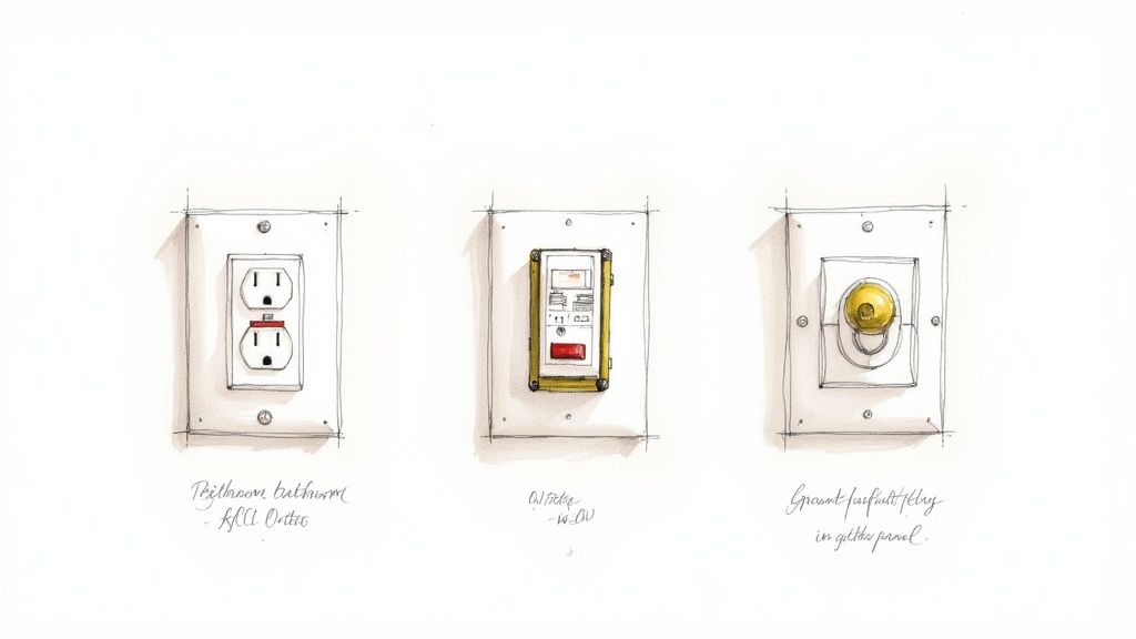
Ground-Fault Circuit Interrupters (GFCIs)
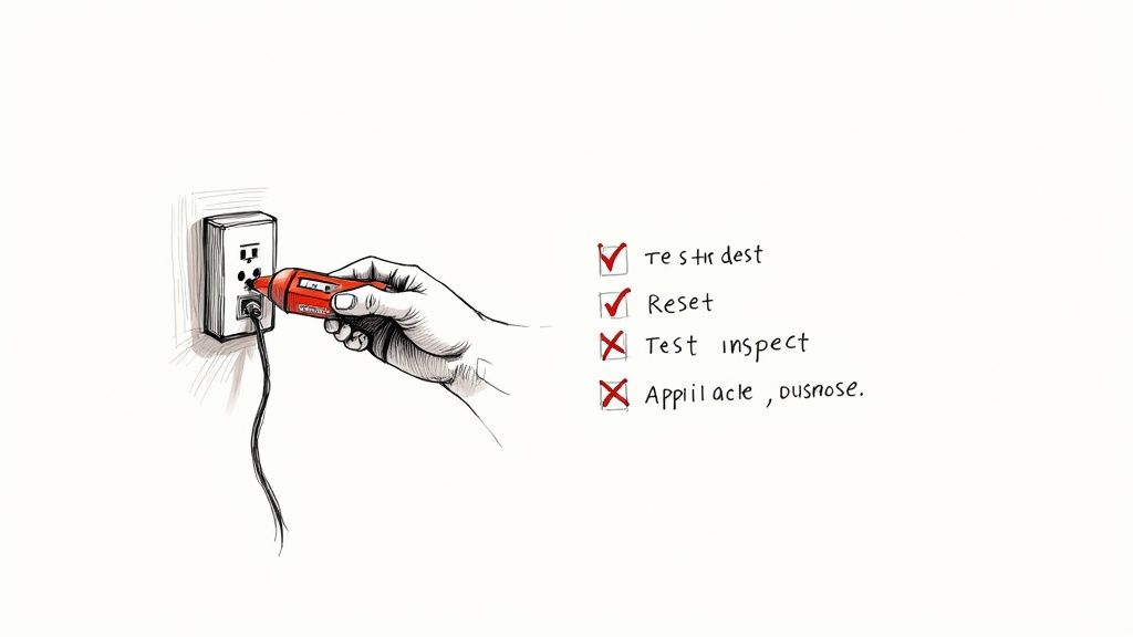
For most people, the GFCI is the face of ground fault protection. It’s that outlet with the little "TEST" and "RESET" buttons you see in kitchens, bathrooms, and garages. The GFCI is your personal bodyguard, standing watch right at the point of use.
How it works is both simple and brilliant. A GFCI constantly monitors the electricity flowing out on the "hot" wire and coming back on the "neutral" wire. In a healthy circuit, these two currents are perfectly balanced.
But if that balance is off by just a tiny amount—as little as 4 to 6 milliamperes—the GFCI assumes the missing current has found another path to ground. A dangerous path, possibly through you. It doesn't wait to find out. In a flash (20-30 milliseconds), it trips and cuts the power, stopping a potentially lethal shock before it can happen.
A GFCI's sole mission is personnel protection. Its speed and sensitivity are finely tuned to react long before an electrical current can cause serious harm to the human body.
Residual Current Devices (RCDs)
Think of a Residual Current Device (RCD), sometimes called a Residual Current Circuit Breaker (RCCB), as a GFCI for a whole circuit. While a GFCI outlet protects whatever is plugged into it, an RCD is installed back in the breaker panel to watch over an entire circuit branch.
It does the same life-saving job, just on a bigger scale. By monitoring the current balance for all the outlets and equipment on that circuit, it provides widespread protection. This is a really efficient way to cover areas with multiple potential hazards, like a whole workshop or a string of outdoor lights. While common in European systems, they work on the same core principle as the GFCIs we see every day. To get a better handle on the different safety devices out there, it’s worth understanding the distinction between AFCI and GFCI devices.
Ground-Fault Relays and Equipment Protection
Now we're moving from protecting people to protecting big, expensive equipment. This is where ground-fault relays come in. These are the heavy-duty guardians for industrial and commercial systems, working with large circuit breakers to protect things like motors, transformers, and switchgear.
Unlike a GFCI with its fixed, hair-trigger sensitivity, a ground-fault relay system is adjustable. This is crucial in a factory setting. A massive motor might cause tiny, harmless current imbalances when it kicks on, and you don't want that to cause a nuisance trip. An engineer can set the relay to ignore these normal operational quirks but trip instantly when a real, damaging fault occurs.
A typical system has three parts working in concert:
Current Sensors: Usually large rings called current transformers (CTs) that fit around the main power conductors.
Relay Logic: This is the brains of the operation. It analyzes the signals from the sensors and, based on its settings, decides if there's a problem.
Tripping Mechanism: If the relay detects a fault, it sends a signal telling a massive circuit breaker to open up and kill the power.
This kind of setup is absolutely essential for keeping operations running and preventing catastrophic equipment failures. For a deeper dive, our guide on the protection of motors covers how to safeguard these critical assets in more detail. Each of these devices, from the humble GFCI to the sophisticated relay, plays a vital role in a complete safety strategy.
Decoding Key Electrical Codes and Safety Standards
Ever wonder why that special outlet with the little "reset" button is mandatory in your kitchen but not your living room? The answer isn't arbitrary. It comes from a carefully crafted set of rules, born from decades of experience and a deep understanding of where electrical dangers lurk.
This framework of regulations is what ensures ground fault protection is installed exactly where it's needed most. For anyone working with electricity in the United States—from electricians to facility managers—the primary rulebook is the National Electrical Code (NEC).
Think of the NEC as the definitive guide to safe electrical design and installation. It’s more than just a list of dos and don'ts; it explains the why behind each rule, connecting technical specs to real-world safety. Its mission is simple: to safeguard people and property from electrical hazards. The rules on ground fault protection are a perfect example of this mission in action.
The NEC Mandate: Where Protection Is Required
The NEC gets very specific about where ground fault protection for people (GFCIs) must be used. The logic is straightforward: wherever water is present, the risk of a deadly shock skyrockets. Water dramatically lowers the human body's resistance to electricity, turning a minor shock into a potentially fatal one.
That’s why you’ll find the NEC mandating GFCI protection in places like:
Bathrooms: All 125-volt, single-phase, 15- and 20-ampere receptacles.
Kitchens: All outlets serving countertop surfaces.
Garages and Accessory Buildings: Receptacles in these areas are often exposed to moisture or are near grounded surfaces like concrete floors.
Outdoors: Every single receptacle installed outside needs this protection.
Crawl Spaces and Unfinished Basements: In these spots, people are often in direct contact with the earth or concrete.
Laundry Areas: Any outlet within six feet of the outside edge of a sink.
Knowing these locations is step one, but it’s also critical to remember that the code is a living document. For example, the 2020 NEC update brought in more nuanced requirements for marinas and boat docks, reflecting a better understanding of shock hazards around water. It specifies distinct thresholds: 30 mA for shore power receptacles, the familiar 4-6 mA for personnel protection via GFCI on 15–20 amp receptacles, and a maximum of 100 mA for feeder circuits supplying docks.
To give you a quick reference, here’s a breakdown of some of the most common NEC requirements for ground fault protection.
Common NEC Ground Fault Protection Requirements
A summary of mandatory GFCI and GFPE locations as specified by the National Electrical Code to provide a quick reference for compliance.
Location / Application
Required Protection Type
Typical NEC Article
Bathrooms
GFCI
210.8(A)(1)
Garages & Accessory Buildings
GFCI
210.8(A)(2)
Outdoors
GFCI
210.8(A)(3)
Crawl Spaces & Basements
GFCI
210.8(A)(4) & (5)
Kitchens (Countertops)
GFCI
210.8(A)(6)
Sinks (within 6 ft.)
GFCI
210.8(A)(7)
Boathouses & Marinas
GFCI
210.8(A)(8), 555.33
Electrically Heated Floors
GFCI
424.44(G)
Service Disconnects >1000A
GFPE
230.95
Feeder Disconnects >1000A
GFPE
215.10
This table is just a starting point, but it clearly illustrates how the NEC targets high-risk areas to maximize safety.
Beyond the NEC: A Landscape of Safety Organizations
While the NEC dictates the rules of the road for installation, it’s backed by a whole ecosystem of organizations that ensure the equipment itself is safe and reliable. They all work together to create a multi-layered shield of protection.
The NEC sets the rules for the game (installation), while organizations like UL and IEEE help design the players and equipment (the devices themselves) to ensure they are safe and effective.
A few of the key players you should know are:
Underwriters Laboratories (UL): UL is a global safety certification company. When you see that familiar UL mark on a GFCI outlet, it means that device has survived a gauntlet of tests to meet specific standards like UL 943. That little logo is your assurance that the device will actually do its job when you need it most.
Institute of Electrical and Electronics Engineers (IEEE): The IEEE is a professional organization that develops standards used across countless industries. Their work often provides the core engineering principles and testing methods that inform both product design and the complex ground fault protection schemes required by the NEC in industrial settings.
These standards, working hand-in-hand with code requirements like the NEC tap rule, create a truly comprehensive safety net. Of course, knowing the technical rules is only half the battle; teaching them effectively is just as important. For anyone tasked with this, resources on creating a high-impact health safety course can be invaluable. Ultimately, it’s this powerful partnership between codes and standards that connects life-saving technology with enforceable rules to protect us all.
How Ground Fault Protection Is Implemented
Knowing the individual devices is one thing, but the real engineering magic happens when you see how they all come together to create a cohesive safety net. Implementing ground fault protection isn't as simple as plugging in a GFCI outlet. It's about designing a smart, layered defense for your most critical assets—motors, feeders, and even entire distribution panels.
This is where things get tricky. You need a system that’s sensitive enough to catch a genuinely dangerous fault but not so touchy that it causes constant, unnecessary shutdowns. A factory simply can’t afford to have a massive motor trip every time it starts up because of a tiny, harmless current imbalance. That’s why a thought-out, strategic approach is non-negotiable.
Protecting Critical Industrial Assets
Once you step into an industrial facility, the focus of ground fault protection shifts. It's not just about protecting people anymore; it’s about safeguarding high-dollar equipment. A ground fault in a giant motor or a main feeder can be catastrophic, leading to fires, destroyed machinery, and crippling downtime.
Here’s a quick look at how we apply protection to these key players:
Motors: Big motors are prone to ground faults if the insulation in their windings starts to break down. We use a ground-fault relay set just right—it ignores the normal inrush current when the motor kicks on but trips instantly if a real fault occurs, preventing a meltdown.
Feeders: Think of these as the main electrical arteries of your facility. Protecting them is vital to isolating a problem in one area without plunging the entire plant into darkness.
Main Distribution Panels: The NEC often requires Ground Fault Protection for Equipment (GFPE) at the main service entrance for large systems. This acts as the final line of defense against arcing ground faults that are notorious for starting electrical fires.
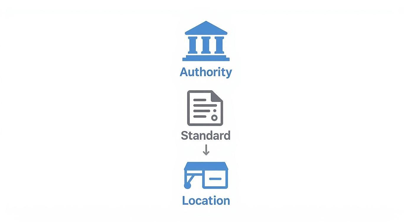
This hierarchy of protection is a perfect example of how electrical codes and standards translate from paper to the real world, flowing from the highest authority down to a specific piece of equipment.
This visual just hammers it home: safety rules start with a governing body (like the NEC), get baked into a standard (like UL 943), and are then applied right where they're needed, like that outlet in your kitchen.
The Challenge of Nuisance Tripping
One of the biggest headaches in this field is nuisance tripping. This is when a protective device trips out during perfectly normal operation, not because of a real hazard. It's a constant battle, especially in plants filled with equipment like variable frequency drives (VFDs) or servo amplifiers, which generate a ton of electrical "noise" that can fool a sensitive GFCI into thinking there's a problem.
Tempting as it may be, you can't just disable the protection. Instead, good engineers use a mix of strategies:
Use GFPE Devices: These equipment protectors are less sensitive than their personnel-protecting cousins (GFCIs) and often have adjustable time delays, letting them ignore momentary current blips.
Proper Shielding and Grounding: Simply making sure motor cables and control wiring are correctly shielded and grounded can slash electrical noise and solve a lot of problems.
Isolation Transformers: For really sensitive gear, an isolation transformer can create a clean, dedicated power source, completely separating it from the noise on the main system.
Wrestling these issues requires a deep, hands-on understanding of both the equipment and the electrical environment it lives in.
Selective coordination is the art of making sure the breaker closest to a problem opens first. It’s what stops a small, localized issue from turning into a full-blown, plant-wide outage.
Achieving Selective Coordination
Picture this: a small fault happens in one machine out on the factory floor. In a poorly designed system, that tiny hiccup could trip the main breaker for the entire building, bringing everything to a screeching halt. That’s exactly what selective coordination is designed to prevent. It’s an absolutely critical concept for building a reliable ground fault protection system.
The idea is to create a clear pecking order. The device right next to the fault—say, a small branch-circuit breaker—should trip first and fastest. The next breaker upstream, maybe for a larger feeder, is set with a slightly longer time delay. The main breaker? It has the longest delay of all. This tiered system guarantees that only the affected part of the circuit goes offline.
Pulling this off takes careful engineering and a lot of math to get the trip settings of every device just right. But when it's done correctly, you get the best of both worlds: enhanced safety and maximum uptime. For anyone diving into this process, getting a solid grasp of industrial control panel design is invaluable, as it shows you exactly how these protection schemes are woven into the heart of a control system.
The Long Road to Modern Electrical Safety
That little GFCI outlet in your kitchen, the one with the "TEST" and "RESET" buttons, is the result of more than a century of hard-won innovation. The idea of ground fault protection wasn’t a single brilliant idea that appeared overnight. Instead, it was painstakingly built, piece by piece, by engineers grappling with the new and often deadly challenges of a world powered by electricity.
To really get a feel for how far we've come, you have to go back to the turn of the 20th century. As power grids began stretching across the country, engineers ran into a huge problem: how do you shut down one faulty power line without plunging an entire city into darkness? The first attempts were clumsy, often just simple fuses that couldn't tell the difference between a momentary overload and a catastrophic fault.
The First Breakthroughs in Protective Relays
The first real leaps forward happened out of necessity, driven by the need to protect the massive new power plants of the era. One of the earliest game-changing moments was around 1899 at the Niagara power plants. Engineers there devised a clever way to achieve selective line protection for their 11 kV network, using a directional element to create a reverse current protection scheme. Many see this as the true birth of selective protection, a concept that's still at the heart of electrical safety today. You can dive deeper into the history of protection engineering and how these ideas came to be.
Right on the heels of that innovation came another critical development. In 1908, an engineer named Nicholson came up with the summation current circuit for detecting earth faults. It was a brilliantly simple concept: measure the current going out and compare it to the current coming back. If they don't match, you have a leak. This fundamental principle is still the basis for every GFCI and ground fault relay in use today.
The core idea behind modern ground fault protection is over 100 years old. It's based on a simple principle: what goes out must come back. If it doesn't, the electricity has leaked somewhere it shouldn't, and the circuit must be shut down instantly.
From Protecting the Grid to Protecting People
For decades, this kind of technology was strictly the domain of big utilities and massive industrial sites. The relays were huge, clunky mechanical devices—far too complex and expensive for the average home. The focus finally shifted toward personal safety in the 1950s and 60s, as a growing number of electrocutions were linked to faulty consumer appliances.
This is when engineers started playing with solid-state electronics to shrink the technology down and make it affordable. Professor Charles Dalziel of UC Berkeley, a pioneer in understanding how electricity affects the human body, was a key figure here. He developed a transistorized relay that would become the prototype for the modern Ground-Fault Circuit Interrupter (GFCI).
His work was the final piece of the puzzle. It proved you could build a device sensitive enough to detect the tiny, lethal currents that can stop a human heart, yet tough enough for daily use in a home. That breakthrough opened the door for the NEC to start requiring GFCIs in kitchens, bathrooms, and outdoor areas—a change that has saved countless lives and fundamentally reshaped our relationship with electricity.
Testing and Troubleshooting Your Protection System
A ground fault protection device is a lot like a silent guardian; you really only know it’s working when it suddenly springs into action. But how can you be sure it will actually do its job when the time comes? The only way is through regular, methodical testing and having a clear game plan for when things go wrong.
Putting a protection system in place is just the first step. The real work—verification, commissioning, and routine maintenance—is what turns a piece of hardware into a safety shield you can actually rely on. These procedures aren't just best practices; they're non-negotiable for keeping your electrical environment safe and running.
Essential Testing Procedures for Every System
Making sure your ground fault protection is ready to go is a simple but vital habit. For the GFCIs in your home or office, it's a quick monthly check.
Push the Button: Press the "TEST" button on the GFCI outlet or breaker. You should hear a solid click as it cuts the power.
Double-Check: Plug in a lamp or phone charger to make sure the outlet is truly dead. No light, no power.
Bring it Back: Press the "RESET" button. The power should pop back on, and your test device should light up again.
For bigger industrial systems with ground-fault relays, the process is a bit more involved and is usually part of a scheduled maintenance program. This often means bringing in specialized gear to inject a simulated fault current, making sure the relay logic and breaker trip mechanisms work exactly as they were designed.
An untested protection device is just a hopeful assumption. Regular verification turns that assumption into a documented certainty, ensuring your safety net is ready to perform when a real fault occurs.
Diagnosing and Solving Nuisance Tripping
One of the biggest headaches you'll run into is nuisance tripping—when a GFCI or relay trips for no obvious reason. This can bring work to a screeching halt and make you lose faith in your system. The trick is to systematically hunt down the root cause instead of just mashing the reset button and hoping for the best.
Troubleshooting Steps for Nuisance Tripping:
Step 1: Isolate the Circuit: Unplug everything. If the GFCI resets and holds, you know the problem is with one of your devices, not the wiring itself.
Step 2: Find the Culprit: Start plugging things back in, one by one. The device that makes it trip is your source. Old motors, failing heating elements, or even a little moisture in an appliance can create tiny current leaks that a sensitive GFCI will pick up on.
Step 3: Inspect the Wiring: If the GFCI trips with nothing plugged in, the problem is likely in the wiring. Look for moisture in an outdoor junction box, worn-out insulation, or even a loose connection.
In industrial settings, things like servo amplifiers can generate enough electrical noise to cause nuisance trips, leading to jerky motor behavior or sudden shutdowns. In these cases, checking for properly shielded cables and a solid single-point grounding scheme often solves the problem without sacrificing safety.
Remember, a persistent trip isn't an annoyance—it's a signal that something needs a closer look.
Common Questions About Ground Fault Protection
Even with a solid understanding of the basics, a few common questions always seem to pop up when we're talking about ground fault protection. Let's tackle them head-on, because getting these details right is what makes these systems work in the real world.
What’s the Difference Between a Circuit Breaker and a GFCI?
Think of it this way: a standard circuit breaker is like a security guard for your building’s electrical system. Its job is to watch for huge problems, like a massive overload or a dead short, that could cause a fire. When it sees way too much current trying to flow, it shuts everything down.
A GFCI, on the other hand, is a personal bodyguard for you. It’s not looking for system-wide overloads. Instead, it’s watching for tiny, almost undetectable leaks of electricity—the kind that happen when current finds a path through a person. If it senses an imbalance as small as 4-6 milliamperes, it knows something is wrong and cuts the power in an instant.
Why Does My GFCI Outlet Keep Tripping?
We hear this one all the time. It’s often called "nuisance tripping," but it’s rarely a nuisance for no reason. The culprit can be something as simple as moisture getting inside an outdoor outlet box or even just a bit of accumulated dust creating a path for current.
Older appliances, especially those with motors or heating elements, can also develop tiny, harmless current leaks that are still just enough to make a sensitive GFCI do its job.
If you're trying to figure it out, here’s a quick process of elimination:
First, unplug everything from the GFCI circuit and hit the reset button.
If it stays on, start plugging your devices back in, one by one. When it trips, you’ve found the problem appliance.
If it trips immediately with nothing plugged in, the issue is likely in the wiring or the GFCI outlet itself. That's a job for a professional.
A GFCI that keeps tripping isn't just being annoying; it's sending you a signal. It's telling you there's a potential problem that needs attention, whether it's in a faulty appliance or the circuit itself.
Can I Install a GFCI on a Circuit Without a Ground Wire?
Yes, you can, and it's a common safety upgrade recognized by the National Electrical Code for older homes with two-wire circuits. A GFCI works by constantly monitoring the balance between the hot and neutral wires. If there's a difference, it trips—a function that doesn't need a ground wire to work.
There's a catch, though. You are required to label the outlet with a sticker that clearly says "No Equipment Ground" and "GFCI Protected." This lets everyone know that while the outlet offers excellent shock protection, it can't provide the grounding path that some electronics rely on for things like surge protection.
At E & I Sales, we live and breathe this stuff. We specialize in designing and building reliable, code-compliant UL-listed control panels that have exactly the right ground fault protection for your equipment and personnel. If you want to make sure your systems are both safe and efficient, contact us today.
The NEC tap rule is really just a set of common-sense exceptions to a fundamental electrical safety rule. Found in NEC 240.21, it lets you connect a smaller wire—the "tap conductor"—to a much larger circuit without putting a circuit breaker right at the connection point. It’s a solution born from real-world necessity, especially in industrial settings where adding a breaker at the tap is often completely impractical.
So, Why Do We Even Need a Tap Rule?
The National Electrical Code is built on one core safety principle: protect a wire from overcurrent right where it gets its power. Simple enough. This usually means every time you go from a big wire to a smaller one, you need a fuse or breaker in between. But what happens when that's just not possible?
Picture a massive, high-amperage busway running along the ceiling of a packaging plant. You need to drop power down to a single control panel or motor starter on the floor. Sticking a bulky overcurrent device way up on the busway for that one small connection would be a nightmare to install and maintain.
This is where the tap rule comes in. It’s not a free-for-all loophole; it’s a carefully engineered set of guidelines that acknowledges a short, protected run of wire is extremely unlikely to fail. Think of it less like breaking the rules and more like a controlled, pre-approved detour.
The logic is sound. The NEC allows this exception because it builds in several non-negotiable safety layers:
Keep It Short: The length of the unprotected tap wire is strictly limited—usually to 10 feet or 25 feet—to drastically reduce the exposure to physical damage or a potential fault.
Size It Right: The tap wire can't be just any size. It has to be beefy enough to handle the potential fault current until the downstream breaker (the one at the end of the tap) has a chance to trip.
Protect It Physically: Tap conductors can't just be left dangling. They absolutely must be installed inside a raceway, like a rigid metal conduit, to shield them from getting crushed, cut, or damaged.
At the end of the day, understanding the tap rule is all about knowing how to safely tie into an existing electrical system. While it's a specific electrical concept, you can see similar logic in other fields—for a different perspective on making live connections, you might find it interesting to read about the general concept of hot tapping in pipeline repair.
By sticking to these precise guidelines, we can build electrical systems that are both highly functional for the plant floor and fully compliant with the highest safety standards, preventing fires and protecting our equipment.
NEC Feeder Tap Rules at a Glance
To make sense of the different scenarios, it helps to see the most common feeder tap rules laid out side-by-side. This table gives you a quick snapshot of the length limits and core requirements for each.
Tap Rule
Maximum Length
Minimum Ampacity Requirement
Termination Device
10-Foot Tap Rule
10 feet
Must be at least the ampacity of the load served and the rating of the termination device.
Must terminate in a single circuit breaker, a set of fuses, or an approved overcurrent protective device.
25-Foot Tap Rule
25 feet
Must be at least 1/3 the ampacity of the feeder's overcurrent device.
Must terminate in a single circuit breaker or a set of fuses rated no more than the tap conductor's ampacity.
Outside Tap Rule
Unlimited
Sized for the calculated load, following standard conductor sizing rules.
Must terminate in a readily accessible overcurrent device located near the point of entrance.
Transformer Taps
Per NEC 240.21(C)
Varies based on primary/secondary protection and specific rule subsection.
Typically terminates in an overcurrent device on the secondary side.
Think of this table as your cheat sheet. While the full code text has all the nuances, these are the big-picture requirements you'll encounter most often when designing or inspecting an installation.
Getting to Know the Three Main Feeder Tap Rules
While the general idea of the NEC tap rule gives us a starting point, its real-world use is all about a few specific, common-sense exceptions. These rules aren’t interchangeable—not by a long shot. Each one is built for a different scenario, with its own strict recipe for length, conductor size, and how you terminate the run. Figuring out which rule fits your job is the first step to a safe, compliant installation.
At its core, the reason we even have these rules is simple: electrical protection. This flowchart really boils it down to the first question you should ask: if a conductor has overcurrent protection right where it starts, it's a standard, protected circuit. If not, you’re officially in tap rule territory.
This visual guide cuts through the noise. The second you see there's no Overcurrent Protection Device (OCPD) at the tap point, your only path forward is to follow one of the specific NEC tap rules to the letter.
The 10-Foot Tap Rule
This is the one you’ll see most often, which is why it’s often just called the "short tap." The rule, found in NEC 240.21(B)(1), is perfect for those tight spots where equipment is right next to the feeder. Think tapping a busway to feed a disconnect directly below it, or powering a small control transformer inside a larger panel.
The logic here is pretty straightforward: a very short run of wire, completely enclosed in a protective raceway, has an incredibly low chance of getting damaged and causing a problem. But that flexibility comes with some very firm conditions.
To use the 10-foot tap rule, you have to check every single one of these boxes:
Length: The tap conductors can't be a hair over 10 feet long.
Ampacity: The wire's ampacity must be at least the calculated load it serves and be equal to or greater than the rating of the device it lands on.
Protection: The conductors have to be installed in a raceway to shield them from physical damage.
Termination: This is the big one. The tap conductors must terminate in a single circuit breaker or a single set of fuses.
Key Takeaway: The 10-foot rule is a strict exception that absolutely does not let you feed a lighting panel or a distribution panelboard directly. That requirement for termination on a single overcurrent device is non-negotiable.
The 25-Foot Tap Rule
When you need to cover a bit more ground, the 25-foot tap rule in NEC 240.21(B)(2) gives you more length. But in exchange, it demands a beefier conductor to make up for the added risk. You’ll see this rule a lot in industrial plants for hooking up machinery that isn't parked right next to the main power source.
Because the wire run is longer, the NEC forces you to upsize the conductor. This ensures it can handle a potential fault current from the main feeder's breaker without melting down before the breaker can trip.
Here’s the checklist for this rule:
Length: The total length of the tap conductor must not exceed 25 feet.
Ampacity: The tap conductor must have an ampacity of at least one-third (1/3) of the rating of the breaker or fuse protecting the main feeder.
Protection: Just like the 10-foot rule, these wires must be enclosed in a raceway. No exceptions.
Termination: The tap has to terminate in a single circuit breaker or set of fuses rated no higher than the tap conductor's ampacity.
That "one-third" sizing rule is a critical safety factor. For instance, if you're tapping a feeder that's protected by a 600A breaker, your 25-foot tap conductors need an ampacity of at least 200A (600A / 3).
The Over 25-Foot Tap Rule for High-Bay Buildings
This one is less common but absolutely essential in the right setting. The "Over 25-Foot" rule in NEC 240.21(B)(4) is the go-to for high-bay manufacturing facilities and other industrial buildings with soaring ceilings. It allows for taps up to a whopping 100 feet long, but it’s extremely restrictive and only applies under very specific circumstances.
This rule was written to solve a real-world problem: how do you safely tap an overhead busway in a building with a ceiling over 35 feet high and get power down to equipment on the floor?
The conditions are, as you'd expect, very stringent:
Building Type: This is only allowed in high-bay manufacturing buildings where the ceiling height is over 35 feet.
Length Limit: The total length of the tap can't exceed 100 feet.
Installation: The conductors must be installed and maintained only by qualified persons.
Ampacity: Same as the 25-foot rule, the ampacity has to be at least 1/3 of the feeder's overcurrent protection rating.
Conductor Type: The tap conductors can't be smaller than 6 AWG copper or 4 AWG aluminum.
Physical Protection: They must be in a raceway and can't be run where they could get damaged.
This specialized NEC tap rule is a perfect example of the code evolving to meet the needs of modern industrial environments, offering an engineered, safe solution for a unique challenge.
The Golden Rules for All Tap Conductors
Getting the math right on the 10-foot or 25-foot rules is only half the battle. Before you even think about lengths and ampacities, the NEC lays down a few non-negotiable ground rules. These principles apply to every single tap installation, no matter what.
Think of them as the fundamental safety backstops. They’re designed to prevent dangerous setups and are often the first things an inspector will look for. Getting these wrong is a surefire way to get a red tag, because they cut right to the core of electrical safety.
The No Daisy-Chaining Rule
Here’s the big one, and it's a mistake we see all too often: a tap conductor can never be tapped again. Seriously, don't do it. A tap is supposed to be a short, protected bridge from a high-capacity feeder to a single point of protection.
When you tap that tap, you create a daisy chain of unprotected wiring. This "tap on a tap" effectively creates a new branch circuit with no properly sized overcurrent protection device (OCPD) at its source, making it a massive fire hazard. The NEC is black and white on this: the tap's journey ends at one—and only one—protective device.
Your Taps Need Armor (Mandatory Physical Protection)
By their very nature, tap conductors aren’t protected by a breaker or fuse right where they begin. This leaves them incredibly vulnerable. If something damages the insulation and the wire shorts out, the only thing that can stop the runaway current is the massive upstream breaker on the main feeder. That can let a huge amount of fault current flow, which is a recipe for disaster.
To counter this risk, the NEC demands that all tap conductors be installed inside a raceway or a suitable enclosure. This isn't just a suggestion.
Enclosed and Shielded: The wires must be protected from physical harm along their entire run. This typically means putting them in rigid metal conduit, EMT, or another approved raceway.
No Exposed Wires: You can't just leave tap conductors hanging in the open, even for a few inches. The raceway is their suit of armor, guarding against cuts, crushing, and abrasion that could lead to a catastrophic failure.
One Tap, One Destination
Another universal rule is that every feeder tap must terminate at a single overcurrent protective device (OCPD). This means the tap has to land on the line-side lugs of a single circuit breaker or a single set of fuses.
Pay close attention to this: You cannot run a tap conductor straight to the main lugs of a panelboard and then feed multiple smaller breakers from there. The tap must feed a single main breaker that, in turn, protects the entire panelboard. This creates one clear point of disconnect for everything downstream.
Knowing what a proper OCPD looks like is key. If you want to see how these devices act as the final gatekeeper for a tap installation, you can learn more about an ABB circuit breaker and its role in the system. This single-device rule is a cornerstone of tap safety, preventing a single tap from spawning multiple, unprotected circuits.
Alright, let's get this done. The theory behind the NEC tap rule is one thing, but making it work on a noisy, chaotic plant floor is a completely different ballgame. This is where the codebook hits the concrete.
Let’s walk through two super common scenarios you’ll run into, breaking them down to show how these rules translate into safe, compliant, and practical installations.
These examples aren't just academic—they're the real-world calculations and gut checks you'll be making on the job.
Example 1: The 25-Foot Tap for a New Conveyor
Picture this: you're installing a new conveyor system in a packaging facility. It needs a 150A feed, and the most convenient power source is a 600A busway running along the ceiling, about 20 feet from the machine. Tapping right into the busway with a breaker is a non-starter. This is a textbook case for the 25-foot tap rule.
The plan is to tap the 600A busway and run conductors down to a 150A fused disconnect mounted on the wall right next to the new machine.
Here's how we'd tackle it, step-by-step:
Pick Your Rule: The total run is 20 feet. That's more than 10 feet but less than 25 feet, so we know we're working with the 25-foot tap rule found in NEC 240.21(B)(2).
Size the Conductor: This is the most critical calculation. The rule mandates that the tap conductor's ampacity must be at least one-third (1/3) the rating of the feeder's protection—in this case, the 600A busway. The math is straightforward: 600A / 3 = 200A. Our tap conductors need to be rated for at least 200A.
Grab the Right Wire: Time to hit the ampacity tables. Looking at Table 310.16 (using 75°C terminations), we find that a 3/0 AWG THHN copper conductor is rated for exactly 200A. Perfect. It meets our minimum requirement.
Check the Termination: The tap has to end at a single overcurrent protective device (OCPD). Our 150A fused disconnect fits the bill. Just as important, the 150A rating of the disconnect is less than the 200A ampacity of our 3/0 AWG tap wire. That's a key safety check you can't skip.
Protect the Run: That entire 20-foot run of 3/0 wire can't just be hanging out. It absolutely must be installed inside a raceway, like rigid metal conduit, to shield it from physical damage.
Follow those steps, and you've got a rock-solid, fully compliant installation. The conductors are sized right, physically protected, and terminate correctly.
Example 2: The 10-Foot Tap in a Control Panel
Now for a smaller, more common job inside an existing control cabinet. We're adding a new PLC that needs a dedicated 120V source, so we have to drop in a small control power transformer (CPT). The panel's main bus is fed from a 225A breaker.
The CPT will be mounted just a couple of feet from the bus, all within the same enclosure. This is the ideal spot to use the 10-foot tap rule, NEC 240.21(B)(1).
A Quick Note on Enclosures: The NEC treats the inside of a control panel or wireway as a protected space. If you need a refresher on picking the right box for the job, you can explore the different electrical boxes types and what they're designed for.
Here’s the breakdown for the 10-foot rule:
Confirm the Rule: The CPT is 3 feet from the bus—well under the 10-foot limit. We're good to go.
Check Ampacity: The 10-foot rule is a bit different. The tap conductor must be rated for the greater of the load it serves or the rating of the device it terminates into.
Pick Your Protection: We’ll protect the primary side of the CPT with a small, fused switch rated for 2A. This means our tap conductor needs an ampacity of at least 2A. A simple 14 AWG THHN copper wire, rated for 15A, is more than enough.
Verify the Termination: The tap conductors run straight from the main bus to the line side of that 2A fused switch. That single set of fuses satisfies the rule’s requirement for terminating in a single OCPD.
Ensure Protection: Since the entire tap is inside the metal control cabinet, the conductors are already considered protected from physical damage. No extra conduit is needed.
This is a classic example of why the 10-foot NEC tap rule is so useful. It lets you make small, essential power connections inside a panel without burning a valuable breaker slot for a tiny load. It's an efficient, safe solution you’ll see in control panels every single day.
Specialized Tap Rules for Transformers and Motors
The standard feeder tap rules handle a lot of common situations, but once you step onto the plant floor, things get more complicated. Industrial settings are packed with specialized equipment—transformers and motors, specifically—that have their own unique electrical personalities.
The National Electrical Code gets this. That's why it provides a distinct set of tap rules just for these applications. They aren’t completely new rules, but rather smarter, more specific versions of the feeder tap rules, adapted for the realities of inductive loads.
Getting these specialized rules right is non-negotiable for any plant engineer or packager. If you mistakenly apply a standard feeder rule to a transformer secondary or a motor circuit, you're asking for trouble. You could end up with improper protection, constant nuisance tripping, or even a catastrophic failure. The Code lays out these separate guidelines to account for things like massive transformer inrush current and the brutal startup demands of a motor.
Transformer Secondary Tap Rules
Transformers are the backbone of any plant's power distribution, stepping voltage up or down wherever you need it. The conductors coming off the secondary side of a transformer play by their own set of rules, which you'll find in NEC 240.21(C). It helps to think of a transformer secondary as creating a "separately derived system." It's essentially a new starting point for power, and your overcurrent protection has to reflect that.
The rules for transformer secondaries will feel familiar if you know the feeder tap rules, but the details are what matter. They allow for very specific lengths of unprotected conductor on the secondary side before an overcurrent protective device (OCPD) is required.
Here are the two scenarios you'll run into 99% of the time:
The 10-Foot Secondary Rule: Just like the feeder tap rule, you can have up to 10 feet of unprotected secondary conductors. The key is that they must be properly sized for the load and must terminate in a single OCPD. You see this all the time when a disconnect is mounted right next to the transformer.
The 25-Foot Secondary Rule: This rule gives you more breathing room, allowing up to 25 feet of secondary conductor. But there are strings attached: the conductors have to be sized with an ampacity of at least 1/3 of the transformer secondary rating, be physically protected inside a raceway, and terminate in a single OCPD.
The Big Picture: The whole point of these rules is to give you a practical way to get power from the transformer’s secondary lugs to the first line of defense—the breaker or fuse. The strict length limits and physical protection requirements make the risk of a fault on that short, unprotected run incredibly low.
Navigating Motor Circuit Tap Rules
This is where things can get really tricky. Motor circuits force you to juggle two different parts of the NEC: Article 240 (Overcurrent Protection) and Article 430 (Motors, Motor Circuits, and Controllers). This crossover is a massive source of confusion and failed inspections.
When you tap a feeder to supply a motor, you're still following the basic principles of the feeder tap rule. The difference is that the final termination requirements are dictated by the unique needs of the motor. Your tap has to end at the motor’s branch-circuit protective device, which is usually a fused disconnect or a special motor circuit protector inside a motor control center (MCC) bucket.
Think about tapping a busway to feed an individual motor starter. It requires careful coordination. The tap conductors themselves must be sized based on the appropriate NEC tap rule (like the 25-foot rule). However, the fuses or breaker at the end of that tap must be sized according to Article 430 to handle the motor's huge inrush current on startup.
This is a critical distinction. It ensures the motor can roar to life without instantly tripping the breaker, while still giving you the short-circuit protection you need. To make sure your designs are bulletproof, you can take a deeper dive into the specific requirements for the protection of motors in our detailed guide. Mastering these specialized rules is essential for keeping your most vital plant assets running safely and efficiently.
Common Tap Rule Violations and How to Avoid Them
Knowing the NEC tap rule is one thing. Actually avoiding the common slip-ups that get you a red tag from an inspector? That’s what really counts on the job site. Even seasoned installers can make simple mistakes that compromise safety and force expensive rework. Getting these rules right is a huge part of avoiding the common electrical problems home inspectors uncover and just doing a safe, professional job.
The best way to pass inspection is to think like an inspector. These violations aren't just about checking a box in the codebook; they represent very real fire and shock hazards that put people and equipment in jeopardy.
Mistake 1: Tapping a Tap
This is one of the most dangerous and, unfortunately, frequent violations I see. It’s simple: a tap conductor is meant to go from a protected feeder to a single overcurrent protective device (OCPD). Tapping that conductor again creates a daisy chain of unprotected wiring.
Think about it. You’re essentially creating a brand-new branch circuit that has no properly sized protection at its origin. If a fault happens on that second tap, the only thing that can clear it is the massive upstream breaker—which will happily let a dangerous amount of current flow long enough to start a fire.
The Fix: Treat every tap conductor like a one-way street. Its journey has to end at a single breaker or a set of fuses. If you need to power another piece of equipment, you have to go back to the original feeder or, better yet, install a small distribution panel fed from the first tap’s OCPD.
Mistake 2: Exceeding Length Limits
Those length limits—10 feet and 25 feet for the most common rules—aren't suggestions. They are hard-and-fast limits based on an accepted level of risk. A classic mistake is grabbing a tape measure and getting the straight-line distance, completely forgetting about the actual conductor length, which includes all the bends and turns inside the conduit.
Stretching that length increases the conductor's exposure to physical damage and voltage drop. More critically, it extends the run of wire that isn't immediately protected by a right-sized OCPD, which is the exact risk the tap rule is designed to manage.
Mistake 3: Botching the Ampacity Calculation
Getting the ampacity of a tap conductor wrong is another critical error. It usually happens in one of two ways:
For the 25-foot rule, the tap conductor’s ampacity must be at least one-third of the feeder’s OCPD rating. It’s based on the breaker, not the feeder conductor's ampacity. Using the wire size as your reference is a fast track to an undersized tap.
For the 10-foot rule, the tap has to be sized for the load it serves and the rating of the device it terminates on. In the rush of a job, this sometimes gets overlooked.
An undersized tap can't handle a fault. During a short circuit, it can overheat and melt long before that big upstream breaker even thinks about tripping. The entire protection scheme becomes useless.
To keep these common headaches off your punch list, run through a simple mental checklist before you pull any wire:
Check the Source: Are you tapping a feeder or another tap? Make sure it's the feeder.
Measure the Real Length: Pull a string or use a fish tape to measure the actual path the wire will take.
Calculate Ampacity Right: Always base that 1/3 calculation on the feeder’s breaker, not its wire gauge.
Confirm the Landing Spot: Does the tap land on a single OCPD? It has to.
Look at Physical Protection: Is the entire tap run buttoned up in a raceway? No exceptions.
Frequently Asked Questions About the NEC Tap Rule
Even when you feel you've got a handle on the rules, weird situations always pop up on the job site. Let's walk through some of the most common questions about the NEC tap rule to bridge that gap between what the codebook says and what you actually see in the field.
Can I Feed a Small Subpanel with the 10-Foot Tap Rule?
This is probably the number one mistake we see people make, and the short answer is no.
The language in NEC 240.21(B)(1) couldn't be clearer: tap conductors have to terminate in a single circuit breaker or a single set of fuses. A subpanel, by definition, is a collection of multiple breakers, so landing your tap conductors directly on its main lugs is a serious violation.
Think of it this way: the tap is an intentional, limited exception to the rule. The only way the code allows it is if that unprotected run ends immediately at a single, dedicated shut-off. The correct way to do this is to run your tap conductors to one main breaker, which then protects the entire subpanel downstream.
For the 25-Foot Rule, Do I Size the Tap Wire to the Feeder Wire or the Breaker?
Another absolutely critical point. The one-third (1/3) ampacity requirement for the 25-foot tap is based on the rating of the overcurrent protective device (OCPD) that's protecting the main feeder. It has nothing to do with the size or ampacity of the feeder wires themselves.
For example, if you have a feeder protected by a 400A breaker, your tap conductors must have an ampacity of at least 133A (400A / 3). This is all about ensuring the smaller tap wire can survive a major fault long enough for that big upstream breaker to do its job and trip.
Are Tap Rules Common in Residential Wiring?
Not really. While the NEC is the law of the land for all electrical work, you'll almost exclusively run into tap rule scenarios in commercial and industrial settings.
Residential systems are just built on a different scale. Circuits are smaller, simpler, and almost always run directly from a dedicated breaker back at the main panel. The massive feeders, busways, and distribution switchboards that make the NEC tap rule a necessity are just not part of a typical home's construction.
At E & I Sales, we live and breathe this stuff. Our job is translating complex code into industrial solutions that are practical, reliable, and safe. Whether you need a custom UL-listed control panel or just some expert advice on a tricky motor control setup, our team has the hands-on experience to get your project done right. See how we can help with your next installation at https://eandisales.com.
Walk down any aisle in an electrical supply house, and you'll see a dizzying array of electrical boxes. They come in all shapes and sizes, from simple plastic junction boxes meant for tucking away wire splices to heavy-duty steel device boxes built to hold switches and outlets securely for decades.
But what do they all do? At their core, their job is to safely wrap up electrical connections. They’re the first line of defense, protecting wires from getting damaged and, just as importantly, protecting us from accidental contact that could lead to shocks or fires.
The Hidden Backbone of Safe Electrical Wiring
Think of electrical boxes as the silent, essential hubs of your building's entire nervous system. They’re not just simple containers; they're the critical junctions where the flow of electricity is safely managed and directed. You'll find them in every single electrical system, from the light switch in your living room to a massive industrial motor control center.
Every box, no matter its shape or material, serves three fundamental roles. It's this trifecta of duties that ensures a system is not only functional but also reliable and up to code.
The Critical Roles of an Electrical Box
Let's break down what these enclosures are really doing behind the scenes:
Containment and Protection: First and foremost, a box houses wire connections. If a connection ever arcs or sparks—and it can happen—the box contains it. This simple act prevents those sparks from reaching flammable materials like wood studs or insulation, which is a massive factor in fire prevention.
Organization and Accessibility: Wires need a clean, logical place to terminate or be spliced. Boxes provide that structure. For any electrician coming in later to troubleshoot a problem or add a new circuit, this organization is a lifesaver. It makes the job faster, safer, and a whole lot less frustrating.
Safety and Grounding: This is a big one. When you're working with metal boxes and metal conduit, the box itself becomes a key part of the grounding system. If a hot wire somehow makes contact with the metal box, this ground path provides a direct route for the fault current, instantly tripping the circuit breaker and shutting down the danger.
An improperly installed or undersized electrical box is a ticking time bomb. When you cram too many wires into a small space, you get heat buildup. That heat breaks down wire insulation over time, creating the perfect recipe for a short circuit and an electrical fire.
Quick Guide to Common Electrical Box Types and Uses
To get a clearer picture, it helps to see how different boxes are used in the real world. This table gives a quick rundown of the most common types you'll encounter and where they typically fit in.
Box Type
Primary Use
Common Material
Junction Box
Enclosing wire splices and connections
Steel, PVC, Fiberglass
Switch/Device Box
Mounting switches, outlets, and dimmers
Steel, PVC
Octagon/Round Box
Mounting ceiling lights and smoke detectors
Steel, PVC
Conduit Body
Providing pull points and turns in conduit runs
Aluminum, Steel
Weatherproof Box
Outdoor outlets, switches, and lighting
Die-cast Aluminum
This is just a starting point, of course. The specific needs of a residential, commercial, or heavy industrial project will dictate the best choice, but knowing the basics is the first step.
Ensuring a Safe Work Environment
Before you even think about touching a wire, your first priority is always safety. No exceptions. Shut off the power at the main circuit breaker that controls the circuit you're working on. Then, double-check that the power is actually off.
You can't trust that a switch is off just because it's in the down position. Always verify with a tester. Tools like non-contact voltage detectors are perfect for this—they'll tell you instantly if there's any live current present without you having to touch a single wire.
This guide will be your roadmap to navigating the world of electrical boxes. We’ll cover everything from the standard boxes in your walls to the rugged, specialized enclosures that keep critical industrial systems running, giving you the practical knowledge you need for your next project.
Diving Into the Most Common Electrical Boxes for Any Job
Once you get past the high-level theory, the world of electrical boxes opens up into a whole cast of specialized players, each built for a very specific role. Think of it like a mechanic's toolbox; you don't use a sledgehammer to tighten a small bolt. In the same way, an electrician picks the right box for the job to make sure every connection, switch, and fixture is housed correctly and safely.
Getting to know these common workhorses is the first step to making smart, code-compliant choices on any project. Each box has a specific purpose, whether it's just protecting a few spliced wires or providing a rock-solid anchor for a heavy ceiling fan.
This diagram breaks down the fundamental jobs of any electrical box, showing how it provides containment, organization, and safety all at once.
As you can see, a box isn't just a simple container. It's an active safety component that provides structure, protection, and a hub for keeping everything up to code.
Junction Boxes: The Unsung Heroes
The junction box is probably the most essential type of electrical box out there. Its job is straightforward but absolutely critical: to house and protect wire splices. Any time you need to connect wires together—whether to extend a circuit, branch off in a new direction, or join different types of cable—those connections have to be made inside a junction box.
Think of it as a secure meeting point for electrical conductors. The wires come in, get safely connected with wire nuts, and the box is sealed up with a blank cover. This simple setup prevents anyone from accidentally touching a live wire, keeps dust and debris away from the delicate connections, and even contains potential sparks. The National Electrical Code (NEC) is very clear that every splice must remain accessible, which means you can never bury a junction box behind drywall or plaster.
Device Boxes: The Interactive Hub
Next up are device boxes, which you probably know better as switch boxes. These are the rectangular boxes you see every day holding light switches, dimmers, and electrical outlets. They're designed specifically to mount these devices securely, with threaded holes for screws and enough internal space for both the device and all the wiring behind it.
Device boxes come in a few common configurations, often described by "gangs."
Single-Gang Box: The standard size, built to hold just one device, like a single light switch or outlet.
2-Gang Box (or Multi-Gang): These are wider boxes made to hold two or more devices right next to each other—perfect for a switch and an outlet combo or a bank of light switches.
4-Square Box: A versatile 4×4 inch metal box that can act as a large junction box or be fitted with a special cover (called a mud ring) to mount one or two devices.
One of the biggest mistakes people make is cramming too many wires into a device box. You always have to calculate your "box fill" to make sure you have enough cubic-inch capacity. Overcrowding can lead to dangerous heat buildup and is a major fire hazard.
Octagon and Round Boxes: The Overhead Mounts
Look up at your ceiling, and you're probably looking at the handiwork of an octagon box or its sibling, the round box. These uniquely shaped enclosures are the go-to choice for mounting ceiling fixtures like lights, smoke detectors, and ceiling fans. Their shape gives you plenty of angles to secure the fixture's mounting bracket.
While a standard octagon box works great for a lightweight light fixture, you need something much tougher for a ceiling fan or a heavy chandelier. For those jobs, you must use a box that is specifically fan-rated. These are usually made of steel and are designed to mount directly to a ceiling joist or a heavy-duty brace, giving them the strength to handle the weight and dynamic forces of a spinning fan.
You'll also find a super-shallow version called a "pancake box." These are thin, round boxes used for light fixtures when there's no room inside the wall or ceiling for a standard box. They provide just enough space for the connections while sitting almost flush against the surface. Each of these box types has a clear-cut role, making your selection process a lot easier once you know what you're trying to accomplish.
Choosing the Right Materials and Construction
Ever wondered why some electrical boxes are metal and others are plastic? It’s not just about what’s cheapest. The material you choose is a critical decision based on the job site, the kind of wire you're running, and the safety codes you have to meet.
Think of it like picking the right gear for the job. What works perfectly in a wood-framed house would be a total liability in an industrial plant. Getting a handle on the differences between metallic and non-metallic boxes is the first step toward a safe, solid, and up-to-code electrical system.
Metallic Boxes: Steel and Aluminum
For as long as anyone can remember, metal boxes have been the go-to for commercial and industrial work. There's a good reason for that. Their natural toughness and ability to conduct electricity make them non-negotiable for certain installations.
Steel boxes are the undisputed heavyweights. Their biggest advantage is brute strength and the fact that they don't burn. This rugged build is a must-have in places where a box might take a hit. More importantly, when you're working with metal-sheathed cable (like MC) or running wires through metal conduit, a steel box is a key part of the grounding system. The box itself completes the ground path, which is a massive safety feature.
Aluminum boxes are the lighter-weight cousin to steel, which makes them a bit easier to wrangle. You'll often see them as die-cast conduit bodies or those familiar weatherproof boxes for outdoor outlets, where their built-in resistance to corrosion really shines.
Non-Metallic Boxes: PVC and Fiberglass
Lately, plastic boxes have taken over, especially in residential construction. They're just plain easier and more cost-effective for a lot of jobs.
PVC (Polyvinyl Chloride) boxes are what you'll find in most new homes today. They're cheap, light, and a breeze to install—a quick tap with a screwdriver is all it takes to pop out a knockout. Since PVC doesn't conduct electricity, the box itself doesn't need to be grounded. This makes wiring with standard non-metallic (NM) cable much simpler.
This choice between metal and plastic isn't just a job-site debate; it's big business. The global market for electrical boxes is currently valued at USD 6,992.4 million and is expected to climb to USD 10,682.4 million by 2033. PVC boxes are the clear leader, holding over 59.84% of the market thanks to their low cost and perfect fit for residential wiring.
Fiberglass boxes are a definite upgrade from standard PVC. They're tougher and won't get brittle or flex in extreme hot or cold, making them a great pick for demanding spots like unfinished basements, workshops, or even some light industrial areas where you still want a non-conductive box. When you're dealing with more advanced systems, material selection becomes even more critical, as we cover in our guide to industrial control panel design.
Making the Right Choice for Your Project
So, metal or plastic? The decision really comes down to a few straightforward factors.
Your Wiring Method: This is the golden rule. If you're running wire in metal conduit or using metal-clad cable, you must use a metal box. No exceptions. It's essential for proper grounding. For standard non-metallic (Romex) cable, a plastic box is usually the path of least resistance.
The Environment: Think about where the box will live. Is it going to be exposed to rain or moisture? You'll need a weatherproof box made of PVC, fiberglass, or die-cast aluminum. Is it in a garage or workshop where it might get bumped? A tough steel box is the way to go.
Cost and Labor: On a large residential build, the savings from using inexpensive PVC boxes and the speed of installing them really add up. But for a commercial job, the priority shifts to long-term durability, making steel the smarter investment, even if it takes a bit longer to install.
Going Beyond the Basics: A Look at Specialized Electrical Enclosures
While the standard junction boxes and device boxes are the bread and butter of most wiring jobs, some situations call for something much tougher. When you’re taking a project outdoors, running conduit underground, or trying to wrangle massive conductors, you need an enclosure that was built for the job.
Think of it like the difference between your daily driver and a purpose-built off-road truck. Both will get you from A to B, but only one is engineered to handle mud, rough terrain, and brutal weather. Specialized electrical enclosures are the heavy-duty off-roaders of the electrical world, built to protect critical connections where ordinary boxes would quickly fail.
Weatherproof Boxes: Your First Line of Defense Against the Elements
Any electrical connection outside is in a constant fight with moisture, dust, and wild temperature swings. That's where weatherproof boxes step in. These aren't just regular boxes with a slightly better cover; they're complete systems engineered from the ground up to create an impenetrable seal against the environment.
Usually made from die-cast aluminum or heavy-duty, non-corrosive PVC, their design hinges on a few key features that keep moisture out:
Gasketed Covers: A thick rubber or foam gasket gets compressed between the box and the cover plate, forming a watertight seal that blocks rain, sleet, and snow.
Sealed Hubs: Threaded hubs combined with watertight connectors ensure that any point where conduit enters the box is completely sealed off from moisture.
Durable Construction: The materials themselves are chosen for their ability to resist corrosion and stand up to years of UV exposure without turning brittle.
These features make weatherproof boxes non-negotiable for outdoor outlets, landscape lighting systems, and mounting security cameras, ensuring those connections stay safe and reliable for years to come.
The demand for these rugged solutions is growing fast. The North American market for plastic electrical boxes is projected to grow at a compound annual rate of 6.3% between 2025 and 2030, hitting an estimated USD 10.34 billion. The weatherproof and outdoor segment is a major part of that story, expected to expand at an even faster 6.8% CAGR. This trend highlights a clear shift toward more robust, specialized enclosures, as detailed in this Grand View Research industry analysis.
Pull Boxes: Making Big Conductor Jobs Manageable
On large-scale commercial and industrial jobs, electricians are often tasked with pulling incredibly thick and heavy conductors through hundreds of feet of conduit. Trying to pull those massive cables through multiple bends or over extremely long distances in one go is a recipe for frustration and failure. This is exactly what pull boxes were invented to solve.
At its core, a pull box is a strategically placed junction box that gives you an access point in the middle of a long conduit run. It provides a straight shot for pulling, letting the crew pull one section of cable, neatly coil it inside the box, and then start the next pull from that point. It turns an overwhelming task into a series of smaller, manageable steps.
The National Electrical Code (NEC) actually mandates pull boxes in conduit runs with more than 360 degrees of bends between access points. The code also strictly governs their size to make sure there's enough room to work with the cables without kinking them or damaging their insulation.
Floor Boxes: Discreet Power Where You Need It
In today's open-concept offices, sprawling conference centers, and even high-end custom homes, getting power and data access right where it's needed—without a mess of cords—is a huge design challenge. Floor boxes are the elegant solution, putting outlets and data ports directly into the floor.
These aren't your average boxes. They have to be incredibly tough to withstand constant foot traffic and the weight of heavy furniture. They usually feature a solid metal construction with a heavy-duty cover that sits perfectly flush with the flooring. Many models have recessed connections and pop-up lids, allowing you to plug in cords while keeping the cover mostly closed to minimize tripping hazards.
From industrial control panels to specialized instrument housings, the world of enclosures extends far beyond the common boxes. Here's a quick look at how different types are deployed in demanding settings.
Specialized Electrical Enclosures and Their Industrial Applications
Enclosure Type
Key Feature
Typical NEMA Rating
Industrial Application Example
Hazardous-Location
Explosion-proof or intrinsically safe construction
NEMA 7, 8, 9, 10
Protecting controls in an oil refinery or chemical processing plant.
Conduit Body
Provides access for pulling conductors around bends
NEMA 3R (outdoor)
Connecting rigid conduit runs at a 90-degree angle on an exterior wall.
Meter Box
Houses and secures the utility power meter
NEMA 3R
Standard residential and commercial utility service entrance.
UL-Listed Control Enclosure
Pre-certified to house complex automation systems
NEMA 12, 4, 4X
Housing a PLC, VFDs, and motor starters for an automated conveyor system.
Each of these enclosures solves a specific set of challenges, proving that in the electrical world, having the right box for the job is critical for safety, reliability, and code compliance.
Decoding NEMA Ratings and UL Safety Listings
When you're looking at different types of electrical boxes, you'll see a string of codes and symbols stamped right on them. These aren't just random characters; they're a critical language telling you exactly what that enclosure can handle and how safe it is.
Getting fluent in this language is non-negotiable. It's how you ensure a system is reliable, up to code, and most importantly, safe for everyone involved.
The two names you absolutely need to know are the National Electrical Manufacturers Association (NEMA) and Underwriters Laboratories (UL). Think of NEMA ratings as a toughness score, defining an enclosure's ability to protect what's inside from the outside world. A UL Listing, on the other hand, is the ultimate seal of approval, confirming the product passed a battery of independent safety tests.
Understanding NEMA Ratings
NEMA ratings are a straightforward way to classify how well an enclosure protects its contents from environmental hazards like dust, water, and corrosion. In the industrial world, this is huge. Electrical boxes face everything from fine airborne particles to high-pressure chemical washdowns.
Here’s a quick look at some of the most common ratings you'll run into:
NEMA 1: This is your basic indoor-use rating. It’s designed to keep fingers and tools from touching live parts but doesn't offer much protection against dust or water.
NEMA 3R: Built for the great outdoors, this rating protects against rain, sleet, and ice. You’ll see these everywhere, from utility meter housings to outdoor junction boxes.
NEMA 4X: Now we’re talking serious protection. This rating is watertight against direct hose spray (like a NEMA 4) but adds a critical layer of corrosion resistance. That makes it the go-to choice for punishing environments like wastewater treatment plants, food processing facilities, and marine applications.
NEMA 12: Back indoors, a NEMA 12 enclosure is perfect for the factory floor. It’s built to keep out dripping liquids (non-corrosive ones), circulating dust, and falling dirt.
If you want to go deeper into how these ratings play out in the real world, check out our detailed guide covering NEMA standards. Knowing these inside and out is the key to picking the right box for the job, every time.
The Importance of a UL Listing
While a NEMA rating tells you what an enclosure is designed to do, a UL Listing is your guarantee that it's been independently tested and proven to do it safely. Underwriters Laboratories is a world-renowned safety science organization, and they don't mess around.
A UL Listing is so much more than a sticker—it’s a mark of trust. It means that an electrical box has been rigorously evaluated for potential fire, electric shock, and other hazards. For OEMs and system integrators, specifying UL-listed components is absolutely critical for ensuring the entire system is safe and compliant.
The demand for certified enclosures is exploding. The global market is on track to grow from USD 54.2 billion to a massive USD 87.4 billion by 2035. Junction boxes, which often need specific NEMA and UL ratings, are leading the charge, making up 38.2% of the market thanks to their ability to shield components from dust and moisture.
This growth isn't just a number; it highlights a massive industry-wide shift toward prioritizing safety and reliability, all driven by certifications like those from NEMA and UL.
Your Checklist for Selecting the Right Electrical Box
With so many types of electrical boxes out there, picking the right one can feel a little overwhelming. But it doesn't have to be. By asking yourself a few simple questions, you can cut through the noise and land on the perfect choice for your project.
Think of this as your roadmap. Just follow these questions in order, and you'll find they naturally narrow down your options to the box that’s safe, compliant, and built for the job at hand.
1. What’s This Box Actually Doing?
First things first, what's its purpose?
Are you just making wire connections that need to be safely contained inside a wall? That's a classic job for a junction box.
Or, will this box hold a switch, an outlet, or a dimmer that you'll interact with every day? In that case, you need a device box.
If you're hanging a light fixture or a ceiling fan, you'll want an octagon or round box. And for anything that moves or has significant weight, like a fan, make absolutely sure you grab a model that is specifically fan-rated.
2. How Are You Running Your Wires?
The type of cable or conduit you're using is a huge deciding factor. If you're running metal-clad (MC) cable or using a metallic conduit system, you have to use a steel box. No exceptions. This is critical for maintaining the system's ground path.
For the standard non-metallic (NM) cable you see in most homes, a non-conductive PVC or fiberglass box is the go-to choice. It’s simple, effective, and often makes the material decision for you.
Remember, the goal is system integrity. Mismatching materials, like pairing a plastic box with metal conduit, breaks the ground continuity. That’s not just a code violation—it’s a serious safety hazard.
3. Where Is the Box Going to Live?
The environment dictates your next move.
Anything installed outdoors or in a location that gets wet—like a wash-down area—demands a weatherproof box. These come with gaskets and sealed hubs to keep moisture out.
Working in an unfinished basement, a garage, or an industrial space where the box might get knocked around? The durability of a steel box is what you need. For standard interior walls in a dry, protected location, a basic PVC box will do the trick just fine.
4. How Much Stuff Are You Putting Inside?
Finally, it’s time to do a little math. You need to calculate the "box fill," which is the total volume required for everything you're stuffing inside.
You have to account for every wire, the device itself (like the switch or outlet), any internal clamps, and all the grounding conductors. This calculation ensures the box has enough cubic-inch capacity to prevent overcrowding, which can lead to dangerous heat buildup and damaged wire insulation.
Getting this right is absolutely critical for passing an electrical inspection. Proper box fill is also essential for making sure overcurrent protection systems, like the ones in our guide to miniature circuit breakers, can do their job correctly.
Common Questions from the Field
When you're dealing with electrical boxes, a few questions pop up time and time again, especially when you're trying to keep things safe and up to code. Whether you’re on a residential job site or mapping out a complex industrial system, getting these details right is crucial.
Let's break down some of the most common head-scratchers we hear from electricians and engineers out in the field.
How Do I Figure Out the Right Size for an Electrical Box?
This is one of the big ones. The official term is box fill, and it’s not just about making sure everything fits. It’s a critical safety calculation designed to prevent wires from being crammed together, which can lead to dangerous heat buildup and create a serious fire hazard. The National Electrical Code (NEC) lays out the rules for this.
It's basically an addition problem. You have to account for the volume of everything going into the box:
Every wire starting or ending in the box
Any internal cable clamps
The devices themselves (like a switch or receptacle)
All grounding conductors
Once you add all that up, the total volume in cubic inches absolutely cannot be more than the capacity stamped inside the box. My rule of thumb? If your calculation is even close to the limit, just grab the next size up. It's not worth the risk.
Can I Use a Plastic Box with Metal Conduit?
The short answer is no. You really can't, and you shouldn't. The reason boils down to one critical word: grounding.
A metal conduit system isn't just a pipe for wires; it's an essential part of the grounding path that runs all the way back to the panel. The metal boxes are a key link in that conductive chain. When you insert a plastic box, you break that chain. You’ve created a gap in the safety system, and that's a serious hazard.
So, stick to the basics: metal conduit gets a metal box. If you're running non-metallic PVC conduit, then a plastic box is the perfect partner.
When you're choosing an electrical box, material compatibility isn't just a suggestion—it's a hard and fast rule. Mixing a plastic box with metal conduit is a clear code violation that completely undermines the grounding system.
What’s the Real Difference Between NEMA 3R and NEMA 4X?
Both of these ratings are for outdoor enclosures, but they are built for very different environments. Think of a NEMA 3R enclosure as your standard, reliable outdoor protection. It’s designed to keep out falling rain, sleet, and prevent ice from forming on the outside. It's a great workhorse for general outdoor spots where it won't be getting blasted with a hose.
A NEMA 4X enclosure, on the other hand, is a whole different beast. It's built for toughness. It’s completely watertight and can handle being sprayed down with a high-pressure hose, which is why you see them in washdown areas. The "X" is the key part—it means the enclosure also has corrosion resistance. This is non-negotiable for harsh environments like food processing plants, coastal salt-air locations, or chemical facilities where equipment gets eaten alive.
At E & I Sales, we live and breathe this stuff. We specialize in providing the right enclosures and components for the toughest industrial jobs. From UL-listed control panels to motor control centers, our team has the hands-on expertise to help you specify, design, and integrate solutions that are reliable, code-compliant, and built to last.
See how our turnkey integration services can help your next project at https://eandisales.com.