Think of a harmonic filter as a cleanup crew for your electrical system. When you install a Variable Frequency Drive (VFD), you get incredible control over your motors and save a ton of energy. The catch? VFDs create a lot of electrical “noise,” also known as harmonics, which can wreak havoc on your facility's power grid. A filter steps in to clean up that mess, ensuring everything runs on clean, stable power.
Why VFDs and Harmonic Filters Go Hand-in-Hand
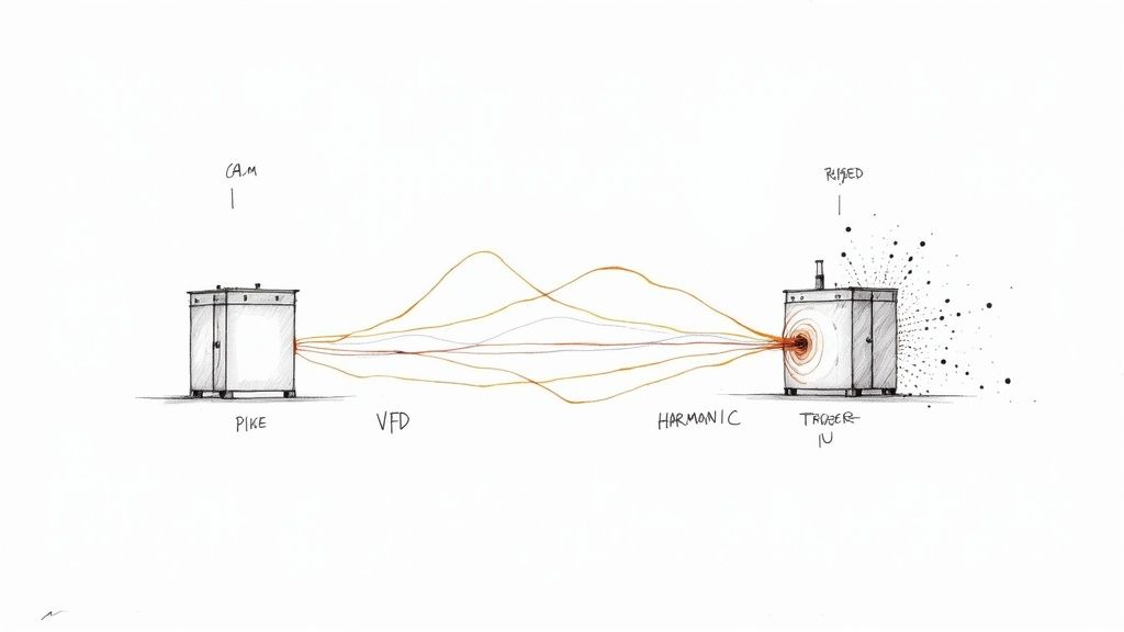
Let’s use an analogy. Imagine your facility’s power grid is a perfectly smooth-flowing river. A VFD, for all its benefits, is like a machine that starts chopping up that smooth flow, creating all sorts of turbulence and messy currents.
That electrical turbulence is what we call harmonic distortion. It pollutes the power quality for every piece of equipment connected to that grid. We get into the nitty-gritty of how they work in our guide on variable frequency drive basics, but the most important thing to know is that VFDs are non-linear loads.
Instead of drawing power in a smooth, continuous wave, they take it in short, sharp gulps. Those abrupt pulses are the very source of harmonic pollution.
The Real-World Impact of Harmonics
Ignoring harmonics isn't just a technical detail—it's a direct threat to your plant's reliability and your bottom line. This "dirty power" travels everywhere, causing all sorts of strange, intermittent problems that are a nightmare to diagnose.
Without a good filter, you’re likely to see issues like:
Overheating Equipment: Transformers, motors, and even wiring can start running dangerously hot, drastically shortening their service life.
Nuisance Tripping: Circuit breakers pop for no obvious reason, causing frustrating and expensive downtime.
Control System Glitches: PLCs, sensors, and even your network equipment can start acting up or failing because their power source is corrupted with noise.
Wasted System Capacity: Harmonics eat up the capacity of your electrical system, meaning you can't add new equipment without first making expensive upgrades.
A harmonic filter is essentially a water treatment plant for your electrical river. It intercepts the pollution from the VFD and restores the clean, smooth power that your other equipment needs to run properly.
A Growing Industrial Necessity
The link between VFDs and harmonics is so strong that the filter market is growing right alongside VFD adoption. Projections show the harmonic filter market climbing from USD 933.86 million in 2025 to over USD 1.18 billion by 2030.
This isn't a coincidence. As more industries rely on VFDs, they're discovering that a standard six-pulse drive can easily push distortion levels into a problematic 30–40% range if left unchecked. As companies get serious about reliability and meeting power quality standards, filters are moving from a "nice-to-have" to a must-have component. You can see more on this trend in this harmonic filters market forecast.
When it's time to choose a harmonic filter for your VFD, you’ll quickly find yourself at a fork in the road: Passive or Active. This isn't about picking the "best" one, but about finding the right tool for the job. The decision you make here will ripple through your system's performance, your budget, and even long-term reliability.
To get a grip on the difference, think of it like dealing with unwanted noise.
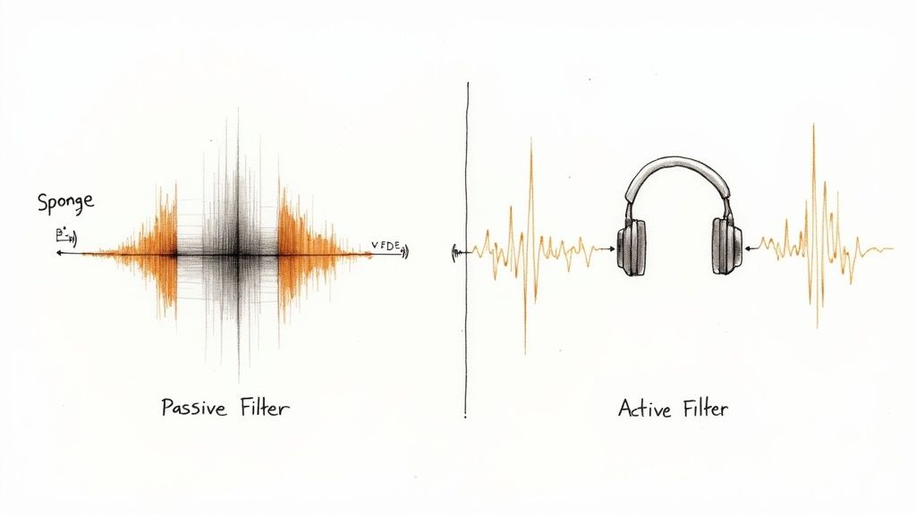
A passive filter is like a well-designed soundproofing panel. It’s made of specific materials—inductors, capacitors, and resistors—that are perfectly tuned to absorb a particular frequency of noise. It just sits there and does its one job really, really well.
An Active Harmonic Filter (AHF), on the other hand, is like a pair of high-end noise-canceling headphones. It actively listens to the noise, figures out its pattern, and generates an exact opposite sound wave to completely cancel it out in real time. It's a smart, dynamic solution.
The Passive Filter Approach
Passive filters are the tried-and-true workhorses of harmonic mitigation. They are built from simple components—inductors and capacitors—that are precisely tuned to a specific harmonic frequency. They create an easy path to ground, essentially trapping and diverting that specific flavor of electrical noise away from your system.
Because they are “tuned” for common troublemakers like the 5th or 7th harmonics that VFDs love to create, they are fantastic in predictable environments. If you have a steady load and know exactly what you’re dealing with, a passive filter is a robust and cost-effective solution.
Best For: Single VFDs or a bank of drives that all run at a consistent speed and load.
Example Application: Think of a big exhaust fan or a pump in an HVAC system that just runs at a steady clip all day long.
Key Advantage: They are simple, tough, and much easier on the initial budget. With fewer moving parts, there’s less that can go wrong.
But that specialization is also their biggest drawback. If your system’s frequency profile changes, or if the utility power feeding your plant is already messy, a passive filter can lose its effectiveness. In a worst-case scenario, a poorly matched passive filter can actually create resonance and make your harmonic problems even worse.
The Active Filter Advantage
Active Harmonic Filters are a whole different ballgame. They use sophisticated power electronics—fast-switching transistors (IGBTs) and a smart controller—to constantly watch the electrical system.
A current transformer (CT) acts as the filter's "ears," measuring the distorted current waveform coming from the VFD. The AHF’s controller instantly analyzes this dirty signal and injects a perfectly opposing current to cancel out the harmonic distortion. This happens thousands of times a second, allowing the filter to adapt on the fly to whatever the VFDs are doing.
An active filter doesn't just block noise; it actively erases it. By injecting a mirror-image counter-current, it forces the waveform drawn from the power grid back into a clean, smooth sine wave.
This incredible adaptability makes active filters the clear winner for complex facilities. If you’ve got multiple VFDs, loads that are all over the place, or you’re under the gun to meet tough power quality standards, an AHF is often the only way to get there. They can tackle a whole range of harmonics at once and even help out with power factor correction as a bonus.
Passive vs Active Harmonic Filters At a Glance
Choosing between these two technologies really boils down to balancing your immediate needs and your budget. Here’s a quick rundown of how they stack up.
Characteristic
Passive Filter
Active Filter
Mitigation Method
Diverts specific, targeted frequencies
Injects an opposing current to cancel distortion
Performance
Good for specific, predictable harmonics
Excellent, broad-spectrum correction
Adaptability
Fixed; performance can drop with system changes
Highly dynamic; adapts instantly to changing loads
Initial Cost
Lower
Higher (often 2-3x the cost of a passive unit)
Size
Can be quite large, especially for high amps
Generally more compact
Ideal Load
Stable, consistent loads
Dynamic, variable, and multiple non-linear loads
Complexity
Simple and rugged
Complex power electronics require skilled integration
For a facility with a lot of non-linear loads all feeding into a common bus, or for anyone who absolutely has to meet strict IEEE 519 standards, an active filter is almost always the answer. The upfront investment is higher, no doubt. But in complex industrial environments where uptime is everything, the superior performance and operational flexibility often deliver a far better return in the long run.
Playing by the Rules: Why IEEE 519 Matters
When we talk about standards like IEEE 519, it's easy to get lost in the numbers and think of it as just another compliance hurdle. But it’s much simpler than that. Think of it as being a good neighbor on the electrical grid. Your utility company works hard to deliver clean, stable power to your facility, and in return, they need you to avoid dumping electrical "noise" back onto the line.
That noise is what we call harmonic distortion, and it's a natural byproduct of modern equipment like VFDs. If every facility let its harmonics run wild, the combined effect could destabilize the entire grid. That’s why these standards exist—to keep the shared power source clean and reliable for everyone connected to it.
Finding the Line: The Point of Common Coupling
So, where do the utility police actually measure this "noise"? That happens at a specific spot called the Point of Common Coupling (PCC).
The PCC is simply the official handoff point where your facility’s electrical system connects to the utility's grid. Picture it like the water meter at your property line; it’s the exact spot where the utility company measures what you're sending back. It’s at this PCC where your harmonic levels have to meet the limits set by IEEE 519.
At its core, IEEE 519 is a gentleman's agreement. The utility promises to deliver clean power, and you promise not to pollute that shared power. Harmonic filters are what allow you to hold up your end of the bargain.
What the Numbers Actually Mean
IEEE 519 isn't a one-size-fits-all rule. The harmonic limits you need to hit will change based on your system's voltage and how much power you draw. The general rule of thumb? The bigger your service and the higher the voltage, the tighter the limits get.
The standard really boils down to two key things:
Total Harmonic Distortion (THD): This is the big-picture number. It’s an overall score that represents the total amount of harmonic noise you're creating.
Individual Harmonic Limits: The standard also gets specific, putting caps on the individual troublemakers—like the 5th, 7th, and 11th harmonics—that VFDs are notorious for producing.
These limits are always expressed as a percentage of your maximum load. A very common target, for instance, is keeping your Total Demand Distortion (TDD)—which is just THD measured under full load—below 5% at the PCC. To get there, you almost always need properly engineered harmonic filters for VFD applications.
Tackling harmonics does more than just keep the utility happy; it makes your own system more efficient. Cleaning up your power reduces heat and wasted energy, which can also help improve your power factor. If you want to go deeper on that, our guide on the power factor definition is a great place to start. In the end, meeting IEEE 519 standards isn't just about avoiding a penalty—it’s about running a smarter, more reliable, and more efficient operation.
How to Size and Select the Right Harmonic Filter
Choosing the right harmonic filter isn't like picking a part off a shelf. It’s much more like getting a prescription filled—it has to be the right solution for a specific problem. If you undersize it, the filter won't do its job. Oversize it, and you’re just wasting money. The sweet spot is finding a solution that cleans up your power just enough without over-engineering the fix.
This is where we move from theory into the real world. The entire process starts with one critical step: gathering the right data. Before you even glance at a product spec sheet, you need a clear, accurate picture of your electrical environment.
Start with a Power Quality Analysis
First thing's first: you need a power quality analysis. Skipping this is like a doctor prescribing medicine without running any tests—you're just guessing, and the consequences can be serious. This analysis gives you the hard data, the baseline you absolutely need to specify the right harmonic filter for your VFD.
The process involves hooking up a power quality meter at critical points in your system, especially at the Point of Common Coupling (PCC). This isn't a quick snapshot; the meter stays on for a period to capture the full ebb and flow of your facility's operational loads.
Here’s what you’re looking for:
Existing Background Distortion: What's the Total Harmonic Distortion (THD) on your system before adding the new VFD or filter? This tells you if you're starting with a clean slate or walking into an existing mess.
VFD Load Profile: How much current is the VFD actually drawing, and how much does it change? A fan running at a steady 80% speed creates a much different harmonic signature than a crane VFD with its wild, unpredictable load swings.
Specific Harmonic Orders: The analysis breaks down the distortion into its component parts—the 5th, 7th, 11th harmonics, and so on. This is crucial for picking a filter that targets the frequencies causing the most trouble.
System Impedance: You need to understand how "stiff" your electrical system is. This helps predict how the grid will react to both the VFD and the filter you're about to add, letting you sidestep dangerous resonance problems.
Decoding Filter Specifications
Once you have that data in hand, you can finally start looking at filters. The numbers on a spec sheet aren't just marketing fluff; they are performance metrics that should directly map back to the problems you just measured.
You'll see terms like correction current, which is the maximum amount of harmonic garbage the filter can actively cancel out. This number needs to be higher than the harmonic current your VFD is producing. You'll also find attenuation levels, often shown on a chart, which detail how well the filter knocks down specific harmonic orders.
Think of it this way: Your power quality analysis tells you the size and shape of your harmonic problem. The filter’s spec sheet tells you the size and shape of the solution it provides. Your job is to find the perfect match.
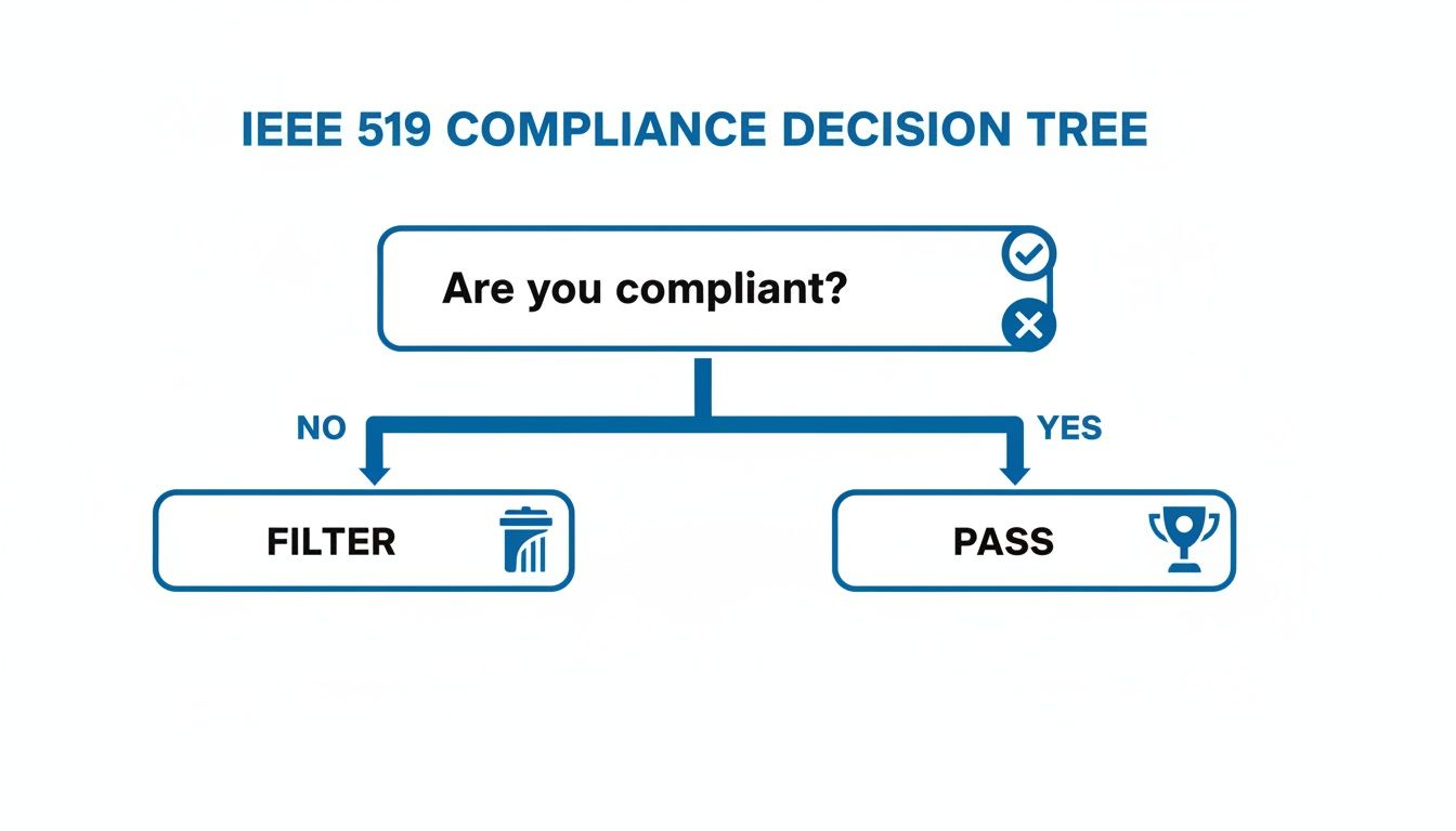
This decision tree gives you a great starting point for that first big question: are you compliant with standards like IEEE 519 right now?
If you land on the "Filter" branch, the real work begins. Now you have to match the right technology to your specific application.
Matching Filter Technology to Your Needs
The data from your analysis will point you toward the right type of filter. If your VFD runs a stable, predictable load, a simple and cost-effective passive filter tuned to the problem frequencies (usually the 5th and 7th) is often all you need.
But for more complex systems—think multiple VFDs or loads that are all over the place—an active harmonic filter (AHF) is almost always the better bet. We're seeing much faster adoption of active filters in the field because their performance is so immediate and measurable compared to older passive designs. Industry reports show the AHF market is growing quickly as facility managers realize the value of real-time, dynamic correction for fluctuating VFD loads.
A properly sized active filter can take your THD from an unfiltered mess down to single-digit territory, often <5–8%, which is what you need to meet strict utility limits. You can see more on this trend in this harmonic filter market analysis. By putting in the work to gather data upfront, you guarantee the filter you choose is a precise, effective, and financially sound investment.
Installation Best Practices for Peak Performance
You’ve done the hard work and selected the perfect harmonic filter for your VFD. That's a huge step, but the job is only half done. A top-of-the-line filter installed the wrong way is like buying a high-performance engine but forgetting to hook up the fuel line—all potential, no results.
Proper installation is what turns your investment into real-world performance. Getting it right from the start means you avoid common headaches like poor filter effectiveness, nagging safety hazards, and even interference with the very equipment you’re trying to protect.
Let's walk through the best practices that ensure your harmonic filter for VFD systems deliver from day one.
Location, Location, Location
Just like in real estate, placement is everything. The physical spot you choose for the filter in relation to the VFD has a massive impact on its effectiveness. Botch the location, and you’re setting yourself up for compromised performance and future maintenance nightmares.
Here’s what really matters for physical placement:
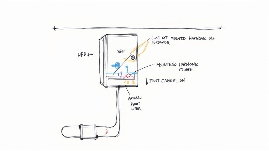
Get Close to the VFD: Your filter needs to be installed as close to the VFD as physically possible. Shorter conductor runs between the two mean less voltage drop and less radiated noise (EMI). Long cables can act like antennas, broadcasting the very electrical noise you’re trying to eliminate.
Give It Room to Breathe: Both VFDs and harmonic filters throw off a good bit of heat. Squeezing them into a stuffy, unventilated cabinet is a surefire way to cause overheating and premature failure. Always follow the manufacturer’s clearance requirements to ensure there's enough airflow. For bigger filters, this might even call for a dedicated ventilated cabinet.
Plan for Maintenance Access: While you want the filter snugged up next to the VFD, don't make it impossible to work on. Make sure a technician can safely get to the terminals for inspections, connections, or troubleshooting without having to kill power to half the plant.
The Critical Role of the Current Transformer
When you're dealing with an active harmonic filter (AHF), no single component is more crucial to its operation than the Current Transformer (CT).
Think of the CT as the filter's eyes and ears. It's constantly measuring the harmonic currents flowing from the VFD and feeding that data back to the filter's brain. The filter then uses this information to calculate the exact counter-current it needs to inject to cancel out the distortion.
If the CT is in the wrong place, the active filter is effectively blind. It can't see the harmonic distortion it's supposed to cancel, rendering the entire unit useless.
The CT must be installed so it measures the current of only the non-linear loads (the VFDs) it’s meant to correct. It should be placed after the filter's point of connection but before the VFDs. If you put it where it can also measure the filter’s own corrective current, you’ll create a confusing feedback loop that sends the system into a tailspin.
Wiring and Grounding Done Right
Sloppy wiring and poor grounding are probably the two most common culprits behind post-installation problems. These aren't just minor details—they're the foundation for a safe and effective system.
Use the Right Size Wire: Don't guess. Always use conductors sized for the filter's full load amperage, following all local electrical codes. Undersized wires can overheat, creating a serious fire hazard while also causing a voltage drop that cripples the filter's performance.
Keep Power and Control Separate: Make it a rule to route your low-voltage control wires in a separate path from the high-power cables. Running them together in the same conduit is an open invitation for noise to bleed into the control circuits, which can cause erratic and unpredictable filter behavior.
A Solid Ground is Non-Negotiable: A clean, low-impedance ground path is absolutely essential. It’s not just for safety; it’s what gives all that electrical noise a path away from your sensitive equipment. Use the dedicated grounding lug on the filter and connect it directly to the main system ground. No shortcuts.
Calculating the ROI of Harmonic Filtering
So, how do you justify the cost of a harmonic filter to the people signing the checks? It’s one thing to talk about meeting standards like IEEE 519, but the most convincing argument always comes down to the numbers. You have to prove that a filter isn't just another line-item expense—it's a smart investment that pays for itself.
Calculating the Return on Investment (ROI) is how you shift the conversation from a technical problem to a financial solution. A well-chosen filter doesn't just cost money; it makes and saves money over time, often in ways that are easy to miss. By putting real dollars to the benefits, you can show that doing nothing is actually the most expensive option.
Quantifying the Tangible Savings
The payoff from clean power goes way beyond just ducking utility fines. The real money is found in making your whole operation more efficient and reliable. These aren't just fuzzy concepts; they show up as real dollars on your balance sheet.
When building your case, you’ll want to hit these three financial pillars hard:
Reduced Energy Waste: Think of harmonic currents as electrical "junk food." They do nothing but create extra heat in your transformers, cables, and motor windings without contributing any real work. This wasted power, known as I²R losses, pads your utility bill every month. A filter cuts out this junk, which means you stop paying for energy that's just turning into heat. We dive deeper into this in our guide on VFD energy savings.
Extended Equipment Lifespan: That excess heat isn't just wasting energy; it’s actively cooking your equipment from the inside out. Transformers and motors running hot because of harmonics are on a fast track to failure. A filter acts like a bodyguard for these critical, expensive assets, helping them last longer and pushing huge replacement costs further down the road.
Minimized Costly Downtime: Nothing kills profits like an unplanned shutdown. Harmonics are a notorious cause of those frustrating "nuisance trips," where breakers pop for no clear reason, or sensitive PLCs and controls get scrambled, bringing a production line to a dead stop. By cleaning up the power, a filter stops these disruptive and incredibly expensive interruptions before they happen.
A Real-World ROI Scenario
Let's put some numbers to it. Picture a mid-sized manufacturing plant with a bunch of VFDs on its main production lines. Before installing filters, they were burning through about one oversized motor a year from overheating, costing them $15,000 a pop. On top of that, nuisance trips were causing about four hours of unplanned downtime a year, and every hour the line was down cost them $10,000 in lost production.
Here’s how the math breaks down for them:
Annual Cost of Downtime: 4 hours x $10,000/hour = $40,000
Annual Motor Replacement Cost: 1 motor x $15,000 = $15,000
Total Annual Avoidable Costs: $40,000 + $15,000 = $55,000
By investing $70,000 in a properly sized active harmonic filter, the facility could see a full payback in just over a year. After that, they’d be pocketing an extra $55,000 in savings, year after year.
This kind of breakdown changes everything. The filter is no longer just something you have to buy for compliance. It becomes a proactive move to boost reliability and efficiency. If you need to build an even more detailed business case, there are plenty of great ROI calculation resources out there that can help.
Common Questions About VFD Harmonic Filters
When you start digging into harmonic filters for VFDs, a bunch of practical questions pop up. When do I actually need one? Where does it go? Why is it so important? These things are absolutely critical for keeping your electrical system healthy, but it's easy to get bogged down in the technical details.
Let's cut through the noise. Here are some straightforward answers to the questions we hear most often, so you can make the right call and troubleshoot with confidence.
Do All VFDs Require a Harmonic Filter?
Not every single VFD needs a filter right out of the box, but in most real-world industrial and commercial shops, it’s something you have to seriously consider. The real decision comes down to a few key things: how big your drive is compared to your whole power system, how sensitive other equipment on the same circuit is, and what your local utility demands (like meeting the IEEE 519 standard).
Sure, one little VFD on a massive, bulletproof electrical system probably won’t cause enough of a ruckus to matter. But the moment you start adding multiple VFDs, or one single large drive, that harmonic noise adds up fast. In those cases, a filter stops being a "nice-to-have" and becomes essential for preventing system-wide headaches and staying compliant.
What Is Total Harmonic Distortion (THD)?
Total Harmonic Distortion, or THD, is the go-to metric for measuring the "cleanliness" of your power. Think of it like a single grade that tells you how much electrical garbage is polluting your power signal compared to a perfect, clean sine wave.
A low THD percentage means you’ve got clean, stable power. A high THD means you've got significant distortion that can beat up your equipment. Standards like IEEE 519 put hard limits on THD to keep the grid stable, often telling facilities they have to keep distortion below 5% where their power comes in.
Can a Harmonic Filter Improve Energy Efficiency?
Yes, absolutely. This is a big one that often gets overlooked. Harmonic currents are just wasted energy. They don't do any useful work—they can't help turn a motor shaft. All they do is create destructive extra heat in your transformers, wiring, and the motors themselves. That's pure wasted electricity, and you're paying for it on your utility bill.
By knocking out these useless harmonic currents, a filter cuts down on that wasted heat, what we call I²R losses. The result is a more efficient electrical system, less heat stress on your gear, and real, measurable energy savings over time.
Where Should a Harmonic Filter Be Installed?
The rule of thumb is that harmonic filters get installed on the "line side" of the system. This just means you place the filter between your main power feed and the Variable Frequency Drive.
Putting it there is strategic. It allows the filter to catch and scrub out the harmonic currents the VFD creates before they can bleed back into the rest of your facility's electrical network or escape out onto the utility grid. Getting the placement right isn't optional—it’s what makes the filter do its job and protect your whole system.
At E & I Sales, we live and breathe this stuff. We engineer rugged, reliable motor control solutions that keep your plant running without a hitch. If you're trying to sort out VFDs and harmonic mitigation, our team has the field experience to design and build a system that nails your exact requirements.
Contact us to make sure your power quality is locked in. Learn more at https://eandisales.com.
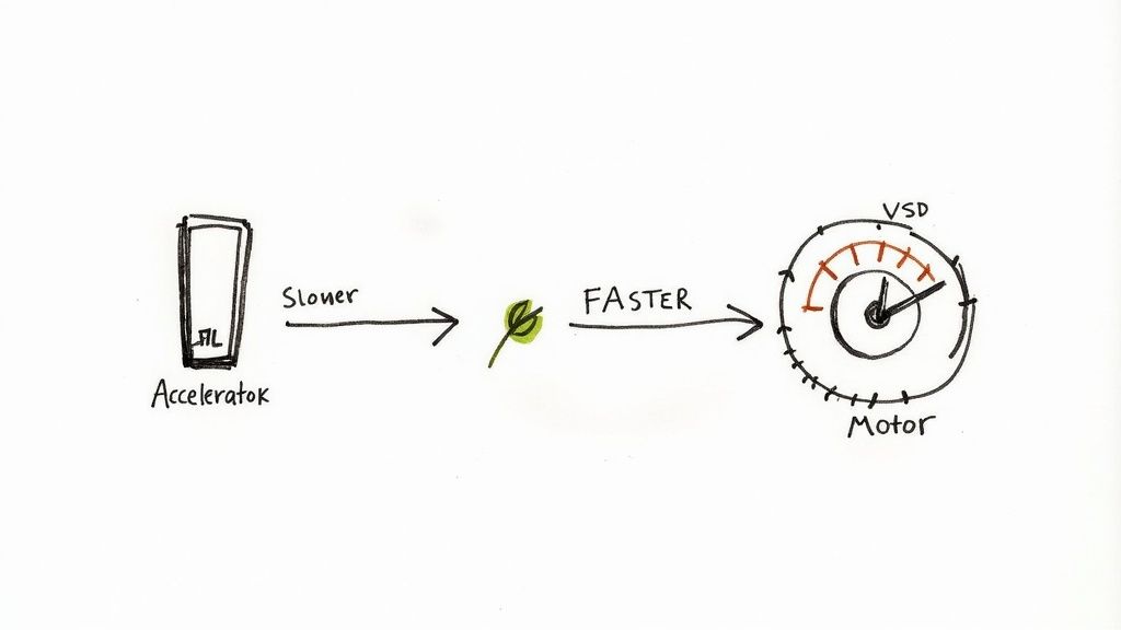
Think of a Variable Speed Drive (VSD) as the accelerator for an electric motor. Instead of being stuck at one speed—full throttle—it lets the motor run at the exact speed needed for the job at hand. This simple but powerful capability is what unlocks incredible energy savings and precise process control.
It all comes down to adjusting the electrical frequency fed to the motor.
Unlocking Smarter Motor Control
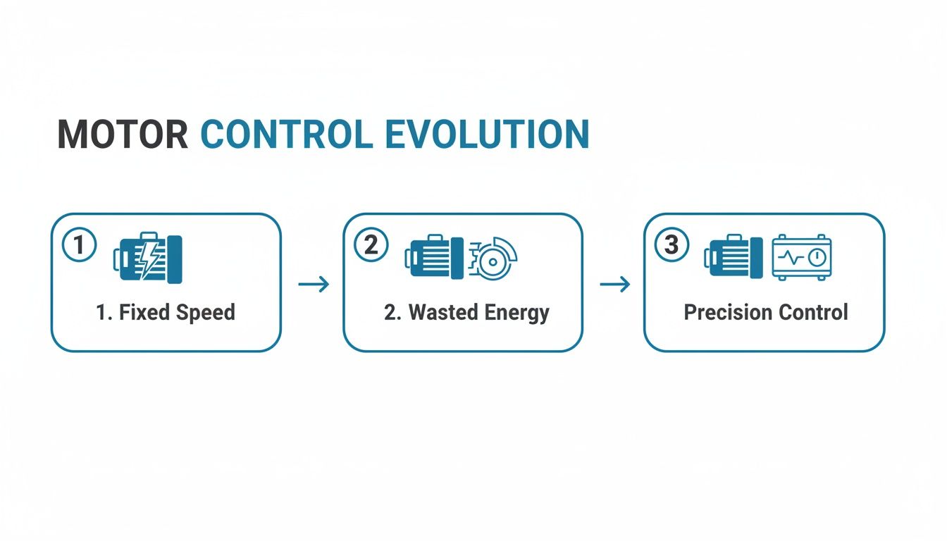
Imagine trying to drive your car with only two options: full stop or pedal to the floor. That’s essentially how countless traditional electric motors work. They’re either off or running at a constant, maximum speed. While simple, this all-or-nothing approach is wildly inefficient for most real-world jobs.
A VSD completely flips that script. Instead of relying on clumsy mechanical parts like dampers or valves to throttle down the output, the VSD acts as the motor's brain. It intelligently dials the motor's speed up or down to perfectly match the application's real-time demand, ensuring not a single watt of power is wasted.
From Wasted Energy to Precise Performance
At its core, a VSD takes the standard, fixed-frequency power from the grid and converts it into a variable-frequency power source for the motor. Since an AC motor's speed is directly linked to the frequency of its power supply, changing the frequency means you change the speed. Simple as that.
This opens the door to some serious benefits:
Massive Energy Savings: Just by running a motor only as fast as it needs to, VSDs can slash energy consumption by up to 60%, especially in common applications like pumps and fans.
Enhanced Process Control: VSDs give you pinpoint control over flow, pressure, and speed. This leads directly to higher-quality products and more consistent operations.
Reduced Mechanical Stress: The soft-start and stop capabilities of a VSD get rid of the sudden jolt that hammers equipment. This extends the life of critical components like belts, gears, and bearings.
It’s a common myth that VSDs are only for complex, high-tech systems. The truth is, their ability to match a motor’s output to the actual load makes them a smart financial move for almost anything, from a simple conveyor belt to a sophisticated HVAC system.
VSD vs. VFD: What's the Difference?
You'll often hear the terms VSD (Variable Speed Drive) and VFD (Variable Frequency Drive) thrown around like they're the same thing—and for the most part, they are.
When we're talking about AC motors, they refer to the exact same technology. VFD is just a more specific term that describes how the drive controls speed: by varying the frequency. VSD is a broader, more general term. But in today's industrial world, if someone says VSD, they almost always mean a VFD. If you want to get into the technical nitty-gritty, you can learn more about AC motor variable speed control and the principles behind it.
To put it all in perspective, here’s a quick rundown of how a VSD changes the game compared to old-school motor control.
VSD Control vs Traditional Motor Control At a Glance
Feature
Traditional Motor (Fixed Speed)
VSD Controlled Motor (Variable Speed)
Speed Control
Runs at a single, constant speed.
Speed is fully adjustable from zero to maximum.
Energy Efficiency
Often inefficient, especially at partial loads.
Highly efficient, matching energy use to demand.
Process Control
Limited; requires mechanical throttling.
Precise and immediate control over processes.
Equipment Wear
High mechanical stress during startup.
Smooth starts and stops reduce wear and tear.
As you can see, the difference is night and day. A VSD gives you the flexibility, efficiency, and control that a fixed-speed motor simply can't match.
How a Variable Speed Drive Actually Works
At its core, a variable speed drive is like a sophisticated power translator for an electric motor. It takes the standard, fixed-frequency AC power from the grid and cleverly transforms it into a new AC power source where the frequency can be adjusted on the fly. This ability to manipulate frequency is the secret to controlling a motor’s speed with surgical precision.
Think of it as a three-stage journey that turns raw, inflexible power into smart, adaptable energy. Each stage has a specific job, working in perfect sync to give you total command over your motor. The entire process is a seamless AC-to-DC-to-AC conversion that happens in the blink of an eye.
This is a big deal because, without this control, you’re stuck with a motor that only knows one speed: full blast.
As the graphic shows, running a motor at full speed when it isn't needed is the same as leaving cash on the table. A VSD fixes that.
Stage 1: The Rectifier Converts AC to DC
The journey starts at the rectifier, which is the VSD’s front door for incoming power. Its one and only job is to take the alternating current (AC) from your facility and convert it into direct current (DC). The AC power from the wall outlet naturally flows back and forth in a sine wave, which is great for long-distance transmission but terrible for precise control.
To build an adjustable output, the VSD first needs a stable, one-way power source to work with. The rectifier, usually built with high-power diodes, acts like a series of one-way valves. It lets electricity flow in but not back out, effectively ironing out the AC waves into a steady stream of DC voltage.
Stage 2: The DC Bus Stores and Smooths the Power
Once converted, this raw DC power flows into the DC bus, which acts like a power reservoir. It’s mainly made up of big capacitors that store the electrical energy, making sure a clean and stable supply is ready for the final stage.
Picture the DC bus as the calm water held in a reservoir behind a dam. The rectifier fills it up, and the capacitors ensure the water level (voltage) stays perfectly constant, filtering out any ripples or hiccups from the conversion. This smooth, stored DC power is absolutely essential for creating a clean AC waveform on the other side.
A stable DC bus is the foundation of the drive's performance. Without it, the final AC output to the motor would be choppy and erratic, leading to poor performance and even potential damage.
Stage 3: The Inverter Creates a New, Adjustable AC Signal
This is it—the final and most critical stage is the inverter. This is where the real magic of variable speed control happens. The inverter takes that smooth DC power from the bus and, using a set of incredibly fast electronic switches (typically Insulated Gate Bipolar Transistors, or IGBTs), chops it up into thousands of precisely timed pulses per second.
By controlling the timing and width of these pulses—a technique called Pulse Width Modulation (PWM)—the inverter can build a brand-new, synthetic AC sine wave from scratch. And here's the key: the frequency of this new wave is completely under your control.
To run the motor slower, the inverter creates a lower-frequency AC waveform.
To run the motor faster, it generates a higher-frequency waveform.
This newly minted, variable-frequency AC power is then fed to the motor, dictating its exact rotational speed. The motor simply follows the frequency it’s given, giving you the power to match its output perfectly to what your application actually needs. No more waste, just pure, precise control.
The Main Components and Types of VSDs
To really get what a variable speed drive is, you have to look under the hood. Think of it like a car engine—you have the block, pistons, and crankshaft all working in concert. A VSD is no different; it’s an assembly of key electronic components that have to work together perfectly to give you that precise motor control.
Each part has a specific job in the AC-to-DC-to-AC power conversion process that makes the whole thing possible.
While the big hardware handles the power, a sophisticated control unit is the maestro orchestrating the whole performance.
Unpacking the Core Hardware
A VSD isn't just one magic box. It’s a system made up of four essential parts, and knowing what each one does makes it much clearer how the drive pulls off its magic trick.
Rectifier: This is where the power from the grid first enters the drive. Its only job is to take that incoming alternating current (AC) and, using a series of diodes, turn it into direct current (DC).
DC Bus: Basically a big electrical reservoir made of capacitors. The DC bus takes the power from the rectifier, smooths it out, and stores it. This ensures the next stage gets a stable, clean supply of DC power to work with.
Inverter: This is the real heart of the VSD. It takes that smooth DC power from the bus and, using incredibly fast-switching transistors (usually IGBTs), chops it up to build a brand-new, synthetic AC waveform with whatever frequency and voltage is needed.
Control Unit: The brain of the whole operation. This microprocessor is constantly monitoring motor feedback, user commands, and system status. It tells the inverter exactly what kind of waveform to create to hit the target speed and torque.
These four pieces work in lockstep to turn a simple command—like "run this pump at 75% speed"—into a precisely engineered electrical output.
The Major Categories of VSDs
Not all drives are built the same. They come in different flavors, each designed with specific technologies for different jobs, from simply slowing down a fan to running high-precision robotics. The two main categories are defined by how they handle the power internally.
Choosing the right type of VSD is less about which one is "better" and more about matching the technology to the demands of the job. A high-performance drive is overkill for a simple pump, while a basic drive can't handle a complex servo application.
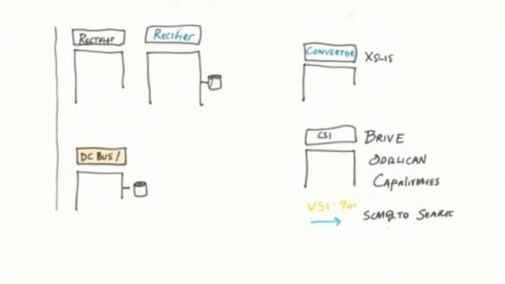
The most common distinction you'll run into is between Voltage Source Inverters and Current Source Inverters.
Voltage Source Inverters (VSI): This is the workhorse of the industry. By far the most common type of VSD you’ll find, a VSI creates a variable voltage output. This makes them incredibly versatile, cost-effective, and a perfect fit for the vast majority of industrial applications.
Current Source Inverters (CSI): You don't see these as often. CSIs are typically reserved for very high-power, medium-voltage applications—think massive industrial fans or pumps. They regulate current instead of voltage, which gives them unique advantages for controlling huge motors, but they come with a higher price tag and more complexity.
Beyond that fundamental split, VSDs are also grouped by their performance capabilities. A standard drive, often called a V/Hz or scalar drive, is perfect for simple tasks where you just need to adjust speed, like on a fan or pump, and don't need dead-on torque control.
For the more demanding jobs, you step up to vector control or servo drives. These high-performance drives use sophisticated algorithms to independently manage both the motor's speed and torque with incredible accuracy. This makes them essential for things like machine tools, complex conveyors, and robotics, where precise positioning and a dynamic response are non-negotiable.
The Business Case for Installing VSDs
While the tech behind a variable speed drive is interesting, the real question for any business is simple: why should you invest in one?
It really comes down to a powerful mix of massive energy savings, tighter process control, and better long-term equipment health. A VSD isn't just an operational upgrade; it’s a smart financial move with a clear—and often very quick—return on investment.
The biggest benefit, the one that gets everyone’s attention, is the dramatic drop in energy consumption. This is especially true for anything with pumps and fans, which follow a fascinating set of rules known as the Affinity Laws.
These laws show a powerful link between a motor's speed and its power draw. In short, the power needed is proportional to the cube of the motor's speed. This creates an exponential curve where even a tiny reduction in speed leads to a massive drop in energy use.
The Power of the Affinity Laws
Think about it like this: if you slow a fan down by just 20%, you don't save 20% on your energy bill. Thanks to the Affinity Laws, that 20% speed reduction actually slashes the fan's energy use by nearly 50%.
That’s a complete game-changer for facilities with big HVAC systems or fluid-pumping operations. A seemingly minor tweak becomes a major cost-cutting measure. You can see how this plays out in the real world in our detailed look at VFD energy savings.
This is where VSDs really shine. Instead of running a pump at full blast and using a valve to choke the flow—which is like driving with one foot on the gas and the other on the brake—a VSD just slows the motor down to deliver the exact flow you need.
By precisely matching motor speed to the load demand, a VSD eliminates the wasted energy inherent in fixed-speed systems. This isn’t just incremental improvement; for many businesses, it’s the single most impactful energy efficiency upgrade they can make.
More Than Just Energy Savings
The energy savings are fantastic, but the business case for VSDs goes way beyond a lower utility bill. The enhanced control and gentler operation they provide bring a ton of other valuable perks to the table.
Improved Process Control: For any application needing precise pressure, flow, or tension, VSDs offer incredible accuracy. They can hold a setpoint with rock-solid stability, which leads to better product quality, less wasted material, and more consistent output.
Reduced Mechanical Stress: A standard motor kicks on with a violent, instant jolt of power. That shockwave slams into belts, gears, and couplings. A VSD, on the other hand, gives you a smooth, controlled "soft start," gradually ramping up the motor's speed. This gentle acceleration drastically cuts down on mechanical wear and tear, making your equipment last longer and lowering maintenance costs.
Lower Maintenance and Repair Costs: When equipment runs smoother and only as fast as necessary, parts don't wear out as quickly. Fewer emergency repairs mean less unplanned downtime, which directly protects your bottom line.
The market is certainly taking notice. Global VFD market projections show growth from USD 24.7 billion in 2025 to USD 32.0 billion by 2030. This trend is fueled by real results; in water treatment plants, for example, VFDs can cut pumping energy by 20-60%. A single 100 kW pump with a VFD can save 200,000 kWh a year, which can mean over $20,000 back in your pocket.
For manufacturers, figuring out smart strategies to reduce manufacturing costs is always a priority, and VSDs are a huge piece of that puzzle. By combining direct energy savings with less maintenance and better process quality, a VSD is a multi-pronged attack on operational spending that directly boosts profitability.
How to Select the Right VSD for Your Application
Choosing the right variable speed drive isn't just about grabbing one off the shelf. It’s a crucial decision that hinges on a deep understanding of your motor, the job it’s doing, and the environment it lives in. Get this right, and you'll unlock those promised energy savings and gain incredible process control. Get it wrong, and you're looking at performance headaches, premature failure, and money down the drain.
The whole process kicks off with the basics: your motor’s nameplate. That little metal plate is packed with the critical data you need to size the VSD correctly.
Sizing Your Drive with Motor and Application Data
Properly sizing a VSD is hands-down the most important first step. An undersized drive will constantly trip on faults and eventually burn out, while an oversized one is just a waste of capital. The goal is to perfectly match the drive's capabilities to both the motor it's controlling and the actual work that motor has to do.
First things first, grab these key details from the motor’s nameplate:
Full Load Amps (FLA): This is the big one. Your VSD absolutely must be rated to handle the motor’s maximum current draw when it's working its hardest.
Horsepower (HP) or Kilowatts (kW): While amps are the priority, the HP rating is a great way to double-check that you’re in the right ballpark.
Voltage: Simple but critical. The drive's input voltage has to match your available power supply, whether that’s 480V, 240V, or something else.
Beyond the motor itself, you have to think about the application’s torque requirements—the amount of rotational force the motor needs to generate. You can dive deeper into the fundamentals in our guide on how to calculate motor torque.
A common mistake is sizing a drive based on horsepower alone. Always, always prioritize the motor's Full Load Amps (FLA). It’s a far more accurate measure of the electrical load the VSD will actually see.
Applications typically fall into two torque profiles, and your VSD choice needs to reflect which one you're dealing with:
Variable Torque: Think centrifugal fans and pumps. The torque needed goes up as the speed increases. Since they require very little torque at low speeds, these applications are the superstars for massive energy savings.
Constant Torque: This is your world of conveyors, mixers, and extruders. They demand the same amount of muscle from the motor whether it’s crawling or running at full tilt. These loads need a robust VSD that can deliver consistent, high torque even at very low RPMs.
Tackling Power Quality and Harmonic Distortion
One of the biggest hurdles when integrating a VSD is harmonic distortion. In plain English, the super-fast electronic switching happening inside the drive creates electrical "noise" that can pollute your facility's power grid. This distortion can wreak havoc on other sensitive electronic equipment sharing the same circuit, causing bizarre malfunctions or even permanent damage.
Luckily, this is a well-known issue with proven fixes. The most common way to fight back is by installing a line reactor or a specialized harmonic filter. A line reactor is basically an inductor coil that you place on the input side of the VSD. It acts like an electrical shock absorber, smoothing out the current and filtering out a huge chunk of those damaging harmonics. For more severe cases, you might step up to a dedicated active or passive harmonic filter to guarantee clean power.
Considering Environmental and Compliance Factors
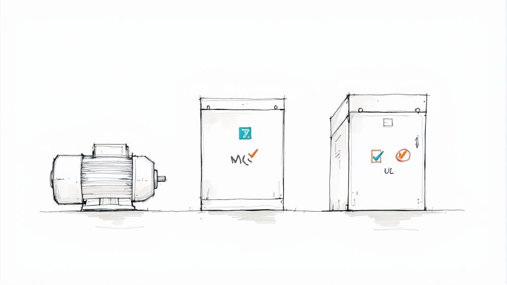
Finally, a VSD has to be tough enough to survive in its home. The drive's enclosure is rated to protect its delicate electronics from things like dust, moisture, and chemical spray. These ratings are standardized by NEMA (National Electrical Manufacturers Association).
NEMA 1: Your standard choice for clean, dry, indoor spots.
NEMA 12: Offers protection from circulating dust and light, non-corrosive drips.
NEMA 4X: The workhorse for harsh, wet, or wash-down areas, built to resist corrosion.
Meeting safety standards from organizations like UL (Underwriters Laboratories) is also completely non-negotiable. A properly rated and certified drive is essential for meeting regulations and protecting both people and equipment. This kind of foresight is becoming even more critical as the VSD market continues to explode, with projections showing it growing from USD 28.38 billion in 2024 to USD 39.67 billion by 2030, largely thanks to energy efficiency mandates.
VSDs in Action Across Different Industries
The theory behind a variable speed drive is one thing, but seeing it solve real-world problems is where the magic happens. This isn't just about technical specs on a data sheet; it's about making industrial and commercial operations smarter, more efficient, and a whole lot more reliable.
From keeping a massive office building comfortable to making sure your city's water flows steadily, VSDs are the unsung heroes working behind the scenes. Their core strength is simple but powerful: they match a motor's speed to the actual work that needs to be done. This is what unlocks huge benefits across completely different sectors.
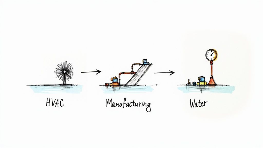
Optimizing Commercial HVAC Systems
In any large commercial building, the Heating, Ventilation, and Air Conditioning (HVAC) system is an absolute energy hog. Traditionally, the fans and pumps that push air and water just run at full tilt all day long. To control the output, they use mechanical dampers or valves to choke off the flow—basically like driving your car with the gas pedal floored and using the brake to control your speed. It’s incredibly wasteful.
This is where VSDs completely change the game. By installing a VSD on an HVAC fan motor, the system can dial its speed up or down based on what’s actually happening, like building occupancy or the outside temperature. On a mild day, the fan just slows down, and because of the Fan Affinity Laws, it consumes exponentially less power while keeping everyone perfectly comfortable. This intelligent control not only crushes energy bills but also makes the building quieter and helps the equipment last longer.
Synchronizing Manufacturing Production Lines
Manufacturing plants live and die by precision and timing. Picture a production line with multiple conveyor belts moving products from one station to the next. If one belt runs just a little too fast or slow, you get bottlenecks, damaged products, or even a full-blown line shutdown, all of which cost a fortune.
VSDs are the perfect fix. They give operators pinpoint control over each individual conveyor motor. You can fine-tune the speed of different sections to create a perfectly synchronized flow, ensuring a seamless handoff from one process to the next. This kind of control slashes downtime, improves product quality by stopping pile-ups, and makes the whole plant run more efficiently. The smooth starts and stops also eliminate mechanical shock, which protects expensive machinery from wear and tear.
The global impact of this technology is undeniable. The top 10 VSD manufacturers now hold over 60% of the global market share, a testament to the technology's widespread adoption and proven value in optimizing industrial operations.
Ensuring Reliable Municipal Water Pressure
For a city's water system, keeping water pressure consistent across miles of pipes is a massive challenge. Running pumps at full speed 24/7 burns through an insane amount of electricity and puts constant stress on the infrastructure, leading to damaging pressure surges (water hammer) and expensive leaks.
By putting VSDs on their water pumps, municipalities can hold a steady, reliable pressure no matter how much water people are using. When everyone wakes up and starts their morning showers, the VSD seamlessly ramps the pumps up. In the middle of the night, when demand drops, it dials them way back down. This prevents dangerous water hammer, reduces the number of pipe breaks, and leads to huge energy savings for the community.
You see a similar logic in the oil & gas sector, where applying VFDs to pumps can cut downtime by 15%, saving millions at a single site every year. If you want to dig deeper, you can learn more about the growth and dynamics of the VFD market and its massive industrial impact.
Common Questions About Variable Speed Drives
We’ve covered a lot of ground on what a variable speed drive is and how it works. But if you’ve still got a few questions rattling around, you’re not alone. Let’s tackle some of the most common ones we hear from folks in the field.
What Is the Difference Between a VSD and a VFD?
Walk onto any plant floor, and you'll hear people use VSD (Variable Speed Drive) and VFD (Variable Frequency Drive) interchangeably. For all practical purposes, they're talking about the same piece of equipment.
Technically, VFD is the more precise term because it describes how the drive controls the motor's speed—by changing the electrical frequency. VSD is more of a catch-all term. But in the real world, if someone's talking about a VSD for an AC motor, they mean a VFD. Simple as that.
Can You Use a VSD on Any Motor?
That’s a hard no. Slapping a VSD on a standard motor is a recipe for disaster. Drives are designed to work with special inverter-duty motors. These motors have beefed-up insulation and a design that can handle the unique electrical stress a drive puts on them.
If you try to run a general-purpose motor with a VSD, you’re asking for trouble. It’ll likely overheat, the insulation will break down, and you’ll burn out the motor long before its time. Always check the motor's nameplate—if it doesn’t say "inverter-duty" or "VFD-rated," don't pair it with a drive.
The biggest win with a VSD is the hit it makes on your power bill. The Compressed Air & Gas Institute found that a variable speed drive can knock energy costs down by an average of 33% in many setups, often paying for itself in just two to five years.
How Much Energy Can a VSD Really Save?
The savings can be massive, especially for pump and fan applications. It all comes down to a bit of physics called the Affinity Laws, which show that even a small drop in motor speed creates a huge drop in energy use.
Think about it this way: slowing a fan down by just 20% can cut its energy consumption by almost 50%. While your exact savings will depend on your specific setup, it's not uncommon to see reductions anywhere from 20% to 60%.
At E & I Sales, we do more than just sell parts—we build complete motor control solutions that work. From picking out the perfect VSD to designing, building, and commissioning a UL-listed control panel, our experts are here to make sure your project is a success from start to finish. See what our custom integration and packaging services can do for you.
Before you even think about touching a wire, stop and look at the motor's nameplate. This little metal tag is your blueprint for a safe and successful hookup, and it's the foundation for any accurate three phase motor wiring diagram. Honestly, getting this part right is non-negotiable for any tech who wants a motor to run reliably for years to come.
Unlocking the Secrets on a Motor Nameplate
I can't tell you how many times I've seen a motor fail prematurely because someone misread the nameplate. It's not a small mistake—it’s a direct path to fried windings, tripped breakers, and genuinely hazardous conditions. That plate is packed with critical data that dictates everything from your overload settings to whether the motor is even right for the job. It's the most reliable source of truth you have, far more trustworthy than a generic schematic you find online.
A lot of guys will just glance at the horsepower (HP) and voltage and call it a day. While those are obviously important, they're just the start of the story. The real details that prevent callbacks and keep things safe are buried in the other specs.
Key Data Points You Cannot Ignore
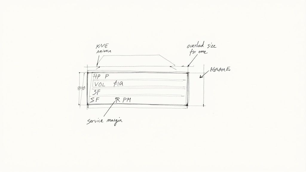
When you're inspecting that nameplate, zero in on these values. Each one plays a specific role in how you'll wire and protect the motor.
Voltage (VOLTS): This tells you the design voltage(s). You'll often see dual-voltage motors, like those marked 230/460V, which need a specific wiring configuration for each. Hooking up a motor wired for 230V to a 460V supply will instantly let the smoke out. It's a fatal mistake.
Full-Load Amps (FLA or AMPS): This is what the motor will draw when it's working at its rated horsepower. This number is absolutely critical. You use the FLA—not the horsepower—to size your overload protection.
Service Factor (SF): A service factor of 1.15 means the motor can handle a 15% overload for short periods without damage. If you see an SF of 1.0, it has zero built-in safety margin and you should never push it past its rated HP.
NEMA Design Letter: This letter (usually B, C, or D) gives you huge clues about the motor's torque characteristics. A Design B motor is your standard workhorse. A Design C gives you higher starting torque, perfect for something like a loaded conveyor. Knowing the difference is key, and if you really want to get into the weeds, you can learn more about torque calculation for motor applications to perfectly match a motor to its load.
A classic field mistake is setting thermal overloads based on a generic horsepower chart. Don't do it. Always use the specific FLA printed on the nameplate. Using a chart can lead to nuisance tripping if the motor's actual draw is higher, or worse, a complete failure to protect the motor if it's lower. The nameplate never lies.
Applying Nameplate Data in a Real Scenario
Let's say you're swapping out a motor on a packaging conveyor. The old one was a 10 HP, 460V motor. The new one you're putting in has the same specs on the box. But when you check the nameplate, you see the new motor has a lower FLA of 12 amps, while the old one was rated for 14 amps.
If you just hook it up without adjusting the overload relay in the starter, you've left that new motor completely unprotected. The relay is still set for the old motor and won't trip until the current hits a point that's already cooking the new motor's windings, drastically cutting its lifespan short.
One more thing: look for a wiring diagram number printed on the plate. This points to the exact connection scheme for the motor's leads (for high vs. low voltage, for example). The diagram is usually on a sticker inside the terminal box cover, but if that's missing or ruined, the nameplate is your permanent backup. That diagram is the heart of your plan.
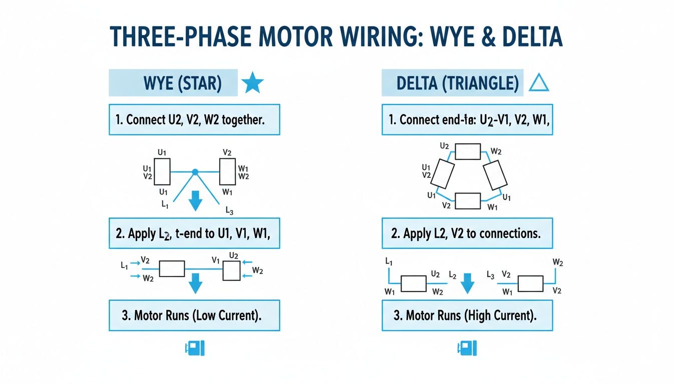
Choosing Between Wye and Delta Wiring
When you're staring at a three-phase motor's wiring diagram, the choice between a Wye and Delta connection is one of those fundamental decisions that has massive real-world consequences. This isn't just theory; it directly impacts your motor’s starting torque and whether it will even work with your plant's supply voltage.
Getting this right is what separates a technician who just follows a diagram from an engineer who truly understands and optimizes the system.
Pop open the motor's terminal box—often called the peckerhead—and the number of leads you find tells a story. You could see 3, 6, 9, or even 12 leads. This isn't arbitrary. Each count unlocks different wiring options, dictating how the internal windings are grouped and which voltages the motor can handle.
This built-in flexibility is a huge win for everyone. Manufacturers can produce dual-voltage motors that can be adapted in the field, which simplifies inventory and makes them useful across the globe. All it takes is reconfiguring how you connect the leads. For a deeper dive, check out these standard three-phase connections to see the common setups.
Wye Connection: The High-Voltage Workhorse
A Wye connection, also called a "Star" connection because of how it looks on a schematic, is your go-to for higher voltage applications. On a dual-voltage 230/460V motor, for instance, you'd wire it in Wye to run on your 460V supply.
In a Wye setup, one end of each of the three windings is tied together at a common neutral point. The other ends are then connected to your incoming L1, L2, and L3 power lines. This clever arrangement means each individual winding sees a lower voltage—specifically, the line voltage divided by the square root of 3 (about 1.732).
This lower voltage across each winding gives you some distinct advantages:
Lower Starting Current: This is a big one. It reduces that initial electrical jolt on your system when the motor kicks on.
Smoother Starts: The resulting lower starting torque is much gentler on connected machinery, making it ideal for equipment like fans and centrifugal pumps.
A Natural Neutral Point: This can be handy for certain control circuits or monitoring systems that need a neutral reference.
The core principle of Wye wiring is voltage management. By effectively putting the windings in series, you increase their impedance, allowing the motor to run safely on a higher supply voltage without burning up. Get this wrong, and you're looking at catastrophic winding damage.
Delta Connection: The Torque King
When you need raw power, you turn to the Delta connection. This setup is built to deliver the high starting torque required to get heavy loads moving—think fully loaded conveyors, big air compressors, or positive displacement pumps. For that same 230/460V motor, you'd wire it in Delta to run on the lower 230V supply.
In a Delta configuration, the windings are connected end-to-end, forming a closed triangle that looks like the Greek letter delta (Δ). Each corner of the triangle is then fed by one of the three power phases. In this arrangement, every winding gets the full line voltage, which is why it's the choice for the lower of the two voltage ratings.
Here's what you get with Delta wiring:
High Starting Torque: With full line voltage hitting each winding, the motor produces maximum grunt right from the get-go.
Higher Starting Current: All that torque comes at a price. The inrush current can be massive, sometimes 5 to 7 times the motor's full-load amp (FLA) rating.
No Neutral Point: The closed-loop design means there's no common neutral connection available.
That higher current draw in Delta can sometimes cause headaches, especially over long cable runs. If you're pushing the distance, you'll want to review some voltage drop calculation formulas to make sure your motor isn't being starved for voltage when it's under load.
Wye vs. Delta Connection At a Glance
Here’s a quick table to help you keep the two configurations straight. It breaks down the key differences that matter most out on the plant floor.
Characteristic
Wye (Star) Connection
Delta Connection
Typical Use Case
Higher voltage operation (e.g., 460V on a 230/460V motor)
Lower voltage operation (e.g., 230V on a 230/460V motor)
Starting Torque
Lower, provides a "soft" start
High, for heavy or high-inertia loads
Starting Current
Lower, reduces inrush on the power system
Higher, can be 5-7x the Full-Load Amps (FLA)
Winding Voltage
Line Voltage / 1.732
Full Line Voltage
Winding Current
Same as Line Current
Line Current / 1.732
Neutral Point
Yes, a common neutral point is created
No, it's a closed-loop configuration
Best For
Fans, centrifugal pumps, applications needing a smooth start
Conveyors, compressors, high-torque machinery
Ultimately, choosing the right connection comes down to matching the motor's capabilities to your supply voltage and the mechanical demands of the load.
Practical Wiring for a 9-Lead Motor
The 9-lead motor is a workhorse in industrial plants precisely because it gives you the flexibility to wire for high or low voltage. Here are the standard NEMA connections you'll use.
Low Voltage (Delta Configuration)
Tie power line L1 to motor leads T1 and T7.
Tie power line L2 to motor leads T2 and T8.
Tie power line L3 to motor leads T3 and T9.
Connect motor leads T4, T5, and T6 together and cap them off.
High Voltage (Wye Configuration)
Connect power line L1 to motor lead T1.
Connect power line L2 to motor lead T2.
Connect power line L3 to motor lead T3.
Splice motor leads T4 and T7 together.
Splice motor leads T5 and T8 together.
Splice motor leads T6 and T9 together.
A word of caution: always double-check these connections against the diagram on the motor's nameplate or printed inside the peckerhead cover. While these are the NEMA standards, you can still run into variations. Getting it right ensures your motor runs efficiently, delivers the torque you need, and doesn't let out the magic smoke.
Wiring Schematics For Common Motor Starters
Just slapping a three-phase motor on a simple switch and flipping it on is asking for trouble. That initial kick, the inrush current, is massive. It can put a real strain on your whole electrical system and send a nasty mechanical shock down the line to your equipment.
This is exactly why we use motor starters—they give you a controlled, safe way to get things moving. Knowing how to wire them up is a core skill on the plant floor.
You've got options, and each one is a trade-off between cost, complexity, and how much control you get. A basic Direct-On-Line starter is cheap and perfect for little motors. At the other end, a fancy VFD gives you total command but costs a lot more.
Let’s walk through the common setups you'll actually see out there, from the simplest to the most advanced. This diagram gives a great side-by-side of the two core wiring configurations—Wye and Delta—that are the building blocks for most starters.
As you can see, the Wye connection creates a central neutral point, which is key for higher voltage setups. Delta, on the other hand, forms a closed loop that delivers more torque at lower voltages. How a starter manages these configurations is what makes each one different.
The Direct-On-Line (DOL) Starter Diagram
This is your bread and butter. The Direct-On-Line (DOL) starter is the go-to for smaller three-phase motors, usually anything under 10 HP. The wiring is refreshingly simple and breaks down into two separate circuits: power and control.
The power circuit does all the heavy lifting. It takes your incoming three-phase power (L1, L2, L3) and runs it straight through a main contactor and an overload relay to the motor terminals (T1, T2, T3). When that contactor slams shut, the motor gets full line voltage instantly.
Then you have the control circuit—the brains of the operation. It typically runs on a lower, safer voltage like 120V AC or 24V DC. Its only job is to energize the contactor's coil. A standard DOL control circuit is made up of:
A normally closed Stop button.
A normally open Start button.
The main contactor coil.
An auxiliary "holding" contact wired in parallel with the Start button.
The normally closed contacts from the overload relay.
When you hit "Start," the coil gets juice, the main contactor closes, and the motor runs. That little auxiliary contact also closes, creating a bypass that keeps the coil energized after you let go of the button. To stop it, you either hit the "Stop" button or the overload relay trips, breaking the circuit and dropping out the coil.
The Wye-Delta (Star-Delta) Starter
Once you get into bigger motors, that DOL inrush current becomes a serious problem. The Wye-Delta starter is a classic, effective way to soften the blow. For this to work, you need a dual-voltage motor where all six (or twelve) leads are accessible in the terminal box. The whole idea is to start the motor in a Wye configuration and then switch it over to Delta for the run.
Here's the magic: starting in Wye means the motor windings only see about 58% of the full line voltage. This slashes the starting current and torque down to roughly one-third of a DOL start. It's a much gentler way to get a big motor up to speed.
The wiring is definitely a step up in complexity. You’re juggling three contactors and a timer.
Main Contactor: Feeds power (L1, L2, L3) to the motor's primary terminals (T1, T2, T3).
Star Contactor: When it pulls in, it shorts the secondary terminals (T6, T4, T5) together, creating that Wye neutral point.
Delta Contactor: After the start sequence, this one connects the secondary terminals to the primary ones (T6-T1, T4-T2, T5-T3) to form the Delta connection.
Timer: This orchestrates the whole dance. You hit "Start," and the Main and Star contactors close. After a few seconds (usually 5-10), the timer kicks out the Star contactor and pulls in the Delta. There's a critical, split-second "off" moment in between to prevent a dead short.
Soft Starters and Variable Frequency Drives (VFDs)
Today, electronic starters give us a level of control the old electromechanical relays could only dream of. And while their internal guts are complex, wiring them up is often surprisingly straightforward.
Wiring a Soft Starter
A soft starter uses solid-state electronics—specifically SCRs (Silicon Controlled Rectifiers)—to gently ramp up the voltage to the motor. The result is a perfectly smooth, stepless start. For a three phase motor wiring diagram using a soft starter, the power wiring is a straight shot:
Input: Land your incoming L1, L2, and L3 on the starter's input terminals.
Output: Run wires from the starter's T1, T2, and T3 terminals right to the motor.
Control: This is just low-voltage wiring for your start/stop signals, which might come from a PLC or a simple set of push buttons.
A lot of modern soft starters also include a bypass contactor. Once the motor is at full speed, this internal contactor closes, taking the electronics out of the circuit. This makes it more efficient and cuts down on heat.
Wiring a Variable Frequency Drive (VFD)
For ultimate motor control, nothing beats a VFD. It lets you fine-tune both speed and torque. Just like a soft starter, the main power connections are simple: L1, L2, L3 in; T1, T2, T3 out to the motor. Where the VFD really shines is in its extensive control wiring possibilities.
A typical VFD setup will include:
Start/Stop Command: This can be a simple two-wire switch or a three-wire control circuit that mimics a DOL starter.
Speed Reference: This tells the drive how fast to run. It's usually an analog signal, like a 4-20mA current loop or a 0-10V DC signal, coming from a PLC or a simple speed pot on the control panel.
Digital Inputs: These are used for all sorts of extra functions—think forward/reverse, jog, or switching between pre-programmed speeds.
VFDs are invaluable in packaging and conveyor applications where you need precise control over acceleration and speed. Deciding between a simple DOL starter and a feature-packed VFD all comes down to what the machine needs to do.
Safe Wiring Practices and Code Compliance
Having the three-phase motor wiring diagram is a great start, but the job isn't done until the installation is safe, secure, and up to code. This isn’t about just passing an inspection; it’s about professional work that protects people from shock, equipment from damage, and your plant from fire.
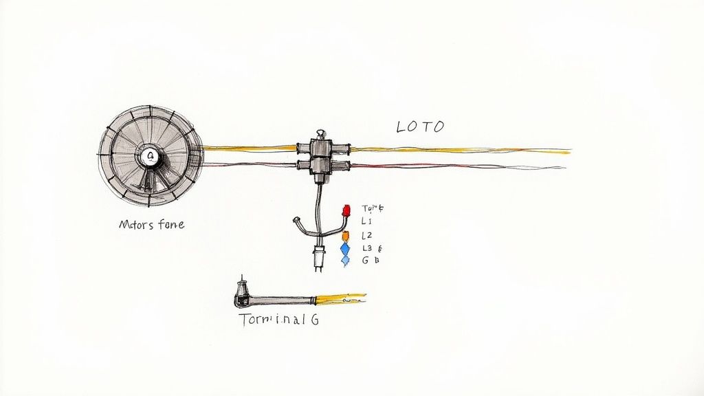
Before you even think about touching a wire, your first step is always Lockout/Tagout (LOTO). This is a hard-and-fast rule, no exceptions. De-energize the circuit, lock out the breaker or disconnect, and make sure you’re the only one holding the key.
Grounding and Conductor Sizing
A solid ground connection is what stands between you and a potentially lethal shock. If a fault occurs, the entire metal frame of the motor can become energized. That’s why you must always connect the green or bare copper ground wire to the grounding lug in the motor’s junction box, ensuring a clean, unbroken path back to the panel.
Next up is choosing the right size wire, or conductor. This isn't a place for guesswork. The wire gauge is determined by the motor's Full-Load Amps (FLA) listed on the nameplate and the rules laid out in the National Electrical Code (NEC). Using a wire that's too small is a recipe for disaster—it’ll overheat, the insulation will melt, and you’ve got a serious fire hazard on your hands.
Think about it this way: a motor with a 25A FLA that's 200 feet from the panel needs a beefier wire than the same motor located just 20 feet away. This is to compensate for voltage drop over distance. The NEC has tables that make this straightforward, helping you select the right conductor based on amperage, material (copper vs. aluminum), and insulation type.
Understanding Conductor Color Codes
Getting your phases mixed up can cause a motor to spin backward, which can be catastrophic for pumps, fans, and conveyors. Consistent color coding is your best tool for preventing this and for making any future troubleshooting much easier.
While you should always check local codes, a widely used standard for 480V three-phase systems in North America is:
Phase A: Brown
Phase B: Orange
Phase C: Yellow
Ground: Green, Green with a Yellow Stripe, or Bare Copper
For 208/230V systems, you'll more commonly find Black, Red, and Blue. The specific colors are less important than absolute consistency across your facility.
Remember this: Code compliance isn't just a hurdle to clear. It's about building a predictable system. Properly sized fuses and breakers are the designated "weak links"—they are meant to fail first to protect a motor that could cost thousands to replace.
Overload and Short-Circuit Protection
This is a point of confusion for many, but it's critical to get right. Every motor circuit needs two different kinds of protection.
Short-Circuit Protection: This is your circuit breaker or fuse. Its job is to react instantly to the massive inrush of current from a direct short or ground fault, preventing a fire or explosion. You size these based on NEC tables, not just the motor's FLA.
Overload Protection: This is usually a thermal overload relay inside the motor starter. It's designed with a time delay to ignore the brief current spike during startup. Its purpose is to protect the motor from sustained, lower-level overcurrents from things like a mechanical jam, which prevents the motor windings from cooking themselves.
Sizing these protective devices correctly is non-negotiable. In some cases, the rules for tapping conductors from a larger feeder can be complex. To do it safely, you need to follow strict guidelines, which you can learn more about by understanding the NEC tap rule.
Finally, don't forget the basics of making a solid physical connection. Use the right size lugs for your wires and torque them down to the manufacturer's spec. A loose connection is a hot connection. It creates resistance, which generates heat—enough to melt terminals and start a fire. A clean, tight, and properly torqued connection is the final step to a safe and reliable motor installation.
Testing and Troubleshooting Your Connections
All your connections are tight, the peckerhead cover is back on, and you’re ready to bring the machine to life. This is the moment of truth. But before you throw that main disconnect, a few quick verification checks will protect the motor and save you from a world of headaches.
Think of it as an engine builder checking the oil before the first startup. Sure, you could skip it and you might get lucky. But the risk of immediate, expensive damage just isn't worth it. Taking a few extra minutes here confirms you've executed the three phase motor wiring diagram perfectly.
Pre-Power-Up Verification Checks
Grab your multimeter. A couple of quick checks before applying power can catch a simple mistake before it becomes a catastrophic failure. These tests are all about confirming the integrity of your work and the motor's internal windings.
Continuity Check: Flip your meter to the continuity or resistance setting. Check the resistance between each of your phase terminals—T1 to T2, T2 to T3, and T1 to T3. The readings should be very low (just a few ohms) and, more importantly, almost identical across all three pairs. A perfectly balanced reading tells you the windings are good. An open line (infinite resistance) means you’ve got a broken winding or a loose connection somewhere.
Insulation Resistance Check: Now, grab a megohmmeter (you probably call it a "megger") to hunt for shorts. Test from each phase terminal to the motor's ground lug. You’re looking for a very high resistance reading, deep into the megaohms. This confirms that no windings are shorted to the motor's frame, which could cause a dangerous fault.
A crucial pre-start step is the "bump test." Make sure the motor is uncoupled from the gearbox, pump, or whatever it’s driving. Then, just briefly apply power—literally for a second—and kill it. Watch the shaft or cooling fan. If it's spinning the wrong way for your machine, kill and lock out the power immediately.
Reversing rotation is the easiest fix on the planet. Just swap any two of the three incoming power leads. For instance, swap the wires on L1 and L2. That’s it. This simple change reverses the phase sequence, which flips the direction of the motor's rotating magnetic field.
Common Troubleshooting Scenarios
Even the most seasoned electrician runs into issues. If you know what to look for, the symptoms will point you straight to the problem.
Motor Hums but Won't Start
This is the classic sign of a lost phase. The motor is getting some juice, enough to create a magnetic field that makes it hum, but it doesn't have the complete three-phase power it needs to start turning.
Check Your Supply: Start at the source. Use a voltmeter to verify you have the correct voltage across all three phases (L1 to L2, L2 to L3, L1 to L3).
Inspect Fuses & Breakers: A single blown fuse or a tripped pole on a three-pole breaker is a very common culprit.
Examine Connections: Get your eyes on the wiring. A loose connection at the starter, disconnect, or inside the motor's terminal box can easily cause you to drop a phase.
The smooth, powerful rotation of these motors comes from that nearly constant rotating magnetic field. This design innovation cut torque ripple down to about 15%, a massive leap from older single-phase designs that led to smoother and more productive machinery. You can find more on the history of 3-phase electricity at kathylovesphysics.com.
Overload Trips Immediately on Startup
If the overload relay trips the second you hit the start button, the motor is drawing way too much current. Something is seriously wrong.
Mechanical Jam: Before you blame the wiring, make sure the motor and its load can actually turn freely. A seized bearing, a jammed conveyor, or a clogged pump will cause an instant overload.
Incorrect Wiring: Go back and double-check your connections. A common mistake is wiring a dual-voltage motor for low voltage but connecting it to a high-voltage supply. This will create a massive inrush of current and trip the protection instantly.
Wrong Overload Setting: Check that the amp setting on the overload relay is properly matched to the motor's Full Load Amps (FLA) listed on the nameplate.
Common Questions from the Plant Floor
When you're staring at a three phase motor wiring diagram, a few questions always seem to come up. Whether you're a seasoned engineer or a new tech, getting these right is key to a safe, reliable installation. Let's walk through the ones I hear most often.
What Happens If You Wire a Three Phase Motor Incorrectly?
Getting the wiring wrong can range from a simple fix to a catastrophic failure.
The most common mistake is reversed rotation. If the motor spins the wrong way, don't panic. Just swap any two of the three phase leads—L1 and L2, for example. This flips the phase sequence and gets you spinning in the right direction. Easy.
A much bigger problem is mismatching the voltage. Say you wire a dual-voltage motor for its 230V setting but hook it up to a 460V supply. The result is a massive, almost instant current draw that will fry the windings beyond repair. Always, always double-check your connections against the diagram before you energize.
A word of caution on Wye-Delta starters: one wrong move here can create a dead short circuit between phases the second that timer transitions. This can trigger a dangerous arc flash, trip main breakers, and destroy contactors or the motor itself.
Can You Run a Three Phase Motor on Single Phase Power?
Technically, yes, but you can't just plug it in. You need a converter.
The best and most common way to do it is with a Variable Frequency Drive (VFD). A VFD is smart enough to take a single-phase input and electronically generate a perfectly balanced three-phase output. As a bonus, you get full speed control.
Other options exist, like a rotary phase converter, which uses an idler motor to generate that third leg of power. There are also static phase converters, which are simpler capacitor-based boxes, but be aware they typically cut the motor's horsepower by about a third. This makes them a no-go for heavy-load applications.
How Do You Identify Unmarked 9 Lead Motor Wires?
This is where things get tricky, but a good multimeter is your best friend.
First, you need to find the three separate winding circuits. Set your meter to continuity and start testing. You should find three distinct groups of three wires that are only connected to each other (for example, T1, T4, and T7 will show continuity, but not with any other wires).
Now for the hard part: figuring out which wire is which within a circuit (is this T1 or T4?). This requires a more advanced test involving a low DC voltage on one winding while you check for induced voltage and polarity on the others with a sensitive voltmeter. Honestly, this is a job for an experienced motor tech or a rewind shop.
For any motor control needs, from premium electric motors to custom UL-listed control panels, E & I Sales provides the expertise and equipment to ensure your projects are reliable and code-compliant. Find the right solution at https://eandisales.com.
Ever wondered how massive industrial machines can run with such precision and efficiency? In many cases, the secret lies in a Variable Speed Drive, or VSD.
So, what exactly is it? Think of a VSD as the accelerator pedal for an electric motor. Instead of flooring it and then slamming the brakes to manage speed, a VSD gives the motor just enough "gas" to match the exact demands of the job. This simple-yet-brilliant concept is a game-changer for industrial energy consumption.
What a Variable Speed Drive Does
At its heart, a Variable Speed Drive is an intelligent throttle for your motor. Before VSDs became common, the standard practice for controlling systems like pumps or fans was incredibly wasteful. You'd run the motor at 100% speed and then use a mechanical valve or damper to choke the output down to the level you needed.
It’s the industrial equivalent of driving your car with one foot on the gas—pushed to the floor—and the other on the brake to control your speed. It works, sure, but you’re burning through fuel and putting massive stress on your engine and brakes for no reason. A VSD gets rid of that entire wasteful process.
By perfectly matching the motor's speed to what the load actually requires, a VSD stops energy waste in its tracks. It delivers only the power needed for the task at hand, which can slash energy costs by 30-50% in the right applications.
Breaking Down VSD Functions
How does it pull this off? Instead of relying on crude mechanical dampers, a VSD intelligently adjusts the electrical power going into the motor. This gives you a far more sophisticated and efficient method of control, unlocking some major operational benefits.
Here’s a quick look at what a VSD brings to the table:
Function
Description
Practical Benefit
Speed Control
Varies the motor's rotational speed on demand—from a slow crawl to full tilt.
Match fan speed to cooling needs or adjust a pump to maintain precise pressure.
Soft Starting
Gently ramps the motor up to speed, eliminating the sudden power jolt of a direct start.
Reduces mechanical shock on belts, gears, and couplings, extending their lifespan.
Energy Savings
Draws only the power needed for the current load, especially at slower speeds.
Drastically cuts electricity bills for systems like pumps, fans, and compressors.
Process Optimization
Allows for fine-tuning system performance, leading to better product quality.
Get total control over conveyor speeds, mixer torque, or fluid flow rates.
From Brute Force to Finesse
To really get what a variable speed drive brings to the table, you have to look at the world it replaced. For decades, industrial motor control was a pretty blunt instrument. The go-to tool was the direct-on-line (DOL) starter, which was basically a big switch that slammed a motor from zero to full blast in an instant.
It was a simple and reliable method, but it was incredibly crude. There was no speed adjustment, just a massive mechanical shock to the motor and everything connected to it every single time it started. Think of it like a traffic light with only red and green—no yellow light to ease the transition, just jarring, abrupt stops and starts.
The Old Way: Mechanical Throttling
When a process needed less than full power, the "solution" was wildly inefficient. Engineers had no choice but to run the motor at 100% speed and then physically block the output to get the result they wanted.
This usually involved things like:
Valves: On a pump system, they'd just partially close a valve to restrict the flow of water.
Dampers: For a fan, they'd slide a damper into the ductwork to block the airflow.
This approach is profoundly wasteful. It’s like flooring the gas pedal in your car while riding the brake to control your speed. The engine is screaming, guzzling fuel, and all that power is just turned into useless heat by the brakes. For a long, long time, this was the accepted standard.
This constant-speed, mechanically throttled approach forced systems into a state of continuous conflict. It was a constant battle between the motor and the restriction, wasting incredible amounts of energy and accelerating wear on every single component.
The Shift to Smart Control
The glaring inefficiency of fixed-speed systems was a huge engineering problem that people chipped away at for decades. While early concepts for adjusting DC motor speed go back to the 1920s, the modern VSD era really kicked off in 1968 with the first commercial AC drive built with Silicon-Controlled Rectifiers (SCRs).
That breakthrough opened the floodgates. Microprocessors showed up in the 1970s, followed by the far more efficient IGBTs (Insulated-Gate Bipolar Transistors) in the 1980s, which made today’s compact, incredibly precise drives possible. To see just how far the technology has come, it's worth exploring the variable frequency drive market evolution and its key technological milestones.
This evolution was more than just new hardware; it was a complete change in thinking. Instead of overpowering a system and then choking it back, the VSD introduced the simple, elegant idea of giving the motor only the energy it needs to do the job at hand.
This move from fixed-speed to precision control finally solved a century-old problem, paving the way for the efficient, automated, and responsive industrial world we have today. The variable speed drive stopped being just a motor controller and became a cornerstone of modern industry.
How a Variable Speed Drive Actually Works
So, how does a VSD pull this off? It’s not just a fancy dimmer switch. A modern drive doesn't just restrict power; it completely rebuilds it from the ground up to give the motor exactly what it needs for a specific task.
The entire process happens in three quick steps. Think of it like a power-supply chain inside a single box: raw AC power comes in, gets converted and smoothed into stable DC, and then is rebuilt into a brand-new, fully controllable AC output.
The diagram below really shows the leap from older, energy-wasting motor control methods to the precision and efficiency we get with a VSD.
You can see how we moved past simply throttling a motor running at full tilt to a much smarter approach that saves energy and gives us total control.
Step 1: The Rectifier – Flipping AC to DC
The first thing that happens when utility power hits the drive is that it flows into the rectifier. Its only job is to take the incoming alternating current (AC) and turn it into direct current (DC).
AC power from the grid naturally flows back and forth in a sine wave. The rectifier, usually a set of six diodes, acts like a series of one-way electrical gates. It forces that alternating flow into a single direction, creating a rough, pulsating DC voltage. You have to start here because it’s much easier to manipulate DC power than to try and alter an AC frequency directly.
Step 2: The DC Bus – Smoothing Everything Out
That pulsating DC from the rectifier isn't clean enough to work with yet. It still has "ripples" left over from the original AC wave. This is where the DC Bus takes over.
Made up of large capacitors, the DC Bus works like a reservoir. It takes that bumpy DC voltage, stores it, and smooths it out into a stable, clean supply of DC power. Think of it as a shock absorber for electricity, ensuring the next stage has a perfectly steady source to draw from.
Without a clean, stable DC bus, the drive's output would be erratic, causing poor motor performance and even potential damage over time. This step is non-negotiable for reliable operation.
Now we have a perfect block of DC power, ready to be carved into whatever the motor needs.
Step 3: The Inverter – Building a New AC Wave
This is where the real control happens. The inverter takes that smooth DC power and, using incredibly fast switches, chops it up to build a brand-new AC waveform to send to the motor.
Inside the inverter are high-speed transistors (IGBTs) that can switch on and off thousands of times per second. By controlling the precise timing and duration of these switches, the drive creates a simulated AC sine wave at any frequency or voltage required. This technique is called Pulse Width Modulation (PWM).
Instead of a perfect, smooth curve, the VSD creates a series of square DC pulses with varying widths. The motor’s natural inductance smooths these rapid pulses out, interpreting them as a clean AC signal. This gives the VSD pinpoint control over the motor's speed and torque.
Of course, this high-frequency switching can create electrical noise (harmonics) that gets sent back into your electrical system. In many cases, it's worth looking into a harmonic filter for a VFD to keep your power clean and your other equipment happy.
By mastering this three-step process—rectify, smooth, invert—a VSD gives you complete authority over your motor, unlocking huge gains in process control and energy savings.
The Real-World Benefits of Using a VSD
It’s one thing to understand the theory behind a variable speed drive, but it's another thing entirely to see what it can do for your bottom line. Once you move past the technical specs, you find a powerful tool that unlocks some serious financial and operational wins. A VSD isn't just another motor controller; it's a strategic asset that pays you back in more ways than one.
The most obvious and immediate payoff is a massive drop in your energy bill. In most industrial plants, motor-driven systems are the biggest power hogs, often chewing up between 50-70% of the total electricity. VSDs go right for the jugular, cutting out the incredible waste you find in fixed-speed systems and delivering energy savings of up to 30-50%.
This is all thanks to a simple set of principles called the Affinity Laws, which are especially powerful for centrifugal equipment like pumps and fans. These laws highlight an incredible, almost magical relationship between speed and power.
For instance, dropping a fan's motor speed by a modest 20% doesn't just cut power by 20%. Instead, it slashes energy consumption by a jaw-dropping 49%. This is where the real money is saved—even small tweaks in speed can lead to huge savings.
Unlocking Massive Energy Savings
It’s no surprise the global VFD market is sitting at around USD 24.68 billion and is expected to hit USD 32.00 billion by 2030. With electricity costs soaring and a major push for efficiency, businesses are hunting for proven ways to cut their operating expenses, and VSDs are at the top of the list. You can see the full breakdown by checking out the latest VFD market trends from MarketsandMarkets.
By perfectly matching motor output to what the application actually needs right now, a VSD makes sure you aren't wasting a single kilowatt. Think about it: instead of running a pump at 100% and choking the flow with a valve, the drive just tells the motor to slow down. It’s an elegant solution that’s not just more efficient but is also a lot gentler on your whole system. To see how this works in the real world, you can learn more about how VFD energy savings are calculated in different industrial setups.
Smoother Operations and Tighter Process Control
Beyond the killer cost savings, a VSD gives you a level of control that old-school mechanical methods can't even touch. It lets you make incredibly fine-tuned adjustments to speed, torque, and pressure, which has a direct impact on your product quality and consistency.
Just look at these examples:
Conveyor Systems: A VSD can sync up multiple belts perfectly, stopping products from piling up, spilling, or getting damaged.
Industrial Mixers: It can tweak the motor torque on the fly as a material’s viscosity changes, guaranteeing a perfect blend every single time.
HVAC Fans: In a building's climate control, a VSD can adjust airflow smoothly to hold the perfect temperature, getting rid of those jarring on-off cycles of a fixed-speed motor.
This superior control makes your entire process more stable and reliable. By getting rid of sudden, jerky changes and allowing for smooth, gradual adjustments, VSDs help you run a much more predictable operation with way fewer headaches.
Reducing Mechanical Wear and Slashing Maintenance Costs
Here’s the benefit that often gets overlooked: a VSD can dramatically extend the life of your equipment. A traditional direct-on-line starter is just brutal on machinery. It slams the motor from zero to full speed in an instant, creating a huge current surge and a violent mechanical jolt.
That "whiplash" sends a shockwave through the entire system, putting stress on every single part connected to that motor. Do that over and over, and you’re just asking for premature failure of your most critical components.
A VSD changes the game completely by introducing soft starting. It gently ramps the motor up to speed, getting rid of that violent jolt. This one feature has a massive impact:
It drastically reduces stress on belts, gears, and couplings.
It protects the motor's windings from the thermal shock of high inrush current.
It minimizes pressure spikes in your piping, cutting the risk of leaks and bursts.
This gentler approach means fewer breakdowns, less unplanned downtime, and a serious reduction in maintenance bills. By taking care of your mechanical assets, a VSD delivers a powerful ROI that goes way beyond just your monthly power bill. It’s worth exploring the differences between predictive vs. preventive maintenance strategies to see how this fits into a bigger asset management plan.
VSD Benefits Breakdown: Energy Savings vs. Process Improvements
To put it all in perspective, here's a look at how VSDs deliver value across different applications, balancing the direct financial wins from energy savings with the crucial operational improvements they bring to the table.
Application Area
Primary Energy Saving Mechanism
Key Process Control Benefit
Mechanical Wear Reduction Impact
Pumps & Fans
Affinity Laws: Cubic power reduction with speed decrease.
Precise pressure/flow control without throttling valves.
High: Eliminates water hammer and pressure surges.
Conveyors
Matching speed to production throughput.
Smooth start/stop; synchronization of multiple lines.
High: Reduces stress on belts, chains, and gearboxes.
Mixers & Agitators
Adapting torque to material viscosity.
Consistent product quality; prevents motor overload.
Medium: Protects gearbox from shock loads.
Extruders
Holding precise speed under varying loads.
Tighter tolerances and improved end-product consistency.
Medium: Reduces wear on screws and barrels.
Ultimately, whether you're chasing lower energy bills or a more reliable production line, a VSD delivers on both fronts. The combined effect is what makes it such a fundamental piece of modern industrial automation.
Choosing the Right Type of VSD
Just like you wouldn't use a pickup truck for a Formula 1 race, not all VSDs are designed for the same job. Picking the wrong drive can lead to shaky performance, wasted money, or even damaged equipment. It's all about matching the right technology to the task at hand.
The world of variable speed drives really boils down to three main categories. Each offers a different level of performance and precision. Getting a handle on this hierarchy makes it much clearer which drive is the right fit for your application, whether you're just controlling simple airflow or choreographing complex robotic movements.
Standard Variable Frequency Drives (VFDs)
The most common and versatile type is the standard Variable Frequency Drive (VFD), which you’ll often hear called a scalar or V/Hz drive. Think of this as the reliable workhorse of the VSD family. It’s perfect for the vast majority of industrial applications where pinpoint-accurate torque control isn't the number one priority.
Its main job is to keep a constant ratio between voltage and frequency. This straightforward control method is incredibly effective for variable torque loads, where the muscle needed from the motor changes as the speed changes.
You’ll see standard VFDs everywhere, especially in applications like:
Pumps: Dialing in flow rates for water treatment or irrigation systems.
Fans: Controlling airflow in HVAC systems to manage building climates.
Blowers: Regulating air pressure for industrial drying or ventilation.
For these kinds of jobs, a VFD delivers fantastic energy savings and provides a gentle soft start, all without the cost and complexity of more advanced drives. It's the go-to solution for about 80% of all motor control needs out there.
Vector Control Drives
Now, when your application needs better torque control and a much quicker response, it’s time to step up to a Vector Control Drive. These drives are a whole lot smarter than standard VFDs. They run sophisticated algorithms and often use feedback to build a precise mathematical model of the motor's internal magnetic field.
This allows the drive to control the motor's speed and torque independently, giving you incredible precision even at very low—or even zero—speeds. Imagine a crane holding a heavy load perfectly steady; that requires powerful, unwavering torque, which is exactly where a vector drive shines.
A standard VFD just tells the motor how fast to spin. A vector control drive tells it how fast to spin and how hard to push, giving it the muscle to handle tough, constant-torque loads.
Key applications for vector control drives include:
Cranes and Hoists: Delivering the high starting torque needed to lift heavy loads off the ground.
Industrial Mixers: Keeping torque consistent even as the viscosity of the material changes.
Extruders: Maintaining exact speed under heavy and often fluctuating loads.
Vector drives come in two main flavors: open-loop (or sensorless), which offers great performance at a moderate cost, and closed-loop, which uses an encoder for feedback to achieve the highest degree of accuracy.
Servo Drives
At the absolute peak of the performance pyramid, you’ll find Servo Drives. If a standard VFD is a dependable family sedan and a vector drive is a heavy-duty truck, then a servo drive is a high-performance race car. It’s built for one thing: extreme precision and lightning-fast response.
Servo drives operate in a tightly managed closed-loop system, constantly processing high-resolution feedback from an encoder or resolver attached right to the motor. This allows the drive to make thousands of tiny adjustments every second, instantly correcting any deviation in position, velocity, or torque.
Their ability to execute exact, repeatable movements makes them indispensable for high-tech automation. They are the brains and the brawn behind applications that demand a level of accuracy other drives simply can't touch.
You'll find servo drives running:
Robotics: Enabling the smooth, precise motions of robotic arms on an assembly line.
CNC Machines: Guiding cutting tools with micron-level accuracy.
Automated Packaging: Ensuring products are placed and wrapped perfectly at incredible speeds.
Of course, this level of performance comes with a higher price tag. But for those critical applications where speed and accuracy are completely non-negotiable, servo drives are the only way to go.
Where You See VSDs in Action
Variable speed drives are the unsung heroes of the modern industrial world. They work quietly behind the scenes, making countless systems more efficient, reliable, and precise. Once you know what to look for, you’ll start seeing their impact everywhere—from the building you work in to the products you use every day.
Think of them as the invisible force optimizing the complex systems we often take for granted. By providing intelligent motor control, a VSD can solve nagging operational headaches and unlock serious savings in ways that old-school, fixed-speed methods never could.
Optimizing Commercial and Municipal Systems
Take a large commercial skyscraper. The heating, ventilation, and air conditioning (HVAC) system is a massive energy hog. A VSD installed on the building's fans and pumps can adjust airflow and water circulation in real-time based on occupancy and the temperature outside. This simple change can prevent millions in wasted energy costs every year.
It's a similar story in a municipal water treatment plant. VSDs are absolutely essential for managing the pressure in water mains by adjusting pump speeds. This prevents the dangerous pressure spikes that can burst aging pipes, saving cities from costly emergency repairs and service disruptions.
These applications reveal a core principle of using a VSD: matching output to real-time demand. Instead of running a motor at full blast and using a mechanical valve to throttle it down, the VSD simply slows the motor itself—achieving the same result with just a fraction of the energy.
Boosting Precision in Manufacturing
In the world of manufacturing, the precision offered by a variable speed drive is indispensable. Imagine a bottling plant where thousands of bottles fly down conveyor belts. VSDs synchronize the speed of multiple conveyor sections, ensuring a smooth, steady flow and preventing the kind of pile-ups that could shut down production and damage products.
This level of control is what separates a well-run facility from one that's constantly fighting fires. The ability to fine-tune motor speed directly impacts everything from product consistency to operational uptime. To get a better handle on how this all works, you can dig into the fundamentals of AC motor variable speed control and its applications.
Driving a Global Push for Efficiency
The adoption of VSDs isn't just a local trend; it's a worldwide phenomenon, driven by the dual needs of industrial growth and energy conservation. The Asia-Pacific region, for instance, leads the variable speed drive market, capturing about 40.9% of the global share. This growth is fueled by rapid industrialization and government initiatives focused on energy efficiency in countries like China, India, and Japan. You can discover more insights about this global VFD market growth on Precedence Research.
This trend is even pushing into emerging technologies. For example, VSDs are fundamental to the efficient power management required for the growing electrification of medium- and heavy-duty fleets. From skyscraper climate control to advanced manufacturing and logistics, the sheer versatility of the variable speed drive proves its value across nearly every industry shaping our modern lives.
Got Questions About VSDs? We've Got Answers.
When you start digging into Variable Speed Drives, a few key questions always seem to pop up. These are the practical, real-world concerns that can make or break a project. Let's tackle some of the most common ones we hear from the field.
Can I Slap a VSD on Any Old Motor?
Not exactly. While VSDs are the perfect partner for most standard three-phase AC induction motors, they aren't a one-size-fits-all solution. Trying to run a single-phase motor or a specialized synchronous reluctance motor on a standard drive will end in frustration. They need drives built specifically for them.
More importantly, you should always pair your drive with an inverter-duty rated motor. These motors are built tougher, with better insulation to handle the unique electrical stresses a VSD puts out. Skimping on this can lead to fried motor windings and a much shorter service life for your equipment.
When is a VSD Actually a Bad Idea?
Believe it or not, there are times when a VSD is the wrong tool for the job. If your application—say, a simple exhaust fan that always needs to run at maximum—is pegged at 100% speed, 100% of the time, a drive is overkill.
The magic of a VSD is its ability to save energy by matching motor speed to a changing load. If the load never changes, you get no savings. In fact, the drive itself uses a little power, making the system slightly less efficient than just starting the motor across the line.
Another red flag is an extremely dirty or dusty environment. The sensitive electronics inside a VSD can't handle being choked with debris. Without a proper, sealed enclosure, you're just asking for overheating and a premature failure.
Do I Need a Bigger Motor if I'm Using a VFD?
This is a great question, and the answer is often yes—or you need to make other adjustments. Think about it: the cooling fan on most motors is attached directly to the shaft. When you run the motor at a very low speed for a long time, that fan barely spins. It can't move enough air, and the motor starts to heat up.
To get around this, you have a couple of solid options:
Derate the motor: This just means you oversize it. You might use a 10 HP motor for a 7.5 HP load, giving you plenty of thermal headroom to keep things cool.
Add a separate blower: You can install a small, independently powered fan that provides constant airflow over the motor, no matter how slowly it's spinning.
Always check the manuals for both the motor and the drive. They'll give you the specific guidance you need to protect your investment and keep your system running safely within its thermal limits.
At E & I Sales, we live and breathe this stuff. If you're looking to boost your system's efficiency and control with the right motor and drive package, our team is here to help spec the perfect VSD and UL control panel for your needs. Contact us today to get started.
When most people think of "maintenance," they picture a technician with a wrench, fixing something that's already broken. But in the world of industrial operations, that's just a tiny piece of the puzzle. Real engineering maintenance is less about fixing and more about preventing.
More Than Just a Fix-It Crew
Think of it like the pit crew for a Formula 1 car. They aren't just waiting for a tire to blow out. They're constantly monitoring, tweaking, and swapping components to keep that machine screaming around the track at peak performance. That’s the essence of engineering maintenance services. It’s the strategic discipline of keeping your most critical assets—the heart of your operation—running like a Swiss watch.
This is the fundamental shift from a reactive, fire-fighting culture to a proactive, controlled one. Instead of scrambling when a critical motor grinds to a halt and brings your entire production line down, a smart maintenance strategy anticipates the failure before it ever happens. It’s about having experts who understand the intricate language of your machinery, from the subtle vibrations of a generator to the precise calibration of a control panel.
The Real-World Value of Maintenance
Let's be clear: investing in professional engineering maintenance isn't a cost center. It's a direct investment in your company's profitability and resilience. When you have a solid maintenance program in place, you're not just oiling gears; you're protecting your bottom line.
A well-executed strategy directly supports your core business goals:
Getting More from Your Assets: Expert care stops premature wear and tear in its tracks, squeezing every last drop of productive life out of your expensive equipment.
Keeping the Lights On: Proactive maintenance is the enemy of unplanned downtime. It keeps your lines running, your orders shipping, and your customers happy.
Protecting Your Profits: A single catastrophic failure can easily cost millions in lost production, emergency repair bills, and potential safety incidents. Good maintenance is your best insurance policy.
Keeping Your People Safe: There's no way around it—well-maintained equipment is safer equipment. This protects your team and keeps you on the right side of safety regulations.
This isn't just a niche idea; it's a massive, growing industry. The global maintenance services market is a powerhouse, valued at USD 81.86 billion and on track to hit USD 122.09 billion. That’s a 10.5% compound annual growth rate, driven by a global push for sustainability and the urgent need to keep aging infrastructure online. You can dive deeper into the maintenance services market report on researchandmarkets.com.
From massive manufacturing plants to sprawling energy facilities, every industry relies on these specialists to build a foundation of reliability and safety. This proactive mindset is what makes everything else possible, paving the way for the specific strategies we'll get into next.
The Four Core Maintenance Strategies You Need to Know
When it comes to keeping a facility running, there's no single magic bullet. Effective engineering maintenance isn't about a one-size-fits-all approach; it's about having the right tool for the right job. Think of it like taking care of your car—you don't treat a burnt-out headlight the same way you treat a weird noise coming from the engine.
A smart maintenance program blends different strategies to create a balanced, cost-effective plan that keeps the gears turning. Let's break down the four core approaches every plant manager should understand.
As you can see, the end goal is always the same: keep the operation running, get the most out of your equipment, and protect the bottom line. How we get there is where these strategies come into play.
1. Preventive Maintenance: The Scheduled Checkup
This is the one most people are familiar with. Preventive maintenance (PM) is all about routine, scheduled work designed to catch problems before they become catastrophes. It’s the industrial version of changing your car’s oil every 5,000 miles. You do it based on a calendar or a usage meter, not because something is actually wrong.
The triggers are simple: inspect a motor every quarter, or lubricate a bearing after every 1,000 hours of runtime. While it's a massive leap forward from just waiting for things to break, you do run the risk of performing unnecessary work on perfectly healthy components. A well-organized preventive maintenance schedule template is your best friend here, helping you map out and track every task.
2. Predictive Maintenance: The Smart Warning System
Now we're getting smarter. Predictive maintenance (PdM) is a condition-based strategy that relies on real-time data to tell you when a machine needs attention. Think of it as the check engine light on your dashboard—it warns you about low tire pressure before you end up with a flat on the side of the highway.
Using tools like vibration analysis, thermal imaging, and oil analysis, PdM lets technicians see a failure coming. This allows you to step in at the perfect moment—not too early, not too late. You get to maximize the life of your parts, slash maintenance costs, and dramatically reduce unplanned downtime. This data-driven approach is at the heart of modern engineering maintenance services.
3. Corrective Maintenance: The Necessary Fix
Let's be honest: sometimes, things just break. Corrective maintenance—also known as reactive maintenance—is the straightforward strategy of fixing something once it has failed. While it might sound like a plan for disaster, it actually has a strategic place in any good maintenance program.
You wouldn't schedule preventive maintenance for a lightbulb in the breakroom, would you? You just wait for it to burn out and then replace it. The same logic applies to non-critical, redundant, or low-cost assets where the consequence of failure is minimal. The trick is to apply this "run-to-failure" approach intentionally and not let it become the default for your critical machinery.
4. Shutdown Maintenance: The Planned Overhaul
This is the big one. Shutdown maintenance (or a turnaround) is when you take an entire plant or production line offline for a planned period of intensive, large-scale work. It’s like a full frame-off restoration of a classic car—an all-hands-on-deck effort to inspect, repair, and upgrade everything at once.
This strategy is reserved for complex jobs that are simply impossible to do while the plant is running. It demands military-grade planning and coordination to get everything done efficiently before bringing the whole system back online.
Each of these four strategies plays a crucial role. The best maintenance programs don't just pick one; they artfully combine all four based on equipment criticality, failure patterns, and cost.
Comparing Core Maintenance Strategies
To make it even clearer, here's a side-by-side look at how these four strategies stack up against each other.
Strategy Type
Trigger
Primary Goal
Example Application
Preventive
Time or Usage Schedule
Prevent failures before they occur
Quarterly inspection of an HVAC unit
Predictive
Real-time Condition Data
Intervene just before failure
Analyzing motor vibrations to detect bearing wear
Corrective
Equipment Failure
Restore functionality after a breakdown
Replacing a blown fuse on a control panel
Shutdown
Pre-planned Outage
Perform major overhauls and upgrades
Relining a blast furnace during a plant turnaround
As you can see, the trigger for action and the ultimate goal are what really set them apart. By understanding these differences, you can start building a maintenance program that ensures rock-solid reliability without wasting a dime—striking the perfect balance between proactive care and practical reality.
What a Maintenance Partner Actually Covers
So, we've talked strategy. Now, let's get down to the nuts and bolts. When you bring on an engineering maintenance partner, what are they actually doing on your facility floor? This isn't about vague promises; it's about a hands-on partnership designed to protect your most critical assets.
A good service agreement cuts through the fluff and focuses on the specialized electrical and mechanical systems that are the lifeblood of your operation. It’s about having an expert eye on the equipment that, if it goes down, grinds everything to a halt.
Let's pull back the curtain on what's typically covered.
Critical Care for Electric Motors
Think of electric motors as the workhorses of your plant. They run tirelessly, and you absolutely can't afford for them to quit. Maintaining them is a specialized craft.
Motor service goes way beyond a quick shot of grease. We're talking detailed inspections and diagnostics to catch things like bearing wear, insulation breakdown, or slight misalignments before they turn into a catastrophic failure that forces a costly rewind or a full replacement.
Servicing Motor Control Centers (MCCs)
If motors are the muscle, the Motor Control Center (MCC) is the brain. This is where you'll find the starters, variable frequency drives (VFDs), and programmable logic controllers (PLCs) that orchestrate your entire process.
An MCC is a dense, complex hub of electrical gear that needs serious attention. Ignoring it is like never checking the main breaker panel in your house—when something goes wrong here, it can take out an entire wing of your facility. That's why proper motor control center maintenance is non-negotiable for operational stability.
A poorly kept MCC isn't just an operational risk; it's a major safety hazard, with the potential for arc flash incidents. Regular service involves torquing connections, detailed cleaning, and using thermal imaging to find hot spots before they erupt.
Maintaining Custom UL Panels
Your custom UL-certified control panels are the bespoke brains behind specific machines or integrated systems. They’re engineered to run everything from complex automation sequences to critical safety interlocks.
Keeping these panels in top shape means ensuring every relay, breaker, terminal block, and power supply is working exactly as it was designed. This isn't just for reliability—it's essential for keeping the panel's UL listing valid, staying compliant, and guaranteeing the safety of the equipment it commands.
Low to Medium Voltage Switchgear Upkeep
Your switchgear is the gatekeeper of your entire electrical system. It's the first line of defense, protecting all your expensive downstream equipment from overloads and short circuits. It is, without a doubt, one of the most critical pieces of infrastructure you own.
A failure here isn't a minor hiccup. It can trigger a plant-wide blackout and create incredibly dangerous arc flash conditions. Professional engineering maintenance services for switchgear are your direct defense against these high-stakes disasters.
A solid switchgear service plan always includes:
Circuit Breaker Testing: Making sure the breakers will actually trip when they're supposed to.
Protective Relay Calibration: Verifying the "brains" of the gear are correctly set to spot problems.
Busbar Inspection and Cleaning: Preventing dangerous flashovers caused by dust, moisture, or loose connections.
These principles of electrical safety and uptime aren't confined to the factory floor. For a different perspective, this complete guide to EV charger servicing applies a similar logic to public infrastructure. In both worlds, the mission is the same: keep it safe, keep it running, and protect the investment. Once you understand what a true maintenance partner covers—from the motor to the main switchgear—you're in a much better position to know what your facility really needs.
How to Measure Maintenance Success and ROI
Spending on engineering maintenance shouldn't feel like a black box. How do you actually prove that the money you're putting in is a strategic investment and not just another line item on an expense report? The answer is simple: you track the right data and connect it directly to your bottom line.
Vague feelings about "things running better" won't convince a CFO. To justify and optimize your maintenance budget, you have to speak the language of numbers. This means adopting Key Performance Indicators (KPIs) that turn maintenance activities into clear, measurable outcomes that directly impact profitability.
It’s this shift in perspective that's crucial for showing real value and securing ongoing support for your maintenance programs.
Key Metrics That Tell the Real Story
You don't need dozens of complex formulas to get started. A handful of core KPIs can give you a powerful snapshot of how effective your maintenance program really is. Think of them as the vital signs for your plant's health.
Two of the most fundamental metrics are:
Mean Time Between Failures (MTBF): This is the average time a piece of equipment runs smoothly before it breaks down. A higher MTBF is a crystal-clear sign of improved reliability.
Mean Time To Repair (MTTR): This tracks the average time it takes to get failed equipment back online, from the moment it stops to the moment it's running again. A lower MTTR reflects a more efficient maintenance operation.
Let's put that into perspective. Imagine a critical bottling line conveyor. If its MTBF jumps from 500 hours to 1,500 hours, you’ve just tripled its reliability and slashed production interruptions. If your team also cuts its MTTR from four hours down to one, you're back in business that much faster when a failure does happen.
By focusing on improving just these two numbers, you create a powerful ripple effect. Higher reliability (MTBF) and faster recovery (MTTR) directly translate into more uptime, higher output, and increased revenue.
Calculating the True Return on Investment
Beyond the day-to-day operational metrics, the ultimate measure of success is Return on Investment (ROI). This calculation ties your maintenance spending to tangible financial gains, making the value proposition impossible to ignore.
The ROI formula for maintenance is pretty straightforward:
(Financial Gain from Maintenance – Cost of Maintenance) / Cost of Maintenance
The real trick is accurately calculating the "Financial Gain." This isn’t just about the money you saved on a specific repair; it’s about the massive cost of the downtime you prevented.
Think about this scenario:
A predictive maintenance program costs you $50,000 for the year.
This program helps your team spot a failing gearbox on the main production line before it completely seizes up.
An unexpected failure of that gearbox would have caused 48 hours of downtime, costing $10,000 per hour in lost revenue—that’s a $480,000 loss.
In this case, your $50,000 investment prevented a disaster worth nearly half a million dollars. The ROI is massive, proving that proactive maintenance isn't a cost center; it's a high-yield investment. This financial reality is driving huge growth, with the maintenance and support segment projected to hit USD 753.5 million. In North America, companies are already cutting unplanned downtime by 30-40% by outsourcing maintenance and using predictive analytics. You can dig into more of these engineering services market trends on grandviewresearch.com.
Building a Culture of Measurement
Putting KPIs in place is more than just a technical exercise—it’s a cultural shift. It means getting serious about collecting data consistently, reporting it clearly, and committing to using those insights to get better every day.
Start by getting a baseline for your most critical assets. Once you know where you stand, you can set realistic targets for improvement and track your progress. This data-driven approach is what transforms maintenance from a necessary evil into a strategic driver of operational excellence and, ultimately, profitability.
Choosing the Right Engineering Maintenance Partner
Picking an engineering maintenance services partner is one of the biggest calls an operations manager has to make. This isn't just about getting someone to fix what’s broken. You're building a strategic relationship that has a direct line to your plant's safety, uptime, and bottom line.
The right partner feels like a natural extension of your own team. The wrong one? They can become a constant source of risk, inefficiency, and headaches. You need to look past the price tag and take a methodical approach to find a provider who truly gets your operation and shares your commitment to safety.
Do They Have the Right Kind of Experience?
First things first, your partner needs to have serious technical chops in your specific world. A team that excels in food and beverage processing understands sanitary standards and the relentless pace of production in a way that an oil and gas specialist simply won't.
Don't be shy about asking for proof. Request case studies or, even better, references from companies that look a lot like yours. You're looking for verifiable expertise—certified technicians and engineers who know their way around everything from your medium voltage switchgear to the PLCs running your lines. As facility owners know, a partner who can work with your existing digital tools is a huge plus, which is why integrating BIM for owners in maintenance planning has become such a critical conversation.
Often, the best partners go beyond just repairs. They can act as an effective industrial automation system integrator, helping you find new ways to improve your entire process.
A Rock-Solid Safety Record Isn't Negotiable
In our world, safety is everything. A provider's safety record is a crystal-clear indicator of their discipline and professionalism. It tells you exactly how they’ll operate when they’re on your floor.
Here’s what to look for:
Experience Modification Rate (EMR): An EMR under 1.0 is the gold standard. It shows they are statistically safer than the industry average.
OSHA Compliance: Ask them directly about their history of OSHA recordable incidents and the safety programs they have in place.
Technician Training: How do they train their people? Dig into their safety protocols, certifications, and what they do for ongoing education.
A partner with a stellar safety record isn't just protecting their own crew. They're protecting your people, your equipment, and your business from liability and disaster.
Understanding the Money: Comparing Pricing Models
You need to know how a potential partner bills so you can budget properly and make sure you're getting real value. It usually comes down to two main approaches.
1. Fixed-Fee Contracts You pay one set price for a clearly defined list of services over an agreed-upon time. This model gives you predictable costs, which is perfect for routine preventive maintenance schedules where there are few surprises.
2. Time-and-Materials (T&M) Contracts With T&M, you're billed for the actual hours worked plus the cost of any parts or materials used. It’s a flexible model that works well for unpredictable corrective maintenance jobs or special projects where it's tough to nail down the full scope from the start.
The global engineering services market is huge, valued at around $2.0 trillion. This is driven by all sorts of regional needs, like the push in North America for energy-efficient retrofits to cut operational risks. Getting the pricing model right is your first step in tapping into these services effectively.
Your Engineering Maintenance Questions Answered
Diving into industrial upkeep always stirs up a few questions. Picking the right strategy—or the right partner—for your engineering maintenance services is a big deal, and you need straight answers. Let's tackle some of the most common questions we hear from plant managers and engineers to give you that clarity.
What Is the Difference Between Facility Maintenance and Engineering Maintenance?
It’s easy to lump all maintenance into one bucket, but they’re two completely different animals.
Think of it this way: facility maintenance takes care of the building itself. Engineering maintenance takes care of the highly specialized production equipment inside that building.
Facility Maintenance is all about the building’s core infrastructure. We're talking HVAC repairs, plumbing, lighting, and general structural work needed to keep the place safe and comfortable.
Engineering Maintenance, on the other hand, is laser-focused on the complex machinery that actually makes your product. This means servicing things like electric motors, custom UL control panels, and medium-voltage switchgear—assets that demand certified engineering know-how to handle safely.
One keeps the roof over your head, and the other keeps your production lines moving.
The distinction is critical. Your facility tech can fix a leaky pipe, but only a qualified maintenance engineer can properly diagnose and service the variable frequency drive running your main conveyor system.
How Can a Small Business Afford Comprehensive Maintenance Services?
If you're running a smaller operation, a full-blown maintenance contract can sound like a budget-buster. But you don't need an all-or-nothing plan to get real results. Smart, targeted strategies make professional maintenance totally accessible.
The best place to start? Identify your most critical assets. Pinpoint the handful of machines that would cause the most financial pain if they went down. From there, you can build a focused preventive maintenance plan just for that high-priority equipment. It's a surgical approach that delivers the most bang for your buck.
Another great option is a retainer-based contract for corrective maintenance. This gives you an expert on-call when you need one most, without the overhead of a full-time, in-house team. It's a model that gives you peace of mind and scales right alongside your business, offering a practical path to better reliability.
What Role Do AI and IoT Play in Modern Maintenance?
This isn't just hype. Artificial Intelligence (AI) and the Internet of Things (IoT) are completely changing the maintenance playbook. They’re helping us shift from being reactive to being predictive, giving teams the power to stop failures before they ever happen. It’s a massive leap forward.
IoT sensors are like a 24/7 health monitor for your equipment. You place them on motors, pumps, and other critical assets, and they constantly collect real-time data on vibration, temperature, and energy use. This firehose of information is where AI steps in.
AI algorithms chew through all that data, spotting subtle patterns a human could never see. The system can then predict when a part is likely to fail, giving you a heads-up weeks or even months in advance. This move to condition-based maintenance is just incredibly efficient—it gets rid of unnecessary scheduled work and helps you squeeze every bit of productive life out of your most important assets.
At E & I Sales, we know that reliable equipment is the backbone of your operation. We bring the expert support, custom control solutions, and deep product knowledge you need to keep your facility running at its absolute best. Let's build a more reliable future for your plant together.