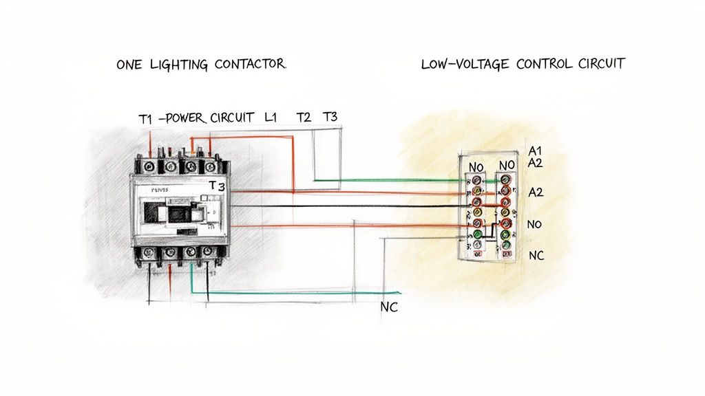
Before you even think about stripping a wire, grabbing your schematic is the most important thing you'll do. A wiring diagram for lighting contactors is your roadmap, and it clearly separates the high-voltage power side from the low-voltage control side. Getting this right isn't just good practice—it's what keeps the system safe and makes troubleshooting a breeze later on.
Reading and Understanding Your Wiring Diagram
Think of the wiring diagram as the blueprint for your whole lighting setup. It’s a visual guide to the two different jobs happening inside that contactor: the power circuit, which handles the heavy lifting, and the control circuit, which is the brains of the operation.
It's a classic rookie mistake to mix these two up, and that can lead to fried components or, worse, a dangerous situation. Learning to read this map correctly from the start means you can walk up to any standard schematic and know exactly how to turn it into a real-world, working installation.
Identifying Key Terminals and Symbols
First thing's first, let's get familiar with the key players you'll see on almost any diagram. Every schematic will label these main connection points.
Power Terminals (L1, L2, L3): This is where your high-voltage power comes in from the breaker panel.
Load Terminals (T1, T2, T3): This is the "out" side, where power heads off to the light fixtures.
Coil Connections (A1, A2): Here's the heart of the control circuit. When the right low voltage hits these terminals, the electromagnet pulls in, and the main contacts close.
Auxiliary Contacts (NO/NC): These are small, low-power contacts. They aren't for the main lights; instead, they're used for things like sending a status signal to a control panel or preventing another piece of equipment from turning on.
The absolute most critical concept to grasp is the separation between power (L1-L3 to T1-T3) and control (A1-A2). This is what allows a tiny, safe signal—like from a 24V timer—to safely command a powerful 480V circuit without the two ever crossing paths.
Decoding Power and Control Paths
On the diagram, you'll notice the power circuit is usually drawn with thicker lines. This represents the beefier wire needed to handle the current your lights will draw. The path is dead simple: power comes in at L1, L2, and L3, waits at the open contacts, and then flows out through T1, T2, and T3 as soon as the contactor pulls in. The basic principle is very similar to what you’d see in other heavy-duty applications; you can see more examples in our guide to the three-phase motor wiring diagram.
The control circuit, on the other hand, is shown with thinner lines. This is the path that connects your switch, timer, or occupancy sensor to the A1 and A2 coil terminals. Its only job is to tell the contactor when to energize.
When you look at the specs, it’s clear these devices are built to last. A typical lighting contactor is rated for 1 million mechanical operations and can handle 100,000 electrical cycles at its full rated load. The diagram is what shows you how to properly isolate those heavy-duty power circuits from the delicate control logic, ensuring a long and reliable service life.
Time to get our hands dirty with the high-voltage side of things. This is where the real power—the juice that actually runs your lights—gets hooked up to the contactor. We're aiming for clean, secure connections that will safely carry the load for the long haul.
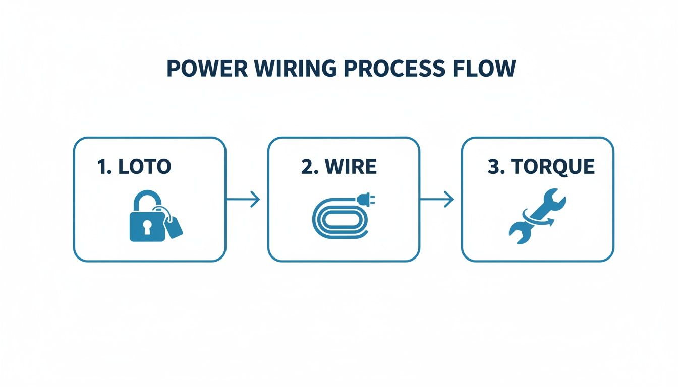
But before you even think about touching a wire, let’s talk about the single most important step: Lockout/Tagout (LOTO). Seriously. Kill the power at the breaker, slap your lock and tag on it, and then double-check with your multimeter to make sure it's truly dead. This isn't optional; it's what separates professionals from amateurs and keeps you safe.
Connecting Three-Phase Power
In most commercial or industrial spaces, you'll be dealing with three-phase power. It’s the standard for balancing heavy electrical loads across a facility. Looking at your contactor, you’ll see the power terminals clearly marked.
Supply Side: Your incoming power conductors (often black, red, and blue) will land on the terminals marked L1, L2, and L3.
Load Side: The wires heading out to your light fixtures connect to the corresponding terminals labeled T1, T2, and T3.
It's a simple, direct path. Power comes in on the "L" side, waits for the coil to pull the contacts closed, and then flows out the "T" side to the load.
One of the biggest mistakes I see in the field is undersized wire. It’s a ticking time bomb. Wires that are too small for the amperage they're carrying will overheat and can easily start a fire. If you're ever in doubt, use a good set of electrical calculation tools to confirm the right wire gauge for your specific load and distance. Don't guess.
Handling Single-Phase Connections
What if you're working in a smaller area or on a system that uses single-phase power? No problem. The concept is identical, just with fewer wires to manage.
You’ll have a single hot (line) wire and a neutral. You'll just use two of the contactor's poles. A common way to do this is to land the incoming hot on L1 and the neutral on L2. The outgoing hot wire to your lights then connects to T1, and the outgoing neutral connects to T2. Simple as that.
A Pro Tip on Terminations: Get yourself a calibrated torque screwdriver. It’s a game-changer. Over-tightening a terminal lug can be just as bad as leaving it too loose—you can damage the equipment or create a high-resistance hot spot. Check the manufacturer’s spec sheet for the proper torque values and hit them every time.
To help visualize the key differences, here's a quick breakdown of what to keep in mind for each system.
Power Wiring Quick Reference for Lighting Contactors
Parameter
Single-Phase System
Three-Phase System
Incoming Wires
Typically one hot (line) and one neutral.
Three hot conductors (e.g., L1, L2, L3).
Contactor Poles Used
Usually two poles are sufficient (one for hot, one for neutral).
Requires a contactor with at least three poles.
Voltage
Common voltages are 120V or 277V.
Common voltages include 208V, 240V, or 480V.
Load Balancing
Not a primary concern as it's a single circuit.
Critical for distributing the lighting load evenly across the building's electrical service.
Typical Use Case
Smaller commercial spaces, residential applications, or specific zones.
Industrial facilities, large commercial buildings, and high-power lighting arrays.
Ultimately, whether you're wiring a simple single-phase circuit or a complex three-phase system, the fundamentals of good workmanship apply.
And remember, your PPE is non-negotiable. At the very least, have your safety glasses and properly rated gloves on. Taking a few extra moments to be methodical and safe is what turns a potentially dangerous job into just another professional installation.
Designing and Wiring Your Control Circuit
Alright, this is where the magic happens. The power wiring is the muscle, but the control circuit is the brain of the whole operation. This is what turns a simple box of parts into a smart switching system that knows exactly when to turn those high-power lights on and off.
Getting this part right is what separates a reliable, automated lighting setup from one that's a constant headache. We're moving past a basic light switch on the wall and into the real-world control schemes you'll actually find on the job. The entire goal is to send a signal to the contactor's coil—you'll see it marked A1 and A2—at just the right moment.
From Simple Switches to Smarter Setups
The most basic setup you can have is a simple maintained switch. Flip it one way, power flows to the coil (A1), the contactor pulls in, and the lights come on. Flip it the other way, power is cut, and everything goes dark. Simple.
But in any modern industrial or commercial space, you need more than that. Let’s look at some of the most common and practical upgrades I've wired in over the years:
Timers for Scheduled Lighting: This is a classic. You wire an industrial timer into the control circuit to handle lighting for specific shifts or business hours. The timer's contacts act as the switch, automatically energizing the contactor coil based on whatever schedule you program.
Photoelectric Sensors for Dusk-to-Dawn Control: For any outdoor or perimeter lighting, a photocell is your best friend. Instead of a switch, you wire the sensor's output to the A1 terminal. When the sun goes down, the photocell sends the signal. When the sun comes up, it cuts it. It's set-it-and-forget-it control.
Pilot Lights for Status Indication: How do you know if the lights 500 feet away are actually on? You add a normally open (NO) auxiliary contact to the side of your contactor. When the main contactor pulls in, this little auxiliary contact closes, sending power to a small indicator light on your panel door. It's a quick, at-a-glance confirmation that the system is working.
This workflow isn't just a suggestion; it's the professional standard. Safely isolating power, making clean connections, and torquing everything down is non-negotiable.
Matching the Coil Voltage Is Non-Negotiable
Here’s a detail that trips up a surprising number of people: selecting the right coil voltage. This has absolutely nothing to do with the big 480V or 208V power running through the main contacts (L1/T1, etc.). You have to match the coil to your control power source.
A mismatched coil is a recipe for instant failure. If you send 120VAC to a 24VDC coil, you'll hear a pop and smell smoke—it’s toast. Send 24VDC to a 120VAC coil, and you'll get… nothing. Always, always double-check the voltage printed right on the contactor's coil itself.
You’ll typically run into a few common coil voltages:
120VAC: Very common. It's usually pulled from a small control transformer inside the panel.
24VAC/DC: The go-to standard for PLCs and most modern automation controls.
277VAC: You'll see this when the control power is tapped directly from one leg of a 480/277V lighting circuit.
Lighting contactors are the unsung heroes in big facilities like warehouses, retail stores, and office buildings. In these applications, latching-type contactors are becoming incredibly popular because they can slash coil power consumption by up to 95%. They only need a quick electrical pulse to switch on or off, making them ideal for energy-conscious designs.
Figuring out these control schemes is a fundamental skill. For a much broader look at how this fits into the bigger picture, check out our guide on industrial control panel design. This is where your wiring diagram for lighting contactors becomes a critical piece of a much larger, more sophisticated automation strategy.
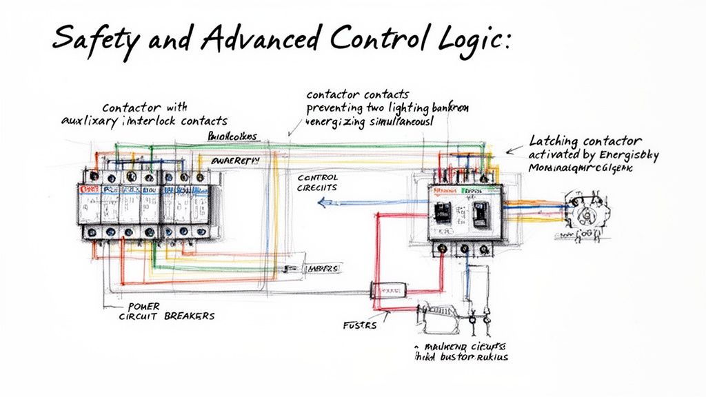
Going Beyond the Basics: Safety and Advanced Control
A truly professional installation does more than just switch the lights on and off. It's about building in layers of safety and intelligent control. This means getting serious about protecting both the high-voltage power circuit and the more delicate control circuit. Before you can even think about advanced logic, you have to get the protection right.
That starts with properly sized fuses or circuit breakers. You need separate protection for the main power lines feeding the lights and for the low-voltage control wiring. A short in a simple toggle switch shouldn't ever be able to take down an entire lighting panel, and a small, dedicated fuse on the control side is what prevents that from happening.
Creating Hardwired Safety Interlocks
Once your circuits are properly protected, you can start using the contactor itself to add some smarts. Those little auxiliary contacts—the NO (Normally Open) and NC (Normally Closed) terminals—are your best friends for creating bulletproof safety interlocks.
Let's say you have two banks of high-bay lights that should absolutely never be on at the same time. Easy. You wire the control signal for the second contactor through an NC auxiliary contact on the first one. This creates a simple, physically enforced logic: if Contactor #1 is energized, its NC contact opens up, cutting off the path for the signal to ever reach Contactor #2.
This kind of hardwired interlock is infinitely more reliable than relying on a PLC or smart relay programming alone. It’s a fundamental concept in machine safety for a reason—it just works.
A critical part of any safety design is accounting for all potential failure modes. This includes ensuring your system is resilient against electrical faults. For a deeper understanding of this topic, you can find valuable information in our detailed guide on ground fault protection.
Wiring Latching Contactors for Big Energy Savings
For large facilities where the electric bill is a constant concern, the latching contactor is a total game-changer. You might also hear it called a mechanically held contactor. Unlike a standard contactor that needs constant power flowing through its coil to stay closed, a latching contactor works differently.
It has two separate coils: one to "latch" (close the main contacts) and another to "unlatch" (pop them open). The beauty is that each coil only needs a quick, momentary pulse of power to do its job.
To turn lights ON: You hit the "LATCH" coil with a brief signal. A mechanism inside the contactor closes the contacts and physically locks them into place. The coil can then de-energize completely.
To turn lights OFF: You send another momentary signal, this time to the "UNLATCH" coil, which releases the mechanical lock.
This design slashes energy consumption because there's no continuous current draw. As a bonus, it also gets rid of that annoying hum you often hear from standard AC contactors.
When you're designing any control circuit, especially for critical systems, it pays to think through every angle of safety and reliability. For example, reviewing the fire safety guidelines for emergency lighting shows how specialized systems build in their own unique protections. The core principles are the same, though, making your wiring diagram for lighting contactors the single most important document for proving the system is built right.
Commissioning Your System Like a Professional
Just because you've landed the last wire doesn't mean the job is done. The final, critical step is commissioning—this is what separates a truly professional installation from one that’s just functional. It’s where you meticulously verify every single connection and function before a single watt of load power flows through it.
Think of it as a pre-flight checklist for your electrical system. Skipping this part is just asking for trouble, whether it's immediate equipment failure, a frustrating callback, or a dangerous fault. A few extra minutes of methodical checking here will save you hours of headaches later.
The Essential Pre-Power Checklist
With the main breaker locked out and tagged, it's time to go point-to-point. This isn't just a quick once-over; it's a systematic hunt for any mistakes made during the install.
Continuity Checks: Get your multimeter out and put it on the continuity setting. Does your switch actually complete the circuit to the A1 terminal? Do you have a solid, unbroken path from the T1 terminal all the way to that first light fixture? Ring out every single wire.
Torque Verification: Grab your calibrated torque screwdriver. Go back and check every single terminal—power and control. I can't tell you how many failures I've seen traced back to a loose connection that created a hot spot.
Control Device Function: Manually activate everything. Push the override button, put your hand over the photocell, and spin the dial on the timer. Make sure each physical action does exactly what it's supposed to do at the control terminals.
The real mark of a pro is in the details. Clean, organized wireways don't just look good—they improve airflow and make future troubleshooting a whole lot safer and easier for the next person in that panel. Tidy wiring is a sign of true craftsmanship.
Final Touches and Documentation
After you've confirmed the wiring is rock solid, it's time for the final piece: labeling. Every control wire needs a clear, unique identifier on both ends. It might seem tedious, but it transforms future maintenance from a guessing game into a straightforward task.
Lighting contactors have been the backbone of industrial control for decades, and they've evolved right along with the technology. Older workhorse models, like ABB's CR463L series, were incredibly versatile, offering up to 74 different circuit combinations and handling anything from 120V to 600V AC.
This history, carried on by trusted distributors like E & I Sales since 1974, is built on the importance of getting the wiring exactly right. The diagrams for those classic units even included clever safety indicators, like a button that physically protruded when the contacts were closed. It’s a great reminder of how valuable clear, physical verification is—a principle that's just as crucial today. You can learn more about these advanced contactor specifications to see how the technology has grown.
Common Questions We Hear in the Field
Even with the best wiring diagram taped to the panel door, some questions always seem to come up on the job. Let’s walk through a few of the most common ones I hear from technicians to clear up the confusion and help you sidestep those little issues that can turn into big headaches.
Getting these details right is what separates an installation that just "works" from one that's dead reliable for years to come. It’s about knowing the why behind the wiring.
Lighting Contactor vs. Motor Contactor
So, what’s the real difference between a lighting contactor and a motor contactor? They look practically the same, but they're built for completely different battles.
Lighting contactors are specifically beefed up to handle the massive inrush current you get when you energize a huge bank of fluorescent or LED lights. That initial surge can be absolutely brutal—many, many times the normal running current. A motor contactor, on the other hand, is designed to handle the sustained inductive loads from a motor.
You'll notice lighting contactors are rated in amps, with no horsepower (HP) rating in sight. If you try to use a standard motor contactor for a big lighting load, you're asking for trouble. Sooner or later, those repeated inrush spikes will weld the contacts shut.
Why Is My Contactor Buzzing So Loud?
A loud, angry hum or buzz from a contactor is its way of screaming for help. Don't ignore it. Nine times out of ten, the problem is with the coil or the magnetic core that pulls the contacts closed.
Here are the usual suspects:
Low Control Voltage: The coil isn't getting enough juice to pull the magnet in tightly.
Junk in the Magnet: A tiny bit of dust, metal shaving, or grime is stuck between the faces of the magnet.
Broken Shading Ring: On an AC contactor, this little copper ring is critical for preventing chatter. If it cracks or breaks, the buzzing starts.
First thing's first: grab your meter and check the control voltage right at the coil terminals. If that's good, lock out the circuit, and give the magnet faces a careful inspection and cleaning. A chattering buzz is often the last gasp of a dying contactor.
One of the most common service calls is for a buzzing contactor. Before you even think about ordering a replacement, kill the power, lock it out, and just wipe down the magnetic surfaces with a clean, dry rag. More than half the time, that's all it takes. It's a five-minute fix that can save you a ton of hassle.
Can You Mix and Match Power and Control Voltages?
"Can I control a three-phase contactor with single-phase power?" Absolutely. In fact, this is how it's done in almost every industrial plant you'll ever walk into.
The power circuit (the high-voltage side switching the load) and the control circuit (the low-voltage side with the coil) are two totally separate things. They're electrically isolated from each other inside the contactor.
The voltage on the coil has nothing to do with the voltage on the load. You can easily have a contactor switching a 480V three-phase lighting circuit that's being controlled by a 120VAC signal from a timer, or even a 24VDC signal from a PLC. The key is just to order a contactor with a coil that matches your control voltage.
At E & I Sales, we live and breathe this stuff. We provide the heavy-duty components and practical advice you need for complex industrial jobs. From motor controls to custom UL-listed panels, we help you build systems that are safe, bulletproof, and efficient. See how our experience can back up your next project at https://eandisales.com.
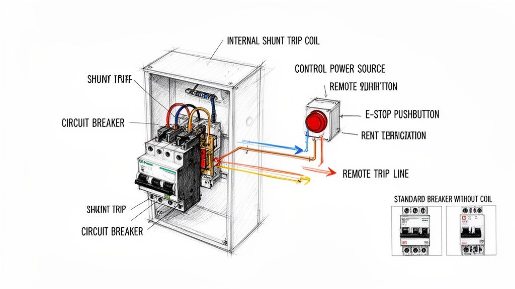
At its core, a wiring diagram for a shunt trip circuit breaker is pretty straightforward. It shows an internal coil wired up to a remote device, which could be anything from an E-stop button to a fire alarm contact.
When that remote device closes the circuit, it shoots a control voltage to the coil. That coil then mechanically forces the breaker to open instantly, cutting power from a safe distance. This is a whole different ballgame compared to a standard breaker, which just sits there waiting to react to overcurrent. With a shunt trip, you're in control.
What a Shunt Trip Circuit Breaker Actually Does
Before you start tracing wires, it's crucial to get why a shunt trip breaker is an absolute non-negotiable in so many industrial safety systems. A standard thermal-magnetic breaker is passive—it only trips after an overcurrent or short circuit has already happened. A shunt trip breaker, on the other hand, acts on command. It gives you a way to kill a circuit immediately and remotely, making it a cornerstone of modern safety protocols.
Think of it as the electrical world's emergency brake. A regular breaker protects the equipment; a shunt trip protects your people and your facility. You'll see them everywhere, from machine shops to complex automated lines. In high-risk fields like those you find in metal fabrication companies, the ability to stop heavy machinery instantly isn't just a feature—it's a necessity.
The Key Players in a Shunt Trip System
A shunt trip system is really quite simple when you break it down. You’ve just got four main parts working together. Understanding how they interact is the first step to getting the installation right.
The Circuit Breaker: This is your main device. It has all the standard overcurrent protection but includes an internal port for the shunt trip accessory.
The Shunt Trip Coil: It's a small solenoid coil that lives inside the breaker. When it gets hit with voltage, it creates a magnetic field that physically shoves the breaker's trip mechanism open.
The Control Power Source: This is a separate, dedicated power source that supplies the juice—like 24V DC or 120V AC—to activate the coil. It has to be reliable and sized correctly for the job.
The Initiating Device: This is your trigger. It's usually a normally open (N.O.) contact, like an emergency pushbutton, a relay from a fire alarm panel, or even an output from a PLC.
Shunt Trip vs. The Other Guys
It's easy to get shunt trips, standard breakers, and undervoltage release breakers mixed up. But getting their functions straight is critical if you want to apply and wire them correctly.
A standard breaker is completely passive. It only cares about what’s happening on the main circuit it's protecting and has no external control inputs.
An undervoltage release (UVR) breaker is the exact opposite of a shunt trip. It needs a continuous control voltage just to stay closed and will automatically trip if that voltage is lost. We use these when we don't want a machine to suddenly restart after a power outage.
A shunt trip breaker, however, stays closed until a control voltage is applied to its coil. It’s a "trip on command" device, making it perfect for E-stop circuits where you need deliberate action to cut the power.
Choosing the right coil voltage is a common decision point when designing a control panel. It depends entirely on your control system's standard voltage.
Shunt Trip Coil Voltage Selection for Common Applications
Coil Voltage
Typical Control Source
Common Industrial Applications
Key Design Consideration
24V DC
PLC Outputs, Safety Relays, Low-Voltage Control Circuits
Automated machinery, robotics, UL508A control panels
Most common for modern control systems; minimizes shock hazard in the control cabinet.
120V AC
Control Transformers, Lighting Circuits, Fire Alarm Panels
Building automation, HVAC systems, simpler machine controls
Widely available and simple to source, but requires careful routing of AC control wiring.
240V AC
Direct Line Voltage Tap (Phase-to-Phase or Phase-to-Neutral)
Heavy industrial equipment, motor control centers (MCCs)
Can simplify wiring by eliminating a control transformer, but introduces higher voltage into the control circuit.
48V DC
Telecom Power Supplies, Battery Backup Systems
Telecommunications facilities, data centers, substations
Common in DC-powered environments; ensures trip functionality during AC power loss if on a UPS.
This choice impacts everything from wire sizing to panel layout, so getting it right upfront saves a lot of headaches later.
This foundational knowledge is key for any plant engineer or system integrator trying to build a reliable and code-compliant UL control panel. Being able to remotely and decisively kill power isn't just a nice-to-have; it's a critical safety function. If you're working with specific brands, digging into the features of an ABB circuit breaker and its available accessories is a great next step.
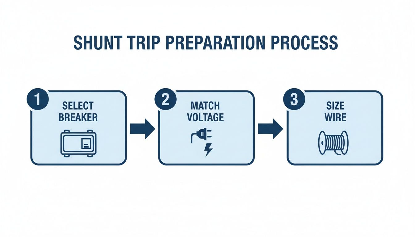
Nailing the Prep Work: Component Selection and Safety Checks
A rock-solid shunt trip installation is built on smart decisions made long before you even touch a wire. Getting the component selection and initial safety checks right from the get-go is everything. It's the difference between a smooth, reliable system and one plagued by costly rework and headaches down the road.
First things first, you need a circuit breaker that’s actually designed to have a shunt trip accessory installed. This isn't a "one-size-fits-all" situation. Always, and I mean always, check the manufacturer's datasheet to confirm compatibility. Trying to force a shunt trip onto a breaker that isn't built for it is a non-starter and a huge safety hazard.
Matching Coil Voltage to Your Control System
One of the most common—and frustrating—mistakes I see in the field is a mismatch between the shunt trip coil's voltage and the control power source. That little coil is just a solenoid, and if you feed it the wrong voltage, it’s either not going to work or you’ll burn it out.
The common options are usually 120V AC, 24V DC, or 24V AC.
Picture this: A beautiful new UL control panel is built around a slick 24V DC PLC system, but someone spec'd a breaker with a 120V AC shunt trip coil. Suddenly, you're scrambling for a last-minute control transformer and running extra wires, blowing up the budget and the timeline. Avoid the pain and confirm your control voltage before you order anything.
Sizing Your Control Wiring and Fuses
Once the voltage is sorted, you've got to size the control wiring and its overcurrent protection correctly. Shunt trip coils are inductive loads, which means they have an inrush current—a big gulp of amperage for a split second when it first energizes. This is a tiny detail that can cause major problems if you ignore it.
Dive back into that manufacturer datasheet and hunt for two key numbers:
Sealed/Holding Power: The steady power the coil needs (in VA or Watts).
Inrush Current/VA: The peak power it pulls to activate the trip.
Your control wiring (typically 14-24 AWG) has to handle that inrush spike without a major voltage drop. Even more critical is the fuse or mini-breaker protecting that circuit. It needs to be tough enough to let the inrush current pass without nuisance tripping, but sensitive enough to blow if there's a real overcurrent problem. A fast-acting fuse might pop every time you power up, while an oversized one offers zero protection.
A well-executed shunt-trip setup is a massive safety upgrade. Modern modules can trip a breaker in under 50–150 milliseconds of receiving a signal, allowing automated shutdowns that are lightyears faster than any human. In fact, studies show that up to 20–35% of control panel wiring issues found during commissioning trace back to mismatched control voltages or improperly fused trip circuits. It just shows how critical these upfront decisions really are. Find out more about how breakers work on Wikipedia.
For panel builders and integrators, this kind of meticulous planning is non-negotiable. Our complete guide on industrial control panel design dives even deeper into these principles. Getting these details right from the start is how you build a final UL-listed panel that’s both safe and absolutely dependable.
Taking the Shunt Trip Breaker Diagram from Paper to Panel
Alright, you've got the schematic figured out. Now comes the real test: translating that drawing into a clean, reliable circuit in the panel. This is where a little experience goes a long way. We'll walk through the wiring for two of the most common setups you'll see in the field—a classic Emergency Stop button and a more modern PLC-controlled trip.
The idea behind it is simple. You're just creating a switchable circuit that sends power to that little shunt trip coil. Once the initiating device—be it a button or a PLC relay—closes that circuit, voltage hits the coil, and boom, the breaker trips. Simple concept, but getting the details right is what makes it safe and dependable.
Before you even strip a wire, the prep work is key.
Nailing this sequence—matching the breaker, coil voltage, and wire gauge—is the first step to avoiding some of the most common headaches during installation.
Wiring the Classic Emergency Stop (E-Stop) Circuit
The E-Stop button is the bread and butter of shunt trip applications. It’s the big red button that gives anyone a way to kill power to a machine from a safe distance, a non-negotiable safety feature on pretty much any industrial equipment.
You only need a few parts for this job:
A solid control power source (a 120V AC control transformer is a common choice).
A fuse or small breaker to protect that control circuit.
The E-Stop button itself, which needs at least one normally open (N.O.) contact.
And of course, the shunt trip breaker.
The wiring couldn't be more straightforward. Your control power "hot" leg runs through the fuse, then heads to one side of the E-Stop's normally open contact. The other side of that contact wires directly to one of the shunt trip coil terminals (usually marked S1 or C1). To finish it off, the second coil terminal (S2 or C2) ties back to the neutral or common side of your control power.
When everything is normal, that N.O. contact is open, so the coil sees no voltage. The second someone hits that E-Stop, the contact slams shut, energizing the coil and tripping the breaker instantly.
Field Tip: Don't skimp here. Always use a proper, clearly labeled E-Stop button—the big, red, mushroom-head style. You want it to be unmistakable in a crisis. Using a normally open contact is also critical; it ensures the coil is only powered for a split second, preventing it from overheating and burning out.
Hooking Up a PLC-Controlled Shunt Trip
In automated factories, the signal to trip often comes from a Programmable Logic Controller (PLC). This lets the system automatically shut down equipment based on things like sensor faults, over-temperature alarms, or safety interlocks. The wiring is nearly identical to the E-Stop, but you're swapping the manual button for a PLC output relay.
The power flow is the same. Start with your fused control power, which feeds the "common" terminal on a PLC relay output. The normally open (N.O.) terminal from that same relay output then runs over to one of the shunt trip coil terminals. Just like before, the other coil terminal connects back to your control power neutral or common.
When the PLC's programming logic calls for a shutdown, it energizes that output relay. The contact closes, sends the juice to the shunt trip coil, and the main breaker opens. This is a go-to setup for everything from tripping a large motor during a fault to shutting down a conveyor line when a safety gate is opened.
Critical Wiring and Grounding Habits
No matter what's triggering the trip, a few practices are non-negotiable. These are the small details that mark the difference between a pro install and a future service call.
Label Every Wire: Seriously. Label every control wire at both ends, saying where it came from and where it's going. It turns a future troubleshooting nightmare into a simple, logical process.
Watch DC Polarity: If you're working with a DC coil (like 24V DC), mind the polarity. The terminals will almost always be marked with a (+) and (-). Reversing them can easily fry the coil.
Ground Everything: The breaker's metal enclosure and any other metallic parts need a solid connection to the equipment ground. This is basic electrical safety 101 to prevent shock if there's ever a fault.
Torque It Down: Use a torque screwdriver and tighten every terminal to the manufacturer's spec. A loose control wire is a recipe for an intermittent problem, which is one of the toughest things to track down in the field.
Wiring a shunt trip breaker is about more than just connecting the dots. You're building a safety circuit that has to work, without fail, when it matters most. By following these practical steps and field-tested tips, you can be confident your installation will be right, and more importantly, reliable.
Testing and Maintaining Your Shunt Trip System
Getting the wiring diagram for a shunt trip circuit breaker right is a great start, but it's just that—a start. Real-world reliability comes from putting the system through its paces with rigorous testing and then sticking to a consistent maintenance schedule.
This is the commissioning phase, where you prove the system will snap into action the second it's needed in an emergency. Without this final check, you're not engineering a safety system; you're just hoping it works.
The goal is simple: make sure that hitting your remote E-stop or triggering a signal instantly opens the circuit breaker. This isn't just a "nice to have." It’s a critical safety function that demands documented proof it works before you ever turn the system over for live operation.
Commissioning Your Shunt Trip Circuit
Before you flip any switches, a few last-minute visual checks are in order. Grab your torque wrench and make sure every terminal screw is tightened to the manufacturer's spec. A loose control wire is one of the most common reasons a brand-new installation fails its first test. Double-check that your wire labels match the diagram and that the control circuit fuse is the right size and properly seated.
Once everything looks good, the test itself is straightforward, but you have to be methodical.
Check Your Control Voltage: First things first, keep the main breaker OFF and energize only the control circuit. Get your multimeter out and verify you have the correct voltage—whether it's 120V AC or 24V DC—at the line side of your E-stop button or other initiating device. This quick check tells you the control power source is healthy and ready to go.
Test the Trip: With the area clear and all safety protocols followed, turn the main circuit breaker ON. Now, hit the initiating device. Press the E-stop or trigger the PLC output. You should hear a solid, satisfying "clack" as the breaker trips open.
Confirm De-energization: After the breaker trips, use your multimeter again to confirm zero voltage on the load side of the breaker. This is the crucial step that proves the main contacts have fully opened and the downstream equipment is truly isolated.
Reset and Repeat: Finally, reset the E-stop button or clear the PLC signal, and then reset the circuit breaker itself. It should reset cleanly without tripping again. If it re-trips immediately, you might be dealing with a stuck contact in your E-stop or a latched PLC output that needs a closer look.
The Importance of Long-Term Maintenance
A shunt trip system isn't something you can just "set and forget." Over time, plant vibrations can loosen terminals, dust and grime can gum up mechanical parts, and coils can eventually fail. The only way to ensure it works five years from now is to implement a regular, documented maintenance plan.
Industry data on circuit breaker failures tells a powerful story. Analyses from 1980–2000 found that failures in mechanical and auxiliary trip assemblies (including shunt trips) were behind roughly 24-26% of common-cause failures. The primary culprit? Inadequate maintenance. The data also shows that routine functional testing can reduce the odds of a trip failure during an emergency by an estimated 30–60%. You can get the full story from this in-depth reliability study.
For any plant engineer or maintenance manager, that data is a clear call to action. A preventive maintenance schedule isn't optional; it's essential.
A Practical Maintenance Checklist
A simple checklist helps keep your technicians consistent and ensures nothing gets missed. For most industrial environments, running through these checks every 6 to 12 months is a solid best practice.
Visual Inspection: Look for the classic signs of overheating, like discolored plastic on terminals or browned wire insulation. Check for any buildup of dust or debris around the breaker and its mechanism that could interfere with its operation.
Terminal Tightness: With the system fully de-energized and locked out, put a torque wrench on every control and power terminal. Loose connections are a top cause of intermittent problems and outright failures.
Functional Test: This is the big one. Run the exact same commissioning test you did on day one. Activate the trip device and confirm the breaker opens instantly. It’s the only way to know for sure that the coil and mechanism are still in good working order.
Documentation: Log everything. Write down the date, the technician’s name, and the pass/fail result of the functional test. This logbook is gold during a safety audit and is critical for tracking the health of your safety systems over their entire lifecycle.
This disciplined approach to testing and maintenance is what turns a well-wired diagram into a dependable safety system you can truly count on.
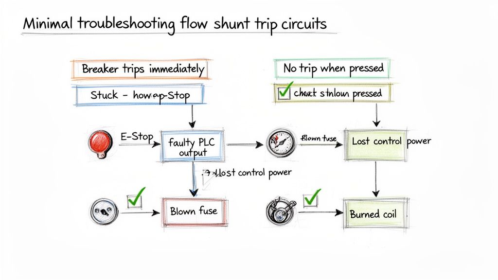
Troubleshooting Common Shunt Trip Wiring Problems
Even when you’ve followed a wiring diagram to the letter, things go sideways in the field. When a brand-new safety circuit fails its first test, the pressure is on to find the glitch—and fast.
Let's walk through the most common headaches I've seen and how to diagnose the root cause with a bit of logic. A systematic approach is your best friend here. Instead of just poking around, we’ll tackle these issues based on what you’re seeing, which isolates the variables and gets you to the solution much more quickly.
Symptom One: The Breaker Trips Immediately on Reset
This is a classic. You go to close the breaker handle, and click—it immediately snaps back open. This almost always points to an active trip signal. The shunt coil is getting power the instant you try to reset the breaker.
The cause is rarely the breaker itself. More often than not, the initiating device is stuck in the "closed" or "tripped" position, continuously sending voltage right to the coil.
Here’s where to start your investigation:
Check the E-Stop Button: Is a mushroom-head E-stop actually pulled out to its reset position? I can't count how many times I've seen a button still latched in from a previous test or bump.
Inspect PLC Outputs: If a PLC is running the show, you need to look at the logic and the status of the output relay. A sticky relay or a simple programming error could be holding that contact closed.
Look for Shorted Wires: It’s less common, but the control wires going to the shunt coil could be shorted together somewhere. This effectively bypasses the initiating device and sends constant power straight to the coil.
Troubleshooting Takeaway: An immediate re-trip means your control circuit is "live." The problem isn't the breaker failing; it's the trip signal never turning off. Focus your energy on whatever is sending that signal.
Symptom Two: The Trip Button Does Nothing
The complete opposite problem is just as common: you slam the E-stop button, and… nothing. The breaker stays closed, and the equipment keeps humming along. This tells you there's a break somewhere in your control circuit, preventing voltage from ever reaching that shunt coil.
When you hit this wall, think of it as tracing a path of electricity and finding where it dead-ends.
A Logical Diagnostic Path:
Verify Control Power: Is the control circuit even on? Grab your multimeter and confirm you have the proper voltage (e.g., 120V AC or 24V DC) at the source. It’s a dead-simple first step that often ends the search right there.
Check the Control Fuse: This is the number one culprit, hands down. A blown fuse in the control circuit will kill power to the entire trip system. Always keep spares in your bag.
Test the Initiating Device: With the power off, switch your meter to continuity and test the E-stop or relay contact. Does it show a closed circuit when you press the button? Contacts wear out and fail. It happens.
Inspect the Shunt Coil: If you confirm power is reaching the coil terminals when the button is pressed but the breaker isn't tripping, the coil itself is likely toast. You can test its resistance (with power off, of course) and check it against the manufacturer’s spec sheet.
Common Questions About Wiring a Shunt Trip Breaker
Even with a perfect diagram, wiring up a shunt trip breaker for the first time can bring up a few questions. Let's walk through some of the most common sticking points I see in the field to make sure your installation is safe and works the first time.
Can a Shunt Trip Coil Stay Energized?
Absolutely not. If you remember only one thing, make it this: a shunt trip coil is built for momentary duty only. Think of it like the starter in your car—it just needs a quick jolt of voltage to do its job.
Leaving constant power on the coil is a surefire way to burn it out, and it happens fast. We're talking a matter of minutes. That's why your control device, whether it's an E-stop button or a relay, must use a normally open (N.O.) contact that only closes for the brief moment you need to trip the breaker.
What Happens If I Use the Wrong Voltage on the Coil?
Using the wrong voltage is a recipe for failure, simple as that. The results are predictable, and neither is good.
Under-voltage: If you send 24V DC to a 120V AC coil, for example, you won't get enough magnetic force to trip the breaker. The coil just won't have the muscle to work the internal mechanism. Your safety circuit will be completely useless.
Over-voltage: This is even more dramatic. Hooking up 120V AC to a 24V DC coil will cause it to instantly overheat and fry itself. You'll get a puff of smoke, a dead coil, and maybe even a damaged breaker.
Before you land a single wire, double-check the voltage rating printed right on the shunt trip accessory against your control circuit's power source. It's a five-second check that prevents a costly headache.
Is a Separate Fuse for the Shunt Trip Circuit Necessary?
Yes, and it's not optional. The control circuit for the shunt trip needs its own dedicated overcurrent protection, usually a small fuse or a miniature circuit breaker. This little fuse is there to protect the control wiring and the coil itself if a short circuit ever happens.
Without that fuse, a fault in your control wiring could become a fire hazard or take down your entire control power supply. Sizing is crucial here. You need a fuse rated to handle the coil's quick inrush of current without popping, but small enough to blow instantly on a real fault. Check the manufacturer's spec sheet, but you're typically looking for something between 0.5A and 2A.
Can I Add a Shunt Trip to Any Circuit Breaker?
Nope. Shunt trip accessories aren't a universal, one-size-fits-all part. The circuit breaker itself has to be designed from the factory to accept a shunt trip module. These specific breakers have the necessary internal linkages and mounting slots for the accessory to physically connect and operate.
Trying to force a shunt trip into a standard breaker that wasn't made for it is just not going to work and is completely unsafe. Always confirm your breaker's model number can take a shunt trip by checking its technical documents before you buy anything.
Thankfully, finding compatible components is getting easier. The global market for these accessories was around USD 1.1 billion in 2024 and is expected to double by 2033, thanks to a huge push for better industrial safety and automation. This growth means better availability and clearer documentation from manufacturers. You can dig into this market trend over on Verified Market Reports.
What Is the Difference Between a Shunt Trip and an Undervoltage Release?
I hear this one all the time. It's easy to get them mixed up, but they do the exact opposite job.
Shunt Trip (ST): This trips the breaker when you apply voltage to it. Think of it as an active, "trip on command" device. It's what you need for E-stops and remote shutdowns.
Undervoltage Release (UVR): This trips the breaker when voltage is lost or dips too low. It needs constant power to hold the breaker closed. This is used to prevent equipment from unexpectedly restarting after a power failure.
Choosing the right one is all about the safety function you're trying to achieve. If it's an emergency stop, you always want a shunt trip.
At E & I Sales, we specialize in providing correctly specified UL-listed control solutions, including pre-wired and tested shunt trip circuits that eliminate guesswork and ensure your systems meet the highest safety standards. For expert guidance on your next project, visit us at https://eandisales.com.
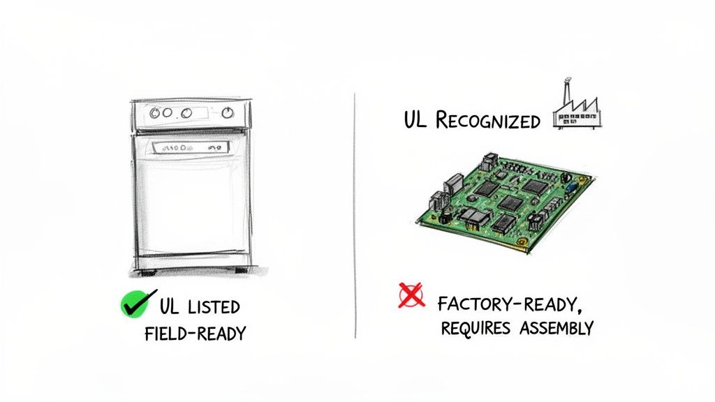
The most crucial thing to grasp when talking about UL Listed vs UL Recognized is where the product is headed. Is it a finished product ready for an electrician to install in the field, or is it a component destined for a factory assembly line?
That's the fundamental split: UL Listed applies to standalone products, while UL Recognized is for components that get installed inside a larger piece of equipment. One is the final product; the other is a part of the whole.
Understanding The Core Difference
Let’s break it down with a simple analogy. Think of a UL Listed control panel as a brand-new car you buy from a dealership. It's fully assembled, it's been crash-tested, and it's ready to be driven off the lot. The entire vehicle has been evaluated as a single, functional unit for safety and performance.
A UL Recognized component, on the other hand, is like a high-performance engine. That engine has been individually tested and proven to meet certain standards under specific conditions. But you can't just put the engine on the road. It needs to be correctly installed in a car (the final assembly) by professionals in a factory, where its interaction with the brakes, chassis, and electronics will be evaluated.
This dual-track system was a smart move by UL. It allows manufacturers to source pre-certified components without having to re-test every single switch and power supply from scratch. This makes the path to getting a complex machine—like a packaging line or a control panel—UL Listed much more efficient. You can find more historical context on this system at triadmagnetics.com.
Key Differences UL Listed vs UL Recognized at a Glance
When you're designing a machine or specifying parts, knowing the difference isn't just academic—it has real-world consequences for cost, compliance, and field acceptance. This table boils down the essential distinctions you need to know.
Attribute
UL Listed
UL Recognized
Product Type
Standalone, complete end-products (e.g., control panels, motors, appliances).
Components or parts for factory installation (e.g., relays, power supplies, circuit boards).
Application Scope
Meant for field installation and direct use by end-users.
Intended for use within a larger UL Listed assembly or system.
Evaluation Focus
Comprehensive safety and performance testing of the entire product.
Focused testing of a component under specific, limited conditions.
Marking
Circular "UL" mark, often with the word "LISTED."
Backward "UR" or "RU" mark, signifying a Recognized Component.
Field Acceptance
Accepted by Authorities Having Jurisdiction (AHJs) and inspectors.
Not accepted as a standalone product in the field; requires evaluation in the final assembly.
Ultimately, choosing between specifying Listed or Recognized components comes down to your final goal. Are you building a system from the ground up, or are you installing a finished piece of equipment? The answer will guide you to the correct UL mark every time.
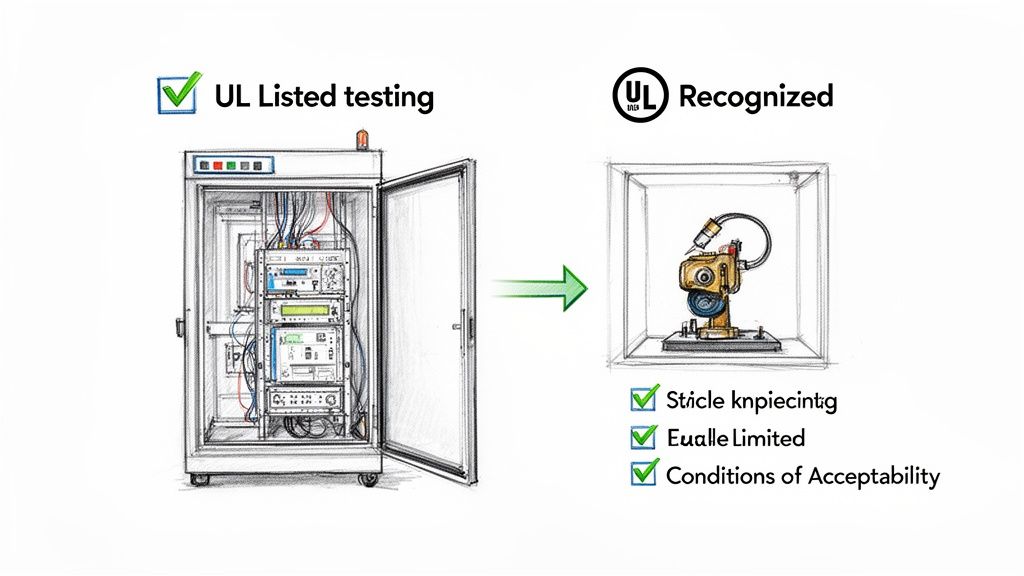
Inside The UL Certification and Testing Process
The line between UL Listed and UL Recognized isn't just a label on a product; it’s the result of two completely different testing philosophies. If you’re an engineer or designer, getting this right is critical, as it determines exactly how a product or component can be integrated into a system safely and by the book. The journey to each mark evaluates different things, leading to very different outcomes.
A UL Listed product gets the full, top-to-bottom evaluation. UL’s engineers test the complete, standalone unit exactly as it would be installed and used in the field. The whole point is to ensure the product is free from any reasonably foreseeable risk of fire, electric shock, or other hazards you might encounter in its final environment.
The process for a UL Recognized component, on the other hand, is much more surgical. It certifies a part, not a finished product. The tests are tailored specifically to that component's job inside a bigger piece of equipment, and its certification is only valid when used under a very precise set of rules.
The Scope of UL Listed Testing
When a product like an industrial control panel goes in for a UL Listing, it's put through a gauntlet of tests that check its overall safety and durability as a complete system. This goes way beyond just making sure the internal wiring is correct; it's a comprehensive audit of the entire assembly.
Key testing areas for UL Listed products include:
Construction Integrity: UL experts examine the physical enclosure for sturdiness, corrosion resistance, and its ability to shield live parts from accidental contact.
Electrical Safety: This is a deep dive into proper grounding, insulation, and the securement of live parts. They also verify that all electrical clearances meet strict standards.
Performance Under Stress: The product gets hit with normal and fault conditions—think power surges or short circuits—to ensure it fails safely without starting a fire or creating a shock hazard.
Environmental Durability: Depending on where the product is meant to be used, it might face tests for resistance to dust, water ingress (like a high-pressure hosedown), and even ice formation.
The entire philosophy behind a UL Listing is to validate a product's safety as a whole, right in its final, intended application. It answers one simple question: "Is this entire device safe for an electrician to install and for an operator to use in the real world?"
This exhaustive approach is exactly why getting a UL Listing is a more rigorous, time-consuming, and expensive journey. It certifies the product for field installation, giving Authorities Having Jurisdiction (AHJs) the green light they need to approve its use on-site.
The Nuances of UL Recognized Evaluation
In sharp contrast, the evaluation for a UL Recognized component is highly specific and deliberately limited. Think of a power supply or a circuit board that’s designed to live inside a larger machine. UL doesn’t test it as a standalone item because it was never meant to be one.
Instead, the testing hones in on its performance within a controlled, factory setting. The make-or-break detail here is the Conditions of Acceptability. These are critical limitations and requirements that UL attaches to the component's certification file.
These conditions might specify things like:
Maximum voltage and current ratings.
Specific enclosure requirements needed for fire or shock protection.
A required mounting orientation.
The maximum ambient operating temperature.
A UL Recognized component is only considered certified if the end-product manufacturer follows all of its Conditions of Acceptability to the letter. If an engineer uses a UL Recognized relay but puts it in an enclosure that doesn’t meet the conditions specified in its file, the relay's certification is instantly void for that assembly.
This is the fundamental trade-off. UL Recognition offers a more streamlined and less expensive path for component manufacturers. It lets OEMs build with pre-vetted parts, which simplifies their own final UL Listing process. But—and this is a big but—it puts all the responsibility on the OEM to understand and follow every single one of the component’s limitations. This is why a Recognized mark signals factory-readiness, while a Listed mark confirms field-readiness.
Meeting Regulatory Requirements and Gaining Market Access
Deciding between a UL Listed product and a UL Recognized component is far more than just a technical choice—it's a critical business decision that determines whether you can sell your product, pass inspections, and operate legally. This distinction is the key that unlocks market access, especially in North America where inspectors and regulators hold the final say over what gets installed.
Getting this wrong can lead to crippling delays, rejected projects, and serious legal exposure.
At the heart of the matter is UL's official standing. In the United States, UL is a Nationally Recognized Testing Laboratory (NRTL), a designation granted by the Occupational Safety and Health Administration (OSHA). This isn't just a fancy title; it gives the UL mark real teeth in the eyes of regulators.
The Role of Authorities Having Jurisdiction
On any job site, the ultimate gatekeeper is the Authority Having Jurisdiction (AHJ). This could be a city electrical inspector, a fire marshal, or another code official. Their job is simple: make sure every piece of equipment meets established safety codes, like the National Electrical Code (NEC).
The NEC and local codes are very clear—they often require electrical equipment to be "listed" or "labeled" by a qualified lab. For an AHJ, seeing a UL Listed mark on a product is a green light. It’s a trusted, unambiguous sign that the equipment has been fully tested and is safe to install right out of the box.
A UL Recognized mark tells a completely different story to an inspector. They see it and immediately know the component's safety is conditional. Because it hasn't been evaluated as a complete, standalone system, they will fail it on sight.
That's the difference between a smooth project sign-off and a stop-work order that brings everything to a grinding halt.
Gaining Access to Commercial Markets
The power of the UL Listed mark goes way beyond the job site. It's a non-negotiable commercial requirement. Major distributors, retailers, and industrial suppliers have procurement policies that flat-out demand UL Listing for the products they sell.
It all comes down to liability and risk management. Big players in the market know that UL markings carry different legal and practical weight. They won't touch a product that could put them or their customers at risk. Trying to sell an end-product built with only UL Recognized components is a recipe for commercial failure.
You'll run into some serious business hurdles:
Limited Sales Channels: Forget about getting stocked by major distributors. Most will refuse to carry a non-Listed product.
Customer Rejection: Savvy industrial buyers know what to look for. They won't purchase equipment that they know will fail an inspection.
Insurance and Liability Issues: If an incident like a fire occurs, you can bet the insurance company will scrutinize every component. Using unlisted parts or misapplying Recognized components can lead to denied claims and devastating legal liability.
Navigating the Risks in Control Panel Design
Nowhere are these risks more apparent than in the world of industrial control panels. A control panel is an assembly of countless individual parts, but the finished product must be evaluated as a single, cohesive system to earn a UL Listing under a standard like UL 508A.
You can't just throw a bunch of UL Recognized components into a box and call it a day. That doesn't automatically make the panel compliant.
The panel builder is on the hook for making sure every component is used exactly as its "Conditions of Acceptability" dictate and that the entire design meets the tough construction requirements of UL 508A. For a deeper dive, our guide on industrial control panel design breaks down these critical steps.
Ultimately, the UL Listed mark is your passport to market entry and regulatory approval. It is the definitive proof that a product is complete, safe, and ready for the real world. Relying only on the Recognized status of its internal parts leaves a dangerous—and expensive—compliance gap that can put your whole operation at risk. And remember, product certifications are just one piece of the puzzle; a full understanding of workplace safety protocols, like the NFPA 70E electrical safety standards, is essential for true compliance.
Making The Right Choice in Procurement and Specification
Getting the sourcing decision wrong between UL Listed and UL Recognized isn't just a small technical slip-up. It's the kind of mistake that blows up project timelines and budgets. For any procurement manager or specifying engineer, knowing when to demand each certification is critical for getting a project from design to final sign-off without a hitch.
The whole decision really boils down to one simple question: where will this item be installed?
If it's going directly into the field as a standalone piece of equipment, the path is clear—it absolutely must be UL Listed. But if it's just one component being tucked inside a larger assembly in a controlled factory setting, then a UL Recognized part is usually the right—and more cost-effective—call.
Crafting a Compliant Procurement Specification
A vague spec is just asking for trouble. To sidestep any confusion and ensure you get the right parts, your procurement documents have to be crystal clear. Think of a solid specification checklist as your first line of defense against supply chain headaches and non-conforming parts.
Here’s what every single spec sheet should require:
Define the Certification Type: Be explicit. State "UL Listed" for standalone gear or "UL Recognized" for internal components. Vague terms like "UL Certified" or "UL Approved" are technically meaningless and should never be used.
Request UL File Numbers: Always require suppliers to provide the specific UL file number for every certified product. That number is your golden ticket to verifying the certification's authenticity and scope.
Specify the Relevant UL Standard: For something like an industrial control panel, you need to call out the specific standard, like UL 508A. This makes sure the final product is built to the exact safety and construction rules for its job.
When you specify a UL Recognized component, never forget that its certification comes with strings attached. Your design and assembly teams are on the hook for understanding and following its 'Conditions of Acceptability.' If you don't, you've just voided that component's UL status within your final product.
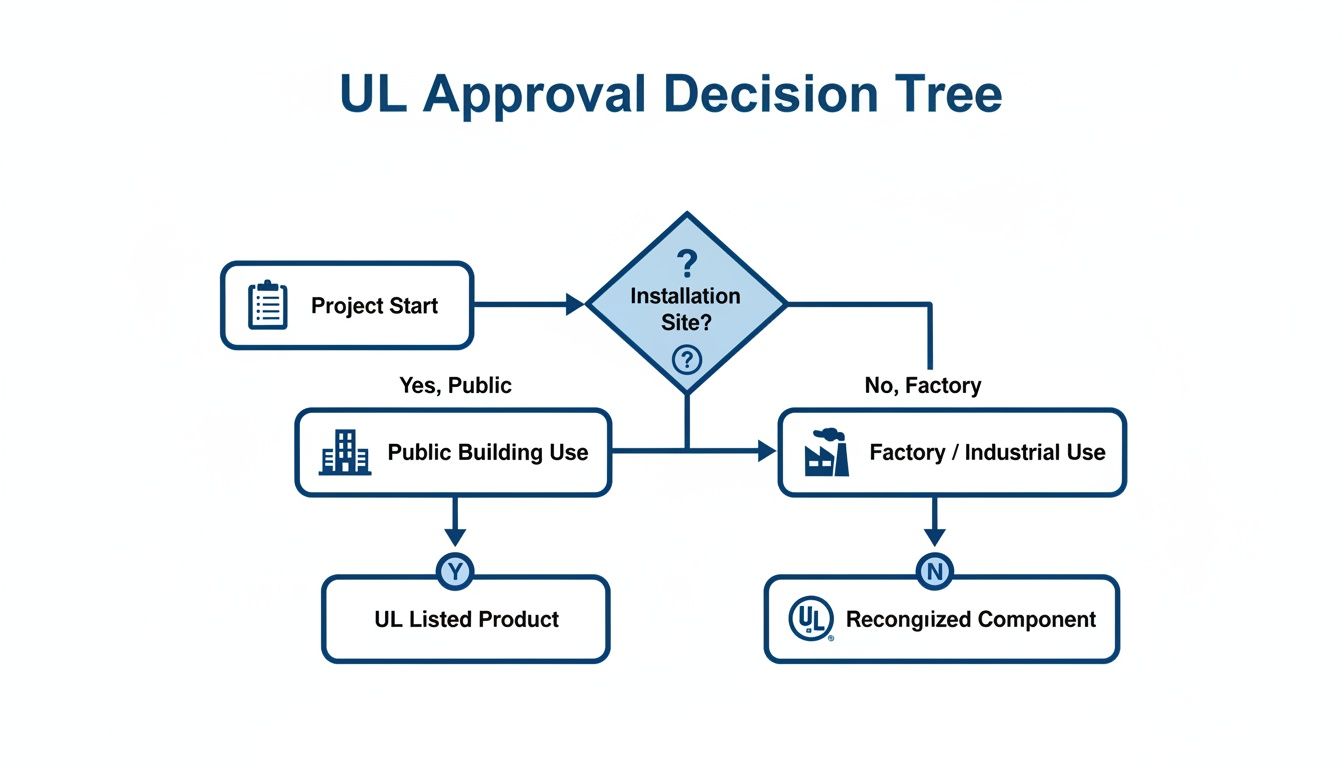
This decision tree gives a nice visual of how the final installation site dictates the procurement path.
As the flowchart shows, any equipment heading out for public or field installation needs a full UL Listing. Components intended for factory integration, on the other hand, can be UL Recognized.
Interpreting Conditions of Acceptability
Sourcing UL Recognized parts doesn't stop once you have the UL file number. The next step is the most important one: digging into the "Conditions of Acceptability." These are the specific rules and limitations UL has defined for that component to ensure it operates safely within a larger system.
These conditions will often spell out details like:
Electrical Ratings: Maximum voltage, current, and short-circuit current ratings (SCCR).
Environmental Constraints: Min/max operating temps or required enclosure types.
Mounting and Spacing: Specific orientations or minimum clearances needed from other components.
Ignoring these conditions is a surefire way to fail the final UL Listing evaluation for your finished assembly. It completely undermines the reason for using a Recognized component to begin with, leading to expensive rework and painful delays. This is a massive point for any control panel builder trying to get a UL 508A Listing on their panel.
Paying close attention to these details ensures every part works for your final system's compliance, not against it. This kind of disciplined approach turns the tricky ul listed vs ul recognized choice into a clear, repeatable process for success.
How To Verify UL Marks and Avoid Counterfeits
Just spotting a UL mark on a product isn't enough to guarantee it’s legitimate. The reality is that counterfeit marks are a persistent headache in the supply chain, creating massive safety risks and liability for everyone involved, from the OEM right down to the plant engineer. A quick visual check is where you start, but real due diligence is digital.
The physical marks themselves offer the first clues. A UL Listed product will almost always have that iconic "UL" inside a circle. On the other hand, a UL Recognized component uses a backward "UR" or "RU" symbol, which is an immediate sign that it's meant for factory installation and isn't a standalone device.
But here’s the problem: counterfeiters have gotten very good at faking these logos. Relying on a label alone is a gamble, especially when you're dealing with something as critical as a miniature circuit breaker, where a failure can have catastrophic results. You have to dig deeper.
The Role of the UL File Number
Every single genuine UL certified product or component has a unique UL File Number. This alphanumeric code is the key to everything—it unlocks the product's entire certification history and scope of use. You'll typically find it printed right on the product label, usually somewhere near the UL mark itself.
Think of this file number as more than just an ID; it's your direct line into UL's official records. Without it, you can't truly verify a thing. If a supplier ever hesitates or can't provide the UL file number for a product they claim is certified, that's a major red flag.
Using the UL Product iQ Database
The definitive tool for verification is the UL Product iQ™ database. This is UL's official online directory of every certified product and component, and it's free for anyone to use. It lets you look up a file number and confirm a product's status in real-time.
The process is straightforward and should be a non-negotiable step for any procurement or quality control team.
Find the UL File Number: Locate the number on the product's label, its packaging, or in the technical datasheet. For many electrical components, it often starts with the letter "E".
Go to UL Product iQ: Navigate to the official UL Product iQ website. You'll need to create a free account to get access.
Enter the File Number: Punch the complete file number into the search field.
Review the Details: The results will show you the manufacturer's name, the exact UL standard the product was tested against, and—critically—any "Conditions of Acceptability" for UL Recognized components.
If your search for a file number comes up empty, or if the details in the database don't match the product you have in your hands, the UL mark is almost certainly counterfeit or being misused. At that point, reject the product immediately and consider reporting the issue to UL's anti-counterfeiting team.
This simple, data-driven process is the single most powerful tool you have to protect your projects, equipment, and people from the risks of non-compliant parts. It takes the guesswork out of it.
Frequently Asked Questions About UL Certifications
When you're in the trenches designing a system or specifying parts, the distinction between UL Listed and UL Recognized can get a little fuzzy. Let's clear up some of the most common questions that pop up for engineers, procurement managers, and plant operators. Getting these details right is what keeps a project on track and ensures everything is safe and compliant.
Can I Use a UL Recognized Component as a Standalone Product?
Let's make this crystal clear: Absolutely not. A UL Recognized component is, by definition, incomplete. Think of it as a pre-approved ingredient, not the finished meal. Its certification is entirely conditional, meaning it's only valid when used inside a larger system that will eventually get its own full UL Listing.
These parts have only been vetted for a very specific job and haven't gone through the rigorous testing required for a complete device that an electrician would install in the field. An Authority Having Jurisdiction (AHJ)—like your local electrical inspector—would red-flag a field-installed Recognized component in a heartbeat. It simply doesn't meet the electrical code requirements for finished equipment, creating a serious safety hazard and a massive liability risk.
What Are the "Conditions of Acceptability" for a UL Recognized Part?
When UL gives a component its "Recognized" stamp, they issue a report that includes its "Conditions of Acceptability." These aren't suggestions; they are the hard-and-fast rules you must follow when designing that component into your product.
This rulebook is incredibly specific and can cover a wide range of critical parameters.
Electrical Ratings: This will define the absolute maximum voltage, current, or Short Circuit Current Rating (SCCR) the part can safely handle.
Thermal Limits: It might specify a maximum ambient operating temperature or mandate the use of a specific heat sink to keep it cool.
Enclosure Requirements: It will often require a particular type of enclosure to provide the necessary protection against fire or electric shock.
Mechanical Constraints: You might find details on a required mounting orientation or the minimum spacing needed between it and other components.
The final UL Listing evaluation for your end product will absolutely involve an engineer verifying that you've followed all the Conditions of Acceptability for every single Recognized component you used. If you miss even one, that component's Recognition is void, and your entire product will likely fail its own Listing evaluation. That means expensive redesigns and painful project delays.
Is It Better to Build a Control Panel With All UL Listed Components?
Not really, and honestly, it would usually be impractical and far too expensive. While it's standard practice to use certain UL Listed components like main circuit breakers or power supplies, the real goal is to get a UL Listed final assembly—like a control panel built to the UL 508A standard.
The UL 508A standard was written specifically to guide panel builders on how to correctly and safely use both Listed and Recognized components. Using UL Recognized terminal blocks, relays, contactors, and pilot lights is often much more cost-effective and gives designers the flexibility to create more compact and efficient layouts.
The key takeaway here is that the panel builder must follow the UL 508A standard to the letter and respect every component's unique "Conditions of Acceptability." The focus isn't on the status of every single part inside the box, but on the compliance and Listing of the final, complete panel.
How Do Costs and Timelines Compare for Listed vs. Recognized?
As a general rule, getting a component UL Recognized is significantly cheaper and faster than getting a full product UL Listed. The difference really boils down to the scope of the evaluation.
A Recognition investigation is narrow and focused, looking only at the component itself under a very specific, pre-defined set of conditions. In contrast, a full Listing is a holistic and exhaustive evaluation of the entire end product. That process scrutinizes the enclosure, user interface, overall construction, and performance under all sorts of real-world scenarios, including fault conditions.
This massive difference in testing scope means a full Listing involves more engineering hours, higher lab fees, and a much longer back-and-forth with UL. Based on industry experience, the Recognition process can be 30% to 70% cheaper and might only take a few weeks. A full Listing for a complex piece of equipment, however, can easily take several months from start to finish. This cost-benefit trade-off is exactly why the UL Recognized path exists—it lets component makers provide pre-vetted parts that help OEMs streamline and speed up the Listing process for their own final products.
At E & I Sales, we specialize in navigating these complexities every day. Whether you need expertly engineered UL-listed control panels or premium electric motors for your next project, our team provides the deep product expertise and integration support to ensure your solutions are reliable, code-compliant, and delivered on schedule. Learn how we can help you accelerate your projects and reduce downtime.
Sizing a motor starter isn't just about matching a few numbers on a spec sheet. It’s about creating a perfect partnership between your motor and its protective device, ensuring everything runs smoothly, safely, and without costly interruptions. You're selecting a contactor and overload relay that can handle the raw power of motor startup and the long haul of daily operation, all while standing guard against electrical faults.
Get this right, and you’ve built in protection and reliability. Get it wrong, and you’re looking at fried equipment and unscheduled downtime.
Why You Can't Afford to Guess on Starter Sizing
Before we jump into the nitty-gritty of charts and calculations, let's talk about why this is one of the most critical tasks for any plant engineer or control packager. A motor starter is more than a simple on/off switch; it’s the motor's bodyguard.
Think of it as a two-part system. First, you have the contactor, the heavy-lifter that makes and breaks the high-current circuit needed to get the motor spinning. Then you have the overload relay, the vigilant watchdog that monitors the current. If the motor starts drawing too much power for too long, the overload relay steps in and trips the circuit, saving the motor from a slow, expensive death by overheating.
The Bedrock of a Safe, Compliant System
Every choice you make here is guided by standards, with the National Electrical Code (NEC) being the law of the land. Specifically, NEC Article 430 lays out the rules of the road for everything from conductor sizes to overload protection. Following these rules isn’t just good practice—it’s mandatory for creating safe installations that protect your people and your machinery.
This process chart shows the foundational thinking that needs to happen before you even touch a calculator.
It’s a simple but powerful reminder: start with accurate data and a clear understanding of the standards you need to meet.
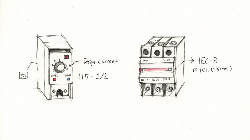
The Big Decision: NEMA vs. IEC
Early on, you'll face a fork in the road. Will you go with NEMA or IEC standards? They both get the job done, but they have very different philosophies.
NEMA (National Electrical Manufacturers Association) starters are the classic North American workhorses. They're built tough, sized conservatively based on standard horsepower ranges, and can take a beating.
IEC (International Electrotechnical Commission) starters are the more modern, "Euro-style" choice. They’re compact, often more cost-effective, and demand a precise sizing approach based on the motor's exact current draw and application details.
This choice dictates everything from how much space you need in the panel to how deep you need to go with your calculations. It’s no surprise that the demand for these components is surging. The global motor starter market jumped from USD 7.4 billion to USD 7.8 billion in just one year and is on track to hit over USD 12 billion by 2034. That growth is a testament to how critical proper motor control is in today’s industrial world.
Key Takeaway: Sizing a motor starter is a strategic engineering decision, not just a technical task. It directly impacts your facility's uptime, the lifespan of your equipment, and overall safety. A miscalculation can easily lead to nuisance trips, motor failure, and a major hit to your bottom line.
Quick Sizing Checklist Overview
To keep things straight, here’s a high-level look at the steps we'll be walking through. This table outlines the critical actions you'll take at each stage of the sizing process, ensuring nothing gets missed.
Sizing Step
Key Action
Governing Standard
Gather Motor Data
Record motor nameplate HP, voltage, FLA, and Service Factor.
NEC Tables / Manufacturer Data
Determine FLA
Use nameplate FLA if available; otherwise, use NEC tables.
NEC Article 430
Apply Derating Factors
Adjust for high ambient temperatures and altitudes.
NEMA / IEC Standards
Select Overload Relay
Set the trip current based on motor FLA and Service Factor.
NEC 430.32
Choose Contactor/Starter
Select a starter rating that meets or exceeds the motor HP.
NEMA ICS 2 / IEC 60947
Verify Coordination
Ensure proper short-circuit protection and coordination.
UL 60947-4-1 / NEC 430.52
Following this structured approach turns a potentially complex task into a manageable and repeatable process, giving you confidence in your final selection.
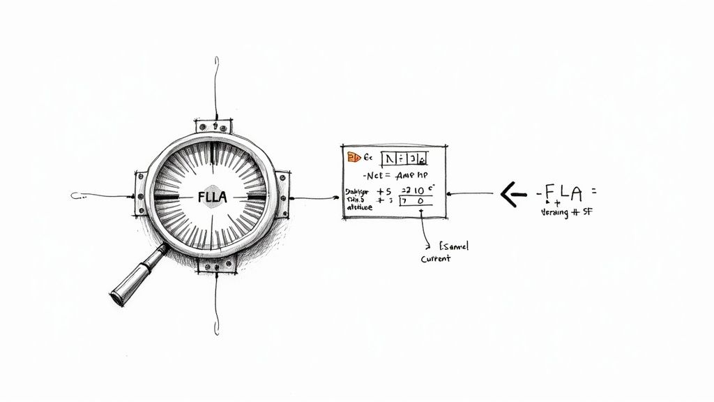
Before you can even think about picking out hardware, you need to nail down one absolutely critical number: the motor’s Full-Load Amps (FLA).
Everything that follows—the overload relay, the contactor, the short-circuit protection—is based on this value. It’s the current the motor is designed to pull when it’s running at its rated horsepower, and getting it wrong is a recipe for disaster.
Start with the Nameplate FLA
The first place you should always look for the FLA is right on the motor's nameplate. This is the manufacturer's certified data, your ground truth for that specific piece of equipment. You'll usually find it listed right alongside the horsepower (HP), voltage, and phase.
But we’ve all been there. You get out to the floor, and the nameplate is covered in 20 years of paint, corroded beyond recognition, or just gone. Now what?
This is when you turn to the industry’s trusted backup plan: the National Electrical Code tables. For a three-phase motor, you'll want to pull up NEC Table 430.250. This table gives you a standardized FLA based on horsepower and voltage. It's important to know that these values are intentionally a bit conservative—often higher than the actual nameplate FLA—to account for swings in motor efficiency and power factor. That built-in safety margin makes them a solid, reliable substitute when you can't read the nameplate.
A Critical Distinction: NEC 430.6(A) lays out a rule that trips people up all the time. You must use the NEC table values for sizing your wires (conductors) and your short-circuit protection (fuses or breakers). But for setting the overload relay, you must use the actual nameplate FLA. This little detail is key to preventing nuisance trips while still making sure your wiring can handle the load.
Adjusting for Real-World Conditions
A motor's nameplate rating assumes it’s operating in a perfect lab—usually at sea level and a comfortable 40°C (104°F). Your plant is probably not a perfect lab. That's where derating factors come in.
Two big environmental factors can make a motor work harder and pull more current than expected:
High Ambient Temperature: If a motor is running in a space hotter than its 40°C design rating, it can't cool itself effectively. To keep from burning up, its effective horsepower has to be reduced, or "derated."
High Altitude: Ever try to catch your breath at high elevations? Motors feel it, too. At altitudes above 3,300 feet (1,000 meters), the air is thinner and less effective at cooling. This also forces a derating.
These factors stack. A motor in a hot facility located high in the mountains is going to need a significant adjustment.
Don't Forget the Service Factor
The last piece of the puzzle is the Service Factor (SF), another value you'll find on the nameplate. Think of the Service Factor as a built-in "overload" capacity that the motor can handle for short bursts without damage.
A standard motor typically has an SF of 1.15.
Many newer energy-efficient motors have an SF of 1.0.
An SF of 1.15 means the motor can safely handle a load 15% greater than its rated horsepower. This is hugely important when setting your starter's overload protection. Per NEC 430.32, you can set the overload trip point up to 125% of the nameplate FLA if the motor has an SF of 1.15 or more. If the SF is 1.0, your maximum setting drops to 115%. For a good visual breakdown, this NEMA motor starter sizing chart is a handy reference.
Let’s walk through a quick, practical example.
Say you've got a 25 HP, 460V, 3-phase motor with this data on the nameplate:
FLA: 32 Amps
Service Factor: 1.15
To figure out the maximum current you can allow before the overload trips, you just do a simple calculation:
32A (FLA) x 1.25 (for SF ≥ 1.15) = 40 Amps
This tells you to select an overload relay that has 40A within its adjustable range. By setting it correctly, you're giving the motor the protection it needs without causing frustrating shutdowns when it's just doing its job within that service factor buffer. This calculated value—your design current—is what you’ll use to select the rest of your starter components.
Matching Overloads and Contactors to Your Motor
Alright, with your motor’s design current nailed down, we can get into the heart of the starter itself: the overload relay and the contactor. These two components are the workhorses, providing the protection and control your motor needs to live a long, productive life. Getting this pairing right is absolutely critical.
First up is the overload relay. Think of it as your motor's bodyguard, protecting it from thermal damage. The idea here is simple: you need to pick a relay with an adjustable current range that neatly brackets your motor's nameplate FLA. This gives you the wiggle room to dial in the perfect trip setting.
According to NEC 430.32, the rules for setting it are pretty clear:
For motors with a Service Factor of 1.15 or higher, you can set the overload up to 125% of the nameplate FLA.
For motors with a Service Factor of 1.0, the ceiling is a bit lower at 115% of the nameplate FLA.
That small distinction is important. It ensures the motor is protected from slow-burning overcurrents but still has the breathing room to handle brief periods of hard work within its designed service factor.
Selecting the Right Contactor: NEMA vs. IEC
Now for the contactor—the heavy-duty switch that takes the punch of inrush current every time the motor kicks on. How you choose this component depends entirely on whether you're working with NEMA or IEC standards. They're two completely different philosophies.
If you're looking for a deep dive, Kent Electrical Supply has a great guide on selecting the perfect contactor that covers a lot of ground for industrial work.
NEMA Starters: The Simple Powerhouse
NEMA sizing is all about being straightforward and tough. You don't mess around with fine-tuned amperage calculations. Instead, you just match the motor's horsepower and voltage to a standard NEMA size. It's that easy. For example, a 25 HP motor running at 460V is a textbook NEMA Size 2. These starters are built like tanks with a generous safety margin, making them incredibly robust and forgiving in the field.
IEC Starters: The Precision Instrument
IEC sizing, on the other hand, demands more precision. You don't use broad horsepower ranges. Instead, you select an IEC contactor based on its exact amperage rating and its utilization category. For the vast majority of motor jobs (starting and stopping standard squirrel-cage motors), you'll be looking for an AC-3 rating. The rule is simple: the contactor's AC-3 amp rating must be higher than the motor's design current you calculated earlier. Of course, knowing how to wire them correctly is just as important; our guide to the three-phase motor wiring diagram can give you some valuable context here.
Here’s a pro tip from the field: always consider the motor's duty cycle when picking an IEC contactor. If a motor is starting, stopping, or reversing constantly—think jogging or plugging duty—that falls under the more severe AC-4 category. An AC-3 rated contactor will burn out fast in that scenario. You’ll need to either grab a contactor specifically rated for AC-4 or significantly upsize your AC-3 unit to handle the abuse.
NEMA vs IEC Starter Sizing Approach
The decision between NEMA and IEC often comes down to the demands of the application, how much panel space you have, and your budget. This table breaks down the fundamental differences in how you size them.
Characteristic
NEMA Starters
IEC Starters
Sizing Basis
Horsepower and Voltage
Amperage and Utilization Category
Design Philosophy
Robust, conservative, built-in safety margin
Precise, application-specific, compact
Selection Process
Match HP/Voltage to NEMA Size (0, 1, 2, etc.)
Match motor current to contactor's AC-3 rating
Best For
Heavy-duty applications, simplicity
OEM equipment, space-constrained panels
At the end of the day, both approaches get the job done, but they get there from different directions. NEMA prioritizes ruggedness, while IEC focuses on precision and efficiency.
While we've focused on traditional across-the-line starters, it's worth noting the industry is changing. Soft starters have become the fastest-growing part of the market, accounting for USD 2.12 billion recently. That segment is set to grow at an accelerated 8.7% clip through 2030, showing a real shift in priorities. This isn't just about starting motors anymore; it's about saving energy, reducing mechanical wear and tear, and connecting equipment to the IIoT. Sizing today is as much about optimizing performance as it is about pure protection.
Ensuring Proper Short-Circuit Protection
While your overload relay is the motor's bodyguard against slow-burn thermal damage, it's completely outmatched by the sudden violence of a short circuit. For that, you need a dedicated Short-Circuit Protective Device (SCPD), which is almost always a fuse or a circuit breaker.
Getting this component right isn't just a good idea—it's a critical safety mandate. It's what stands between you and catastrophic equipment failure, arc flash, and fire.
Your first step is to figure out the Available Fault Current (AFC) right at the installation point. This is the absolute maximum current that could flow during a dead short, a value determined by things like the utility transformer's size and how far away it is. If you don't have this number from an engineering study, you absolutely need to get it calculated. Without it, you're just guessing.
Choosing the Right SCPD
Your chosen SCPD must have an Interrupting Rating (IR) that is equal to or, even better, greater than the AFC. If your system can produce 15,000 amps of fault current, a breaker rated for only 10,000 amps is an accident waiting to happen. The SCPD is your last line of defense, and its ability to handle the worst-case scenario is non-negotiable.
Once you know the required IR, you can size the SCPD’s trip rating based on the motor's Full-Load Amps (FLA), following the guidelines in NEC Article 430.52. The code provides different multipliers for different types of SCPDs:
Non-Time-Delay Fuses: Can be sized up to 300% of the motor FLA.
Dual-Element (Time-Delay) Fuses: Capped at 175% of the motor FLA.
Instantaneous Trip Breakers: Allowed up to a whopping 800% of motor FLA.
Inverse Time Breakers: Limited to 250% of motor FLA.
These multipliers are carefully calculated to let the harmless inrush current of a motor starting up pass by without a nuisance trip, while still reacting instantly to a legitimate, dangerous short circuit.
The Importance of Coordination
This is where I see a lot of installations fall short. It's not enough to just grab a starter and an SCPD off the shelf; they must be tested and listed to work together. This is what we call coordination. Manufacturers publish tables showing exactly which fuses or breakers have been tested with their starters to ensure they operate as a safe, predictable system during a fault.
A key concept here is the difference between UL Type 1 and Type 2 coordination. Type 1 protection means the fault is cleared safely (no explosion), but the starter is probably toast and needs replacing. Type 2 protection also ensures safety, but the starter will be reusable after the fault. For any critical application, always aim for Type 2 coordination. It drastically reduces downtime and replacement costs.
Properly coordinated protection of motors is a complex but vital aspect of electrical design.
A Final Compliance Check
Think of this as your final pre-flight check. Before you sign off, you have to verify the entire assembly—motor, starter, and SCPD—is fully compliant. This means double-checking that the starter's own Short-Circuit Current Rating (SCCR) is high enough for the installation point and that your SCPD is one of the specific models the manufacturer listed for achieving that rating.
This is especially true when you consider the global picture. The Asia-Pacific region, for instance, now represents over 40% of the global motor starter market, driven by huge infrastructure projects. Meanwhile, in North America, the market—valued at USD 1.87 billion recently—is more focused on specialized enclosed starters for advanced automation. This shows that proper sizing isn't just about local codes, but also the specific demands of the industrial environment you're working in.
By meticulously verifying your short-circuit protection and coordination, you turn a collection of individual parts into a truly safe and reliable motor control system.
Real-World Examples and Common Sizing Mistakes
Theory gets you to the starting line, but knowing how to apply it in the real world is what wins the race. Let's walk through the entire process with a couple of common scenarios you'll definitely encounter. Seeing the numbers in action is the best way to make it all click.
After that, we’ll dive into the most common—and costly—errors I see engineers and technicians make in the field. Trust me, avoiding these pitfalls is just as crucial as knowing the right steps in the first place.
Example 1: The Standard NEMA Starter
Let's kick things off with a classic industrial application: a conveyor motor humming away in a climate-controlled facility. This is about as straightforward as it gets, making it a perfect job for a rugged, no-nonsense NEMA starter.
Motor Details:
Power: 25 HP
Voltage: 460V, 3-Phase
Nameplate FLA: 32 Amps
Service Factor (SF): 1.15
Environment: 25°C (77°F) at sea level (so no derating needed)
First up, the overload setting. Since this motor has a 1.15 SF, the NEC allows us to set the overload up to 125% of the nameplate FLA. The math is simple: 32A x 1.25 = 40A. Our job now is to find an overload relay with an adjustable range that includes 40A.
Next, we pick the NEMA starter size. A quick look at any standard NEMA sizing chart shows a 25 HP motor at 460V falls squarely into the NEMA Size 2 category. A Size 2 starter is rated for this exact job and has a continuous current rating of 45A, giving us plenty of headroom. This kind of simplicity is the real beauty of the NEMA system.
Example 2: The Precision IEC Starter
Now for something a little more nuanced. We've got an IEC starter for a pump, but it's located in a pretty tough environment. This is where precision and careful calculation become critical.
Motor Details:
Power: 15 HP
Voltage: 460V, 3-Phase
Nameplate FLA: 19 Amps
Service Factor (SF): 1.0
Environment: 50°C (122°F) ambient temperature (derating is a must)
That high ambient temperature is the key detail here. Most IEC starters are rated for a comfortable 40°C, so we absolutely have to derate the contactor's capacity. Pulling up the manufacturer’s derating chart, we see that at 50°C, we need to reduce the contactor's current rating by 10%.
The motor is running a standard pump, which calls for an AC-3 utilization category contactor. To handle the 19A FLA after that derating, our contactor needs a normal rating of at least 19A / 0.90 = 21.1A. We'd then select the next standard size up, which is likely a 25A AC-3 rated contactor.
For the overload, the motor's 1.0 SF means we're limited to a 115% setting. That works out to 19A x 1.15 = 21.85A. We'll need to choose an electronic overload relay whose adjustment range covers that 21.85A setpoint.
Expert Insight: Environmental factors are, without a doubt, the most overlooked part of sizing an IEC starter. Always, always check the ambient temperature and altitude against the manufacturer’s spec sheet. A starter that works flawlessly in a 20°C air-conditioned room can become a chronic source of nuisance trips in a 50°C boiler room if it isn't properly derated.
Top Mistakes to Avoid When Sizing a Starter
Knowing the right steps is half the battle. Knowing what not to do will save you from expensive rework, damaged equipment, and frustrating downtime. Here are the most frequent errors I run into on the job.
1. Ignoring the Service Factor This is probably the most common slip-up: applying a blanket 125% overload setting without looking at the motor's service factor. Many modern, high-efficiency motors come with an SF of 1.0, which means the NEC strictly limits the overload setting to 115% of FLA. Go higher, and you've just left your expensive motor under-protected.
2. Miscalculating Environmental Effects As we saw in the IEC example, heat and altitude aren't just suggestions on a datasheet; they are hard physical limits that choke a starter's capacity. Failing to apply derating factors for conditions outside the standard (typically 40°C and 3,300 ft) is a surefire recipe for premature failure and nuisance tripping.
3. Choosing the Wrong Overload Trip Class Most off-the-shelf starters come with a standard Trip Class 20 overload. This means it will trip in 20 seconds when the current is 600% of its setting. But what about a high-inertia load like a massive centrifugal fan that takes a while to get up to speed? That Class 20 will likely cause nuisance trips on startup. You need a Trip Class 30 to give the motor enough time to accelerate without tripping.
4. Failing to Verify Short-Circuit Coordination Just because your fuse, breaker, and starter are all individually rated for the job doesn't guarantee they'll play nice together during a short circuit. This is a huge safety issue. You must consult the starter manufacturer’s published tables to select a specific SCPD (short-circuit protective device) model that has been tested and listed for use with that starter. This is the only way to achieve a certified SCCR (Short-Circuit Current Rating) and is non-negotiable for safety and code compliance.
Frequently Asked Questions About Sizing Motor Starters
Even after you’ve got the basic process down, the real world has a knack for throwing curveballs. When you're standing in front of a panel, a few specific questions always seem to come up. Let's tackle some of the most common ones I hear from engineers and technicians in the field.
What Happens If I Use the Wrong Starter Size?
Getting the starter size wrong is a guaranteed headache, but how it goes wrong depends on whether you undersize or oversize it.
An undersized starter is an immediate fire drill—sometimes literally. The contacts and overload relay simply aren't built to handle the motor's full-load amps (FLA). You're almost certain to see nuisance tripping right away, followed by rapid overheating and premature failure. It's a genuine safety hazard.
On the other hand, a grossly oversized starter introduces a more subtle, but equally destructive, problem. The overload relay's adjustment range will be so high that you can't dial it in to accurately protect the motor. This creates a massive protection gap where a minor but persistent overload condition can go completely unnoticed, slowly cooking the motor windings over weeks or months until it fails.
Can I Use an IEC Starter Instead of a NEMA Starter?
You absolutely can, but you have to play by their rules. These two types of starters come from different design philosophies, and you can't just treat them as interchangeable.
NEMA starters are the North American workhorses—big, rugged, and sized into broad horsepower categories. IEC starters are more compact, application-specific, and demand precise sizing based on the motor's exact current draw and duty cycle.
If you're making a switch:
Going from NEMA to IEC: You'll need to do your homework. Calculate the motor's precise design current and select an IEC contactor with an AC-3 rating that comfortably exceeds it.
Going from IEC to NEMA: This is much simpler. You just match the motor's horsepower and voltage to the corresponding NEMA size (e.g., NEMA Size 1, Size 2). It's a far more forgiving process.
How Do I Size a Starter for a Motor with No Nameplate?
It happens more often than you'd think—a motor's nameplate is either painted over, corroded, or just plain missing. When this happens, your best friend is the National Electrical Code (NEC). Your starting point is Article 430.
For a standard three-phase motor, you'll use NEC Table 430.250. This gives you a standardized Full-Load Current (FLC) value based on the motor's horsepower and voltage.
This is a critical distinction: The NEC requires you to use these table values for sizing your conductors and short-circuit protection. But for setting the overload relay, you're supposed to use the actual nameplate FLA. When the nameplate is gone, using the NEC table value is a safe, conservative fallback, but be aware it might cause nuisance trips if you're dealing with a modern, high-efficiency motor.
Do I Always Need to Derate for Temperature and Altitude?
Not always, but you always need to check if it's required. It's a step you can't afford to skip.
Most standard starters are rated to perform perfectly up to a certain point, typically 40°C (104°F) and an altitude of 3,300 feet (1,000 meters). If your control panel is going into a boiler room, a sun-baked enclosure in Arizona, or a facility in the Rocky Mountains, you're likely exceeding those limits.
When you do, you must apply the manufacturer's derating factors. Ignoring this means the starter can't dissipate heat properly, which reduces its current-carrying capacity and sets it up for an early grave. Always have the manufacturer's data sheet handy.
What is the Difference Between Trip Class 10, 20, and 30?
The trip class on an overload relay is all about timing. It tells you how long the relay will wait before tripping when the motor is in a locked-rotor state, pulling roughly 600% of its normal current.
Trip Class 10: Trips in 10 seconds or less. This is for light, easy-starting loads like small fans, blowers, or centrifugal pumps.
Trip Class 20: Trips in 20 seconds or less. This is your standard, go-to class for the vast majority of general-purpose motor applications.
Trip Class 30: Trips in 30 seconds or less. You need this for heavy, high-inertia loads that take a long time to get up to speed—think big flywheels, loaded conveyors, or rock crushers.
Picking the wrong class will either drive you crazy with nuisance trips at startup (if it's too fast) or fail to save your motor from a stall (if it's too slow).
Sizing a motor starter correctly is more than a technical exercise; it's a foundational skill for building safe, reliable systems. If you need a partner with deep expertise in motor controls and UL-listed panel packaging, E & I Sales has the experience to guide your project from specification to startup. Explore our solutions and see how we can help at https://eandisales.com.
A Factory Acceptance Test (FAT) is more than just a final hurdle before shipment; it's a critical project milestone that validates equipment performance, ensures safety, and prevents costly on-site failures. For electric motor distributors, UL control packagers, and system integrators, a robust FAT process is the bedrock of project success and client trust. However, a generic, tick-box approach often misses subtle but critical issues that can lead to significant downtime and budget overruns later. This guide moves beyond the basics, offering a detailed, actionable factory acceptance test checklist designed specifically for the complexities of integrated electrical and mechanical systems.
We will break down the eight essential verification stages, from functional performance to documentation review, providing practical templates and expert insights to ensure your equipment is not just built correctly, but is ready to perform reliably from day one. By adopting this comprehensive approach, you can transform your FAT from a simple inspection into a powerful risk mitigation tool that guarantees quality and builds lasting customer confidence. The principles of meticulous, stage-by-stage verification are universal, much like how a detailed construction quality control checklist ensures structural integrity long before a project is completed.
We'll explore how to streamline this process, ensuring every component, from electric motors to custom UL control panels, meets the highest standards of performance and safety before it ever leaves the factory floor. This comprehensive checklist provides the framework to catch discrepancies early, verify specifications meticulously, and deliver a system that integrates seamlessly upon arrival.
1. Functional Performance Verification
Functional Performance Verification is the cornerstone of any robust factory acceptance test (FAT). This phase moves beyond static checks and component-level inspections to actively test the entire system's operational capabilities. It is a systematic process designed to confirm that the assembled equipment performs its intended tasks according to the precise design specifications, engineering drawings, and customer requirements. This involves running the machine through its operational sequences to validate performance metrics like speed, throughput, accuracy, and cycle times.
The primary goal is to simulate real-world production scenarios in a controlled factory environment. By doing this, you can identify and rectify any performance-related issues before the equipment is shipped and installed at the final site, preventing costly delays and complex on-site troubleshooting.
Real-World Application Examples
Pharmaceutical Manufacturing: A tablet press is tested to confirm it can produce a specified number of tablets per minute while maintaining consistent weight and hardness, meeting stringent regulatory standards.
Automotive Assembly: A robotic welding arm is run through its complete cycle to verify it can perform all welds within the required cycle time and to the exact positional accuracy needed for vehicle frame integrity.
Food Processing: A bottling line's performance is verified by running it at maximum speed to ensure it can fill, cap, and label a target number of bottles per hour without errors or product spillage. This often involves testing components like the variable speed drives controlling conveyor motors to ensure they ramp up and down correctly.
Actionable Tips for Implementation
To ensure this verification is thorough and effective, follow a structured approach. A well-executed functional test on your factory acceptance test checklist provides concrete evidence that the equipment is ready for deployment.
Develop Detailed Test Protocols: Before the FAT begins, create a comprehensive test script that outlines each specific function to be tested, the expected outcome, and the pass/fail criteria.
Test Beyond Nominal Conditions: Don't just test at the standard operating speed. Run the equipment at minimum, maximum, and various intermediate speeds and loads to understand its full operational range and identify potential stress points.
Conduct Endurance Runs: Operate the equipment for an extended, continuous period (e.g., 4-8 hours) to check for thermal stability, performance degradation, or intermittent faults that may not appear during short tests.
Maintain Meticulous Records: Document every test result with timestamps, the name of the technician performing the test, and the specific serial numbers of the calibrated instruments used for measurement. This creates an auditable trail of performance.
2. Safety Systems and Interlock Testing
Verifying the safety systems and interlocks is a non-negotiable part of any factory acceptance test (FAT). This critical phase goes beyond basic operation to ensure that all protective mechanisms are fully functional and capable of safeguarding personnel and equipment from harm. It involves a systematic check of emergency stops, light curtains, safety gates, mechanical guards, and all logic-based interlocks that prevent hazardous machine states. This process confirms that the equipment meets all specified safety standards and regulatory requirements before it leaves the controlled factory environment.
The primary goal is to simulate fault conditions and user errors to prove that the safety systems respond correctly and predictably. Rigorously testing these features during the FAT is essential for preventing workplace accidents, ensuring compliance, and avoiding significant liabilities and operational shutdowns once the equipment is commissioned on-site.
Real-World Application Examples
Automotive Assembly: On a large stamping press, the test involves activating the light curtain with an object to confirm the press immediately halts its stroke, preventing potential crush injuries.
Pharmaceutical Manufacturing: A high-speed centrifuge's lid interlock is tested to ensure the motor cannot start while the lid is open and that the lid remains locked until the rotor has completely stopped spinning, preventing operator exposure to high-speed components. Proper motor protection protocols are integral to these safety mechanisms.
Industrial Robotics: A robotic cell's safety fence interlock is tested by opening the access gate during operation. The test verifies that the robot arm immediately enters a safe-stop condition and that all associated machinery, like conveyors, also ceases movement.
Actionable Tips for Implementation
To conduct a thorough and compliant safety system verification, a structured and documented approach is essential. A successful safety check on your factory acceptance test checklist provides undeniable proof that the equipment is safe for operation.
Create a Hazard Analysis Matrix: Before testing, develop a matrix that identifies every potential hazard and the corresponding safety function designed to mitigate it. Use this as the foundation for your test plan. Before designing functional and safety tests for your factory acceptance checklist, it's crucial to consult a plant risk assessment guide to ensure all potential dangers are identified.
Test Each Safety Device Individually: Actuate every emergency stop button, open every interlocked guard, and interrupt every light curtain to verify it sends the correct stop signal to the control system.
Verify System Response: Don't just confirm a signal is sent; document that the equipment responds appropriately. Measure the time it takes for the machine to reach a safe state (e.g., stopping motion) and ensure it meets the required performance level (PL) or safety integrity level (SIL).
Simulate Fault Conditions: Where possible, simulate failures like a short circuit or a loss of power to a safety device to confirm the system defaults to a safe state as designed. This is a key principle of robust safety engineering.
3. Dimensional and Tolerances Inspection
Dimensional and Tolerances Inspection is a critical, detail-oriented phase of the factory acceptance test (FAT) focused on physical verification. This process involves the meticulous measurement of the equipment's critical dimensions, geometric tolerances, and overall assembly to confirm it has been manufactured precisely according to the approved engineering drawings and design specifications. It ensures that all individual components and the final assembly adhere to the strict physical constraints required for proper fit, function, and long-term reliability.
This inspection uses precision, calibrated instruments to measure attributes like length, width, height, angles, flatness, and parallelism. The core objective is to identify any manufacturing deviations or fabrication errors before the equipment leaves the facility. Catching a dimensional discrepancy at the FAT stage is far more efficient and cost-effective than discovering that a multi-ton piece of equipment will not fit through a doorway or align with existing infrastructure during on-site installation.
Real-World Application Examples
CNC Machine Tools: Technicians use laser interferometers and precision dial indicators to measure spindle runout and axis alignment, ensuring the machine can achieve the sub-micron accuracy required for high-precision machining.
Pharmaceutical Equipment: The die cavities on a tablet press are measured with a coordinate measuring machine (CMM) to verify they are within the tight tolerance band necessary for producing tablets of consistent weight and dosage.
Automotive Castings: An engine block casting undergoes a detailed dimensional verification using 3D scanners to ensure all mounting points, cylinder bores, and fluid passages are located exactly as specified in the CAD model.
Actionable Tips for Implementation
A successful dimensional check on your factory acceptance test checklist provides undeniable proof that the equipment is physically built to specification. To execute this properly, a systematic and precise methodology is non-negotiable.
Use Calibrated Precision Instruments: Ensure all measurement tools, such as micrometers, calipers, height gauges, and CMMs, are properly calibrated with traceability to recognized standards.
Create Highlighted Inspection Drawings: Prior to the FAT, mark up a set of drawings that clearly identifies all critical dimensions and geometric tolerances that must be verified. This becomes the inspector's roadmap.
Measure at Multiple Data Points: For critical surfaces or alignments, take measurements at several different locations to verify consistency and check for issues like warping or tapering that a single-point check might miss.
Establish Acceptance Criteria First: Define the acceptable pass/fail tolerance range for each measurement before the inspection begins. This removes ambiguity and subjectivity from the evaluation process.
4. Electrical Systems and Control Integration Testing
Electrical Systems and Control Integration Testing is a critical phase in a factory acceptance test checklist, focusing on the safety, integrity, and functionality of the entire electrical and control architecture. This step verifies that all wiring, power distribution, control panels, programmable logic controllers (PLCs), and human-machine interfaces (HMIs) are installed correctly, operate safely, and communicate seamlessly as an integrated system. It ensures the equipment is not only mechanically sound but also electrically safe and intelligent.
The process involves a series of systematic checks, from basic continuity and voltage tests to complex PLC logic and communication protocol validation. The primary goal is to confirm that the electrical system can reliably power and control the equipment according to design specifications while adhering to mandatory safety standards like the National Electrical Code (NEC). This verification prevents catastrophic failures, protects personnel from electrical hazards, and ensures the machine's control logic performs flawlessly before it arrives on-site.
Real-World Application Examples
Industrial PLC Program Simulation: Before energizing a large conveyor system, its PLC logic is run in a simulation mode. This allows engineers to test the entire operational sequence, including start-up, shutdown, and fault conditions, without any physical movement, preventing potential crashes.
Three-Phase Motor and VFD Testing: The control panel for a large pump system is tested by verifying the correct voltage and phasing for its motor. The Variable Frequency Drive (VFD) is then commanded through the HMI to confirm it can accurately control motor speed, acceleration, and deceleration.
SCADA System Integration: For a water treatment plant, the FAT includes testing the communication link between the local control panel and the central SCADA system. Technicians verify that all data points, such as tank levels and flow rates, are transmitted accurately and that remote commands are executed correctly.
Actionable Tips for Implementation
A methodical approach to electrical testing is non-negotiable for a successful FAT. It provides irrefutable proof that the system is electrically robust and ready for integration.
Use Lock-Out/Tag-Out (LOTO) Procedures: Always implement strict LOTO procedures when technicians are physically inspecting wiring or making connections. Safety is the absolute priority during any hands-on electrical verification.
Verify All Work Meets NEC Standards: Inspect panel wiring, grounding, wire sizing, and overcurrent protection to confirm full compliance with the NEC and any other applicable local or international standards. Proper industrial control panel design is fundamental to passing this check.
Test Logic Before Energizing: Run the control logic in a simulation or "dry run" mode first. This allows you to identify and correct programming errors in a safe, controlled environment before powering up motors and actuators.
Document All Electrical Schematics: Ensure that the as-built electrical drawings are a perfect match for the final physical wiring. Mark up any field changes directly on the schematics during the FAT and ensure a final, updated version is included in the documentation package.
5. Hygienic Design and Cleanability Verification
For industries like food, pharmaceuticals, and biotechnology, hygienic design and cleanability verification is a non-negotiable component of a factory acceptance test checklist. This phase goes beyond mechanical function to critically assess whether the equipment's design prevents product contamination and facilitates effective, repeatable cleaning and sanitization. The inspection focuses on material suitability, surface finishes, component geometry, and accessibility to ensure the equipment meets stringent regulatory and quality standards.
The core purpose is to confirm the equipment is free from crevices, dead legs, and other design flaws where microorganisms or product residue could accumulate. Verifying cleanability at the factory prevents catastrophic contamination events, costly recalls, and extensive downtime for deep cleaning or redesign once the equipment is installed in a cleanroom or production environment.
Real-World Application Examples
Pharmaceutical Manufacturing: A new tablet press undergoes verification to ensure all product-contact surfaces are electropolished to the specified Ra value (surface roughness) and that it can be fully disassembled for cleaning without specialized tools, preventing cross-contamination between batches.
Dairy Processing: The Clean-in-Place (CIP) system for a pasteurization skid is tested to validate that flow rates and spray ball coverage are sufficient to clean all internal surfaces, including welds and gaskets, as confirmed by post-rinse riboflavin tests.
Biotechnology: A bioreactor's design is inspected to ensure all interior welds are smooth and flush, there are no dead-end ports, and the vessel drains completely to prevent microbial growth and ensure product purity.
Actionable Tips for Implementation
A systematic approach is essential to confirm that the equipment's design is inherently hygienic and simple to clean. Rigorous verification at this stage provides the confidence needed for GMP (Good Manufacturing Practices) compliance.
Reference Design Standards: Benchmark the equipment design against established guidelines, such as those from 3-A Sanitary Standards, EHEDG (European Hygienic Engineering & Design Group), or FDA guidance documents on hygienic design.
Verify Material Certifications: Scrutinize all material certificates of conformance (CoC) for product-contact parts, confirming they are the specified grade (e.g., 316L stainless steel) and meet requirements for biocompatibility or food safety.
Conduct Cleaning Validation Trials: Use the customer’s actual cleaning agents and protocols to perform a test cleaning cycle. Afterward, conduct ATP (adenosine triphosphate) swab testing in hard-to-reach areas to scientifically measure residual organic matter and verify cleaning effectiveness.
Document Visual and Physical Inspections: Meticulously inspect and photograph all welds, gaskets, seals, and drain points. Verify that surfaces are self-draining and free of pits, cracks, or crevices where contaminants could harbor. Involve the end-user's quality and microbiology teams in this verification process.
6. Documentation Review and Traceability Verification
Documentation Review and Traceability Verification is a critical administrative checkpoint within the factory acceptance test (FAT). This process involves a systematic audit of all project-related documents to ensure they are complete, accurate, and correspond directly to the equipment being tested. It serves as the official record, confirming that what was specified is precisely what has been built, using the correct materials and approved components. This step verifies everything from high-level assembly drawings and schematics to granular details like material certificates and component manuals.
The primary goal is to establish a clear, auditable trail from the initial design specifications to the final physical asset. Proper documentation is essential for future operation, maintenance, and regulatory compliance. Catching discrepancies at this stage prevents major issues down the line, such as using incorrect spare parts, failing a compliance audit, or being unable to troubleshoot the equipment effectively once it is installed on-site.
Real-World Application Examples
Pharmaceutical Manufacturing: An inspector verifies that the material certificates of conformance (COCs) for all product-contact surfaces (e.g., stainless steel piping) match the specified grade (e.g., 316L) to meet FDA and GMP standards for cleanliness and non-reactivity.
UL Control Panel Shop: During the FAT for a custom control panel, the inspector cross-references the electrical schematic's revision level with the as-built panel to confirm all wire gauges, breaker sizes, and component part numbers match the approved UL 508A design.
Aerospace Component Production: The traceability of a critical fastener is verified by checking its batch code against procurement records and material certificates to ensure it meets the required tensile strength and fatigue life specifications.
Actionable Tips for Implementation
A thorough documentation review on your factory acceptance test checklist ensures the equipment is not only functionally sound but also fully compliant and maintainable. To execute this step effectively, a structured and detail-oriented approach is paramount.
Develop a Documentation Matrix: Before the FAT, create a checklist or matrix listing every required document (e.g., P&IDs, electrical schematics, operating manuals, spare parts lists, material COCs) and its required revision level.
Cross-Reference Physical to Paper: During the inspection, physically verify key component nameplates (motors, drives, PLCs) against the bill of materials (BOM) and engineering drawings to ensure a one-to-one match.
Assign a Dedicated Document Controller: Designate one person with the responsibility for collecting, organizing, and verifying all documentation to avoid confusion and ensure no items are missed.
Request Digital and Hard Copies: Secure both digital and physical copies of all final, as-built documentation before signing off on the FAT, ensuring long-term accessibility for maintenance and operations teams.
7. Environmental and Utility Compatibility Testing
Environmental and Utility Compatibility Testing is a critical part of the factory acceptance test checklist that verifies the equipment can operate reliably under the specific site conditions it will face. This goes beyond standard performance checks to ensure the system is resilient to variations in its operating environment and compatible with the utilities supplied at the final installation facility. This testing confirms that factors like temperature, humidity, power quality, and compressed air purity will not compromise performance or safety.
The core objective is to challenge the equipment within the specified environmental and utility ranges it will encounter in the real world. By simulating these conditions in a controlled factory setting, you can identify and resolve potential incompatibilities or weaknesses before shipment, preventing costly on-site modifications, performance degradation, and unexpected downtime. It ensures the machine is not just functional but also robust enough for its intended home.
Real-World Application Examples
Semiconductor Manufacturing: A sensitive deposition tool is tested in a chamber that mimics the target cleanroom's stringent temperature and humidity specifications to ensure process stability and prevent wafer defects.
Pharmaceutical Production: Equipment destined for a facility at a high altitude is operated in a reduced atmospheric pressure chamber during the FAT to confirm that motors, seals, and pneumatic systems function correctly without overheating or leaking.
Data Center Cooling: A rack cooling unit is run in an environmental test chamber at its maximum rated ambient temperature and humidity to verify it can maintain the required thermal management performance under worst-case heat load conditions.
Food and Beverage: A pneumatic valve system for a bottling plant is tested with compressed air at the lower end of the plant's specified pressure and dew point range to ensure it actuates reliably without sticking or malfunctioning.
Actionable Tips for Implementation
A systematic approach to this testing is essential for confirming that the equipment will integrate seamlessly into the production environment. Properly executed utility and environmental checks provide confidence that the system is truly ready for its final destination.
Obtain Detailed Site Specifications: Before the FAT, request and review the customer's site utility specifications for electrical power (voltage, frequency, phase stability), compressed air (pressure, purity, flow), and water (pressure, temperature, quality).
Test at Environmental Extremes: Don't just test at nominal conditions. If possible, perform cold-start tests and operate the equipment at the upper and lower limits of its specified temperature and humidity range to identify potential failure points.
Analyze Power Quality: Use a portable power quality analyzer to monitor voltage, current, and harmonics during testing. This is especially important for systems with sensitive electronics or large variable frequency drives that can be affected by power fluctuations.
Document Utility Consumption: Measure and record the equipment's actual consumption of electricity (kW), water (GPM), and compressed air (CFM) at various operating loads. This data is vital for facility planning and utility capacity verification.
8. Vibration, Noise, and Structural Integrity Assessment
A comprehensive Vibration, Noise, and Structural Integrity Assessment is a critical, yet often overlooked, component of a factory acceptance test (FAT). This stage evaluates the dynamic behavior of the equipment under operational stress, ensuring it runs smoothly, quietly, and safely. The process involves measuring vibration levels, acoustic emissions, and meticulously inspecting the physical structure to confirm it can withstand operational forces without deformation, cracking, or component failure.
This assessment is vital for predicting the long-term reliability and safety of the equipment. Excessive vibration can lead to premature wear of bearings, motors, and other mechanical parts, while high noise levels can violate workplace safety regulations. A thorough structural check confirms that welds, fasteners, and frame components are sound, preventing catastrophic failures once the equipment is in production.
Real-World Application Examples
Industrial Pump Systems: A large centrifugal pump undergoes acoustic analysis to detect cavitation, a destructive phenomenon that can quickly erode impellers. Vibration sensors are placed on the motor and pump bearings to ensure readings are within ISO standard limits.
CNC Machining Centers: A high-speed spindle is tested for runout and vibration. This ensures it can produce parts with the required surface finish and dimensional accuracy without chatter marks or premature tool wear.
HVAC and Blower Units: An industrial air handling unit is run at various fan speeds to verify that its vibration isolation mounts are effective and that the noise generated does not exceed the levels specified for the installation environment.
Actionable Tips for Implementation
To properly execute this part of your factory acceptance test checklist, you need a combination of specialized tools and systematic inspection procedures. These steps will help you gather objective data to validate the equipment's mechanical and structural soundness.
Establish Baseline Signatures: Use a portable vibration analyzer to record the equipment's initial vibration signature across various speeds and loads. This baseline is invaluable for future predictive maintenance and troubleshooting.
Conduct Multi-Point, Multi-Load Testing: Do not limit testing to a single operating point. Measure vibration and noise at minimum, nominal, and maximum speeds to identify any resonant frequencies or load-dependent issues.
Perform Thorough Structural Inspections: Visually inspect all structural welds for quality and completeness. For critical joints, consider using non-destructive methods like liquid penetrant testing to identify surface-breaking defects.
Document and Compare to Standards: Record all measurements meticulously, noting the location, operational speed, and instrument used. Compare these findings against recognized industry standards (e.g., ISO 10816 for vibration) or the project's specific acceptance criteria to make a clear pass/fail determination.
Early defect detection; ensures noise/vibration compliance
From Checklist to Commissioning: Ensuring a Seamless Handover
The journey from a detailed equipment specification to a fully operational system is complex, but a comprehensive Factory Acceptance Test (FAT) serves as the most critical bridge between design and reality. By methodically progressing through a factory acceptance test checklist, you transform a theoretical plan into a verified, tangible asset. The preceding sections have detailed the essential checkpoints, from meticulous functional performance and safety system verification to in-depth electrical integration testing and documentation review. Each item on this checklist is not merely a box to be ticked; it is a strategic risk mitigation tool.
Completing the FAT is a monumental step, but its true value is realized in the weeks that follow. The ultimate goal is not just to pass a test in a controlled environment but to ensure a swift, trouble-free transition to the production floor. A well-executed FAT, guided by a robust checklist, directly translates into a more predictable and efficient Site Acceptance Test (SAT) and final commissioning. Issues discovered and rectified at the manufacturer's facility cost a fraction of what they would on-site, where they can cause significant delays, budget overruns, and operational disruption.
The FAT as a Blueprint for Success
Think of your completed factory acceptance test checklist and its associated report as more than just a historical record. It is an active blueprint for the final stages of your project.
Punch List Prioritization: The FAT will inevitably uncover minor non-conformances or areas for improvement. Your detailed punch list becomes a clear, actionable roadmap for the manufacturer to resolve these items before shipment, ensuring the equipment arrives on-site in a state of near-perfect readiness.
SAT Protocol Foundation: The data, test procedures, and performance benchmarks established during the FAT form the direct basis for your SAT protocol. This creates continuity and allows the on-site team to focus on verifying installation, integration with other systems, and performance under actual operating conditions, rather than re-testing basic functionality.
Training and Familiarization: The FAT provides an unparalleled opportunity for your key operators and maintenance personnel to gain hands-on experience with the new equipment in a safe, controlled setting. This early exposure, guided by the checklist, accelerates their learning curve and builds confidence, ensuring they are prepared to take ownership from day one of commissioning.
Beyond the Checklist: A Mindset of Proactive Verification
Ultimately, mastering the FAT process is about cultivating a mindset of proactive verification. It’s about shifting the focus from reactive problem-solving during startup to proactive issue prevention during assembly. By rigorously validating every aspect of the system, from the dimensional accuracy of a mounting bracket to the logic of a PLC program, you are systematically eliminating uncertainty and de-risking your entire capital project.
The detailed verification of electrical systems, control integration, and safety interlocks is particularly crucial for system integrators and UL control packagers. These are the areas where hidden faults can lead to the most severe safety hazards and operational failures. A thorough factory acceptance test checklist ensures that these complex, interdependent systems are not just functionally correct in isolation but are harmonized to work flawlessly together, meeting all specified performance and safety standards.
Embracing this comprehensive approach guarantees that when the equipment arrives at your facility, it’s not just a collection of assembled parts. It is a proven, validated system ready for seamless integration, poised to deliver the reliability, safety, and performance your operations demand. This diligence transforms the FAT from a simple procedural hurdle into a powerful strategic advantage, paving the way for a successful project launch and long-term operational excellence.
Is your team facing a complex integration project involving custom control panels, motor control centers, or automation systems? Partner with E & I Sales to leverage deep engineering expertise that ensures your Factory Acceptance Test is comprehensive and aligned with real-world operational demands. Visit E & I Sales to see how our solutions can streamline your next project from FAT to final commissioning.