Putting together an industrial control panel isn't just a matter of connecting a few wires. You're building the very brain of an automated system. This guide is for the system integrators, plant engineers, and OEMs in the trenches, designed to pull back the curtain on the entire process.
We'll walk through the whole journey, from the initial concept and component selection all the way to passing a Factory Acceptance Test (FAT) and making sure the panel is reliable for the long haul.
The Foundation of a Great Control Panel
A well-built control panel is the backbone of any solid automation project. It’s the physical point where electrical drawings and a pile of components become a living, breathing system that’s functional, safe, and easy to work on.
For OEMs and plant engineers, getting this right means fewer headaches on-site, faster commissioning, and equipment that just works, day in and day out.
This process, from a sketch on a napkin to a fully commissioned system, has several key stages. Skipping a step or cutting a corner anywhere along the way can lead to expensive rework, blown deadlines, and even serious safety risks.
We've designed this guide to give you practical, field-tested knowledge for every phase, focusing on:
Real-World Advice: Actionable tips pulled from actual projects, not just theory.
Code & Compliance: Building to critical safety standards like UL 508A.
Smarter Workflow: Pointers to help you streamline the process and sidestep common hangups.
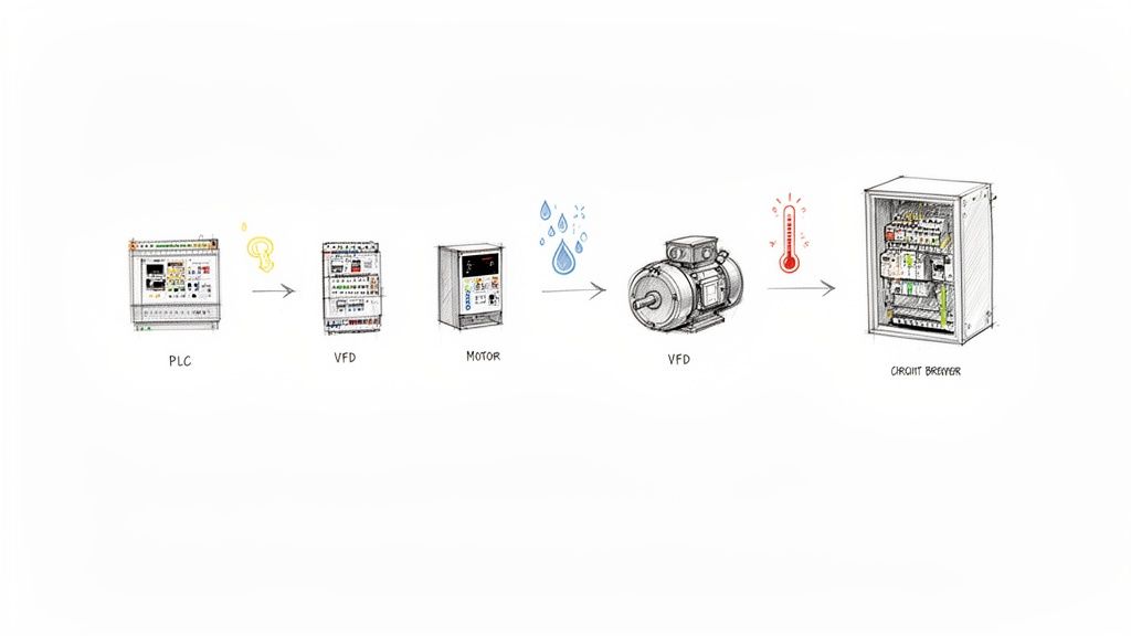
This infographic gives a great high-level view of the workflow, breaking it down into three main stages: concept, build, and commission.
As you can see, a solid plan is what makes a quality build possible, and a quality build is what ensures a smooth, efficient startup in the field.
The demand for these systems is exploding, and it’s a clear sign of a huge shift in the industry. The industrial control panels market was valued at USD 13.5 billion in 2023 and is on track to hit around USD 20.8 billion by 2032.
This isn't surprising when you see how much companies are leaning on automation to get more efficient. And if you’re looking to bring in an expert, knowing what to look for in a quality control panel builder is the perfect place to start.
Defining the Scope and Selecting Components
Every great control panel build starts long before you pick up a single tool. It begins with asking the right questions. Without a crystal-clear project scope, you're essentially flying blind, setting yourself up for expensive changes and delays down the road. A vague plan is a one-way ticket to a busted budget.
Think of it this way: you're defining the panel's entire reason for being. What machine is it running? What’s the exact I/O count for every sensor, valve, and motor? Nailing down these fundamentals is the bedrock of your design and component selection.
Groundwork Before the BOM
One of the most common rookie mistakes is forgetting about the environment. Is this panel going into a pristine, climate-controlled facility, or is it getting bolted to a machine in a washdown area where it'll see humidity and wild temperature swings? The answer changes everything, from the NEMA rating on the enclosure to whether you need an industrial air conditioner.
And then there's power. This is non-negotiable. What's the incoming voltage? What are the full-load amp (FLA) ratings for every single motor? This information is absolutely critical for sizing your breakers, contactors, and wiring correctly. Get this wrong, and you're not just risking equipment—you're creating a serious safety hazard.
As you get into the nitty-gritty, bringing safety into the conversation early is a must. A great way to do this is by understanding and implementing a risk register. This formal process forces you to identify potential electrical and mechanical hazards from the get-go, directly influencing your component choices to build a safer machine.
Making Smart Component Choices
Once you have a solid scope, you can start building your Bill of Materials (BOM). This is where the plan becomes a shopping list, and every line item is a decision that balances performance, cost, and availability.
Here’s a practical look at how these decisions play out when selecting key parts for your panel.
Key Component Selection Criteria
Component
Selection Criteria
Best Fit Application Example
Motor Starter
Simple On/Off control, lowest cost, reliable for fixed-speed applications.
A basic conveyor belt that just needs to run at a constant speed.
Soft Starter
Reduces mechanical shock and inrush current during startup.
A large centrifugal pump where a sudden start would stress pipes and couplings.
Variable Frequency Drive (VFD)
Full speed control, energy savings, precise process control.
A packaging machine that needs to vary motor speed for different product sizes.
Programmable Logic Controller (PLC)
I/O count, memory, processing speed, communication protocols.
An automated assembly line requiring complex logic and communication with a plant-wide network.
These are just a few examples, but they show how the application dictates the technology you need.
Take motor control. A simple conveyor might be perfectly happy with an across-the-line motor starter. But if you're building a packaging line that needs to vary its speed, a Variable Frequency Drive (VFD) is the only real answer. Somewhere in the middle is the soft starter—great for something like a large pump where you want to reduce the startup jolt but don't need full-blown speed control.
Then you have the brains of the operation: the Programmable Logic Controller (PLC). When sizing a PLC, don't just think about today. A good rule of thumb I always follow is to spec a PLC with at least 20-25% spare I/O capacity. This little bit of foresight can save you a world of pain when, a year from now, someone wants to add just one more sensor.
The real goal is to build a panel that not only works on day one but is also easy to service and adapt for years. Thinking about the future during the initial component selection is what separates a good panel from a great one.
The demand for well-engineered panels is exploding, right in line with the massive industry push toward automation. The global electric control panel market hit USD 6.37 billion in 2024 and is still climbing, all thanks to automation and grid modernization efforts. Automation panels are the fastest-growing piece of that pie, which tells you everything you need to know about where the industry is headed.
This growth means making smart component choices is more important than ever. Sticking with reputable brands known for reliability might cost a bit more upfront, but it almost always saves you money on maintenance and downtime later.
And one last pro tip: check supplier lead times early. A critical component with a 12-week lead time can completely torpedo your project schedule. This is where building solid relationships with a few good distributors really pays off—they can be lifesavers when you're in a pinch.
Designing Schematics for UL 508A Compliance
Once you have your components picked out, it's time to translate that physical plan into a detailed electrical design. This is so much more than just drawing lines on a page. You’re creating the definitive roadmap your panel shop technicians will follow to the letter.
A well-crafted schematic is, without a doubt, the single most important piece of documentation you will create for this project.
This is where safety and compliance, especially with UL 508A standards, really take center stage. These aren't just friendly suggestions; they're a hard requirement for getting your equipment to market and keeping operators safe in North America.
In fact, you can see the impact of these regulations just by looking at the market. The North American electric control panel market was valued at a cool USD 1.6 billion in 2023 and is on track to hit USD 2.8 billion by 2033. That growth is being pushed by more industrial automation and, you guessed it, strict safety rules. As the market grows, sticking to standards like UL 508A becomes non-negotiable.
The Core of Your Drawing Package
A truly complete drawing package is more than a simple wiring diagram. It’s a full-blown set of documents designed to leave zero room for guesswork. Think of it as the instruction manual for the panel's entire life, from the first wire being pulled to a maintenance call years down the road.
At a minimum, your package needs these four things:
Power Distribution Diagram: This is your 30,000-foot view. It shows how power comes in from the main disconnect and makes its way through every breaker, distribution block, and power supply to feed the whole system.
I/O Schematics: These are the nitty-gritty pages. They detail every single PLC input and output, the device it connects to, its terminal block number, and the wire tag. This is where a tech will spend their time when troubleshooting.
Network Layout: A clean map of your industrial network is a must. It should show how your PLCs, VFDs, and HMIs are all talking to each other. Always include device names and any critical network settings.
Panel Layout Drawing: This is the physical blueprint, showing exactly where every component gets mounted on the back panel and door. It’s what ensures the real-world build actually matches your electrical design.
I’ve seen it a hundred times: schematics that are technically correct but practically useless. A technician shouldn't need a magnifying glass and a decoder ring to figure out what you were thinking. Use clean layouts, consistent symbols, and text that’s actually legible.
Demystifying UL 508A Requirements
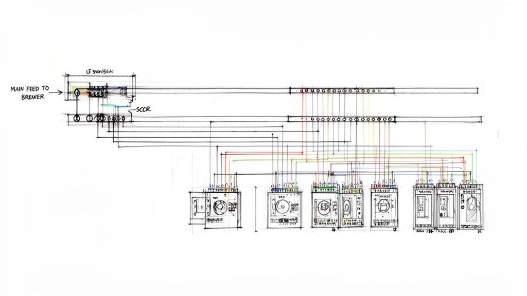
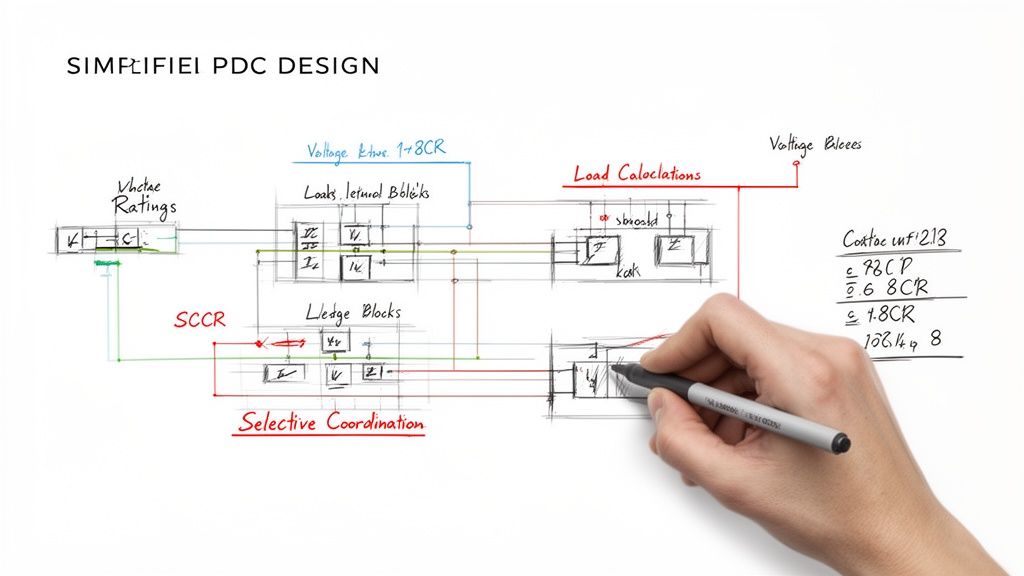
Diving into UL 508A can feel like a lot, but it really boils down to a few core principles that all point back to safety. One of the most critical—and honestly, one of the most frequently misunderstood—is calculating the Short-Circuit Current Rating (SCCR).
SCCR is the maximum fault current a panel can handle without turning into a fire or shock hazard. And it’s not just about your main breaker. The SCCR of the entire panel is determined by the lowest-rated component in the power path. Every single device, from the main disconnect down to the smallest terminal block, has an SCCR value that you have to account for. Getting this calculation wrong is one of the fastest ways to get a red tag from a UL inspector.
Another big one is component spacing. Things like VFDs and power supplies throw off a lot of heat. UL 508A has specific rules for how much clearance you need around these devices to make sure air can circulate properly. Skimp on this, and you’re asking for overheated components, premature failures, or worse, a fire.
Wire Sizing and Protection
Getting your wire sizing and circuit protection right is fundamental to a safe control panel build. This is no place for guesswork. You have to select wire gauges based on the full-load amperage (FLA) of whatever you're powering, and you need to account for real-world factors like ambient temperature and how many wires are bundled together.
Every circuit needs its own properly sized fuse or circuit breaker. A classic mistake I see is using a breaker that’s way too big for the wire it's supposed to be protecting. The protector’s job is to trip before the wire turns into a toaster element during an overcurrent event.
It’s also crucial to get the different component certifications straight. To keep everything compliant, you need to understand the nuances between UL Listed vs. UL Recognized components, because they each have a specific role in the panel's overall rating. Picking the right parts and protection from the start is the foundation of a safe, reliable, and compliant panel.
Building the Panel: Mechanical Layout and Wiring
This is where the rubber meets the road—where your schematics and component lists start to look like an actual control panel. Don't underestimate this step. A thoughtful mechanical layout is just as critical as your electrical design. I’ve seen brilliantly designed circuits become a nightmare to service simply because the panel was laid out poorly.
Think of your backpanel as prime real estate. Every square inch matters.
Before you drill a single hole, lay all your major components out on the backpanel. This dry run is your best chance to see how everything fits, spot potential interference, and visualize the wiring paths. You’re looking for a logical power flow, which usually means top-to-bottom and left-to-right. Your main disconnect sits at the top, feeding power distribution blocks, which in turn supply everything else—breakers, drives, and power supplies.
Optimizing Component Placement for Longevity
Where you put things directly impacts how long they'll last. Heat is the number one enemy of electronics, so your layout is your first line of defense against it.
A hard and fast rule is to place heat-generating components like Variable Frequency Drives (VFDs) and power supplies toward the top of the enclosure. Heat rises. Placing them high allows that heat to be exhausted by fans or vents without cooking everything else in the cabinet. Putting a VFD at the bottom is a rookie mistake that guarantees you'll be replacing the PLC above it sooner rather than later.
Here’s how I approach placing the key players:
PLC and I/O Modules: This is the brain of the operation. I like to position it centrally, keeping it as far as practically possible from high-voltage motor wiring. This separation is crucial for minimizing the electrical noise that can wreak havoc on your control signals.
Power Supplies: Group these with other hot components near the top. Pay close attention to the manufacturer's spec sheet for required clearances. Crowding a power supply and blocking its airflow is just asking for a thermal shutdown at the worst possible time.
Terminal Blocks: Group them logically. I create separate, clearly labeled zones for incoming power, motor outputs, and low-voltage I/O. It makes the initial wiring faster and saves massive headaches during troubleshooting down the line.
And please, plan for the future. A panel stuffed to the gills the day it’s built is a failure in planning. I always aim to leave at least 20% free space on the backpanel. The maintenance tech who has to add a new sensor six months from now will thank you for it.
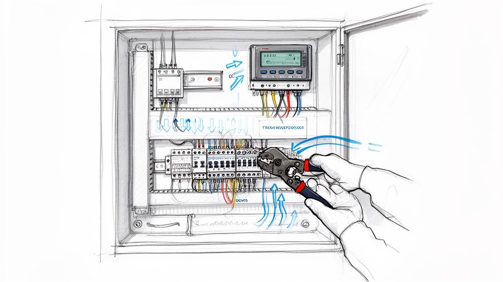
Professional Wiring and Cable Management
With all the hardware mounted, it's time to run the wire. This is what separates a professional control panel build from an amateur job. The goal isn't just connecting Point A to Point B; it's creating a clean, secure, and easily traceable installation.
The workhorse here is the wire duct. These plastic channels are non-negotiable for a clean build. They let you route wire bundles neatly and keep the panel from turning into a rat's nest. A key pro-tip: never fill a duct more than 75% full. Overstuffing it not only looks terrible but also traps heat and makes pulling a single wire for troubleshooting nearly impossible.
Secure terminations are just as critical. A loose wire is a future service call waiting to happen.
Proper Crimping: Use the right tool for the job. A high-quality crimper designed for the specific ferrules or terminals you're using is a must. Using pliers will get you a weak connection that will eventually fail.
Correct Torque: Terminal blocks have torque specs for a reason. Get a calibrated torque screwdriver and use it. Over-tightening can crack the terminal, while under-tightening creates a high-resistance spot that can overheat.
Strain Relief: Make sure any cables entering or leaving the panel are properly secured. This takes the physical stress off the terminal connections, especially for things that might get moved around like HMI pendants or remote sensors.
A panel’s quality isn't just in its function, but in its craftsmanship. When a technician opens the door five years from now, the layout and wiring should be so clear that they can understand the system's logic without needing to hunt through pages of prints.
The Critical Final Touches: Labeling and Grounding
Finally, let's talk about two things that are absolutely non-negotiable: labeling and grounding. Rushing or skipping these is one of the most expensive mistakes you can make in the long run.
Every single wire, terminal, and component needs a label. No exceptions. Invest in a good thermal transfer printer for durable wire tags that won't smudge or fall off. A clear, consistent labeling scheme that matches your schematics is the single most valuable thing you can do to speed up commissioning and future troubleshooting.
Proper grounding is the bedrock of a safe and reliable system. I always establish a central grounding point—a copper bar is ideal—and run dedicated ground wires from every single component back to it. This "star grounding" method is the best way to prevent ground loops and fight the electrical noise that can plague sensitive analog signals and communication networks.
Testing and Commissioning for a Smooth Handover
Let’s be honest: a control panel build isn't finished until it’s proven to work flawlessly. Shipping a panel without putting it through its paces is one of the biggest—and most common—gambles you can take. Trust me, discovering a simple wiring mistake on-site, with your client breathing down your neck, is a nightmare scenario. It's ten times more stressful and expensive to fix in the field than it is in your own shop.
This final phase is what separates the pros from the amateurs. Testing, documentation, and commissioning transform a collection of wired components into a bulletproof, field-ready system. It’s the final quality gate before the panel leaves your hands and the first step toward a successful project handover.
The Factory Acceptance Test: Your First Line of Defense
The Factory Acceptance Test (FAT) is your formal, in-house verification process. It's a systematic series of checks confirming the panel was built exactly to the drawings and functions as intended, before it ever leaves your facility. Think of a well-run FAT as your best insurance policy against on-site chaos.
It all starts with "dead" checks—no power allowed just yet.
Point-to-Point Continuity: Get out the multimeter. You need to buzz out every single wire to confirm it’s landed correctly per the schematics. It’s tedious, but this one step catches the vast majority of simple wiring errors. Don't skip it.
Insulation Resistance Test: You’ll want to megger the panel to check for shorts between conductors and from conductors to ground. This is a critical safety check to prevent a very bad, very loud surprise when you first apply power.
Torque Verification: Grab a torque wrench and double-check every single terminal. Loose connections are a ticking time bomb and a primary cause of heat-related failures down the road.
Only when these checks are complete is it safe to move on to live power-up testing. This is where you apply control power, then main power, to check voltages, verify power supply outputs, and see the components come to life. The final piece is I/O simulation, where you manually trigger inputs and watch for the correct outputs—lights, contactor coils, etc.—to energize just as the program commands.
A detailed FAT isn't just a technical task; it's a confidence-building exercise for your client. Inviting them to witness the test demonstrates transparency and proves that you're delivering a quality product, making the final handover much smoother.
From the Shop to the Site: Seamless Commissioning
Commissioning is where the rubber meets the road. It starts the moment the panel is installed at its final destination and gets integrated with the actual machine and process. The goal here is to get from initial power-up to a fully operational system as quickly and efficiently as possible.
The final trial is the Site Acceptance Test (SAT). While the FAT often relies on simulated I/O, the SAT uses the real deal—the machine's actual sensors, motors, and actuators. This is your chance to verify motor rotation is correct, confirm every sensor is functioning, and fine-tune operational parameters like VFD speeds or timer delays.
To clarify the distinction, here’s a quick breakdown of FAT vs. SAT.
Aspect
Factory Acceptance Test (FAT)
Site Acceptance Test (SAT)
Purpose
Verify panel is built and functions according to design specs.
Verify the panel and machine work together as a complete system.
Real-world I/O testing, motor rotation checks, system tuning.
A well-planned commissioning process, backed by a successful FAT and solid documentation, ensures the SAT is a final confirmation, not a frantic troubleshooting session. This smooth transition is the hallmark of a professional build and the key to a happy client.
The Power of a Complete Documentation Package
Once testing is complete, the final step is to assemble a comprehensive documentation package. This binder (or digital folder) is the panel's official "owner's manual." For the end-user's maintenance team, it will be an invaluable resource for years to come.
A truly great package always includes:
As-Built Schematics: The updated drawings reflecting any redlines or minor changes made during the build.
Bill of Materials (BOM): The final, verified list of every component, including manufacturer and part number.
Component Datasheets: The manufacturer's technical PDFs for every major item, like the PLC, drives, and power supplies.
Program Backups: A copy of the PLC and HMI programs on a USB drive tucked into the binder sleeve.
FAT Report: The signed-off checklist from the Factory Acceptance Test. This is your documented proof of a successful test.
Even with the best plan in hand, questions are going to pop up during a control panel build. It’s just the nature of the beast, especially when you're juggling complex safety standards and a dizzying array of components.
Getting ahead of these common sticking points can save you a world of hurt—and a lot of money—down the road. So, let's jump into some of the most frequent questions we hear from engineers and clients out in the field.
What Is the Most Critical Factor in a UL 508A Control Panel Build?
This is a big one. While everything from wire gauge to terminal torque matters, the single most critical piece of the puzzle is calculating the Short-Circuit Current Rating (SCCR) correctly.
This number defines the maximum fault current your panel can handle without, well, exploding or catching fire. It is the absolute, non-negotiable foundation of any UL 508A compliant panel and is paramount for personnel safety.
Failing to calculate SCCR properly is probably the number one reason we see panels get red-flagged during a UL inspection. The process is intense; it requires you to analyze every single power component, from the main breaker all the way down to the smallest contactor. The whole panel's rating is only as strong as its weakest link.
Getting SCCR right isn't just a box-ticking exercise for an inspector. It's about making sure that if the worst happens, the panel fails in a predictable and safe way. It truly is the bedrock of your panel's entire safety certification.
How Can I Improve the Serviceability of My Control Panel Design?
Making a panel easy to work on boils down to two things: a smart, logical layout and documentation that’s crystal clear. A panel that’s a nightmare to troubleshoot is a panel that won't get maintained properly, and that means more downtime later.
Here are a few practical tips we’ve learned over the years to make life easier for the technicians:
Leave Room to Grow: Always plan for the future. We live by a simple rule: leave at least 25% spare space on the back panel and on the DIN rails. This turns adding a new VFD or I/O slice from a full-blown rewiring project into a simple afternoon task.
Don't Jam the Ducts: A common mistake is packing wire ducts to the brim. Try to keep them at about 75% capacity. This not only helps with heat dissipation but makes it infinitely easier for a tech to trace a wire without having to pull out the whole bundle.
Label Everything. No, Really: Every component, every terminal block, and every single wire needs a clear, durable label. Crucially, these labels must match your electrical schematics perfectly. This creates a one-to-one map from paper to panel.
Use Service Loops: For anything mounted on the enclosure door—like your HMI or pushbuttons—leave a generous loop of wire. This prevents strain on the terminals when the door swings open and makes swapping out a faulty button a quick fix instead of a headache.
What Are the Key Differences Between Motor Starters?
Picking the right motor starter is all about matching the hardware to the job's demands for control, efficiency, and mechanical stress. You’ve basically got three main flavors to choose from.
Starter Type
Primary Function
Common Application
Across-the-Line (DOL)
The simplest option. It's just on/off control, hitting the motor with full voltage.
A basic conveyor belt that just needs to run at one constant speed.
Soft Starter
Ramps up voltage for a smooth, controlled start, reducing shock to the system.
A large pump or fan where a sudden DOL start would hammer the couplings or piping.
Variable Frequency Drive (VFD)
Controls both voltage and frequency for precise speed control during operation.
A packaging machine that has to adjust motor speed on the fly for different products or line rates.
Think of it this way: a DOL starter is your basic light switch. A soft starter adds a dimmer for a gentle start but offers no speed control once it’s running. A VFD gives you that gentle start plus complete speed regulation, which is fantastic for process control and saving energy.
Why Is a Factory Acceptance Test So Important?
A Factory Acceptance Test (FAT) is your final quality gate before the panel ever leaves your shop. It’s your chance to validate everything in a controlled environment, and trust me, it’s far cheaper and easier to fix a wiring bug or a programming glitch at your own facility than it is on a customer's floor with their entire production team watching.
A good FAT doesn't just find problems; it provides documented proof that the panel works exactly as promised. It drastically cuts down on commissioning time, builds a ton of confidence with your client, and makes the final on-site startup a much, much smoother process.
At E & I Sales, we've spent decades mastering the art and science of the control panel build. From initial design and UL 508A compliance to rigorous testing and commissioning, our team provides the expertise to deliver reliable, code-compliant solutions for any industrial application. Learn more about how our turnkey services can accelerate your next project at eandisales.com.
At its core, a motor variable speed controller is a device that fine-tunes the speed and torque of an electric motor by adjusting the electrical power feeding it. You can think of it like a dimmer switch for a light bulb, but instead of adjusting brightness, it gives you precise control over your motor's performance. It’s the difference between a simple on/off switch and a system that can run at the exact speed a job requires.
What Is a Motor Variable Speed Controller and Why You Need One
Imagine trying to drive a car that only has two modes: full throttle and park. That's essentially how many industrial motors run without a controller. They're either all on or all off, which is a brutally inefficient and mechanically jarring way to operate. This works for the simplest tasks, but it's incredibly wasteful for applications where the load changes, like a conveyor belt that needs to speed up or a fan that must adjust airflow.
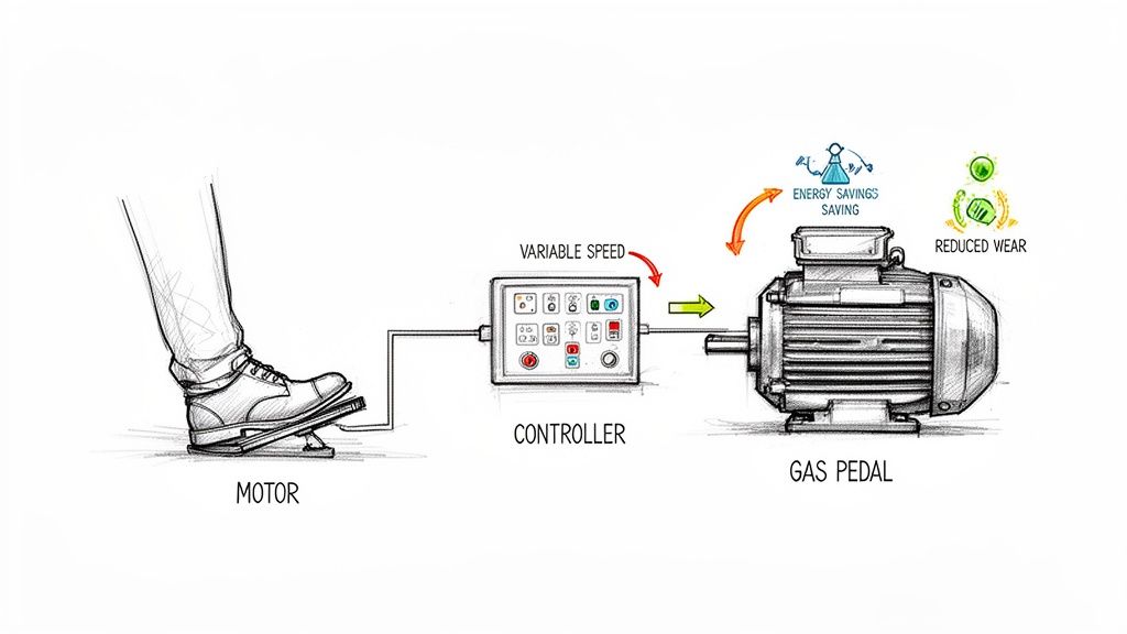
The motor variable speed controller acts as the "gas pedal" for your machinery. It solves the fundamental problem of using a fixed-speed motor for a variable-demand job. Instead of running a motor at 100% and then using a mechanical brake—like a damper or valve—to choke the output, the controller tells the motor itself to slow down. This elegantly matches the motor's work to the system's real-time needs.
The Strategic Value of Precision Motor Control
It's a mistake to see these controllers as just another component. They are a strategic investment that sends a ripple effect of improvements across your entire operation. The initial cost is almost always dwarfed by the long-term returns in energy savings and equipment health.
The most obvious win is a massive reduction in energy consumption. In many industrial settings, motors are the single biggest electricity hogs. By matching motor speed to the actual load, especially in common pump and fan applications, facilities can cut their energy use by as much as 50%.
By enabling motors to operate only as fast as necessary, a motor variable speed controller eliminates wasted energy, reduces mechanical wear, and provides the fine-tuned process control essential for modern industrial automation.
But the benefits go far beyond the power bill. These controllers bring a few other game-changing advantages to the table:
Extended Equipment Lifespan: The controller enables a "soft start," gently ramping up the motor's speed instead of slamming it on. This completely avoids the violent mechanical shock and huge electrical inrush current—which can spike to over 600% of the motor's rating—that comes with a direct-on-line start. The result is significantly less wear and tear on belts, gears, couplings, and the motor itself.
Enhanced Process Control: From bottling lines to chemical mixing, countless industrial processes demand exact speeds to get the product right. A controller delivers the precision needed to hold tight tolerances, reduce waste, and ensure every batch is consistent.
Improved System Reliability: By cutting down on mechanical stress and preventing motors from overheating, these controllers make the entire system more stable and dependable. That means fewer surprise breakdowns and less costly downtime.
Moving Beyond Mechanical Inefficiency
The old way of controlling motor-driven systems was purely mechanical and, frankly, crude. To reduce flow in a pumping system, an operator would have to physically close a valve partway, forcing the pump's motor to work against that restriction while still spinning at full speed.
Think about that for a second. It’s the exact same logic as flooring the accelerator in your car while simultaneously riding the brake to manage your speed. It's incredibly wasteful and puts a ton of unnecessary strain on every single component.
A motor variable speed controller provides a far more intelligent and direct path to control. By adjusting the motor's electrical input, it addresses the power at the source, making the whole operation more responsive and efficient. This move away from mechanical restriction and toward smart electrical regulation is a cornerstone of modern industrial performance.
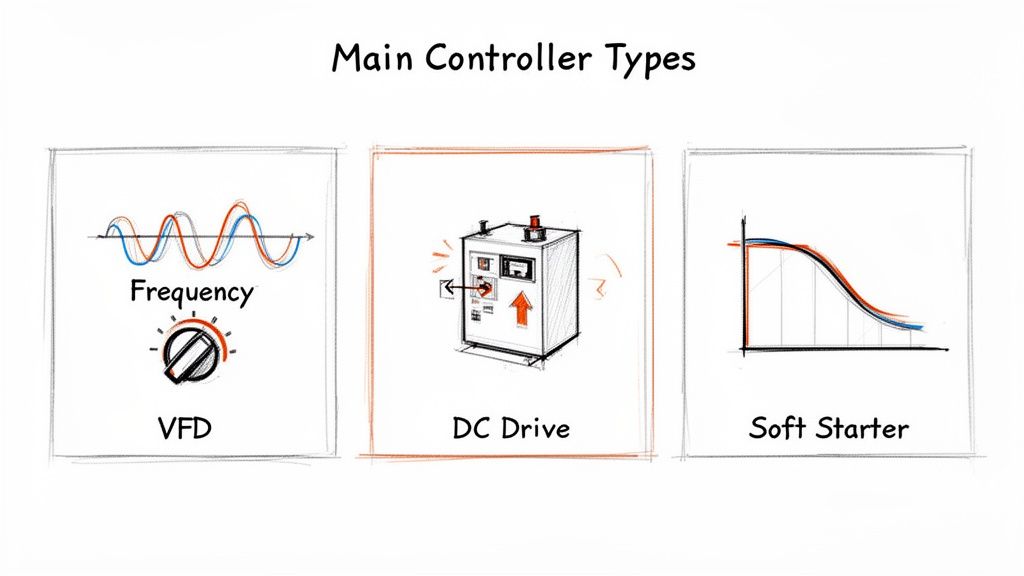
Exploring the Main Types of Motor Speed Controllers
When it comes to motor control, one size definitely does not fit all. Picking the right technology is critical for performance, efficiency, and the longevity of your equipment. Think of it like a mechanic's toolbox—you need the right tool for the job, and you wouldn't use a sledgehammer where a precision screwdriver is needed.
The world of motor control is dominated by three main players. Understanding what makes each one tick is the first step to making a smart choice for your application, whether you're running a simple conveyor or a complex, automated production line.
The Workhorse: AC Variable Frequency Drives (VFDs)
The Variable Frequency Drive (VFD) is, without a doubt, the champion of modern motor control. It's the most versatile and common solution out there, especially for the three-phase AC induction motors that are the backbone of most industrial machinery. A VFD gives you total command over a motor’s speed, from a dead stop all the way to full throttle.
How does it work its magic? A VFD performs a clever bit of electrical gymnastics. It takes the standard, fixed-frequency AC power from the wall (usually 60 Hz in North America), converts it into DC power, and then uses powerful transistors to chop that DC power back into a brand new, synthetic AC waveform. The kicker is that it can create this new waveform at any frequency you command.
The core principle is beautifully simple: an AC motor's speed is directly tied to the frequency of the power you feed it. By precisely dialing that frequency up or down, a VFD lets you run the motor at the exact speed your process needs.
This level of control is non-negotiable for applications that demand constant adjustment, like a pump maintaining steady pressure in a system or a fan modulating airflow for climate control. For a deeper dive, check out our comprehensive guide to AC motor variable speed.
Specialized Control With DC Drives
While AC motors run the show these days, don't count DC motors out just yet. They still have a firm foothold in niche applications where high starting torque and rock-solid speed control at very low RPMs are must-haves. That’s where the DC drive steps in.
DC drives operate on a different principle because they’re controlling a different beast. They regulate motor speed by simply adjusting the DC voltage sent to the motor's armature. More voltage means more speed, less voltage means less speed. It's a direct, responsive, and beautifully straightforward method of control.
You’ll still find DC drives hard at work in:
Legacy Equipment: A ton of older, tried-and-true industrial machines were designed around the rugged performance of DC motors.
Heavy-Duty Machinery: Think cranes, hoists, and extruders that need massive torque right from the get-go.
Precision Applications: The simple, direct control loop makes them a solid choice for certain high-precision tasks.
The Limited (But Important) Role of Soft Starters
A soft starter is often lumped in with VFDs and DC drives, but it’s crucial to understand it’s in a different category. A soft starter is not a speed controller. Its one and only job is to manage how a motor starts and stops.
When a big AC motor fires up directly across the line, it causes a huge electrical surge—often 6 to 8 times its normal running current—and a violent mechanical jolt. A soft starter acts like a shock absorber. It gently ramps up the voltage for a smooth, controlled start, then typically gets out of the way and lets the motor run directly off the line.
While it can't change the speed during operation, that gentle startup is invaluable. It drastically reduces mechanical and electrical stress, and it's not uncommon for a soft starter to extend a motor's life by 20-30%. This is why maintenance managers love them.
This focus on efficiency and equipment protection is driving major growth, especially in emerging markets. The electric vehicle motor controller market alone is projected to explode from $9.675 billion in 2025 to a staggering $47.04 billion by 2035.
VFD vs DC Drive vs Soft Starter At a Glance
So, how do you choose? It all boils down to what your application demands. A quick side-by-side comparison can make the decision crystal clear.
Controller Type
Primary Function
Best For
Key Benefit
AC VFD
Full-range speed control of AC motors by varying frequency and voltage.
Pumps, fans, conveyors, and any application requiring precise, continuous speed adjustments.
Maximum energy savings and complete process control.
DC Drive
Full-range speed control of DC motors by varying DC voltage.
Legacy systems, cranes, hoists, and applications needing high torque at low speeds.
Excellent torque control and responsive speed regulation.
Soft Starter
Controls only the start/stop acceleration and deceleration of an AC motor.
High-inertia loads like large fans, pumps, and compressors where speed control isn't needed.
Reduces mechanical stress and electrical inrush current, extending equipment life.
Ultimately, the VFD offers the most complete control, the DC drive excels in high-torque niches, and the soft starter is the specialist for protecting your equipment during startup. Matching the technology to the task is the key to a reliable and efficient system.
So, What's In It For You? Unlocking the Real-World Payoff
Enough with the technical jargon. Let's get down to brass tacks and answer the one question every plant manager or OEM really cares about: What will this do for my bottom line?
Putting a motor variable speed controller on your line isn't just swapping out a piece of hardware. It's a strategic play that starts a chain reaction of benefits, tackling some of the most stubborn headaches in any industrial facility—from runaway energy bills to equipment that dies way too soon.
The first thing you'll notice, and the one that gets the CFO's attention, is the dramatic drop in your power consumption. For most plants, motors are the hungriest things on the grid, often running full-tilt boogie whether they need to or not. It's like flooring the gas pedal in your car and using the brakes to control your speed. You'd never do it, but that's exactly how countless systems operate every single day.
Slashing Energy Costs by Working Smarter, Not Harder
A motor variable speed controller puts an end to that madness. Instead of cranking a pump to 100% and then choking it with a valve to cut back the flow, the controller just tells the motor to slow down. It’s simple, elegant, and the impact is huge, especially for anything that moves air or liquid, like pumps and fans.
This shift to smarter motor control is a big deal. The global market for Variable Frequency Drives (VFDs) is on track to hit $31.3 billion by 2025, which tells you just how essential they've become. While a standard fixed-speed motor hemorrhages energy when it's not running at full load, a VFD dials in the perfect voltage and frequency for the job at hand. This can cut electricity use by up to 50% in pump and fan systems—which, by the way, make up a mind-blowing 65% of all industrial motor applications. You can get more insights on this market trend and what’s behind it.
A variable speed controller matches the motor's muscle to the actual work needed. This simple change can turn one of your biggest operating expenses into a major source of savings, often paying for itself in less than two years.
For centrifugal loads, this relationship is governed by what we call the Affinity Laws, which creates an almost magical savings curve. A small drop in speed leads to a massive drop in power consumption. For instance, slowing a fan down by just 20% can slash its energy use by nearly half.
Making Your Equipment Last Longer
Beyond the energy savings, these controllers are like a spa day for your machinery. The single most violent event in a motor’s life is the "direct-on-line" start. It gets hit with a tidal wave of current and a mechanical jolt that rattles everything downstream. This constant shock therapy hammers the motor windings, bearings, belts, gears, and couplings.
A motor controller completely changes the game with a "soft start." It eases the motor up to speed gently, eliminating that electrical and mechanical shock. This smooth ramp-up and ramp-down drastically cuts wear and tear, meaning your equipment lasts longer and you spend a lot less time dealing with expensive, unplanned breakdowns.
Nailing Your Process Control and Product Quality
In so many processes, precision is everything. Whether you're mixing chemicals, extruding plastic film, or managing tension on a winder, your product quality lives or dies by your ability to hold exact speeds and torques. A variable speed controller gives you that fine-grained command to hit your targets, every single time.
This level of control gives you a few key wins:
Rock-Solid Consistency: Every batch gets made under the exact same conditions. No more variations, just better quality.
On-the-Fly Flexibility: Operators can tweak line speeds for different products or materials with the push of a button—no wrenches required.
Less Waste: By getting rid of sudden jerks and keeping things smooth, controllers mean less damaged product, fewer spills, and a smaller scrap pile.
And as a final bonus, by slowing motors down, these controllers make the plant a much quieter place to work. The reduction in mechanical noise from fans, pumps, and conveyors is often significant, lowering the racket and creating a safer, more comfortable environment for your team.
How to Select and Size the Right Controller for Your Application
Picking the right motor variable speed controller is far more than just grabbing a part off the shelf—it's a critical engineering decision. The wrong choice can spell disaster in the form of poor performance, chronic overheating, catastrophic equipment failure, and costly downtime.
Getting this right the first time is the only way to guarantee your system runs safely, efficiently, and reliably for its entire service life. It’s a process that goes way beyond matching horsepower. You have to dig into the motor's specs, understand the unique demands of the job it's doing, and consider the environment it will live in.
Matching the Controller to the Motor
First things first: the controller and the motor have to be a perfect electrical match. Think of it like pairing an engine with the right transmission—get it wrong, and you’ll have problems from the moment you turn the key. The best place to start is by grabbing the data right off the motor's nameplate.
Voltage: The controller’s input and output voltage ratings absolutely must match your facility's power and the motor's operating voltage. A mismatch here is a quick way to destroy one or both components.
Horsepower (HP) or Kilowatts (kW): The controller has to be rated to handle the motor's horsepower. You can always use a bigger controller on a smaller motor, but you can never, ever safely use an undersized controller.
Full-Load Amps (FLA): This is the number that truly matters. The FLA rating tells you the current the motor draws when it's working its hardest. Your controller's continuous current rating must be equal to or greater than the motor's FLA. No exceptions.
Always trust the Full-Load Amp (FLA) rating over horsepower when sizing a controller. Amps are the true measure of the work getting done, and it’s a much more accurate yardstick, especially with today's high-efficiency motors.
Understanding Your Application's Torque Needs
Once the electrical basics are covered, you need to think about the kind of work the motor is actually doing. Different jobs put wildly different demands on a motor, and it all comes down to torque. This is a crucial distinction that directly steers you toward the right controller.
We generally break applications into two camps:
Variable Torque: For these jobs, the torque needed changes as the speed changes. Think of fans, centrifugal pumps, and blowers. The faster they spin, the more torque they need to move more air or liquid. These loads are the perfect candidates for VFDs and offer the biggest opportunities for energy savings.
Constant Torque: Here, the application demands the motor's full rated torque no matter how fast or slow it's running. Conveyors, positive displacement pumps, extruders, and hoists are classic examples. They need consistent muscle to move heavy loads, even when just creeping along.
Knowing which camp your application falls into is non-negotiable. Controllers are often rated differently for variable and constant torque jobs, with constant torque applications demanding a beefier—and usually more expensive—unit. If you want to get into the weeds, you can learn more about how to perform a torque calculation for motor selection.
Don't Forget the Environment and Enclosure
Where is this controller going to live? A clean, air-conditioned electrical room is a world away from a dusty factory floor or an outdoor installation exposed to rain and snow. This is where NEMA (National Electrical Manufacturers Association) enclosure ratings are your best friend.
The enclosure is the controller's armor, protecting its sensitive electronics from dust, dirt, water, and corrosive chemicals.
NEMA 1: Your standard indoor enclosure for clean, dry locations.
NEMA 12: Steps it up to protect against dripping liquids and airborne dust.
NEMA 4/4X: Built tough for washdown environments, protecting against hose-directed water. The "X" in 4X means it also resists corrosion.
Choosing the right enclosure isn't optional—it's a fundamental requirement for safety and reliability.
This flowchart helps connect the dots, showing how your main goal—whether it's saving money, making equipment last longer, or improving your process—links directly to the benefits a controller can deliver.
As you can see, a single investment in the right controller pays dividends in multiple ways, aligning perfectly with your key operational goals.
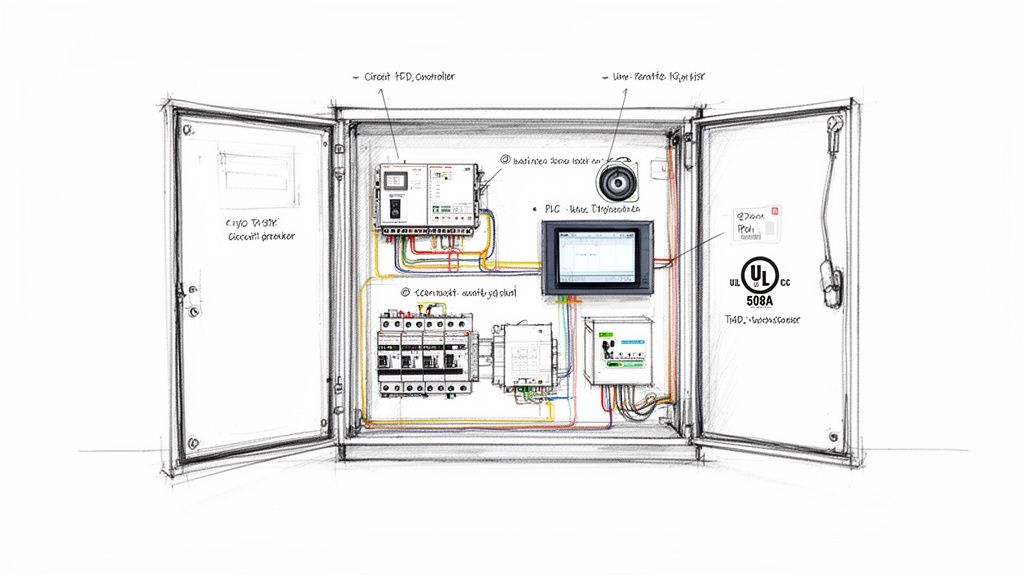
Integrating Controllers into UL-Listed Control Panels
A motor variable speed controller on its own is just one piece of the puzzle. A truly professional setup is a complete, integrated system. Just slapping a drive on the wall and running some wires is a surefire way to run into reliability issues and create serious safety hazards down the road.
That’s why proper integration into a purpose-built, UL-listed control panel is absolutely non-negotiable. It’s the only way to guarantee safety, meet electrical codes, and build a system that’s dependable for the long haul. This is what turns a pile of parts into a cohesive, turnkey solution ready to perform the moment you flip the switch.
More Than Just a Box: Key Panel Components
A professionally built control panel is engineered to house much more than just the controller itself. It brings together all the necessary support hardware—properly sized and wired—to protect both the equipment and the people operating it.
Inside a well-designed panel, you’ll find several critical components working in harmony:
Circuit Protection: This is your first line of defense. Fuses or circuit breakers are installed "upstream" from the controller to guard against short circuits and overcurrents, preventing a minor issue from turning into a catastrophic failure.
Disconnect Switch: A lockable main disconnect is a fundamental safety requirement. It allows technicians to completely de-energize the entire panel and follow lock-out/tag-out (LOTO) procedures before touching a single wire.
Line Reactors: Think of these as shock absorbers for your electrical power. Installed on the input side of the controller, these inductors smooth out the incoming voltage, shielding the sensitive drive electronics from spikes and cleaning up the harmonic distortion sent back to the grid.
Operator Interface: This could be as simple as a start/stop button and a speed knob or as sophisticated as a full-color Human-Machine Interface (HMI) touchscreen. It’s what gives operators on the floor the local control and monitoring they need.
Why the UL 508A Sticker Matters
When you see a UL 508A mark on a control panel, it’s not just a sticker—it’s a seal of approval that guarantees safety and compliance. This standard is the definitive benchmark for building industrial control panels in North America.
A UL 508A certification is proof that the panel was built by a certified shop using approved components, correct wiring techniques, and proper component spacing, all of which is documented and traceable.
A UL-listed panel buys you peace of mind. It signals to electrical inspectors, insurance companies, and your own safety team that the system has been thoroughly vetted against strict, nationally recognized standards for fire and electrical safety.
Choosing a UL-certified panel makes project commissioning smoother, simplifies regulatory sign-offs, and drastically reduces your liability. It ensures every single component is correctly sized, protected, and documented. For a deeper dive into what this entails, our complete guide to industrial control panel design has all the details.
Plugging Into Your Plant's Automation Brain
In any modern facility, a motor controller rarely acts alone. It needs to talk to the rest of your automation ecosystem, from the Programmable Logic Controllers (PLCs) that run the machine’s logic to the SCADA systems that give you a bird's-eye view of the whole plant.
This communication happens over industrial protocols. Standards like EtherNet/IP and Modbus act as the common language, letting the controller share critical data in real-time. This allows a central system to send speed commands, check the motor’s current draw, and instantly receive diagnostic fault codes.
This tight integration is the bedrock of modern process automation and the hallmark of a system delivered by an experienced partner who knows how to make all the pieces work together flawlessly.
Real-World Applications of Motor Speed Controllers
The real magic of a motor variable speed controller isn't just in the tech specs; it's what they do out in the field. These devices are the quiet workhorses in countless industries, saving massive amounts of energy, fine-tuning processes, and preventing the kind of wear and tear that leads to expensive downtime. You'll find them solving problems everywhere, from city infrastructure to sprawling factory floors.
Take HVAC systems and wastewater treatment plants, for instance. The pumps and fans in these places almost never need to run at 100% speed, 100% of the time. By using a controller to dial the motor speed up or down based on actual demand—like adjusting airflow as people move through a building or easing back on pump flow overnight—facilities can rack up some truly impressive energy savings. It's a huge deal in the HVAC world, which is why an HVAC sales representative often works closely with these technologies.
Enhancing Manufacturing and Logistics
In the world of manufacturing and logistics, it's all about precision and uptime. A conveyor system is the perfect example. Firing up a heavily loaded conveyor without a controller is like slamming your foot on the gas pedal. Products get jerked around, things get shifted out of place, and sometimes, stuff just falls right off.
A motor variable speed controller changes the game entirely. It delivers a smooth, controlled acceleration that protects both the products and the conveyor’s mechanical guts. It also gives you the power to perfectly sync up different parts of a production line, which is absolutely essential for keeping the whole operation running like a well-oiled machine.
Being able to fine-tune speed and acceleration isn't just a nice-to-have feature. It’s a core requirement for hitting quality targets and keeping things efficient in any modern automated facility.
Mastering Precision in Chemical Processing
For industries like chemical and plastics manufacturing, consistency is king. The slightest deviation from the recipe can ruin an entire batch. That's where controllers become indispensable for machinery like extruders and mixers.
Extruders: You need dead-on speed control to maintain the exact pressure and temperature required to produce materials with consistent thickness and quality.
Mixers: The ability to ramp motor speed up or down gives operators total control over the viscosity and homogeneity of a mixture, guaranteeing every batch is identical.
Centrifuges: Speed control is what allows for the precise separation of materials based on their density, a foundational process in tons of chemical and biological applications.
In these high-stakes environments, a motor variable speed controller provides the rock-solid torque and speed regulation needed to ensure product consistency, batch after batch. From bustling distribution centers to critical industrial processes, these controllers are the key to unlocking smarter, more efficient, and far more reliable operations.
Getting Your Questions Answered
When you're digging into the world of motor control, a few practical questions always seem to pop up. Let's tackle some of the most common ones we hear from engineers and plant managers out in the field.
Can I Slap a VFD on Just Any Old Motor?
You can, but you probably shouldn't. While a VFD will technically make a standard-duty motor spin, you're asking for trouble. It's always best to pair it with a true inverter-duty motor.
These motors are built differently. They have beefed-up insulation and often a shaft grounding ring designed to handle the punishing, high-frequency voltage pulses a VFD puts out. Using one prevents the kind of slow-burn damage—like fried windings and wrecked bearings—that can take a standard motor out of commission way too soon.
Seriously, How Much Energy Will I Save?
This isn't just marketing fluff; the savings can be massive, especially for certain applications. If you're running variable torque loads like centrifugal pumps or fans, the results are almost unbelievable.
The affinity laws tell the story: slow a fan's speed by just 20%, and you can slash its energy use by nearly 50%. This is where a motor variable speed controller really shines and pays for itself, often much faster than you'd expect.
While every system is unique, we see facilities get a full payback on their controller investment in under two years—sometimes purely from the drop in their electricity bills.
What's the Real Difference Between a VFD and a Soft Starter?
This is a big one, and getting it wrong can be a costly mistake.
Think of it this way: a VFD gives you full-range speed control, like a gas pedal for your motor. You can adjust the speed up and down anytime it's running. A soft starter, on the other hand, is more like a clutch. It only manages the motor's ramp-up and ramp-down to prevent the mechanical shock and electrical surge of a hard start. Once the motor is up to speed, the soft starter's job is done.
At E & I Sales, we don't just sell parts; we engineer complete motor control solutions. Whether you need a single drive or a complex, custom UL-listed control panel, we're the partners you can count on to get it right. If you're ready to select, size, and implement the perfect controller, let's talk.
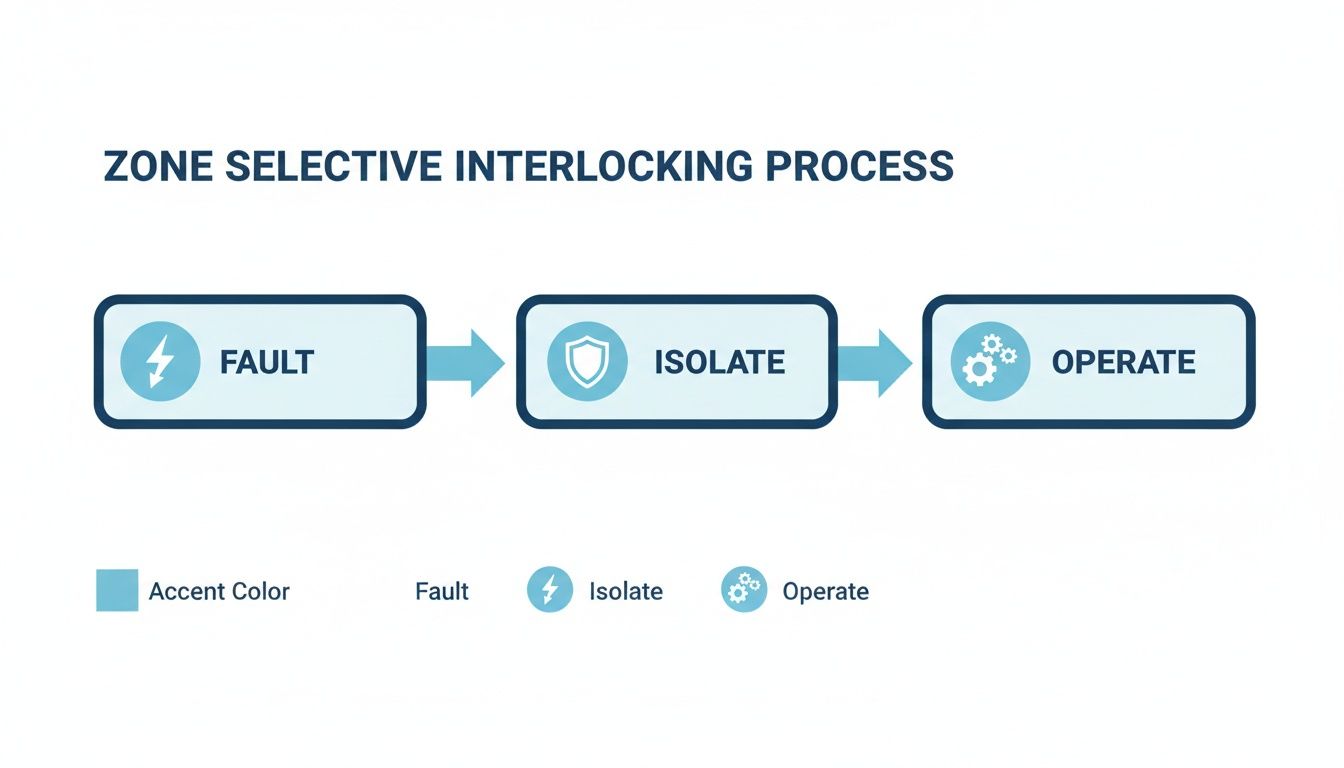
Picture this: a fire breaks out in a massive warehouse. Instead of every sprinkler in the building drenching the entire facility, only the ones directly over the flames kick on. That’s Zone Selective Interlocking (ZSI) in a nutshell. It's a smart communication system between circuit breakers that pinpoints and isolates a problem with surgical precision.
This simple idea solves one of the biggest headaches in power system design.
Solving the Protection vs. Selectivity Puzzle
For years, electrical engineers have been stuck in a trade-off between protection speed and system reliability. To keep a small fault on a branch circuit from tripping the main breaker and killing power to everything—a practice called selective coordination—we've had to intentionally slow down our upstream breakers. We program in time delays to give the device closest to the fault the first chance to open.
It works, but it comes at a steep price. The longer that fault is allowed to cook, the more destructive energy it unleashes. This dramatically increases the danger of a catastrophic arc flash. So you're left with a terrible choice: accept a higher arc flash risk to keep the lights on, or sacrifice uptime for faster, safer fault clearing.
Zone Selective Interlocking completely rewrites the rules, getting rid of that compromise. It establishes a high-speed communication link between breakers.
With ZSI, the breaker closest to the fault still trips instantly. But at the same time, it sends a signal "upstream" to the other breakers telling them to hold off. That simple "wait" command prevents a cascading outage and keeps the problem contained to the smallest possible area.
How ZSI Gives You the Best of Both Worlds
By enabling this kind of intelligent, localized response, ZSI delivers both lightning-fast tripping and rock-solid coordination. In the real world, this translates to huge benefits:
Massively Improved Safety: Clearing a fault in a few milliseconds instead of hundreds of them drastically cuts down the incident energy of an arc flash. This can be the difference between a minor event and a life-threatening one, often lowering the required level of Personal Protective Equipment (PPE).
Maximum Uptime: Say goodbye to nuisance trips that take out an entire production line or data center floor. ZSI ensures only the single affected circuit goes down, which is a massive win for operational continuity.
Less Equipment Damage: The faster you clear a fault, the less thermal and mechanical stress you put on your gear. That means less damage to cables, bus bars, and transformers, leading to faster repairs and lower replacement costs.
Essentially, ZSI transforms a rigid, pre-programmed protection scheme into a dynamic system that can think and react. It gives your power system the intelligence to know exactly where a fault is happening and to act only where needed. This capability has made ZSI a cornerstone technology for any modern industrial facility that values safety and reliability.
How Zone Selective Interlocking Actually Works
Let's stick with that fire sprinkler analogy. Now, imagine each sprinkler head couldn't just detect a fire, but could instantly text the main water valve: "Hold on, I see the flames here. I've got this." That’s pretty much the logic Zone Selective Interlocking (ZSI) brings to an electrical system.
At its heart, ZSI is a high-speed conversation between circuit breakers, all arranged in zones—from the main breaker all the way down to individual branch circuits. When a downstream breaker sees a fault, it doesn't just quietly prepare to trip. It simultaneously sends a tiny, instantaneous "blocking" signal to the breaker directly upstream.
This signal is a simple but powerful message: "I see the fault in my zone, and I am handling it." The local breaker then opens in milliseconds, clearing the fault with surgical precision. The upstream breaker, having received the signal, simply holds its position, maintaining its standard (and longer) time delay. It's now on standby, ready to act as a backup only if the first device fails to do its job.
The Communication Backbone
This intelligent conversation between breakers happens over dedicated wiring. The exact method really depends on the age and design of the switchgear you're looking at.
Hardwired Pilot Wires: In a lot of traditional setups, this is handled by a simple pair of low-voltage wires running directly between the electronic trip units of the breakers. It’s a direct, no-fuss, and incredibly reliable connection.
Internal Communication Buses: More modern "smart" switchgear often takes an integrated approach. Here, ZSI signals travel over an internal data bus—much like a small computer network—that connects all the breakers within the assembly.
This communication is the secret sauce. It’s what transforms a static, time-based protection scheme into a dynamic, responsive one.
The flowchart below shows just how simple and elegant this process is—a logical sequence that delivers both speed and selectivity.
Tracing the ZSI Signal Path
Let’s walk through a fault in a typical power distribution system to see ZSI in action. Imagine a dead short on a branch circuit feeding a large motor.
Fault Detection: The branch circuit breaker (we'll call it Breaker C) immediately senses the massive rush of current.
Signal Transmission: Instantly, Breaker C sends a "restrain" signal up to its feeder breaker (Breaker B). Breaker B gets the message and, in turn, passes a restrain signal up to the main (Breaker A).
Localized Trip: With its upstream neighbors now waiting patiently, Breaker C trips almost instantaneously—typically within 50 milliseconds—and isolates the fault right where it happened.
System Stability: Breakers A and B, having received their "hold" instructions, stay closed. Power to every other healthy circuit remains on, completely unaffected. That’s maximum uptime.
Now, what if Breaker C failed to trip for some reason? The restraining signal would stop. Breaker B would then see the fault, its own time delay would expire (say, at 200 milliseconds), and it would open as the next line of defense. This built-in backup function ensures the system stays protected, no matter what.
The "interlocking" logic is what makes the whole thing work so well. The upstream device’s action is literally locked based on the status of the downstream device. It’s a cooperative strategy that prevents cascading, widespread outages.
This coordination technique has been around for about four decades, but it really became a cornerstone of modern industrial safety as digital microprocessor breakers became the norm. Modern ZSI uses incredibly fast electronic signaling, which turns a traditional, slow time-graded system into something dynamic that dramatically cuts down on the thermal and mechanical stress equipment sees during a fault. For system designers, this means you can get incredible selectivity without having to compromise on speed or safety. You can learn more about how ZSI fits into modern power system studies on ETAP's product page.
Faster Tripping and Slashed Arc Flash Hazards
The engineering behind Zone Selective Interlocking is clever, but its real-world value is where things get exciting. It’s about safety and reliability. By turning a rigid, pre-programmed protection scheme into one that thinks and reacts, ZSI gets right to the heart of the biggest risks in power distribution.
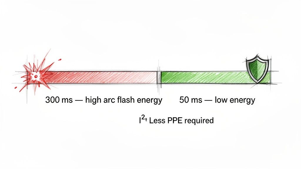
The single most critical benefit? A massive reduction in arc flash energy.
The destructive force of an arc flash boils down to a simple formula: energy equals current squared times time (I²t). You can't change the massive fault current available from the utility, but you absolutely can control the time component. That's ZSI's superpower—it allows the breaker closest to the fault to open almost instantly, dramatically cutting down the time the arc can burn.
A Tale of Two Clearing Times
Let's put some numbers on it. Picture a fault deep within a system that relies on traditional time-delay coordination. To avoid a nuisance trip, the main upstream breaker is intentionally set to wait, maybe for 300 milliseconds. That’s a long time for thousands of amps to be wreaking havoc.
Now, let's run the same scenario with ZSI enabled. The local breaker sees the fault, instantly signals the upstream breaker to hold off, and clears the fault itself—all in about 50 milliseconds.
That 250-millisecond difference is everything. It's the gap between a contained event and a catastrophic explosion that destroys switchgear and puts lives at severe risk.
The table below breaks down just how significant this time reduction is. By slashing the clearing time, ZSI directly lowers the incident energy a worker could be exposed to.
ZSI Impact on Fault Clearing Time and Arc Flash Energy
Scenario
Fault Location
Clearing Time (ms)
Incident Energy (cal/cm²)
Resulting PPE Category
Traditional Coordination
Motor Control Center Bus
300 ms
12.5 cal/cm²
Category 3
With ZSI Enabled
Motor Control Center Bus
50 ms
2.1 cal/cm²
Category 1
As you can see, dropping the trip time from 300ms to 50ms can easily reduce the required PPE from heavy, cumbersome suits to much lighter gear, making work safer and more efficient.
Keeping the Lights On and the Business Running
Safety is priority one, but ZSI also delivers a huge boost to the bottom line by maximizing uptime. In a conventionally coordinated system, a fault on a single motor feeder might be just slow enough to trip the main breaker for the entire MCC. Suddenly, an entire production line grinds to a halt over a localized problem.
ZSI stops these cascading outages cold. It makes sure only the device right next to the fault opens, leaving the rest of the facility online and productive.
For any plant manager or facility operator, uptime is money. Zone Selective Interlocking is a direct investment in operational continuity, protecting your revenue-generating processes from unnecessary and costly shutdowns.
This kind of surgical precision is priceless in factories, data centers, and hospitals, where every second of downtime costs a fortune. It elevates your protection scheme from a blunt instrument to a finely-tuned tool. Of course, technology is only one piece of the puzzle. The best-designed system still needs people who know how to work safely, which is why comprehensive https://eandisales.com/uncategorized/arc-flash-safety-training/ is non-negotiable.
This double-win of world-class safety and bulletproof reliability makes zone selective interlocking a must-have for any modern power system. It's not just about ticking a box for code compliance—it's about building an operation that is fundamentally safer, more resilient, and more profitable.
Alright, let's take that section on designing a ZSI system and give it a more hands-on, expert feel. Moving from the theoretical "what is ZSI" to actually building one that works is where the rubber really meets the road.
Designing and Implementing a ZSI System
Moving from a drawing board concept to a real-world, reliable Zone Selective Interlocking system is all about sweating the details. It really boils down to three make-or-break pillars: picking the right hardware, getting the settings dialed in perfectly, and making sure the wiring is flawless. Get these right, and you've built a powerful safety net. Get them wrong, and you've just got a diagram and a false sense of security.
The whole thing starts with the protective devices themselves. You can't just grab any old breaker off the shelf; they need to be built for this. Specifically, their electronic trip units must have the dedicated input and output terminals to send and receive those critical "hold off" signals.
Selecting Compatible Hardware
When you're putting together a bill of materials, you have to be certain that every device in the chain—from the main service entrance down to the feeder breakers—can speak the same ZSI language.
Breaker and Relay Compatibility: Make sure every single breaker and protective relay you specify is ZSI-enabled. It's sometimes possible to mix and match brands, but that means you'll be spending a lot of time buried in technical manuals to confirm they'll actually talk to each other. For anything complex, sticking with a single manufacturer's product family is often the path of least resistance.
Trip Unit Smarts: The electronic trip unit is the brain of this whole operation. You need to confirm it allows you to adjust the short-time pickup (Isd) and, most importantly, the short-time delay (tsd). These are the very settings ZSI manipulates.
Zone Limits: Dig into the manufacturer's spec sheets to see how many ZSI zones a single breaker can handle. Trying to make a device manage more zones than it was designed for is a recipe for unreliable performance.
If you're looking to spec a new system or upgrade an old one, it’s always a good idea to see what the established brands are offering. You can get a good sense of modern capabilities by checking out guides on specific gear, like a detailed overview of an ABB circuit breaker.
Configuring Settings and Coordination
With your hardware picked out, the real engineering begins: programming the settings. This is driven by a coordination study, and your Time-Current Curves (TCCs) are your best friend here. TCCs let you see exactly how your breakers will behave and interact when a fault hits.
The trick is to set up your short-time delays for proper coordination as if ZSI didn't exist. Think of it as your failsafe. For instance, a downstream breaker might get a 100 ms delay, while its upstream parent gets a 300 ms delay. With ZSI active, the system bypasses that built-in delay for the breaker closest to the fault, letting it trip in, say, 50 ms, while telling the upstream breaker to hold back.
A core philosophy in ZSI design is to first build a solid, traditional time-based coordination scheme. ZSI then acts as an intelligent accelerator, giving you incredible speed without sacrificing the fundamental backup protection of your staggered delay settings.
Critical Wiring and Verification
The physical wires connecting your devices are the nervous system of your ZSI scheme. The best breakers and the most brilliant settings mean absolutely nothing if the signal can't get through cleanly. Honestly, this is where most implementations go sideways.
Key Wiring Considerations:
Dedicated Cabling: ZSI signals need their own dedicated, twisted-pair shielded wire. This is non-negotiable. You have to shield the signal from the electrical noise and interference blasting off nearby power cables, which could easily corrupt it.
Correct Polarity: The ZSI input and output terminals are polarized. Getting them backward is a classic, easy-to-make mistake that completely defeats the system because the restraining signal will never be recognized. Double- and triple-check the polarity against the manufacturer's diagrams.
Current Transformer (CT) Selection: The breaker's trip unit is only as smart as the information it receives. That information comes from the CTs. Make sure your CTs are sized correctly for both the normal load and the potential fault currents. And just like the signal wires, their polarity has to be right, or the breaker could completely misinterpret what's happening during a fault.
By locking down these three areas—hardware, settings, and wiring—you can build a Zone Selective Interlocking system that you can truly count on. It’s this disciplined approach that ensures the system will do its job when the worst happens, protecting both people and equipment.
Testing and Troubleshooting Your ZSI Scheme
A perfectly designed Zone Selective Interlocking scheme on paper means nothing until it's proven in the field. Commissioning and testing aren't just a final checkbox; they are the critical steps that turn a safety blueprint into a real-world, reliable asset. This is where you validate that every wire, setting, and signal will do its job when a fault finally happens.
Think of it like inspecting a parachute. You trust the engineering, but you still meticulously check every strap and cord before the jump. For ZSI, this means running through static checks before power-up and then dynamic functional tests to confirm the whole system talks to each other correctly. Cutting corners here is simply not an option.
Pre-Energization Checks and Verification
Before you even think about energizing the system, a few methodical checks can catch over 90% of the most common installation mistakes. These are the basics, but getting them right prevents a world of headaches later.
Wiring Continuity and Polarity: This is ground zero for ZSI issues. Grab a multimeter and verify point-to-point continuity on all ZSI control wiring. More importantly, double-check the polarity of the ZSI input and output terminals against the manufacturer's drawings. Reversed polarity is an incredibly easy mistake to make, and it completely disables the interlocking logic.
Settings Verification: Get the coordination study in hand and physically walk down every breaker. You need to verify that the short-time pickup and delay settings on each trip unit match the engineered values to the letter. A single digit off can throw the entire coordination scheme out the window.
Insulation Resistance Testing: A quick "Megger" test on the ZSI control wiring is a must. This will tell you if there are any nicks or breaks in the insulation that could cause shorts or grounds, leading to phantom signals or a complete loss of communication.
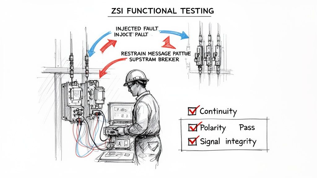
Functional Testing with Injection Sets
Once the static checks are done, it's time to make the system prove itself. We do this safely with a secondary current injection test set. This nifty tool essentially tricks the breaker's brain into thinking it sees a massive fault current, all without putting the actual power system at risk.
The whole point here is to trace the "restraining" signal's journey from start to finish. You'll inject a simulated fault current into a downstream breaker and watch for two things:
The downstream breaker trips instantly (or on its own short-time setting), just as it should.
The upstream breaker gets the restraining signal and successfully holds for its full coordinated time delay, proving the ZSI logic is working.
This functional test is the moment of truth. It goes beyond checking individual components and confirms that the entire ZSI system—breakers, wiring, and settings—operates as one cohesive, intelligent unit.
Common Troubleshooting Scenarios
Even the most carefully planned installations can hit a snag. When a functional test doesn't go as expected, the problem almost always boils down to just a handful of common issues. A methodical approach is your best friend here. If you need a refresher on the basics, understanding what can cause a breaker to trip provides some great foundational context.
To help you get straight to the root cause, here’s a quick-hit checklist for troubleshooting common ZSI symptoms.
Common ZSI Troubleshooting Checklist
Symptom
Potential Cause
Diagnostic Step
Solution
Upstream breaker trips instantly (doesn't hold)
Lost restraining signal due to wiring issue
Verify continuity and polarity of ZSI control wiring between the downstream and upstream breakers.
Physically verify the ZSI function is enabled and the short-time delay is set per the coordination study.
Adjust trip unit settings to match the engineered values.
Upstream breaker holds, but downstream breaker doesn't trip
Test current is below downstream breaker's pickup setting
Confirm the injected current from the test set is high enough to exceed the downstream breaker's short-time or instantaneous pickup threshold.
Increase the injected test current to the proper level.
All breakers trip simultaneously (no selectivity)
ZSI function is disabled on all breakers
Check the trip unit settings on each breaker involved in the scheme to ensure ZSI is turned on.
Enable the ZSI feature in the trip unit's programming menu.
Intermittent or unreliable restraining
Damaged control wiring or loose connection
Perform an insulation resistance test (Megger) on the ZSI wiring and physically inspect all terminal block connections for tightness.
Replace damaged wiring or re-torque loose terminal screws.
If an upstream breaker is tripping too fast, it's a clear sign the restraining signal isn't getting through. Start with the simplest and most likely culprits—the wiring—before you start digging into more complex device settings. This structured approach will save you time and lead to a more reliable fix every time.
ZSI on the Factory Floor: Real-World Applications
Theory is one thing, but putting it to work on the factory floor is where Zone Selective Interlocking (ZSI) really shines. It's a clever concept, for sure, but its real power is in solving tangible safety and uptime problems, especially in the systems that drive heavy industrial machinery.
You see this most clearly in Motor Control Centers (MCCs). Think of an MCC as the nerve center for an entire production line. A single fault on one motor feeder can easily bring everything to a grinding halt. Let's walk through a common scenario: a manufacturing plant is installing a brand new, UL-listed 480V MCC.
Without ZSI, if a big motor feeder shorts out, the main breaker for the whole MCC has to sit and wait. It's programmed with a long delay to try and coordinate with the downstream breakers. That delay might stop the whole plant from going dark, but it also allows a huge amount of dangerous arc flash energy to build up, often forcing anyone nearby into bulky Category 3 or 4 PPE.
A Case Study in Smarter Safety and Uptime
Now, let's say the engineers on this project decided to implement ZSI in their new MCC. This simple decision completely changes the outcome.
When a fault happens on a motor starter, the feeder breaker trips almost instantly—we're talking under 50 milliseconds. At the exact same moment, it fires a restraining signal up to the main MCC breaker, telling it, "Stand down, I've got this."
The result? A massive reduction in incident energy on the main bus. The arc flash danger is completely contained to the specific faulted bucket. The calculated energy level plummets, often making it safe enough for technicians to work with much less restrictive PPE. It’s a win-win: safety gets a huge boost, and you avoid tripping the entire MCC offline for a localized problem.
This shift from a slow, time-based coordination scheme to a fast, communication-based one isn't just an abstract concept. It's a practical, real-world solution that proves ZSI is a critical tool for modern industrial safety and reliability.
Taming Those Big Motor Inrush Currents
Here’s another place ZSI is a game-changer: dealing with large motors. When a big motor kicks on, the massive inrush current it draws can look a lot like a short circuit to a standard breaker, causing nuisance trips. To get around this, engineers sometimes have to dial back the protection settings to let the motor get through its startup phase, which unfortunately compromises safety.
ZSI provides a much more elegant answer. You can tune the system to intelligently ignore the predictable, brief surge of an inrush current but still react instantaneously to a genuine short circuit. This gives you bulletproof protection when the motor is most vulnerable, all without the headache of costly false trips that shut down production.
Even after getting the hang of Zone Selective Interlocking, you're bound to have some practical questions when it's time to put it to work. We see it all the time—engineers, maintenance managers, and facility operators need to balance the big safety wins with the real-world headaches of getting it done.
This section cuts straight to the chase, answering the most common questions we hear about cost, compatibility, and what happens when things go wrong. Let's clear up any confusion so you can feel confident about using ZSI to make your electrical system safer and more reliable.
Can I Retrofit ZSI Into My Existing Switchgear?
That’s the million-dollar question, isn't it? The answer is a solid "it depends." Retrofitting zone selective interlocking is definitely possible, but it all comes down to what kind of circuit breakers you're working with. The one non-negotiable is that your breakers need electronic trip units with dedicated ZSI input and output terminals.
If your switchgear is packed with old-school thermal-magnetic breakers or even basic electronic ones, this isn't a simple wiring project. You’d be looking at a full-blown replacement of the breakers with modern, ZSI-ready models. But if your gear already has compatible breakers, just adding the control wiring is a relatively simple upgrade that delivers a huge jump in safety.
What Happens If a ZSI Signal Wire Fails?
This is one of the most important things to understand from a safety perspective. Any properly designed ZSI system is built to be fail-safe. If a signal wire gets cut, comes loose, or shorts out, that communication link between breakers is broken. When that happens, your system doesn't just go dark—it automatically reverts to its standard, time-delayed coordination.
The upstream breaker simply never gets the "hold off" signal from the downstream device that saw the fault. So, it does what it's programmed to do: it trips based on its own short-time delay settings, ensuring you still have reliable backup protection. The system defaults to being slower, but it never defaults to being unsafe.
This built-in safety net means a simple wiring problem won't leave your people or equipment exposed. The worst-case scenario is that you lose the speed of ZSI, not the protection itself.
How Does ZSI Compare to Other Arc Flash Methods?
ZSI is a fantastic tool, but it's just one tool in the arc flash mitigation kit. It’s important to know where it shines compared to the other options out there.
Arc-Resistant Switchgear: Think of this as a brute-force solution. It’s designed to physically contain and redirect the explosive energy of an arc blast. It's incredibly effective at protecting people standing in front of the gear, but it's a major capital investment and does nothing to reduce the actual incident energy.
Maintenance Mode Switches: These are temporary overrides that let a technician manually set a breaker to trip faster while they work. They work well, but they are 100% dependent on someone remembering to flip the switch on and off. Human error is a real risk.
Optical Arc Detection Systems: Using light sensors, these systems can spot an arc flash and send a trip signal in just a few milliseconds. They are the absolute fastest solution available, but they are also the most complex and expensive to install.
Zone selective interlocking hits that sweet spot right in the middle. It's an active, full-time system that slashes incident energy without the high cost and complexity of optical systems, making it one of the most practical and cost-effective arc flash reduction strategies you can implement.
At E & I Sales, we live and breathe this stuff. We design and build custom UL-listed control panels and motor control centers with advanced protection like ZSI baked in from day one. We’re here to help you sort through the technical details and make sure your systems are safe, dependable, and up to code. Ready to talk about your next project? Contact us today and see what our expertise can do for you.
Think of a Power Distribution Center (PDC) as the heart of an industrial operation's electrical system. It’s a complete, factory-built assembly designed to take the high-voltage power coming into your facility and safely tame it, transforming and directing it to all the machinery that keeps your plant running.
In short, a PDC gives you a single, protected, and manageable control point for your entire operation’s power needs.
The Core Role of a Power Distribution Center
Picture a complex manufacturing plant. You’ve got dozens—maybe hundreds—of motors, pumps, conveyors, and sophisticated control systems. Without a PDC, trying to power everything would be a nightmare. You’d have a chaotic web of individual connections, each with its own safety risks and maintenance headaches.
This is exactly the problem a Power Distribution Center solves, and it does it with an elegant simplicity.
A PDC taps into a single, high-voltage feed from the utility and acts like a highly sophisticated traffic controller for that electricity. Safely tucked inside its rugged enclosure, transformers step the voltage down to usable levels for your equipment. From there, switchgear and circuit breakers safely route that power out to various loads, simplifying the entire electrical architecture of a plant or equipment skid.
Let's break down the essential jobs a PDC handles.
Core Functions of a Power Distribution Center
Here's a quick look at the primary roles a PDC plays and why they matter for day-to-day operations.
Function
Description
Impact on Operations
Voltage Transformation
Steps down high-voltage utility power (e.g., 13.8kV) to lower, usable voltages (e.g., 480V) for machinery.
Eliminates the need for multiple, separate transformers scattered across the plant, simplifying infrastructure and maintenance.
Centralized Distribution
Provides a single, organized hub for routing power to all downstream equipment, from motors to control panels.
Prevents hazardous "spaghetti wiring" and creates a logical, easy-to-trace power map of the facility.
Overcurrent Protection
Uses circuit breakers and fuses to instantly interrupt power during faults like short circuits or overloads.
Protects expensive equipment from catastrophic damage and prevents small issues from cascading into facility-wide blackouts.
Safety and Isolation
Consolidates disconnects into one location, allowing technicians to safely de-energize equipment for maintenance.
Drastically improves worker safety, simplifies Lockout/Tagout (LOTO) procedures, and reduces the time needed for repairs.
Ultimately, a PDC brings order, safety, and reliability to what would otherwise be a dangerously complex system.
Centralizing Power Management
The most obvious win you get from a PDC is centralization. Instead of hunting down dozens of disconnects spread across a massive facility, your team has a single source of truth for power. This alone makes troubleshooting, routine checks, and overall power management worlds easier.
This centralized approach brings a few key advantages:
Simplified Lockout/Tagout: When it's time for maintenance, having a single main point of disconnection makes safety procedures faster and far more reliable.
Streamlined Monitoring: Centralized metering gives plant managers a bird's-eye view of energy consumption for the entire operation, all from one dashboard.
Organized Distribution: It enforces a logical and orderly way to route power, getting rid of the tangled, hazardous wiring that plagues older or poorly planned facilities.
By bringing everything together, a PDC creates a more organized, safer, and predictable electrical environment. This structure is the foundation for preventing overloads and slashing unplanned downtime.
Protecting People and Equipment
Beyond just keeping things tidy, a Power Distribution Center’s most critical job is protection. It stands as a formidable guardian against the electrical faults that can destroy expensive machinery and, more importantly, endanger your people. It's designed to isolate problems at the source before they can ripple through the entire system.
A fault in one area shouldn’t shut down your entire operation, and a well-designed PDC ensures it won’t.
A well-designed power distribution center is the bedrock of operational uptime. By isolating faults and protecting equipment, it directly translates into improved reliability, increased production, and a stronger bottom line.
This protective role means the PDC has to work in harmony with all the downstream equipment it feeds. For instance, a PDC supplies the main power to other critical components, and you can learn more about how a Motor Control Center fits into this system.
At the end of the day, this integrated approach ensures that every single component—from the main incoming line to the final motor—is protected. That robust, end-to-end protection is the backbone of any reliable and profitable industrial operation.
What's Inside a Power Distribution Center?
To really get what a power distribution center does, you have to look under the hood. It’s way more than just a big metal box. A PDC is a highly engineered system where every single component has a job to do. I like to think of it like a city's power grid in miniature—it has a main power plant, substations, and local circuit protection, all working in concert to get electricity where it needs to go safely and reliably.
Let's trace the path of power, starting from where the high-voltage feed comes into the enclosure. This journey shows exactly how raw, untamed utility power is stepped down, routed, and safeguarded before it ever gets to your critical equipment.
This diagram neatly sums up the three primary functions of a PDC.
As you can see, the real value of a PDC is its ability to centralize control, protect your assets, and manage the entire electrical flow from one strategic point.
The Main Disconnect and Transformer
The whole process starts at the main incoming disconnect or circuit breaker. This is the big red button for the entire PDC, letting technicians kill the power to the whole system for safe maintenance or emergency shutdowns. It’s your first line of defense and the master switch for everything downstream.
Right after the disconnect, you'll find the transformer, which is the real workhorse of the system. Industrial plants often get fed with some serious high-voltage power (like 13,800 volts), which would fry most equipment instantly. The transformer’s job is to "step down" this voltage to something usable, which is typically 480/277V in most industrial settings.
You can think of the transformer like a pressure regulator in a high-pressure water main. It takes immense, unusable force and dials it back to a safe and manageable level for all the smaller pipes and faucets. Without it, your motors, drives, and control panels wouldn't stand a chance.
Switchgear and Busbars: The Power Highways
Once the voltage is at a usable level, that power has to get distributed. That’s where switchgear and busbars come in. If the transformer is the pressure regulator, then busbars are the massive, multi-lane superhighways that carry the electrical current throughout the PDC.
These thick, solid bars of copper or aluminum are much better at handling heavy current loads than conventional wiring could ever be.
The design of the busbar system is fundamental to the PDC's capacity and reliability. Proper sizing and bracing of these "electrical highways" directly determine the unit's short-circuit current rating (SCCR), a critical safety metric.
Bolted onto these busbars is the switchgear—an assembly of circuit breakers and switches that act like on-ramps and off-ramps on our power highway. They safely channel electricity from the main busbars out to smaller feeder circuits, which then go on to power individual machines, control panels, or motor control centers.
Circuit Breakers and Metering Devices
Every one of those feeder circuits has its own circuit breaker for protection. These are the smart, fast-acting safety guards of the PDC. Their one and only job is to watch the current flowing through them and, if they detect an overload or a dead short, to trip instantly and cut the power.
This is what stops a single malfunctioning motor from tripping the main breaker and shutting down your entire plant. Depending on the application, you'll see different kinds of breakers, from basic thermal-magnetic ones to sophisticated electronic trip units that give you incredibly precise control and feedback.
Finally, we have the metering devices, which are basically the PDC's dashboard. These instruments give you a real-time look at critical data, including:
Voltage and Current: Are your power levels stable and within spec?
Power Factor: How efficiently is your facility using electricity?
Energy Consumption (kWh): Where is your power going, and how much is it costing you?
This information isn't just nice to have anymore; it's absolutely essential for smart maintenance and operational efficiency. By keeping an eye on these numbers, engineers can spot problems like voltage sags or harmonic distortion long before they cause a catastrophic failure. This turns the PDC from a passive electrical box into an active, manageable asset that helps keep your facility running smoothly.
How to Design and Specify Your Power Distribution Center
Putting together a power distribution center is so much more than just connecting a few wires. It's about engineering the electrical backbone for an entire operation—one that’s safe, efficient, and built to last. When you get the specs right from the start, you sidestep costly mistakes, slash potential downtime, and build a system that can handle not just today's needs, but tomorrow's growth, too.
It all comes down to a methodical approach. You have to start with the most basic question: how much power does all your equipment actually need? From that single point, every other decision—from voltage ratings to grounding schemes—falls into place to create a truly reliable system.
Nailing Down Load Requirements and Voltage Ratings
Your first move is always a detailed load calculation. This means listing out every single piece of equipment that will pull power from the PDC—motors, heaters, control panels, lights, you name it—and adding up their power demands. It's absolutely critical to account for both the constant, steady loads and the big, power-hungry machines that only kick on intermittently.
One of the most common trip-ups we see is underestimating future needs. A solid rule of thumb is to build in a 20-25% capacity buffer on top of your total calculated load. That extra headroom gives you the flexibility to add more equipment later without having to rip and replace the entire PDC.
With a clear picture of your load, you can pin down the right voltage ratings. This is usually dictated by the incoming utility service and the demands of your biggest motors or machines. A very common setup in industrial plants is stepping down a medium-voltage feed (say, 13.8kV) to a much more usable 480V for the three-phase motor loads on the floor.
Understanding Short-Circuit Current Ratings (SCCR)
Once you've got the basic load and voltage sorted, the conversation has to turn to a critical safety metric: the Short-Circuit Current Rating (SCCR). In simple terms, SCCR is the maximum amount of fault current a component can handle without failing catastrophically—as in, exploding or catching fire.
Think of it as the system's ability to withstand an electrical hurricane. A low SCCR is like building a house that can't handle high winds. When a fault hits, the results are disastrous.
The SCCR of your entire power distribution center is only as strong as its weakest link. Every single component—from the main breaker down to the smallest terminal block—must be rated to handle the available fault current at its specific location.
Figuring out the available fault current from the utility transformer isn't just a good idea; it's a non-negotiable step. That number determines the minimum SCCR you need for your main protection device and has a domino effect on the ratings for everything downstream, creating a fully coordinated and safe system.
The Critical Role of Selective Coordination
Selective coordination is a smart design strategy that can make a world of difference in your plant's reliability. Imagine this: in a system without coordination, a short circuit on a tiny branch circuit—like a single motor—could trip the main breaker and shut down the entire facility. That’s a massive, costly headache.
Selective coordination is the fix. It ensures that only the breaker closest to the fault is the one that opens. So, if that one pump motor fails, its dedicated breaker trips, but the rest of the plant keeps humming along without interruption.
You achieve this by carefully choosing breakers with specific trip curves and time-delay settings. The breaker downstream is always set to react faster than the one upstream, creating a clear and precise protective hierarchy. This isn't just a "nice-to-have" feature; it's often a code requirement for critical infrastructure like emergency and life-safety circuits.
Grounding Strategies and Metering Integration
Proper grounding is the bedrock of electrical safety. Period. It gives fault currents a safe, low-resistance path back to the source, which lets breakers do their job and trip quickly. This prevents dangerous voltages from energizing equipment frames and enclosures where people could touch them. The grounding scheme you choose, like a solidly grounded wye system, is a critical design call that impacts both personnel safety and equipment protection.
Beyond just safety, today's PDCs are becoming much smarter. By integrating advanced metering, they transform from passive power hubs into active energy management tools. Smart meters and power quality monitors can give you real-time data on things like:
Energy Consumption (kWh): Pinpoint where your energy is going and find opportunities to be more efficient.
Voltage Sags and Swells: Catch power quality problems that can wreak havoc on sensitive electronics.
Harmonic Distortion: Identify "dirty power" from equipment like VFDs that causes overheating and premature failure.
This level of insight turns the PDC into an information hub, paving the way for predictive maintenance and lower operating costs. It's a key principle behind modern industrial control panel design and total system integration.
The demand for these smarter, more resilient components is exploding. The global power distribution component market is forecast to more than double from USD 309.6 billion in 2025 to a staggering USD 644.0 billion by 2035. It’s a clear signal of the massive shift toward industrial electrification and grid modernization. You can dig deeper into the factors driving this growth in the power distribution market.
To help you get started, we've put together a checklist of the essential design factors you need to consider.
PDC Design and Specification Checklist
Thinking through these factors methodically will help ensure your power distribution center is safe, reliable, and perfectly matched to your operational needs.
Design Factor
Key Consideration
Why It Matters
Load Calculation
Sum of all connected equipment loads + 20-25% future capacity.
Prevents undersizing, which leads to overloads and costly future upgrades.
Voltage Rating
Match incoming utility service and major equipment requirements (e.g., 480V, 4160V).
Ensures compatibility and efficient power delivery to all loads.
SCCR
Available fault current from the utility transformer.
Guarantees the system can safely withstand a short-circuit event without catastrophic failure.
Selective Coordination
Breaker trip curves and settings arranged in a hierarchy.
Isolates faults to the smallest possible area, preventing widespread outages and maximizing uptime.
Grounding System
Solidly grounded, high-resistance, etc.
Provides a safe path for fault current, protecting personnel and equipment from electric shock.
Metering
Energy, power quality, and demand monitoring.
Offers valuable data for energy management, predictive maintenance, and operational efficiency.
This checklist isn't exhaustive, but it covers the core pillars of a well-engineered PDC. Getting these right is the first step toward a robust and dependable electrical infrastructure.
Of course. Here is the rewritten section, crafted to sound like it was written by an experienced human expert.
Getting the Codes Right and Making Integration Work
Think of codes and standards not as a bureaucratic pain, but as the very bedrock of a safe and reliable power distribution center. Getting this right isn't just about checking a box; it's about building something that will stand up to real-world electrical demands without putting people or equipment at risk.
Skipping this step is a recipe for disaster. You're opening the door to equipment failures, serious safety hazards, and massive financial liability. A properly certified PDC, on the other hand, is your proof—your peace of mind—that the entire system has been put through its paces against the industry’s toughest benchmarks.
UL, NEC, and What They Actually Mean for You
When you're specifying a power distribution center, you'll hear two acronyms constantly: NEC and UL. You have to know what they mean. The National Electrical Code (NEC) is the rulebook for how to safely install electrical systems in the U.S. Underwriters Laboratories (UL) is the independent third party that tests and certifies the equipment itself to prove it meets those safety standards.
It's a simple relationship: the NEC sets the rules of the game, and a UL listing is the seal of approval that says your equipment is ready to play safely.
You'll run into a few key standards over and over:
UL 508A: This is the go-to standard for Industrial Control Panels. While a PDC is much more than a control panel, its low-voltage control sections often need this certification. It ensures all the components are chosen correctly, wired professionally, and protected from overcurrent.
UL 891: This one covers Switchboards, which form the backbone of most PDCs. A UL 891 listing tells you the heavy-duty stuff—the busbars, the structural bracing, the main breakers—has been tested to handle its rated voltage and, crucially, survive a massive short-circuit event.
A UL-listed power distribution center isn't just a pile of UL-listed parts. It means the entire assembly has been evaluated as a single, cohesive system. That's the stamp of approval that gives inspectors, insurers, and your own team the confidence that it will perform as designed.
The Integration Headache (And How to Avoid It)
A power distribution center doesn't live on an island. It’s the heart of the plant, feeding power to other critical systems—especially Motor Control Centers (MCCs) and the automation systems run by PLCs. The real trick is getting all these pieces to talk to each other without a fuss.
Too often, the PDC and the MCC are designed in separate vacuums. The result? A messy, inefficient system that's a nightmare to troubleshoot. Communication protocols don't match up, wiring becomes a field-fit puzzle, and the points of failure start multiplying. This approach almost always leads to blown schedules and a lot of finger-pointing during startup.
A fragmented electrical system just creates friction. Real efficiency happens when you treat the PDC, motor control, and automation as one cohesive system, designed from the very beginning to work together.
When you bring the design of the PDC, MCC, and control panels under one roof—often with a single build partner—you get a truly integrated system. This move consolidates all the accountability and guarantees every component communicates flawlessly from day one.
This integrated strategy pays off in big ways:
Faster Startups: You can run a full Factory Acceptance Test (FAT) on the entire system before it ever leaves the shop floor. This lets you squash integration bugs early, slashing the time you spend commissioning in the field.
Fewer Failure Points: A unified design gets rid of redundant components and the spaghetti-like wiring between them. The final product is cleaner, simpler, and far more reliable.
Simpler Controls: When the PDC and MCC are engineered together, things like automation signals and power monitoring can be built right in. This gives operators a single, clear dashboard to see what the entire system is doing.
At the end of the day, a power distribution center that’s been thoughtfully integrated with its downstream loads is more than just a glorified breaker box. It becomes the intelligent, rock-solid core of your entire operation.
Getting Your Power Distribution Center From Purchase Order to Power-On
You can have the best-designed power distribution center on paper, but if you can't get it built and installed correctly, it's all for nothing. The final two hurdles—procurement and installation—are where even the most meticulously planned projects can get tripped up by supply chain nightmares or simple mistakes in the field.
Think of this as your roadmap to get from a purchase order to a fully commissioned system, making sure your project stays on track and on budget right through to startup. The key is understanding the market as it is right now, not as it was a few years ago. Proactive planning, especially for those big-ticket items with long lead times, is no longer optional.
Navigating Procurement in a Wild Market
Let's be blunt: the days of ordering major electrical gear and getting it in a few weeks are long gone. You need a forward-thinking strategy, and that starts with acknowledging the elephant in the room—transformers. They have become a massive bottleneck, with demand completely overwhelming supply and pushing project timelines out by months, sometimes even longer.
The numbers don't lie. The U.S. transformer market is facing a critical shortfall. Projections for 2025 show a 30% supply deficit for large power transformers and a 10% shortfall for distribution transformers. This isn't surprising when you see that demand has skyrocketed since 2019, jumping 116% for power transformers and 41% for their distribution counterparts. This surge is fueled by everything from grid upgrades to widespread industrial electrification. You can dig into the specifics in the full transformer supply report from Wood Mackenzie.
So, how do you protect your project?
Order Early, Order Now: As soon as your design is locked in, get the purchase orders out for transformers, switchgear, and any other long-lead components. Don't wait.
Lean on Your Supplier: Partner with a supplier who has deep roots and strong relationships with manufacturers. They'll have a much better handle on realistic lead times.
Stay Flexible: Be open to alternative manufacturers or components if your first choice is stuck in backorder limbo. As long as the specs and safety ratings line up, flexibility can save your schedule.
Turning procurement from a roadblock into just another step in the plan means getting ahead of it. Working with a trusted control panel builder who lives and breathes these market dynamics is your best defense.
Executing a Flawless Field Installation
Once the PDC arrives on site, the focus pivots to a precise, safe installation. This is much more than just dropping a box on a slab and pulling some cable. It's a methodical process that, when done right, ensures the system will perform reliably for the next 20 or 30 years.
A clean, professional installation is a preview of the system's future reliability. Rushed work, improper rigging, or sloppy wiring just bake in points of failure and create maintenance headaches down the road.
A top-notch installation always follows a clear playbook.
Site Prep and Rigging: It starts with the foundation. The concrete pad must be perfectly level and engineered to handle the PDC's substantial weight. When the crane arrives, using the designated rigging points is non-negotiable. One wrong move here can damage the enclosure's structural integrity before it's even wired.
Field Wiring and Terminations: With the PDC set, electricians get to work connecting the main utility feed and all the outgoing circuits. Every single connection needs to be torqued to the manufacturer’s exact specification. Loose terminations are a leading cause of overheating and, in the worst-case scenario, catastrophic failure.
Commissioning and Go-Live: Before a single volt of operational power flows, a final round of checks is mandatory. Megger testing is used to check the insulation resistance and ensure there are no shorts. Every breaker is functionally tested to confirm it operates correctly. Only after these tests are complete and documented should the system be energized.
Following these steps ensures the PDC you so carefully designed and procured becomes the safe, dependable asset you need, ready to power your operations for years to come.
The Future of Industrial Power Distribution
The industrial electrical landscape is changing, and fast. The days of a stable, predictable power grid that you could simply take for granted are fading. Today, the grid is under more strain than ever, forcing a complete rethink of how a modern power distribution center needs to function.
Tomorrow's PDC isn't just a box of breakers and transformers. It has to be smarter, tougher, and way more adaptable than anything that came before it. This isn't some far-off trend; it's a reality being driven by two massive forces. First, the explosive growth of power-hungry sectors like data centers is creating a traffic jam on the grid. Second, the same digital tech that's changing everything else is unlocking incredible new ways to manage power. Getting ahead of this isn't just a good idea—it's essential for building an industrial operation that can actually survive and thrive.
Grid Strain and the Rise of Smart PDCs
Think about the sheer number of new hyperscale data centers popping up. They are putting a massive new load on the electrical grid, and that directly affects every other industrial user out there. This surge in demand can mess with power quality and cause major delays for anyone trying to get a new service connection.
Here's a stunning number: total grid demand from data centers could nearly triple between 2025 and 2030. Some utilities are seeing new connection requests that add up to tens of gigawatts. This isn't just a data center problem; it puts a squeeze on the available power for everyone. You can dig into the full analysis of how data centers are reshaping grid power demand to see the scale of the issue.
The answer to this challenge is making the power distribution center intelligent. A "smart" PDC isn't just a buzzword. It means integrating IoT sensors and real-time analytics to create a system that tells you exactly what's going on with your power.
This is what a smart PDC brings to the table:
Predictive Analytics: Imagine sensors monitoring the temperature, vibration, and current inside your PDC in real-time. By analyzing this constant stream of data, the system can spot the signs of a failing transformer or breaker weeks before it happens. That turns a catastrophic unplanned outage into a simple scheduled maintenance task.
Energy Optimization: Smart metering gives you a granular, circuit-by-circuit view of where your energy is going. You can instantly spot inefficient equipment or correct a poor power factor, directly cutting your utility bills.
Remote Monitoring: Plant managers get a live dashboard on their phone or laptop. They can see the system's status from anywhere, get instant alerts, and make decisions on the spot.
This is a fundamental shift from a reactive to a proactive way of managing power. Instead of waiting for something to break, a smart PDC is constantly working to prevent problems, keeping your operation running at peak uptime and efficiency.
As we look at these technical evolutions, it's also worth remembering the bigger picture of corporate responsibility. Integrating solid ESG strategies for sustainability and responsibility is becoming just as important as the hardware itself.
Modular E-Houses and Turnkey Deployment
Another huge shift is the move away from building electrical rooms from scratch on-site. The old "stick-built" approach is being replaced by the electrical house (e-house)—a self-contained, walk-in metal building that holds the entire power distribution center.
The real magic here is that these e-houses are completely engineered, built, and tested in a controlled factory environment. Once they pass every test, they're shipped to your site as a single, complete unit.
This is a game-changer for project timelines. All the complex wiring, integration, and testing happen off-site, in parallel with your site prep. When the e-house arrives, it's basically a "plug and play" installation. This slashes the need for on-site labor, gets rid of weather delays, and ensures a higher level of quality control. For any industrial operation that needs to get up and running quickly and reliably, this modular approach is the future.
Frequently Asked Questions
When you're in the weeds on a project, a few practical questions about power distribution centers always seem to pop up. Let's tackle some of the most common ones we hear from engineers and project managers out in the field.
Is a PDC the Same as a Switchboard?
Not quite, though it’s easy to see why they get confused. The simplest way to think about it is that a switchboard is a critical component, while a power distribution center (PDC) is the whole integrated package.
A switchboard is really just the guts—an assembly of breakers and busbars that slices up and directs power. A PDC, on the other hand, is a complete, pre-engineered system built in a factory. It arrives on-site with the switchboard already inside, along with the main transformer, disconnects, and often metering equipment, all buttoned up in one tough, self-contained enclosure. It's the turnkey, plug-and-play version.
How Often Does a Power Distribution Center Need Maintenance?
To keep a PDC running reliably for years, you can’t just set it and forget it. A solid maintenance rhythm is key. Here’s a practical schedule we recommend:
Annual Visual Inspection: Once a year, do a thorough walk-down. You're looking for the obvious signs of trouble—overheating, corrosion, or any physical damage. Get a torque wrench out and verify that critical connections are still tight and make sure everything is clean.
Infrared (IR) Thermography: This is a non-negotiable, also done annually while the system is under load. An IR scan is the best tool you have for spotting loose connections or failing components that are heating up, long before they decide to fail spectacularly.
Think of infrared scanning as an X-ray for your electrical system. It reveals hidden problems that the naked eye can't see, making it one of the most effective predictive maintenance tools available.
Can You Upgrade an Existing PDC?
Yes, you absolutely can, but you have to do your homework first. Expanding a plant often means needing to add capacity or new circuits to an existing power distribution center. The first step is always a detailed load study to make sure the main transformer and busbars can actually handle the extra demand you plan to throw at them.
If you’ve got enough headroom, a qualified technician can add new feeder breakers without much fuss. But if you find the PDC is already running close to its limit, you'll need to look at either a full replacement or adding a second unit to carry the new load safely.
From initial design to final commissioning, the team at E & I Sales provides the expertise needed to deliver a reliable power distribution center tailored to your exact specifications. Contact us today to discuss your project.
The real difference boils down to one simple idea: a Motor Control Center (MCC) is a specialized hub designed to centrally control and protect motors, while switchgear is built for the broad-scale distribution, protection, and isolation of an entire electrical system.
Think of it like this: an MCC is the tactical command center for a factory's machinery, while switchgear is the main power grid control station for the whole building.
Understanding The Core Distinction Between MCCs And Switchgear
At its heart, the motor control center vs. switchgear discussion is about specialization versus generalization. While both manage electrical power, their primary jobs, design philosophies, and common applications couldn't be more different.
An MCC’s role is incredibly specific. It’s designed to group motor starters, variable frequency drives (VFDs), and their associated protective devices into a single, coordinated assembly. This centralization makes life a lot easier when you're trying to operate and maintain dozens of motors spread across a huge facility.
Switchgear, on the other hand, acts as the primary guardian of an electrical system. Its job is to take high-power feeds from a utility or generator and safely distribute that power to everything downstream—transformers, panelboards, and even the MCCs themselves. It’s engineered from the ground up to handle massive fault currents and provide critical system-wide isolation for safety and maintenance.
Defining The Functional Roles
A Motor Control Center is the operational hub for industrial processes. Its modular design, with individual "buckets" or removable units for each motor, is a lifesaver. It allows for quick troubleshooting and replacement, which drastically minimizes costly downtime. If you want to get into the nitty-gritty of their design, we've got a detailed guide that answers the common question: what is a motor control center?
Switchgear is built for pure robustness and protection. Inside, you’ll find large circuit breakers and heavy-duty protective relays designed to interrupt enormous electrical currents during a fault. This prevents catastrophic damage to your entire infrastructure. The construction is heavily focused on containing dangerous arc flash events and keeping personnel safe.
The simplest way to frame the difference is by scope: An MCC controls what the power does (run a motor), while switchgear manages where the power goes (distribution and protection).
At a Glance MCC Vs Switchgear
To cut through the noise, this table gives you a quick, high-level look at the fundamental distinctions between these two critical pieces of equipment.
Attribute
Motor Control Center (MCC)
Switchgear
Primary Function
To centralize motor control, starting, and local protection in one location.
To distribute, protect, and isolate main electrical circuits and feeders.
Typical Voltage
Primarily Low Voltage (LV), typically 480V or 600V.
Low Voltage (LV), Medium Voltage (MV), and High Voltage (HV).
Main Components
Combination starters, VFDs, soft starters, overload relays, and small breakers.
Large power circuit breakers, fuses, protective relays, and busbars.
Key Application
Industrial plants with many motors (e.g., manufacturing, water treatment).
Utility substations, data centers, commercial buildings, and main service entrances.
As you can see, while they might look similar from a distance, their jobs on the plant floor are worlds apart.
A Look Inside: Comparing Functional Design and Core Components
To really get the difference between an MCC and switchgear, you have to look past the metal cabinet and get into the guts of the system. Their internal designs and the parts they're built from are engineered for completely different jobs. One is all about granular control over specific machinery; the other is a fortress built for broad power system protection.
Think of an MCC as a densely packed, modular library of motor control units. The whole design is centered on accessibility and standardization for all the equipment it runs. Switchgear, on the other hand, is constructed to be the primary guardian of power distribution. Its design is all about containing faults and interrupting massive amounts of current safely.
Inside the Motor Control Center
The heart of any MCC is the combination starter, which lives inside a removable module that we in the field just call a "bucket." This little self-contained unit is the real workhorse, handling the three essential jobs for a single motor.
Every bucket provides:
A Disconnect: This is simply the means to safely isolate the motor circuit so a technician can work on it.
Short-Circuit Protection: A circuit breaker or a set of fuses designed to protect against dangerous high-current faults.
A Motor Starter: This is typically a contactor that turns the motor on and off, paired with an overload relay that protects the motor itself from burning out.
Modern MCCs have also become the home for Variable Frequency Drives (VFDs) and soft starters. These are more sophisticated controllers that give you precise speed control (VFDs) or reduce the mechanical jolt during motor startup (soft starters). This plug-and-play modularity is the MCC’s biggest advantage—if a unit fails, you just swap it out, keeping downtime to a minimum.
Inside the Switchgear Assembly
Switchgear is built around a completely different core: a massive, heavy-duty busbar system designed to channel and distribute huge amounts of power. Its main components aren’t there to control individual loads; they’re there to protect the main electrical feeders that supply power to everything downstream.
The key players here are:
Power Circuit Breakers: We're talking about large, incredibly robust devices—often using air, vacuum, or gas insulation—built to interrupt fault currents that can exceed 100,000A without blowing themselves apart.
Protective Relays: These are the brains of the operation. They constantly monitor the electrical system's vitals—current, voltage, frequency—and tell the circuit breakers to trip the instant they detect a problem like an overcurrent or ground fault.
Current Transformers (CTs): These instruments are crucial for safety and measurement. They "step down" dangerously high currents to a manageable level that the protective relays can safely read, providing the data needed to make life-saving decisions.
This entire architecture is designed to ensure that a catastrophic fault on one circuit is isolated instantly, preventing a chain reaction that could knock out the entire facility.
While an MCC is designed for operational convenience with its interchangeable buckets, switchgear is designed for absolute system integrity, with fixed, heavily braced components built to withstand extreme electrical and mechanical forces.
A Tale of Two Constructions
The physical build of each system tells you a lot about its job. MCCs usually feature a compartmentalized design, where each motor starter bucket is isolated in its own metal enclosure. This is a huge safety feature, allowing a technician to work on one de-energized unit while the ones next to it are still running.
Switchgear, especially medium and high-voltage gear, takes this a step further with metal-clad construction. This is a much more rigorous standard where all major components—the breakers, the busbars, the controls—are sealed off in their own separate, grounded metal compartments. This design is critical for containing an arc flash, which is a violent and incredibly dangerous explosion of energy that happens during a short circuit.
These specialized roles are reflected in the global market. Motor control centers are a big business, with a market size of about USD 6.5 billion. But the switchgear market is on another level, valued at a massive USD 99.7 billion, underscoring its foundational role in all power infrastructure. Low-voltage MCCs, the kind that handle circuits under 1,000 volts, make up 72.6% of their market, showing just how dominant they are in factories and industrial plants. You can explore more market insights about motor control centers and their applications.
Contrasting Electrical Ratings
The last major point of comparison comes down to their electrical ratings. This is where the motor control center vs switchgear discussion becomes black and white.
MCCs are almost always low-voltage devices, built to run at 480V or 600V. Their ratings are all about the horsepower of the motors they can handle and the continuous current they can supply.
Switchgear, however, covers the entire voltage spectrum:
Low Voltage (LV) Switchgear: Operates below 1,000V and typically acts as the main power distribution hub for large buildings or plants.
Medium Voltage (MV) Switchgear: This is your 1kV to 38kV gear, found in utility substations and on large industrial campuses, managing power coming in from the grid.
High Voltage (HV) Switchgear: Anything above 38kV is considered high voltage, and you'll find this in power generation stations and transmission systems.
At the end of the day, it's rarely an "either/or" choice. In any large facility, they work as a team. The switchgear is the main gatekeeper, receiving utility power and protecting the main distribution lines. Those lines then feed the downstream MCCs, which handle the final, detailed work of controlling every individual motor that keeps the plant running.
Navigating Safety Standards And Code Compliance
When you're dealing with high-power electrical equipment, safety isn't just a goal—it's a non-negotiable requirement, policed by a web of codes and standards. The whole conversation around motor control centers vs. switchgear is steeped in these regulations. Each piece of gear is designed, tested, and certified against different benchmarks, and knowing the difference is crucial for protecting your team, keeping the plant running, and staying compliant.
These aren't just suggestions from governing bodies. They dictate the very DNA of the equipment—its construction, performance limits, and the gauntlet of tests it must survive. A UL label, for instance, is more than a sticker. It's proof that the equipment has been through the wringer and passed rigorous, standardized safety trials.
For any engineer or facility manager, choosing equipment without a solid grasp of these standards is asking for trouble. The right certification is your assurance that the gear can handle the application's voltage, potential fault current, and the environment it's going into.
The Defining Standards for MCCs
Motor Control Centers live and breathe by UL 845, the Standard for Motor Control Centers. This is the playbook. It outlines every critical detail, from the bracing of the busbars and wire bending space to how each individual MCC bucket is built. Its entire focus is on ensuring an MCC can safely pack motor starters, VFDs, and other control devices into its dense, modular framework.
Compliance with UL 845 means the MCC was tested as a complete, unified assembly. That’s a critical point. It guarantees that all the internal parts play nicely together under both normal and fault conditions. It’s also vital to know the difference between a product being UL Listed versus just containing UL Recognized components. We break down the important distinctions in our guide to UL Listed vs UL Recognized certifications.
Core Regulations for Low Voltage Switchgear
Switchgear is built to handle much bigger electrical punches, so it operates under a different, more demanding set of rules. The gold standard for low-voltage switchgear is UL 1558, the Standard for Metal-Enclosed Low-Voltage Power Circuit Breaker Switchgear. This standard is all about one thing: the equipment's ability to withstand and safely interrupt massive fault currents.
UL 1558 has strict mandates for things like:
Busbar Strength and Spacing: The busbars have to be braced to survive the incredible magnetic forces that erupt during a short circuit.
Compartmentalization: Key components like breakers and busways are isolated behind grounded metal barriers to contain a fault and stop it from spreading.
Circuit Breaker Performance: The breakers aren't just rated; they're physically tested to prove they can interrupt the maximum available fault current without a catastrophic failure.
The standards tell the story of their intended jobs. UL 845 is about the safety of integrated motor control assemblies. UL 1558 is all about raw power handling and the brute force needed to interrupt faults at the main distribution level.
Understanding Arc Flash Safety Implications
Maybe the most sobering safety issue is arc flash—a violent, explosive release of energy that happens during a short circuit. Because switchgear sits upstream in the power system where the available fault current is highest, arc flash mitigation is baked into its very design. This is a massive differentiator in the motor control center vs. switchgear debate.
Switchgear is often built to be arc-resistant, a specific construction defined by IEEE C37.20.7. This isn't just a heavy-duty box. It's a system designed to contain an arc blast and channel the explosive energy away from anyone standing in front of it, typically venting it out the top or back. It's a lifesaving feature that you won't typically find on a standard MCC.
MCCs still face arc flash risks, but their position downstream usually means the incident energy levels are lower. That doesn't make them "safe"—it just changes the approach. Safety protocols like proper personal protective equipment (PPE) and energized work permits are just as critical. The design focus for MCCs tends to be more on compartmentalization and features that allow for remote operation, rather than the heavy-duty blast containment you see in arc-resistant switchgear.
How To Choose The Right Solution For Your Application
When it comes down to the motor control center vs switchgear decision, you have to ask one simple question: what’s the primary job this equipment needs to do in my system? Are you commanding a fleet of motors, or are you distributing and protecting the main power feeds for an entire facility?
Answering that question honestly will point you right to the solution. This isn't about which technology is "better" in a vacuum. It’s about matching the equipment's fundamental design to your specific operational reality. A mismatch here leads to blown budgets, compromised safety, and a system that fights you every step of the way.
This visual decision tree is a great starting point. It helps clarify which UL standard—and therefore, which type of equipment—aligns with the core function you have in mind.
As you can see, the paths diverge based on function. Motor-centric tasks fall under UL 845 and point to MCCs, while power distribution and protection duties are governed by UL 1558 for switchgear.
When To Specify A Motor Control Center
In any environment where you have a high density of motors that need to be managed from one spot, the MCC is the undisputed champion. Its whole design—modular, centralized, and focused on individual motor control—makes it the obvious choice for process-heavy industries.
Think of these classic MCC scenarios:
Manufacturing Plants: Picture a factory floor with dozens of conveyor belts, mixers, and pumps all running at once. An MCC gathers all the starters, VFDs, and protection into a single, organized enclosure. This dramatically simplifies wiring, day-to-day operation, and troubleshooting.
Wastewater Treatment Facilities: These plants are a complex web of pumps, aerators, and clarifiers. An intelligent MCC can integrate these assets into a SCADA system, enabling automated control and remote monitoring—a must-have for modern operational efficiency.
HVAC Systems in Large Buildings: The fans, chillers, and pumps that keep a commercial high-rise running are perfect candidates for an MCC. It centralizes control, making it far easier for facility managers to manage building climate and keep energy costs in check.
The common thread here is the need for granular control over multiple motor loads. It's no surprise that for industrial OEMs and packagers, the industrial end-use captured 73.7% of the MCC market share. You can discover more data on MCC market trends and see just how dominant they are in these applications.
When To Specify Switchgear
Switchgear enters the picture when the primary job is robust, high-current power distribution and bulletproof system-wide protection. It’s the main electrical gatekeeper for a facility, built to handle the full force of the utility feed and isolate catastrophic faults.
You absolutely need switchgear in these situations:
Utility Substations: This is the natural habitat for medium and high-voltage switchgear. Its sole purpose is to protect the grid and manage the flow of power from generation sources to various load centers.
Data Center Main Power Distribution: Downtime is not an option in a data center. Switchgear provides the critical, high-reliability power distribution and fault isolation needed to protect servers and guarantee uptime. Its heavy-duty construction is designed to protect the integrity of the main power feed at all costs.
Main Service Entrance for Industrial Plants: Before power ever gets to an MCC or a single machine, it first has to pass through the main switchgear. This equipment is the first line of defense, protecting the entire facility from major faults and providing the primary disconnect from the grid.
The Core Decision Criteria: Choose MCCs when your primary need is centralized motor control and operational flexibility. Choose switchgear when your primary need is robust power distribution, protection, and isolation.
The Most Common Scenario: Hybrid Systems
In the real world, the choice is rarely "motor control center vs switchgear" in isolation. Most industrial facilities need both, working in concert as a coordinated power distribution and control system. The switchgear acts as the primary hub, feeding protected power to downstream MCCs.
To help clarify this relationship, this decision matrix maps common industrial needs to the most appropriate solution.
Application Decision Matrix: MCC Vs. Switchgear
Application Scenario
Primary System Need
Recommended Solution
Key Consideration
Factory Assembly Line
Centralized control of 50+ conveyor and pump motors
Motor Control Center (MCC)
Modularity for future expansion and easy troubleshooting.
Commercial Building HVAC
Coordinated control of fans, pumps, and chillers
Motor Control Center (MCC)
Integration with Building Automation System (BAS) is critical.
Utility Substation
Grid protection and high-voltage power distribution
Medium/High-Voltage Switchgear
Must meet utility-grade reliability and safety standards.
Data Center Power Feed
Uninterruptible, high-amperage power distribution
Low-Voltage Switchgear
Arc-flash safety and selective coordination are non-negotiable.
Main Plant Service Entrance
Facility-wide overcurrent protection and main disconnect
Low-Voltage Switchgear
Must be rated to handle the full available fault current.
Oil & Gas Pumping Station
Remote and automated control of multiple large pumps
Intelligent MCC
Needs robust communication for SCADA/DCS integration.
This matrix shows that the two systems are not competitors; they are partners in a safe and reliable power distribution network. A typical hierarchy looks like this:
Medium-Voltage Switchgear takes the main power feed from the utility.
It feeds a transformer, which steps the voltage down to a usable level like 480V.
Low-Voltage Switchgear then distributes this power to major sections of the plant.
Finally, this power is sent to multiple Motor Control Centers, which handle the final control and protection of the individual motors running the machinery.
Understanding this hierarchy is key. The real job for an engineer isn’t picking one over the other, but correctly specifying each component for its intended role within that larger system.
Analyzing Maintenance and Total Cost of Ownership
The sticker price is just the beginning. When you’re looking at major electrical equipment like an MCC or switchgear, the real cost shows up over years—sometimes decades—of operation, maintenance, and potential downtime. Their designs are so fundamentally different that they lead to completely separate paths when it comes to long-term cost and upkeep.
Think of it this way: an MCC is built for speed and uptime, letting you get a single motor back online fast. Switchgear, on the other hand, is all about system-wide stability and requires a much more deliberate, planned approach to maintenance. This core difference dictates everything from a routine check-up to an emergency repair.
Maintenance Lifecycle of an MCC
The draw-out, modular design is the MCC's secret weapon. Every motor starter, VFD, or soft starter sits in its own "bucket" that you can pull out and swap in minutes. For anyone who's ever dealt with a production line grinding to a halt, this feature is an absolute game-changer.
When a component inside a bucket fails, the fix is incredibly straightforward. A technician can kill the power to that single unit, pull it out, and slide a spare in its place. The motor is running again almost instantly, while the failed bucket gets taken to the shop for a closer look.
This "swap and repair" model gives you some serious advantages:
Minimal Downtime: Your Mean Time to Repair (MTTR) is slashed. You're only dealing with one motor circuit being down, and only for as long as it takes to swap the unit.
Safer Work Conditions: The technician isn't hunched over live equipment. They can work on the de-energized bucket on a workbench, far from any electrical hazards.
Easier Troubleshooting: With the problem isolated to one removable module, finding the root cause is much less of a headache.
This design philosophy is all about containing the blast radius of a component failure, which is a huge deal when you start calculating the real cost of ownership. We dive deeper into best practices in our guide to motor control center maintenance.
The Switchgear Maintenance Approach
Working on switchgear is a different beast entirely. It’s a more methodical, high-stakes process because this equipment is the protective backbone for huge sections of your facility. You can't just swap out a breaker like you would an MCC bucket; maintenance here almost always means a planned shutdown of everything that piece of switchgear feeds.
Typical maintenance tasks are much more involved:
Circuit Breaker Testing: This calls for specialized gear to make sure the breaker’s trip mechanisms and arc-quenching abilities are up to spec.
Protective Relay Calibration: Technicians have to meticulously verify that the relays will trigger correctly under specific fault conditions.
Busbar Inspection and Torquing: This is a critical check to ensure all high-current connections are tight to prevent overheating—a major cause of catastrophic failure.
These jobs require highly trained technicians and a lot of planning. The downtime is significant and has to be scheduled well in advance, usually during a plant-wide shutdown. Regardless of what you choose, implementing a robust preventive maintenance schedule is non-negotiable for managing total cost and keeping the lights on.
It really boils down to this: MCCs are built for fast reactive maintenance to minimize production loss. Switchgear demands disciplined, proactive maintenance to guarantee system-wide reliability.
Calculating the Total Cost of Ownership
The Total Cost of Ownership (TCO) is where the rubber meets the road. It forces you to look past the initial price tag and consider installation, maintenance, the cost of downtime, and eventually, decommissioning.
When MCCs first appeared back in the 1950s, they were revolutionary because they centralized motor starters, cutting factory wiring and installation costs by as much as 30% compared to individual panels. Fast forward to today, and you see integrators blurring the lines, engineering UL-listed MCCs that cleverly incorporate switchgear components into custom setups. This hybrid approach can trim project timelines by 20-25% by using a single source and simplifying coordination on site.
When you run the TCO numbers, an MCC often comes out ahead in process-heavy industries where every minute of downtime costs a fortune. In contrast, while switchgear might have a higher upfront cost and more expensive maintenance, its role is to prevent a system-wide blackout. That risk mitigation delivers a massive—if harder to quantify—return on investment.
Your Top Questions About MCCs and Switchgear, Answered
Even after you've got the basics down, a few questions always pop up on real-world projects. I get these all the time from engineers and facility managers trying to navigate the fine details between a motor control center and switchgear.
Let's clear up some of the most common points of confusion with some straightforward, practical answers.
Can a Motor Control Center Do the Job of Switchgear?
Absolutely not. An MCC is built for a totally different purpose and trying to make it act like switchgear is a major safety and design mistake.
An MCC is all about controlling and protecting specific motor loads. It's home to starters, VFDs, and circuit protection for those individual machines. Switchgear, on the other hand, is the heavy-hitter upstream. It's engineered to be the main gatekeeper, handling massive fault currents and providing the primary isolation for your entire facility's electrical system.
Think of it like this: your main water valve for the whole building is the switchgear. The MCC is the manifold that splits the water off to individual sinks and showers, each with its own little shut-off valve. You'd never use a sink valve to shut off the water to the whole building, and the same logic applies here.
What's the Deal with an "Intelligent MCC"?
An "intelligent MCC," or iMCC, is a game-changer. It takes a standard MCC and weaves in a communication network, like EtherNet/IP or PROFINET. This network links all the motor starter units back to a central PLC or a larger Distributed Control System (DCS).
This is a huge leap from old-school MCCs, which needed a massive bundle of control wires running to each bucket for simple start/stop signals and status lights.
The real power of an iMCC is the firehose of data you get. Instead of just knowing if a motor is on or off, you get real-time info on energy use, performance trends, and early fault warnings. This is what enables you to shift from reactive repairs to predictive maintenance.
Plus, you eliminate a ton of field wiring. Getting rid of hundreds of individual control wires not only slashes labor costs and installation time but also removes countless potential points of failure, making commissioning a whole lot smoother.
When Do I Need to Step Up to Medium Voltage Switchgear?
You'll need medium voltage (MV) switchgear, which typically handles power in the 2.4kV to 38kV range, anytime your facility is taking power directly from the utility at that higher voltage. It becomes your main service entrance equipment—the first and most critical line of defense and disconnection from the grid.
You'll see MV switchgear in places like:
Large Industrial Plants: Think refineries, paper mills, or sprawling manufacturing campuses that have their own substations to handle their massive power needs.
Data Centers: These facilities can't afford downtime, so they often bring in medium voltage power to feed their power distribution units for maximum reliability.
Utility Distribution Networks: MV switchgear is the fundamental building block of the electrical grid itself, directing power through local circuits.
From there, the MV switchgear usually feeds transformers that step the voltage down to a more usable level, like 480V. That power is then sent to low-voltage switchgear, which in turn feeds your downstream equipment like MCCs.
How Do I Tie an MCC into a Building Automation System?
The cleanest and most effective way to integrate an MCC with a Building Automation System (BAS) or SCADA system is by using an intelligent MCC. The iMCC's built-in network is the perfect data bridge.
The process is pretty slick. A network gateway inside the iMCC gathers all the data from the individual motor units. This gateway then talks to the BAS over a standard protocol, creating a single point of connection.
With this link, facility managers can monitor and control every pump, fan, and chiller from one central screen. It’s the key to truly optimizing your building’s energy performance, streamlining maintenance, and getting a complete picture of what your mechanical systems are doing.
Navigating motor control, automation, and power distribution requires a partner who understands how all the pieces fit together. E & I Sales delivers engineered UL-listed control panels, premium electric motors, and turnkey system integration that brings it all into one cohesive solution. If you want to standardize your equipment, move your project forward faster, and ensure code-compliant safety from day one, see what our custom solutions can do for you.