Protecting your motors isn't just a maintenance task—it's a core industrial practice. At its heart, motor protection is about using specialized devices to guard against electrical faults, overloads, and mechanical failures.
Think of it as a comprehensive insurance policy for your most critical assets, one that prevents catastrophic downtime, expensive equipment damage, and serious safety hazards. Getting it right means ensuring operational reliability and squeezing every bit of life out of your motors.
Why Effective Motor Protection Is Non-Negotiable
In any plant or factory, electric motors are the unsung heroes. They're the muscle behind the conveyors, pumps, fans, and compressors that keep your operation moving. But just like the high-performance engine in a race car, a motor needs a sophisticated management system to run safely and efficiently. Push that engine too hard without the right controls, and you're headed for a catastrophic breakdown.
Motor protection devices are that management system. They stand as vigilant guardians, constantly watching for dangerous conditions and stepping in before a small hiccup snowballs into a full-blown failure. This isn't just a technical detail buried in a panel—it's a fundamental business strategy.
The Core Objectives of Protection
Solid motor protection isn't just about keeping a machine from tripping. It's built around three key objectives that have a direct impact on your bottom line and the integrity of your entire operation:
Safeguarding Personnel: First and foremost, you need to prevent electrical faults that could lead to fires, arc flash events, or electric shock. A safe working environment is always priority number one.
Preventing Equipment Damage: A motor failure rarely happens in a vacuum. It can trigger a chain reaction, damaging connected machinery and leading to complex, expensive repairs that go far beyond the motor itself.
Minimizing Unplanned Downtime: Every minute a critical motor is offline, production grinds to a halt. Proper protection prevents those sudden stops that can bleed thousands of dollars an hour in lost revenue.
The global focus on these goals is clear from the market numbers. The market for protection devices like relays and circuit breakers was valued at $6.7 billion in 2023 and is on track to hit $9.0 billion by 2033. According to market analysis from Fact.MR, this growth is being fueled by increased automation and infrastructure investments worldwide, underscoring just how critical reliable motor safety has become.
In essence, investing in motor protection isn't an expense—it's an investment in operational continuity, safety, and profitability. An unprotected motor is not just an asset at risk; it's a potential point of failure for your entire operation.
To really grasp the value, it helps to see how each of these protection goals translates into tangible business outcomes.
Core Objectives of Motor Protection and Their Business Impact
This table breaks down the primary goals of any good motor protection system and connects them directly to the real-world benefits they bring to an industrial operation.
Lower capital expenditure on replacement parts, extended asset lifespan
Uptime and Reliability
Sudden production stoppages
Increased production output, predictable maintenance schedules, higher revenue
Ultimately, these objectives work together to create a more resilient, efficient, and profitable industrial environment.
What Causes Motors to Fail in the First Place?
Before you can protect a motor, you have to know what you’re up against. Motors almost never just die on their own; a failure is usually a symptom of a much deeper problem. These root causes generally fall into two buckets: electrical faults and mechanical stresses.
Think of your motor like a high-performance athlete. An electrical fault is like feeding it the wrong fuel—it messes things up internally. Mechanical stress is like forcing it to sprint a marathon on a rocky trail with bad shoes. Either way, a breakdown is inevitable. Good motor protection is your coaching staff, spotting these problems before they lead to a career-ending injury.
A solid first step is understanding hazard identification within your facility. When you know where the risks are, you can build a smarter defense.
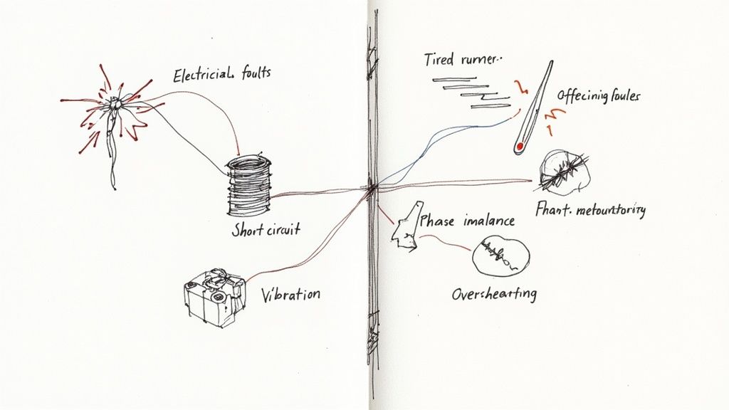
The Most Common Electrical Faults
Electrical issues are the usual suspects when a motor burns out. They go after the motor’s heart—the windings—either by slowly cooking them with heat or hitting them with a sudden, destructive jolt of energy.
Overloads: This is, without a doubt, the most common killer of motors. An overload happens when a motor is pushed to do more work than it was designed for. It draws too much current, gets hot, and stays hot. It’s like asking a weightlifter to hold a max lift indefinitely. Eventually, that sustained heat breaks down the winding insulation, and it’s game over.
Short Circuits: An overload is a slow burn, but a short circuit is an explosion. This is what happens when a low-resistance path is created where it shouldn't be, allowing a massive, uncontrolled amount of current to flow instantly. It's the electrical equivalent of a lightning strike, capable of melting windings and causing immediate, catastrophic failure.
Phase Imbalance or Loss: A three-phase motor needs a balanced diet of power across all three phases to run smoothly. When you lose a phase (single-phasing) or the voltages aren't equal (imbalance), it’s like trying to run an engine on two cylinders instead of three. The motor stumbles, vibrates, and draws way too much current through the remaining windings, leading to rapid overheating.
The Impact of Mechanical Stress
While we often focus on the electrical side, mechanical problems can be just as brutal. They introduce friction, vibration, and physical strain that will take down a motor just as surely as any electrical surge.
It’s easy to blame electricity for every motor failure, but that's a mistake. In reality, studies consistently show that mechanical problems—especially bearing failures—account for over 50% of all motor breakdowns. This is a huge number, and it proves that your protection strategy has to look at the whole picture, not just the wiring.
Key Mechanical Failure Points
Here are the mechanical culprits that are constantly trying to shorten your motor's life:
Bearing Failure: Bearings are the unsung heroes, letting the motor’s shaft spin freely. But when they get contaminated with dust and moisture, aren't lubricated properly, or have to deal with misalignment, they’re put under incredible strain. A failing bearing generates friction and heat, and that can quickly escalate to a seized motor.
Misalignment: When the motor shaft isn't perfectly lined up with the pump, fan, or gearbox it's driving, it creates intense, damaging vibrations. This constant rattling wears out bearings, couplings, and even the motor shaft itself. It's a guaranteed way to cause a premature failure.
Overheating from Poor Ventilation: Motors are designed to get warm, and they rely on cooling fans and clean vents to get rid of that heat. If those vents get clogged with sawdust, dirt, or grime, the motor can't breathe. Heat gets trapped, and the motor essentially cooks itself from the inside out, leading to the same end result as an electrical overload.
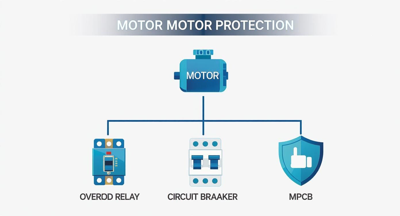
Your Arsenal of Motor Protection Devices
Now that we’ve covered the threats, let's look at the hardware that keeps your motors safe. Think of motor protection less like a single shield and more like a team of specialists. Each device has a specific job, and choosing the right one—or the right combination—is what creates a truly bulletproof system.
You wouldn't use a sledgehammer for a finishing nail, right? The same logic applies here. The device you need to stop a slow, grinding overload is completely different from the one that has to snap into action during a catastrophic short circuit.
Thermal Overload Relays: The Marathon Pacer
The old faithful of motor protection is the thermal overload relay. This is your motor's long-distance guardian, designed to protect it from the slow-burn damage of a sustained overcurrent. It’s smart enough to ignore the brief current spike a motor draws when it first kicks on.
Instead, it works with a bimetallic strip that gradually heats up and bends as excess current flows through it. If the overload drags on for too long, the strip bends far enough to trip a contact and shut down the motor—saving the winding insulation from getting cooked. It's a simple, tough, and affordable way to stop the #1 cause of motor failure in its tracks.
Fuses and Circuit Breakers: The Emergency Brakes
While an overload relay handles the slow stuff, fuses and circuit breakers are the emergency brakes. Their one and only job is to react instantly to the massive, destructive currents that come with a short circuit.
Fuses: These devices make the ultimate sacrifice. Inside a fuse is a small piece of metal engineered to vaporize in milliseconds when a huge overcurrent hits, breaking the circuit. They are incredibly fast, but they're a one-and-done solution and need to be replaced after they blow.
Circuit Breakers: A circuit breaker is essentially a heavy-duty, resettable switch. It uses a thermal trip for minor overloads and a magnetic trip for the big stuff, like short circuits. Once you've cleared the fault, you just flip the switch back on. This convenience makes them a go-to for many applications.
Motor Protection Circuit Breakers: The All-in-One Solution
A Motor Protection Circuit Breaker (MPCB) is exactly what it sounds like—a single, compact device that does the job of multiple components. It rolls adjustable thermal protection (like an overload relay) and instantaneous magnetic protection (like a circuit breaker) into one unit.
This integrated approach cleans up panel wiring, saves a ton of space, and gives you coordinated protection straight out of the box. MPCBs are purpose-built for the rigors of motor circuits, making them a very popular choice in modern industrial panels.
A critical piece of this puzzle is the motor starter, which handles the basic start/stop function. The global market for these components was valued at $7.8 billion in 2023 and is expected to climb to $12.8 billion by 2034. This growth underscores just how vital these integrated systems are. You can get more insights on this trend from custommarketinsights.com.
Motor Protection Relays: The Smart Coach
If the classic devices are individual players, think of a modern Motor Protection Relay (MPR) as the team's data-driven coach. These are smart, microprocessor-based units that go way beyond just watching for overcurrent.
An MPR is constantly monitoring a whole host of parameters, looking for signs of trouble like:
Phase loss or imbalance
Ground faults
Undercurrent (which could mean a broken belt or a pump running dry)
Too many starts in a short period
Over-temperature, often using sensors buried right in the motor windings
This level of detailed monitoring lets you diagnose problems before they turn into catastrophic failures, making them an incredibly powerful preventative tool.
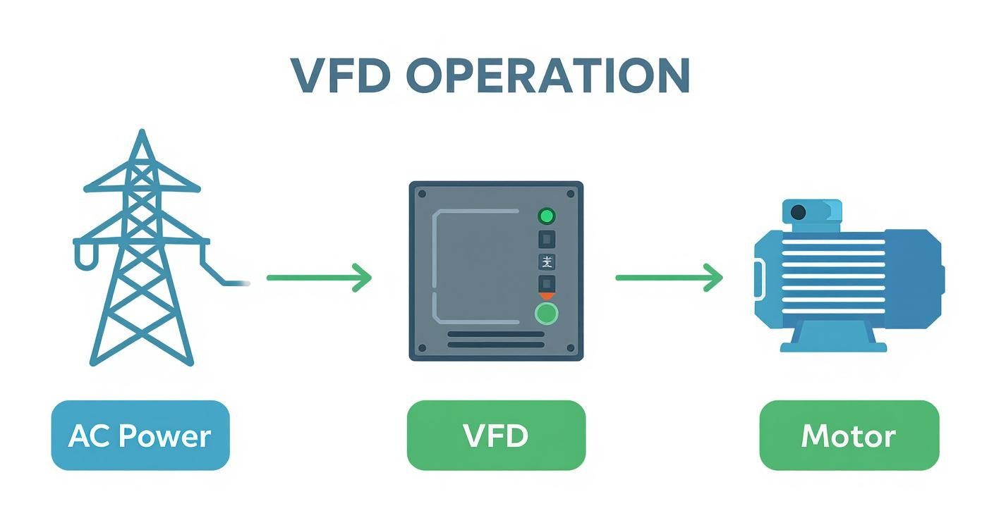
Variable Frequency Drives: The Advanced Controller
At its core, a Variable Frequency Drive (VFD) is a speed controller, but its onboard electronics give it some seriously impressive motor protection capabilities. Because a VFD is constantly managing the current, voltage, and frequency going to the motor, it can provide incredibly precise thermal overload protection.
VFDs also inherently protect against issues like phase loss, overvoltage, and undervoltage. You'll still need a fuse or breaker upstream for short-circuit protection, but a VFD can often take the place of a separate overload relay entirely. If you want a deeper dive, check out our guide on variable frequency drive basics. They're an amazing tool for both sophisticated control and comprehensive motor defense.
To help tie all this together, it's useful to see these devices compared side-by-side. Each has its place, and understanding their strengths and weaknesses is key to making the right choice for your application.
Comparison of Common Motor Protection Devices
Device Type
Primary Protection
Typical Application
Reset Method
Relative Cost
Thermal Overload Relay
Sustained Overcurrent
Paired with a contactor for basic motor starting circuits.
Manual or Automatic
Low
Fuse
Short Circuit (High Faults)
High-speed protection for sensitive equipment or high-fault current areas.
Replace
Very Low
Molded Case Circuit Breaker (MCCB)
Short Circuit & Overload
Main disconnects and branch circuit protection. General purpose.
Manual (Resettable)
Moderate
Motor Protection Circuit Breaker (MPCB)
Coordinated Overload & Short Circuit
All-in-one protection for individual motor circuits. Saves panel space.
Manual (Resettable)
Moderate to High
Motor Protection Relay (MPR)
Comprehensive (Current, Voltage, Phase, Temp)
Critical motors where advanced diagnostics and pre-emptive warnings are needed.
Manual, Automatic, or Remote
High
Variable Frequency Drive (VFD)
Advanced Overload, Phase Loss, Voltage Faults
Applications requiring speed control. Protection is a built-in benefit.
Programmable (Resettable)
Very High
As you can see, there's no single "best" device. The choice depends entirely on the motor's importance, the nature of the load, and your budget. For a simple fan, an overload relay and fuse might be perfect. For a mission-critical process pump, a smart MPR or a VFD is a much wiser investment.
How to Select and Coordinate Protective Devices
Knowing what the different protective devices are is only half the battle. The real skill is picking the right components and getting them to work together as a single, smart system. This all comes down to two key ideas: selection and coordination.
Think of it like putting together a championship football team. Selection is about getting the right player for each position—a tough lineman, a fast receiver. Coordination is teaching them to execute plays so the offensive line’s blocking gives the quarterback time to throw. You need both to win.
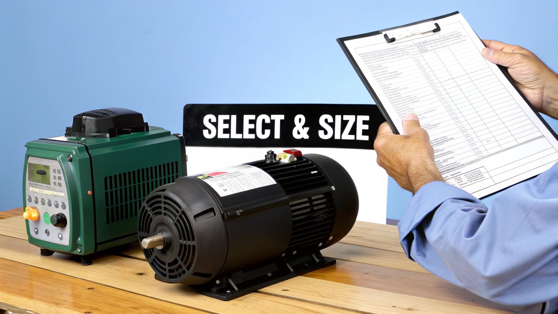
Selecting the Right Device for the Job
You always, always start with the motor's nameplate. That little metal tag is the motor’s birth certificate, and it has all the vital stats you need to choose the right protection. The most important number on there is the Full Load Amperage (FLA), which tells you exactly how much current the motor is designed to pull when it’s doing its job.
Here’s a straightforward way to select and set a basic overload relay:
Find the Motor FLA: First thing's first, get the Full Load Amperage right off the motor nameplate. This is your baseline.
Check the Service Factor (SF): Now, look for a Service Factor, which is usually 1.0 or 1.15. This number tells you how much of an overload the motor can handle for a short time without getting hurt.
Calculate the Trip Setting: According to standards like the National Electrical Code (NEC), if the SF is 1.15 or higher, you can set the overload trip up to 125% of the FLA. If the SF is 1.0 (or isn't listed), you stick to no more than 115% of the FLA.
For instance, say you have a 10 HP motor with an FLA of 28 amps and an SF of 1.15. You could set its overload relay as high as 35 amps (28 x 1.25). This gives the motor enough breathing room to handle temporary strains without annoying nuisance trips, while still protecting it from a truly damaging, sustained overload.
Sometimes, especially with complex loads, you also need to understand the relationship between power and rotational force. We have another guide that can help you with a torque calculation for motor applications if you need to dig deeper.
Coordinating Devices for Intelligent Protection
Coordination is where a truly great protection scheme shows its genius. It’s the art of making sure that only the device closest to a fault opens up, leaving the rest of your system running.
It’s like the fire sprinklers in an office building. If a fire starts in a single office, you want the sprinkler in that room to go off, not the main system that floods the entire building. The same logic applies here. A short circuit in one motor shouldn't trip the main breaker and plunge the whole plant into darkness.
Selective Coordination: The whole point is to create a hierarchy of protection. The "downstream" device (like the breaker protecting a single motor) should always react faster to a local problem than the "upstream" device (like the main panel breaker). This isolates the fault, minimizes downtime, and stops one small failure from causing a system-wide catastrophe.
To pull this off, engineers rely on Time-Current Curves (TCCs). These are graphs that show precisely how long a device will take to trip at any given current. By laying the TCC for the motor's breaker over the TCC for the main panel's breaker, you can see with your own eyes that they won't trip at the same time for the same fault.
This infographic gives you a simple look at this hierarchy in action.
As you can see, devices like overload relays and circuit breakers provide different layers of defense, all working to shield the most important asset: the motor. When you choose and set these devices correctly, you create a robust safety net that is both tough and smart.
Navigating Motor Protection Standards and Compliance
Getting motor protection right isn't just a matter of good engineering—it's a hard requirement, backed by strict safety standards. These codes aren't there to make life difficult; they exist to make sure every installation is safe, reliable, and insurable.
Think of them as a universal blueprint for safety. A motor installed in Texas should follow the same core safety principles as one running in Germany, and these standards make that possible.
The market reflects this focus on safety. Valued at $5.8 billion in 2024, the global motor protection market is expected to climb to $7.4 billion by 2030. That growth is being pushed by two things: more industrialization and tougher safety rules worldwide. You can dig into the numbers in this motor protection systems market report.
Key Standards to Know
When it comes to motor protection, two major players set the rules of the road globally:
NEC (National Electrical Code): In the United States, this is the bible for safe electrical design, installation, and inspection. Article 430 is the section you'll live in—it's dedicated entirely to motors, their circuits, and controllers.
IEC (International Electrotechnical Commission): This body creates the international standards used across Europe and much of the rest of the world for all things electrical.
While they might have slightly different ways of doing things, both the NEC and IEC are shooting for the exact same goals: safety and reliability.
Decoding NEC Article 430
If you're working in the U.S., you have to know NEC Article 430. It can look intimidating at first glance, but it's actually a logical roadmap that breaks down a motor circuit piece by piece. It tells you exactly what you need, from the power lines all the way to the motor shaft.
NEC Article 430 is the most cited article in the entire code for a reason. It provides a comprehensive framework covering everything from conductor sizing and disconnects to overload and short-circuit protection, leaving no room for guesswork in ensuring a safe installation.
Here are the non-negotiable parts Article 430 requires for any compliant motor circuit:
Disconnecting Means: You need a way to completely and safely kill power to the motor and controller for maintenance.
Short-Circuit and Ground-Fault Protection: This is your first line of defense against a catastrophic failure, usually a fuse or a circuit breaker.
Motor Controller: The device that actually starts and stops the motor, like a simple contactor or a modern VFD.
Motor Overload Protection: This is what saves the motor from burning itself out from overcurrents. An overload relay is the classic example.
Making sure your team is up to speed on these rules is crucial. Proper regulatory compliance training can make all the difference. Following these guidelines isn't just a box to check—it's a professional duty that keeps your systems effective, legally sound, and safe for everyone on the floor.
And in today's world of advanced controls, compliance also means managing electrical noise. Our guide on the harmonic filter for VFD is a great resource for tackling that side of things.
Practical Maintenance and Testing for Your Systems
Getting your motor protection system installed is a massive win, but it’s definitely not a "set it and forget it" deal. Think of your protective devices like smoke detectors in your home; you count on them to work in an emergency, but that trust is built on knowing they're actually working. A solid motor protection strategy absolutely has to include a proactive plan to make sure every component is ready to spring into action when you need it most.
If you let the system go, you're operating with a false sense of security. A device that fails to trip during a critical event can turn a totally preventable hiccup into a catastrophic failure. By locking in a routine maintenance schedule, you'll spot trouble early, get more life out of your motors, and ensure your protective gear performs exactly as it was designed to.
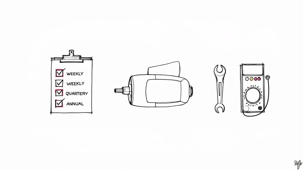
Your Actionable Maintenance Checklists
A structured game plan for maintenance is the best way to keep small tasks from being forgotten. Breaking it down into weekly, quarterly, and annual checks makes the whole process manageable and incredibly effective.
Weekly Visual Inspections:
Look for Hot Spots: Keep an eye out for any discoloration on terminals, wiring, or device casings. That's a classic sign of a bad connection or an overload condition.
Listen for Odd Noises: Pay attention to any weird buzzing or humming coming from contactors or breakers. That sound could be the first sign of a mechanical problem brewing.
Check Enclosure Integrity: Make sure all panel doors are latched tight. Vents should be clean and clear of any dust or debris—proper airflow is non-negotiable.
Quarterly Mechanical Checks:
Confirm Connection Torque: Grab a calibrated torque wrench and verify that every electrical connection on your breakers, relays, and terminals is tightened to the manufacturer’s spec. You'd be amazed how many failures start with a simple loose connection.
Inspect Device Housings: Get hands-on and physically check for any cracks, chips, or other signs of wear and tear on the protective devices themselves.
"A huge chunk of electrical faults can be traced back to simple mechanical issues like loose terminations. A quarterly torque check is one of the highest-impact, lowest-cost preventative tasks you can perform to keep your motor circuits reliable and safe."
Advanced Annual Functional Testing
Annual testing is where the rubber meets the road. It goes way beyond just looking and touching; this is about confirming your protective devices will actually do their job under fault conditions. You're here to validate trip settings and response times.
Thermography (Infrared Scanning):
One of the most powerful tools you can have in your predictive maintenance arsenal is thermography. An infrared camera can spot a hot, failing connection long before you could ever see it with your own eyes. Running regular thermal scans of your motor control panels will identify high-resistance points, helping you head off potential fires and unplanned downtime.
Injection Testing:
This is the ultimate functional test. It involves injecting a very precise current into a circuit breaker or overload relay to prove it trips at the right current level and within the specified time. Honestly, this is the only way to be 100% certain that your overload and short-circuit settings are dialed in correctly and that the device will protect your motor when a real fault happens. Building a proactive program on these checks is how you guarantee your systems are always ready to go.
Motor Protection Questions From the Field
Even when you have a solid plan, a few practical questions always pop up on the shop floor. Let's tackle some of the most common ones our engineers and technicians run into.
Fuses Versus Circuit Breakers: What's the Real Difference?
This one comes up all the time. People often wonder whether to use a fuse or a circuit breaker for motor protection, and while both protect against overcurrent, they couldn't be more different in how they work.
A fuse is a one-and-done, sacrificial device. When a major fault occurs, a small metal element inside melts, breaking the circuit permanently. It does its job, but you have to replace it every time.
A circuit breaker, on the other hand, is a reusable mechanical switch. It trips open when there's a problem but can be reset once you’ve cleared the fault. For motors, we typically lean on Motor Protection Circuit Breakers (MPCBs). They're built to handle a motor's initial inrush current without nuisance tripping, and their adjustable settings give you far more flexibility than a standard fuse.
How Do I Set an Overload Relay Correctly?
Setting an overload relay isn't guesswork—it's a critical step to keep a motor safe without causing unnecessary downtime. The whole process starts with a quick look at the motor’s nameplate for two key pieces of information: the Full Load Amperage (FLA) and the Service Factor (SF).
Here's the field-tested procedure:
Find the FLA: This is your baseline—the current the motor is designed to draw under a normal, full load.
Check the Service Factor: If the SF is 1.15 or higher, it means the motor can handle a bit more. You can set the overload trip point up to 125% of the FLA.
Stick to the Standard: If the SF is 1.0 or isn't listed, play it safe. The setting shouldn't go above 115% of the FLA.
This method gives the motor enough breathing room to handle slight load changes but ensures the relay will trip before any sustained overload can cook the windings.
Always double-check the manufacturer’s guides and local code requirements like the NEC. The sweet spot is always a balance between reliable operation and bulletproof protection.
Can a VFD Just Replace the Starter and Overload Relay?
For most modern setups, the answer is a definite yes. A Variable Frequency Drive (VFD) is packed with smart electronics that provide fantastic motor protection right out of the box.
VFDs offer incredibly sophisticated overload protection—often using a precise thermal model of the motor—and they also guard against things like phase loss, overvoltage, and undervoltage.
But here’s the crucial part: a VFD is not a substitute for short-circuit protection. You absolutely still need fuses or a circuit breaker installed on the line side of the drive. This is non-negotiable for protecting the VFD's sensitive internal components (and the rest of your system) from a catastrophic fault. Always dig into the VFD's installation manual to see what it requires for upstream protection.
At E & I Sales, we live and breathe this stuff. We specialize in designing and building the custom UL control panels and integrated systems that turn motor protection theory into a reliable reality. From picking the right components to commissioning a fully coordinated system, our team ensures your most critical assets are safe and ready to run.
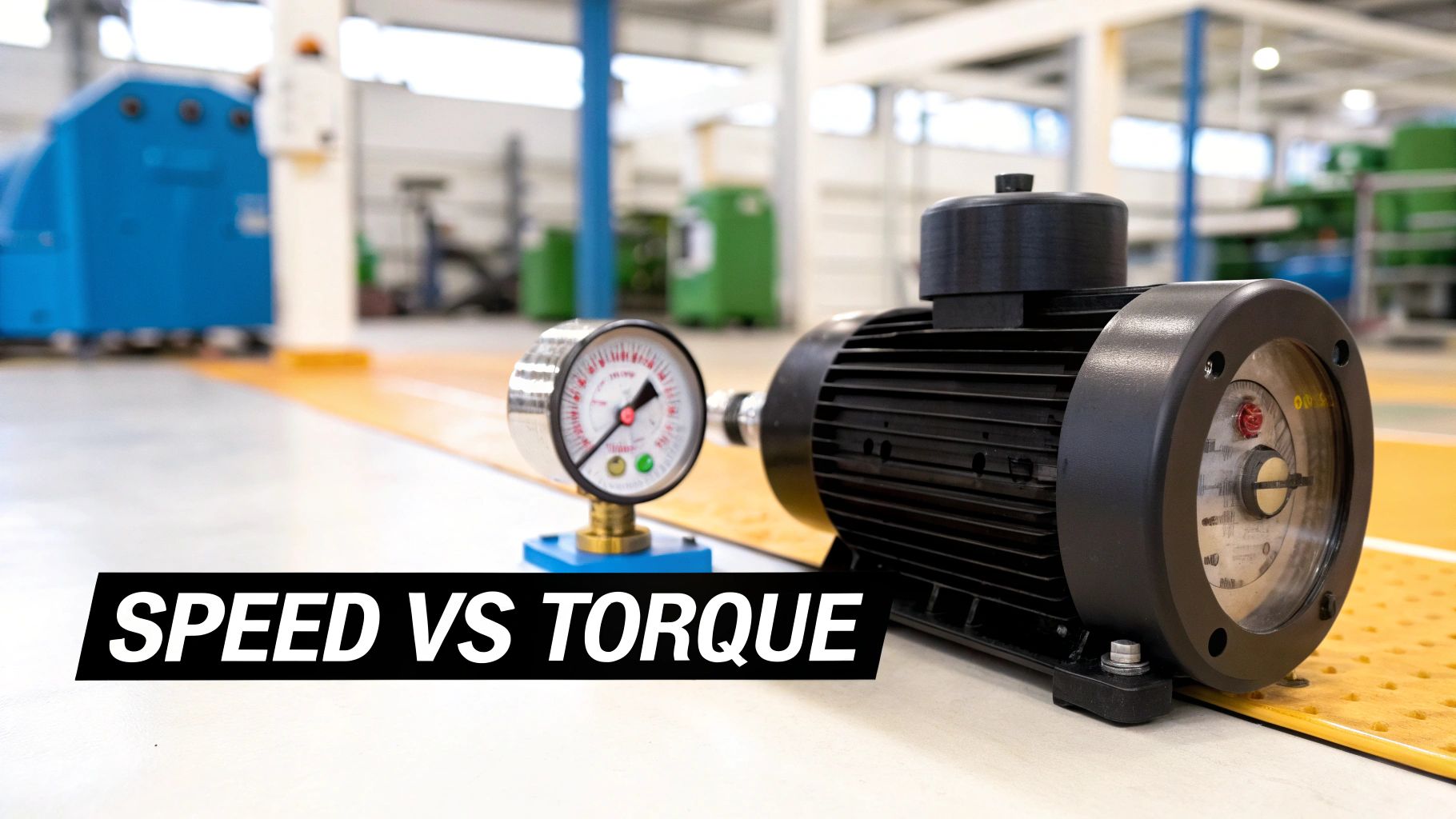
Calculating motor torque is the first, and arguably most important, step in sizing a motor for any job. It all comes down to the relationship between a motor's power (horsepower or kilowatts), its rotational speed (RPM), and the twisting force it can actually produce. A solid torque calculation is your best insurance against picking a motor that can't start, run, and stop a load properly, saving you from premature failures and overheating headaches.
Why Getting Torque Right is Non-Negotiable
Nailing the torque calculation is the bedrock of any reliable mechanical system. We're not just trying to make something move; we're trying to make it move correctly, efficiently, and safely for years to come. Get this wrong, and you're setting yourself up for a domino effect of expensive and potentially dangerous problems down the line.
I always tell people to think of it like picking an engine for a truck. You wouldn't put a four-cylinder sedan engine in a semi-trailer and expect it to haul a full load. It would constantly struggle, redline, and burn out in no time. The reverse is also true—putting a massive diesel engine in a compact car is a colossal waste of money, space, and fuel. The exact same logic applies to industrial motors.
The Real-World Consequences of a Bad Calculation
When you misjudge the torque, the fallout is swift and significant. Undersizing a motor is a classic mistake that leads to constant stalling, overheating, and a drastically shortened service life as the motor strains against a load it was never meant to handle.
On the other hand, oversizing might seem like the "safe" option, but it creates its own set of problems:
Wasted Energy: An oversized motor runs well below its peak efficiency, which means you're paying for electricity that's just getting turned into waste heat.
Increased Wear and Tear: The powerful starting torque of a bigger-than-needed motor can slam gearboxes, couplings, and other machinery, causing premature wear.
Higher Upfront Costs: It’s simple—bigger motors and the beefier controls they require cost more. That’s money straight out of your project budget for no tangible benefit.
Not All Torque is Created Equal
To do a proper torque calculation for a motor, you have to recognize that a motor's job changes from one second to the next. The demands aren't constant, so you need to account for the different phases of its work cycle.
Pro Tip: Look at the entire duty cycle, not just the continuous running phase. I've seen countless motors fail because the engineer only calculated for steady-state operation and completely ignored the massive peak torque needed to get the load moving from a dead stop.
You really need to get familiar with three specific types of torque:
Starting Torque: You might hear this called "locked-rotor torque." It's the brute force the motor can generate from a standstill. This number has to be high enough to overcome inertia and static friction to get things going.
Full-Load Torque: This is the workhorse spec—the continuous torque the motor can deliver at its rated speed without breaking a sweat (or overheating). It’s what you’ll be looking at for normal, day-in-day-out operation.
Breakdown Torque: Sometimes called "pull-out torque," this is the absolute maximum a motor can dish out for a brief moment before it stalls and the speed plummets. It’s a great indicator of how well the motor can handle a sudden, temporary overload.
Once you have a handle on these distinctions, your calculations will start to reflect the true demands of your system, leading to a much more reliable design.
The Core Formulas for Motor Torque
At the end of the day, every motor selection comes down to a handful of essential equations. This is where we stop talking theory and start getting practical, turning a motor’s power and speed ratings into the actual twisting force it can deliver. Getting these formulas right is non-negotiable for sizing a motor that won't let you down.
The main relationship connects torque directly to power and rotational speed. A classic mistake, however, is mixing up your units. A formula built for kilowatts and RPM will give you a useless number if you plug in horsepower. Let's break down the formulas for both Metric and Imperial systems to make sure that never happens.
Calculating Torque from Power and Speed
This is your go-to method for figuring out a motor's full-load torque. You’ll find the power and speed right on the motor's nameplate, making this calculation as straightforward as it gets.
The Metric Formula (Nm)
If you're working in metric, you're using kilowatts (kW) for power and revolutions per minute (RPM) for speed. The result is torque in Newton-meters (Nm), the standard in the SI system.
Here’s the formula: Torque (Nm) = Power (kW) × 9550 / Speed (RPM)
That magic number, 9550, is a constant that does all the heavy lifting on unit conversions (from kW to watts, and RPM to radians per second). It's a massive shortcut that saves you from having to do that tedious math every single time.
A Lesson from the Field: I once troubleshot a conveyor system that kept stalling. The initial math seemed correct, but the engineer had accidentally used the metric power value (kW) with an imperial formula constant. It was a tiny slip-up, but it resulted in a motor that was nearly 30% underpowered for the application.
The Imperial Formula (lb-ft)
For those of us working with Imperial units, the inputs are horsepower (hp) and speed in RPM. Your torque output will be in pound-feet (lb-ft), which is common across North American industrial equipment.
The formula looks like this: Torque (lb-ft) = Power (hp) × 5252 / Speed (RPM)
Just like its metric counterpart, the constant 5252 is the key. It neatly reconciles the different units of horsepower, RPM, and pound-feet so the math just works. For a deeper dive into motor sizing, you can find some great information from industry suppliers like E & I Sales.
Common Torque Calculation Formulas and Unit Conversions
To make things even easier, here’s a quick-reference table. It's a good idea to keep this handy to avoid any mix-ups between unit systems.
Torque Unit
Power Unit
Speed Unit
Formula
Newton-meter (Nm)
Kilowatt (kW)
RPM
Torque = (Power × 9550) / Speed
Pound-foot (lb-ft)
Horsepower (hp)
RPM
Torque = (Power × 5252) / Speed
Ounce-inch (oz-in)
Horsepower (hp)
RPM
Torque = (Power × 1,008,384) / Speed
This table covers the most common scenarios you'll encounter, from small-scale robotics to heavy industrial machinery.
An Alternative: Calculating Torque from Current
While the power-and-speed formula is the gold standard for AC induction motors, there's another important relationship to know, especially if you work with DC motors. For brushed and brushless DC (BLDC) motors, torque is almost perfectly proportional to the current it draws.
This relationship is all about the motor's torque constant, or Kt.
For DC Motors: This connection is beautifully linear. More current means more torque. Simple.
For AC Motors: Be careful here. This method is much less reliable for AC motors because their torque is also affected by voltage and power factor, both of which change with the load. Using current alone for an AC motor will only give you a rough ballpark figure.
The formula itself couldn't be simpler: Torque (Nm) = Current (A) × Kt
The Kt value is the torque constant, usually given in Newton-meters per Amp (Nm/A) right in the motor's datasheet. This formula is a game-changer when you're using a motor controller that regulates current, because it means you can directly control the motor's torque output.
For instance, if a BLDC motor has a Kt of 0.08 Nm/A and you're pushing 10 Amps through it, you can confidently expect it to produce about 0.8 Nm of torque. This direct link is fundamental for precision applications like robotics and CNC machines, but remember to stick with the power-based formula for your standard AC induction motors to get an accurate, reliable result.
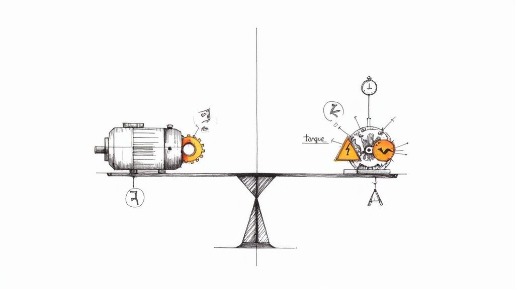
Getting Your Hands Dirty: Applying Torque Formulas in the Real World
Theory is one thing, but applying these formulas to messy, real-world machinery is where the rubber really meets the road. The equations give you a starting point, but correctly sizing a motor for an industrial application means digging into the specifics of load types, system friction, and the unique demands of the job.
Let's look at a few common scenarios I’ve run into over the years.
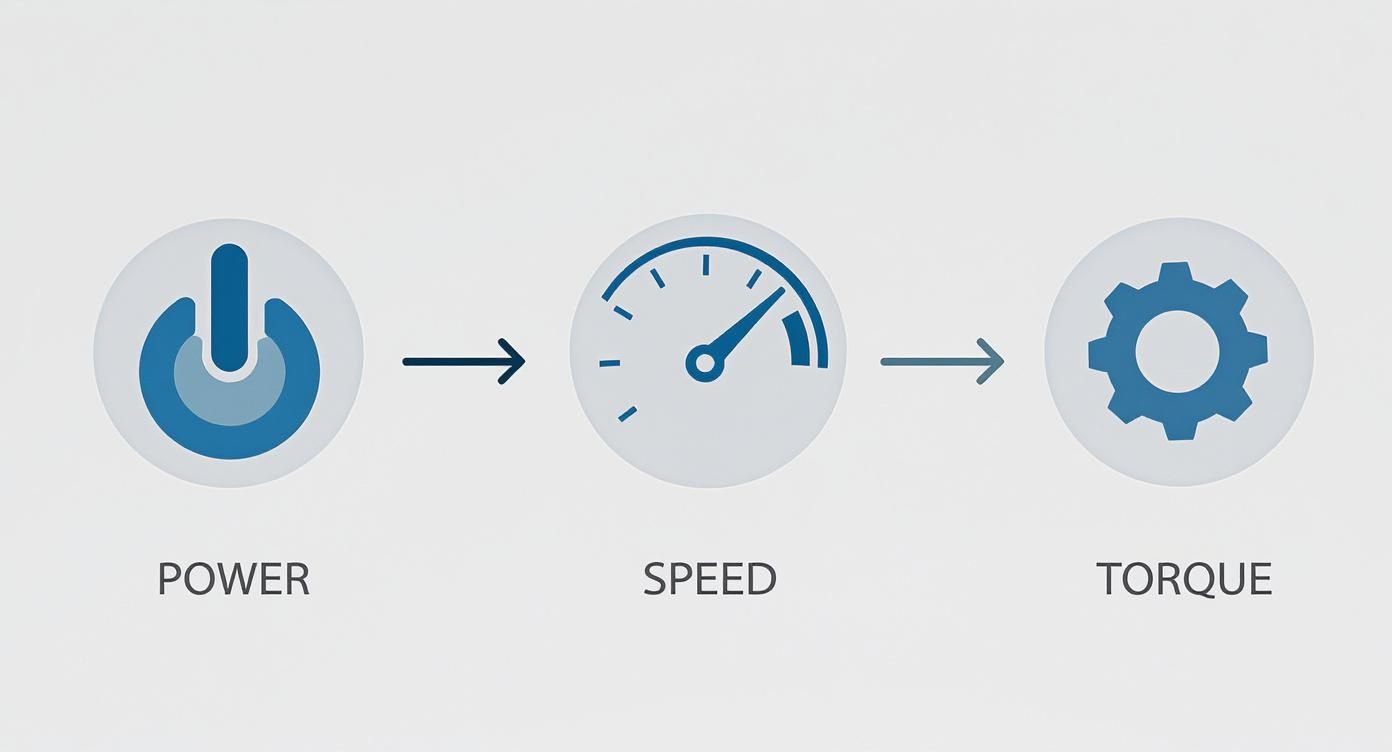
This visual really boils it down to the core relationship we're working with: power and speed are your inputs, and torque is the result.
It’s a simple but powerful concept. Everything we do in motor sizing comes back to balancing these three variables to get the performance you need.
Sizing a Motor for a Conveyor Belt
Conveyors are the workhorses of manufacturing and logistics. They're a perfect example of turning a motor's rotation into straight-line motion. The big puzzle here is figuring out how much force it takes to move everything on that belt and overcome all the friction, then translating that back into the rotational torque the motor needs to supply.
Let's say you've got a horizontal conveyor that needs to move 200 kg of product at a steady 0.5 m/s. The drive pulley has a radius of 0.15 meters, and we'll estimate the system's coefficient of friction at 0.05.
First, we need the force required to beat friction.
Friction Force = Total Mass × g × Coefficient of Friction
Friction Force = 200 kg × 9.81 m/s² × 0.05 = 98.1 Newtons (N)
That’s the constant pull needed from the belt. Now, let’s see what that means for the motor's drive pulley.
Torque (Nm) = Force (N) × Radius (m)
Torque (Nm) = 98.1 N × 0.15 m = 14.72 Nm
So, 14.72 Nm is our baseline torque just to keep the fully loaded belt rolling. But that's in a perfect world, and industrial equipment is anything but.
Don't Forget System Inefficiencies
Every mechanical system has losses. Nothing is 100% efficient. You lose a little bit of energy in the gearbox, in the bearings, and even from the belt stretching. I usually start by assuming an efficiency of about 85% for a standard gearbox and belt drive. It's a safe, real-world number.
To get the actual torque the motor needs to deliver, you have to account for these losses.
Required Motor Torque = Load Torque / System Efficiency
There's our number. The motor you choose must be able to comfortably provide 17.32 Nm of continuous torque. If you want to dive deeper into this part of the process, our collection of articles on motor sizing techniques is a great resource.
Calculating Torque for a Centrifugal Pump
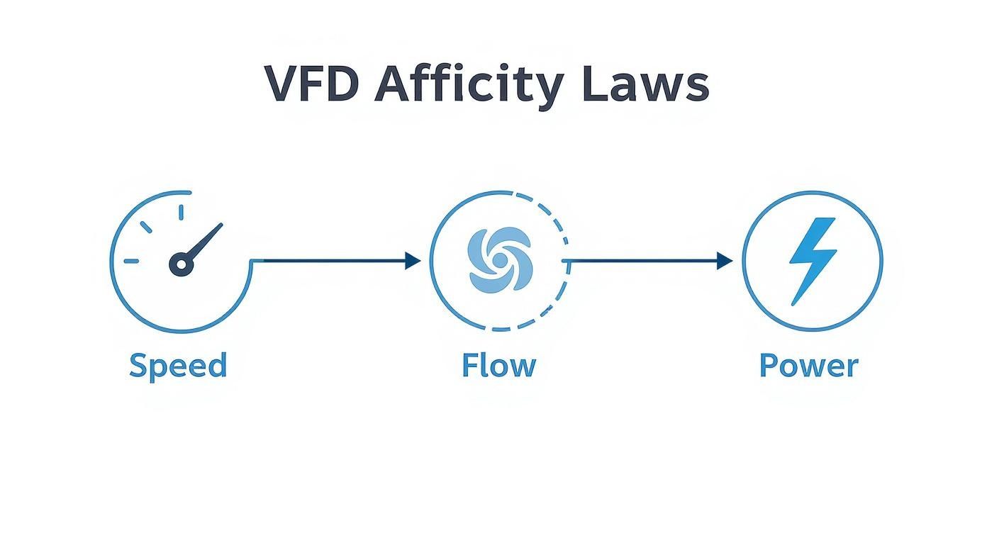
Pumps are a whole different animal. Unlike a conveyor with its relatively steady load, a centrifugal pump's torque requirement is deeply tied to its speed. The faster it spins, the exponentially harder the motor has to work. We call this a "variable torque" load.
Imagine we're selecting a motor for a pump that needs 15 kW of power at its target speed of 1750 RPM. Here, the calculation is refreshingly straightforward.
Let's plug it into the metric formula:
Torque (Nm) = Power (kW) × 9550 / Speed (RPM)
Torque (Nm) = 15 kW × 9550 / 1750 RPM = 81.86 Nm
Simple as that. The motor we spec for this job must be able to deliver at least 81.86 Nm continuously at 1750 RPM.
Expert Insight: With pumps and fans, the starting torque is usually quite low. The real challenge is making sure the motor has enough guts to handle the load as it ramps up to full speed. I always make it a point to check the motor's speed-torque curve to ensure it can deliver sufficient torque through the entire acceleration phase, not just at the final operating speed.
Determining Torque for a Robotic Arm
Robotics applications are where torque calculations get really interesting because the loads are constantly changing. The required torque shifts with every move, depending on the arm's position, the weight it's lifting, and how fast it needs to accelerate. Your job is to find the peak torque required for the absolute worst-case scenario.
Picture a single joint on a robotic arm holding a 5 kg payload at the end of a 0.8-meter arm segment, stretched out horizontally. The motor has to hold not just the payload, but also the weight of the arm itself—we'll say that's 10 kg, with its center of mass 0.4 meters from the joint.
The total holding torque is a sum of the two forces.
Torque_payload = 5 kg × 9.81 m/s² × 0.8 m = 39.24 Nm
And remember, that's just the torque needed to hold the arm steady. To get it moving, you need even more. In electric motors, torque is directly proportional to the supply voltage; more voltage equals more torque. For instance, an electric vehicle motor running on 400V might produce 266 Nm. When that's run through a gear ratio of 7.05, the final torque at the wheels becomes a massive 1,875.3 Nm. This interplay between voltage, gearing, and torque is fundamental to modern machine design.
How to Measure Torque and Verify Your Numbers
After you've run the formulas, you've got a solid theoretical number for your motor's required torque. But in the real world of engineering, theory is only half the battle. The crucial next step is to bridge the gap between your calculations and physical reality, making sure your numbers hold up when the rubber meets the road. This is where measurement comes in, giving you the hard data you need for quality control, performance tuning, and troubleshooting.
Calculations can only get you so far. They don't always account for tricky variables like inconsistencies in materials, minor flaws in assembly, or unexpected friction points in the system. Physical measurement is your ground truth—it confirms that the motor you've picked, or the machine you've built, actually performs the way you designed it to.
The Right Tools for Torque Measurement
To directly measure the twisting force of a motor, you need specialized instruments. The two workhorses for this job are dynamometers and dedicated torque sensors, and each has a specific role to play.
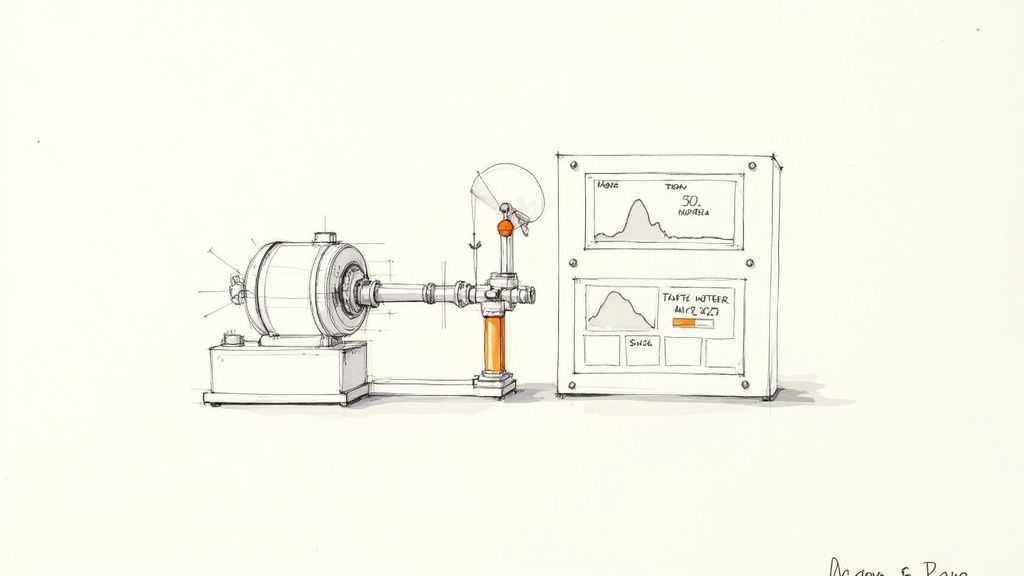
Dynamometers: Often just called a "dyno," this is a complete testing system. It doesn't just measure torque; it also measures speed, which allows you to map out the motor's full power output across its entire operating range. A dyno applies a controlled load to the motor, making it the perfect tool for creating detailed performance curves.
Torque Sensors: These are more focused tools designed to measure torque directly. You can install them inline between the motor and the load in a real application, giving you a live feed of how much torque is actually being demanded during a machine's cycle.
When it comes time to check your calculated torque numbers, these physical measurement tools are absolutely essential. To get a better feel for the equipment, it's worth understanding how a dynamometer works and the principles behind it.
How Modern Torque Sensors Work
Most modern torque sensors are built on a brilliantly simple concept: the strain gauge. This technology is the bedrock of industrial measurement. Back in 1938, Professor A.C. Ruge developed the first one, and by 1952, the foil strain gauges we still use today became the standard. Modern sensors based on this principle can achieve impressive accuracies, often within 0.1% to 0.5% of their full scale.
So how does it work? A strain gauge is basically a flexible resistor that's bonded directly to the motor's shaft. When torque is applied, the shaft twists ever so slightly, which stretches or compresses the gauge. This tiny physical change alters its electrical resistance. That change can be measured with incredible precision and converted into a torque value.
There are two main flavors of torque sensors built on this principle:
Reaction Torque Sensors: These are for measuring stationary torque. They're perfect for jobs like checking the tightening torque on a bolt or measuring the force needed to hold a robotic arm in a fixed position.
Rotary Torque Sensors: As the name implies, these are designed to measure torque on a spinning shaft. They use slip rings or wireless telemetry to send the signal from the rotating sensor to a stationary receiver, making them indispensable for testing motors while they're running.
Setting Up a Practical Test Rig
You don't always need a million-dollar lab to verify your torque calculations. A well-designed test rig can get you the data you need without breaking the bank.
A Tip from the Trenches: Always start with a rigid, securely mounted base. I've seen countless tests ruined because the motor or sensor was mounted on a flimsy workbench. Any vibration or flexing in your setup will introduce noise and errors into your measurements, making them worthless.
Here's a straightforward approach to building a reliable test rig:
Mount the Motor Securely: Bolt the motor down to a heavy, stable plate. Make sure it absolutely cannot move or vibrate, even under maximum load.
Couple the Sensor: Connect your rotary torque sensor to the motor shaft with a high-quality, zero-backlash coupling. Misalignment is the enemy of accurate measurement, so take your time here.
Apply a Load: Connect the other end of the sensor to a load. For smaller motors, a simple friction brake might do the trick. For larger systems, you'll want a more sophisticated dynamometer or braking system.
Collect the Data: Use a data acquisition (DAQ) system to record the output from the torque sensor and a tachometer to log the speed simultaneously.
With this setup, you can run the motor through its expected operating conditions and see how the real-world torque lines up with your calculations. If the numbers match, you can move forward with confidence. If they don't, you now have the data you need to figure out what's wrong—whether it's an unexpected source of friction or an issue with one of the many https://eandisales.com/products/electric-motors/ available.
Advanced Considerations for Motor Selection
Getting the basic torque calculation right is a great start, but experienced engineers know that's just the baseline. The real-world isn't a clean, predictable lab environment. To design a machine that lasts, you have to account for the unexpected stresses and strains of daily operation. This is where you move from a good motor selection to a great one.
A critical piece of this puzzle is the service factor. Think of it as an engineering safety net—a multiplier you apply to your calculated torque to build in a buffer for the harsh realities of an industrial setting. It’s what ensures your system doesn't just work on paper but survives in the field.
For instance, a motor driving a fan with a smooth, continuous load might get by with a service factor of 1.0 or 1.1. But if that motor is powering a rock crusher, which gets hammered with shock loads all day, you'll need a service factor of 1.5 or more to prevent a premature burnout.
Applying Service Factors Correctly
Picking the right service factor is part art, part science. It demands a hard look at the actual conditions the motor will face. You have to think about what's going to stress the motor and drivetrain beyond the simple, calculated load.
Load Type: Is the load steady, or does it hit hard? Things like reciprocating compressors or punch presses are brutal on motors and demand a higher service factor.
Duty Cycle: How often are you starting and stopping? Any application with more than 10 starts per hour puts a lot of thermal stress on the windings from the repeated inrush current, warranting a higher factor.
Operating Environment: High ambient temperatures, a ton of dust, or high altitudes all hinder a motor's ability to cool itself. This effectively lowers its performance and means you need to build in a bigger safety margin.
I once saw a conveyor system that kept failing. The engineer had calculated the basic running torque perfectly but completely missed the fact that it was in a dusty warehouse and was started and stopped constantly. A simple 1.25 service factor would have pointed to a tougher motor and saved the company months of downtime.
For complex machinery with constantly changing loads, like robotics or CNC machines, a single torque number just won’t cut it. This is where you need to go beyond static calculations and use modern computational models. These tools let you simulate the motor’s performance through its entire work cycle, not just at one peak moment.
This approach gives you a much clearer picture of the torque calculation for a motor, especially with variable loads. For example, you can model how adjusting the frequency in an AC motor setup will affect its performance under different conditions. Our guide on AC motor variable speed dives deeper into this topic.
The accuracy you can get with these methods is impressive. Research models that account for things like time delays and other non-linear variables have shown torque estimation accuracies above 95%. This level of precision is exactly what's needed to design the highly efficient and responsive automated systems we rely on today.
By embracing these advanced steps—applying the right service factors and using dynamic modeling for complex loads—you stop just picking a motor and start engineering a truly resilient machine.
Frequently Asked Questions About Motor Torque
Even when you've got the formulas down, some practical questions always seem to surface during the motor selection process. That's completely normal—the real world rarely fits perfectly into a neat equation. Let's walk through a few of the most common hurdles to clear up any confusion so you can choose your next motor with total confidence.
Starting Torque vs. Full-Load Torque
People often mix these two up, but they describe two totally different, and equally critical, phases of motor operation.
Starting torque, which you might also hear called locked-rotor torque, is the raw, brute force a motor can generate from a complete standstill (0 RPM). This is the initial muscle needed to overcome the system's inertia and static friction just to get things moving.
Full-load torque, on the other hand, is the steady, continuous twisting force the motor provides when it's humming along at its rated speed and power. This is the "workhorse" spec that tells you if the motor can handle the job long-term without overheating or giving up.
Here's a classic mistake I see all the time: choosing a motor with enough full-load torque but not nearly enough starting torque. The motor might be perfectly capable of running the load once it's up to speed, but it will never actually get it started. You have to check both specs against what your system demands.
How a Gearbox Changes Everything
A gearbox is a game-changer in mechanical design, and it completely alters your torque calculations. Think of it as a torque multiplier—it trades speed for more force. The gear ratio is the key.
For instance, a gearbox with a 10:1 ratio cuts the output speed to just one-tenth of the motor's speed. But in return, it boosts the available torque by a factor of 10, minus a little bit lost to friction inside the gearbox itself (efficiency losses are usually between 5-15%).
So, when a gearbox is in the picture, you have to work your torque calculation for the motor in reverse:
First, figure out the final torque you need at the load itself.
Next, divide that load torque by the gear ratio.
Finally, account for the efficiency loss by dividing that result by the gearbox's efficiency rating (e.g., divide by 0.90 if it's 90% efficient).
The number you're left with is the actual torque the motor needs to produce.
Can I Figure Out AC Motor Torque From Current?
I get this question a lot, and the answer is a hard "it's complicated." With a DC motor, torque and current have a nice, direct, linear relationship defined by its Kt (torque constant). But that's just not the case for AC induction motors.
An AC motor's torque is the result of a complex dance between current, voltage, efficiency, and—the real kicker—the power factor. The power factor isn't a fixed value; it changes dynamically as the motor's load changes.
Because of this, just clamping an ammeter on an AC motor won't give you an accurate torque reading. For reliable and precise results, you really need to stick to the proven formulas that use power (kW or hp) and speed (RPM). It's better to think of amperage on an AC motor as a health indicator or a rough gauge of its workload, not as a direct input for calculating exact torque.
At E & I Sales, we live and breathe this stuff. We specialize in helping engineers and system integrators select the right motor and control solutions for tough industrial jobs. Our experts can walk you through everything from the first calculation to the final commissioning. Discover how our deep product knowledge and system integration services can make your next project a success at https://eandisales.com.
A harmonic filter for VFD applications is a piece of hardware that cleans up the electrical “noise” that Variable Frequency Drives inevitably create. Think of it as noise-canceling headphones for your entire power system, making sure sensitive equipment runs smoothly and preventing damage from these electrical disturbances.
Why VFDs Pollute Your Power (and How Filters Clean It Up)
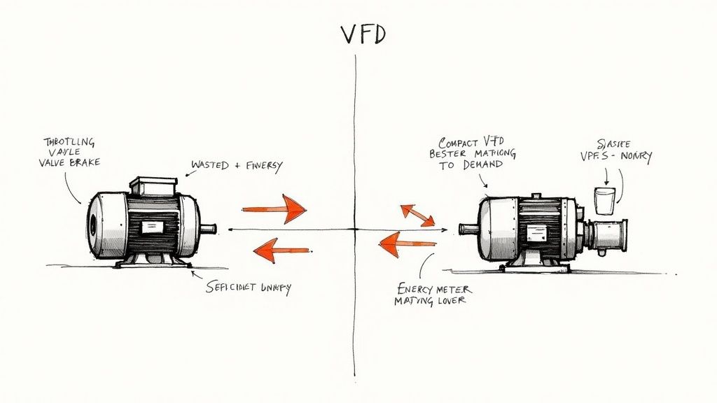
Variable Frequency Drives (VFDs) are the heroes of industrial efficiency. They give engineers incredibly precise control over motor speeds, saving a ton of energy and fine-tuning processes. But this control comes with a side effect: electrical pollution, officially known as harmonic distortion.
To get a picture of what's happening, imagine your facility's power is a perfectly smooth, clean river flowing from the utility.
A VFD does its job by taking this clean alternating current (AC), chopping it up into direct current (DC), and then rapidly switching it back into a simulated AC waveform to control the motor. This constant, high-speed switching is like dropping a bunch of disruptive dams and turbines into your once-pristine river. The flow becomes choppy, chaotic, and full of turbulent waves.
These electrical "waves" are harmonics.
Harmonics: More Than Just a Nuisance
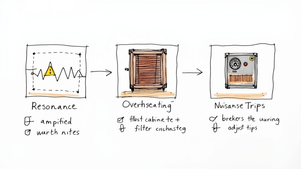
This harmonic distortion isn't just a minor issue; it's a real threat to your plant's stability and reliability. When this "dirty power" starts circulating through your electrical network, it triggers a whole host of problems that are often tricky to diagnose.
Equipment Overheating: Harmonics force extra current through transformers, wiring, and motors. This generates excess heat that can cook components from the inside out, leading to premature failure.
Nuisance Tripping: Sensitive electronics, like circuit breakers and even other VFDs, can misinterpret this distortion as a genuine fault. The result? Unexpected shutdowns and expensive downtime.
Data Corruption: Your PLCs, computers, and other digital controllers rely on clean power. When the supply is distorted, you can see unexplained errors and corrupted data.
Reduced Equipment Lifespan: The constant stress from harmonic currents significantly shortens the operational life of just about everything connected to the system.
Measuring the Mess with Total Harmonic Distortion (THD)
To put a number on this electrical chaos, we use a metric called Total Harmonic Distortion (THD). It’s a straightforward measurement that compares the distorted waveform in your system to a pure, clean sine wave. High THD levels are a red flag, telling you that your system is suffering from serious harmonic pollution.
This is where a harmonic filter for VFD systems becomes absolutely essential. It’s specifically engineered to smooth out those chaotic waves right at the source—the drive itself. By filtering out these damaging harmonics, it protects every single piece of equipment downstream. You can get a refresher on how these drives work in our guide to VFD basics.
The operational impact of installing a filter is immediate and significant.
Operational Impact With vs Without a Harmonic Filter
The table below breaks down the real-world differences you can expect to see in your system's performance.
System Characteristic
VFD Without Harmonic Filter
VFD With Harmonic Filter
Power Quality
Poor; high Total Harmonic Distortion (THD)
Excellent; low THD (typically <5%)
Equipment Temperature
Transformers, motors, and cables run hotter
Components operate at normal, cooler temperatures
System Reliability
Prone to nuisance tripping and unexpected shutdowns
Stable and reliable with minimized downtime
Energy Efficiency
Lower; energy is wasted as heat (I²R losses)
Higher; system runs more efficiently without waste
Component Lifespan
Reduced due to thermal and electrical stress
Extended operational life for all connected gear
Compliance
Likely fails to meet IEEE 519 standards
Meets or exceeds IEEE 519 and other utility standards
As you can see, the choice is pretty clear. Leaving harmonics unchecked puts your entire operation at risk, while adding a filter is a direct investment in stability and longevity.
With VFDs being so common in industrial and commercial settings—often in robust three-phase power installations—dealing with harmonics is no longer an option. It's a necessity. The global market for these filters is growing fast as more industries prioritize power quality. Installing a filter isn't just an upgrade; it’s a foundational step for building a reliable, modern facility.
Exploring Different Types of Harmonic Filters
Picking the right harmonic filter for a VFD isn't a one-size-fits-all deal. Different problems on the factory floor call for different tools, and the world of harmonic mitigation really boils down to three core technologies: Passive, Active, and Hybrid filters.
Each one takes a unique swing at cleaning up your power, and each has its own strengths and sweet spots. Getting a handle on how they work is the first step to choosing a solution that actually fits your plant's needs, budget, and performance targets. Let's break them down.
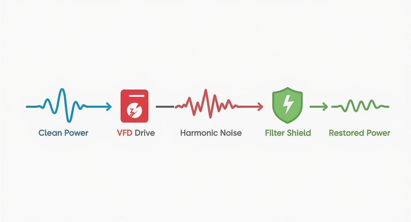
The infographic below gives a great visual of this process. It shows the journey of clean power from the utility, how it gets "dirtied" by the VFD, and then how a filter steps in to clean it back up.
You can see how the filter acts like a bouncer, stopping that jagged harmonic noise and only letting the smooth, clean sine wave through to the rest of your equipment.
Passive Harmonic Filters: The Rugged Workhorse
Passive filters are the old guard, the original, time-tested solution for taming harmonic distortion. Think of them like a big acoustic panel in a recording studio, specifically built to absorb one predictable, annoying sound frequency. They’re built from a simple, tough combination of inductors (reactors) and capacitors.
This circuit is precisely "tuned" to target a specific harmonic frequency. Most often, that's the 5th harmonic, which is the biggest troublemaker created by common six-pulse VFDs.
When the distorted current from the drive hits the filter, this tuned circuit creates an easy, low-resistance path. It essentially traps and soaks up those specific harmonic frequencies, stopping them from polluting your entire electrical system.
Key Takeaway: A passive filter is a fixed solution. It's engineered to solve a known, consistent harmonic problem, making it a fantastic and cost-effective choice for dedicated loads where the harmonic profile stays pretty much the same day in and day out.
Their simple, bulletproof design—no fancy electronics—makes passive filters incredibly reliable. They require almost no maintenance, making them a true "set it and forget it" solution in the right application.
Active Harmonic Filters: The Smart Solution
If a passive filter is an acoustic panel, then an active harmonic filter (AHF) is a pair of high-tech, noise-canceling headphones. It doesn't just block a fixed frequency; it actively listens to the noise and creates an exact opposite sound wave to wipe it out.
An AHF uses precise sensors to constantly monitor the current on your electrical line. Its brain—an internal processor—analyzes the harmonic distortion in real-time and instantly injects a corrective, opposing current back into the system.
This "anti-harmonic" current perfectly cancels out the unwanted distortion, leaving you with a pristine sine wave.
Dynamic Correction: They adapt on the fly as loads and the harmonic mix change.
Broad Spectrum: They can kill multiple harmonic orders at once (like the 5th, 7th, 11th, and beyond).
Multi-Functional: Many can also fix other power quality headaches, like poor power factor and load imbalances.
This smart, adaptive capability makes an active harmonic filter for VFD systems the go-to for facilities with a bunch of non-linear loads, fluctuating production cycles, or super-strict power quality demands, like what you’d find in a data center or hospital.
Comparing Harmonic Filter Technologies
To make the choice clearer, let's put these technologies side-by-side. Each has a distinct role, and seeing their pros and cons laid out can help pinpoint the best fit for your specific challenge.
Filter Type
Correction Method
Best For
Pros
Cons
Passive
Uses inductors and capacitors to create a low-impedance path that "traps" specific harmonic frequencies.
Single, consistent loads where the harmonic profile is predictable (e.g., dedicated pumps, fans).
– Very reliable and robust – Lower initial cost – No complex electronics – Minimal maintenance
– Fixed correction for specific harmonics – Can create resonance issues if not sized correctly – Less effective on changing loads – Can be bulky
Active
Injects an opposing, corrective current to actively cancel out a broad spectrum of harmonic distortion.
Facilities with multiple, varied, or dynamic non-linear loads (e.g., machining centers, hospitals).
– Adapts to changing loads in real-time – Corrects a wide range of harmonics – Can also improve power factor – Highly precise
– Higher initial cost – More complex, with active electronics – Requires more skilled commissioning
Hybrid
Combines a passive filter for the main harmonic (e.g., 5th) with a smaller active filter for the rest.
Large industrial applications needing high performance without the full cost of a purely active solution.
– High performance at a better price point – Efficiently handles heavy distortion – Balances cost and capability
– More complex than a standalone passive filter – Integration of two technologies requires careful design
Ultimately, this table shows there's no single "best" filter—only the best filter for the job at hand.
Hybrid Harmonic Filters: The Best of Both Worlds
Just like the name says, a hybrid harmonic filter cherry-picks the best features of both passive and active tech and rolls them into one powerful package. This approach gets you top-tier filtering more efficiently and often at a better price than a full-blown active solution.
Here’s how it works: a hybrid system uses a passive component to do the heavy lifting on one specific, high-magnitude harmonic—again, usually the 5th. This frees up a smaller, more nimble active component to focus its energy on mopping up all the other, more complex harmonic distortions.
By letting the passive filter handle the biggest bully, the active part of the system can be sized down, which makes the whole solution more affordable. This combined strategy is a real winner in large-scale industrial plants where performance is non-negotiable but the budget still matters. You can learn more about how VFDs fit into different systems by exploring our resources on variable frequency drives.
At the end of the day, each of these filter technologies offers a solid path to cleaner power. The right choice is all about matching the tool to the unique electrical environment of your facility, the nature of your VFD loads, and what you’re trying to achieve.
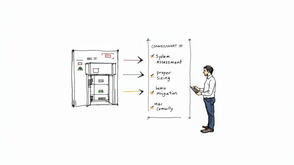
How to Select and Size Your Harmonic Filter
Choosing the right harmonic filter for a VFD isn't like grabbing a part off the shelf. It's an engineering task, plain and simple. Getting it right means finding that sweet spot between performance, cost, and compliance—solving your power quality headaches without breaking the bank.
If you over-engineer the solution, you're just wasting money. But if you under-engineer it, you’re leaving your whole facility exposed to the problems you were trying to fix. The process has to start with a deep dive into your electrical system and the VFDs causing the trouble in the first place.
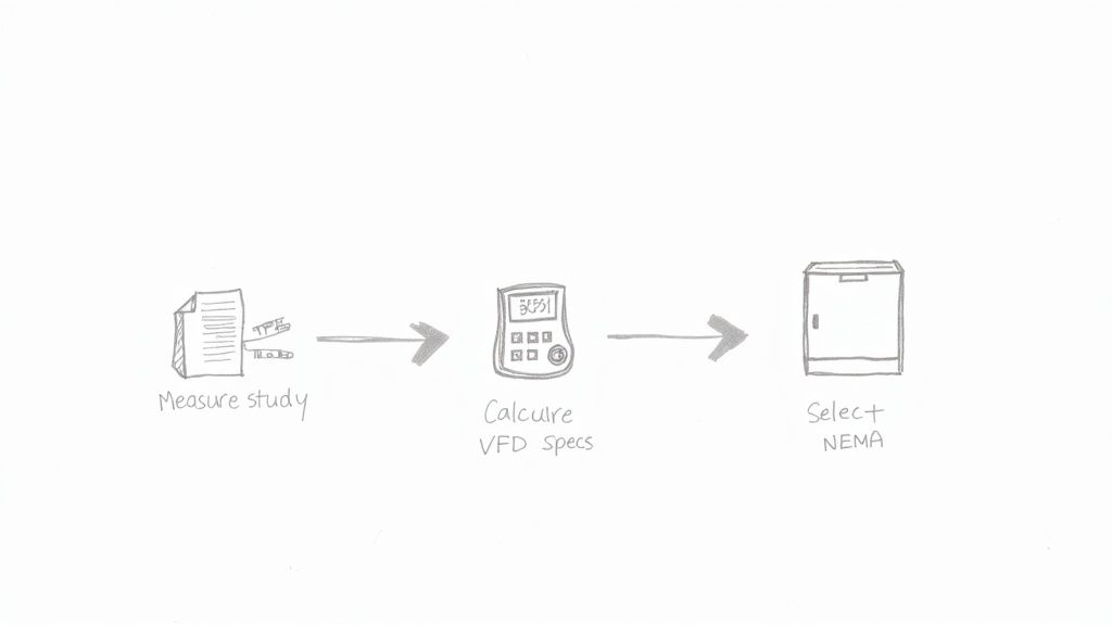
Start with a Power System Analysis
Before you can fix the problem, you have to know exactly what you're up against. A power system analysis is the non-negotiable first step. Think of it as a diagnostic for your electrical network—it gives you the hard data you need to make the right call.
It's a lot like a doctor ordering lab work before writing a prescription. A technician will hook up a power quality analyzer to measure the existing distortion, paying close attention to the Total Harmonic Distortion (THD). This shows you which harmonic frequencies are the biggest offenders and just how bad they are.
A detailed analysis is your roadmap. It shows you the starting line (your current THD) and the finish line (meeting standards like IEEE 519). With that map, you can pick the most direct and cost-effective route to clean power.
Trying to pick a filter without this data is just a shot in the dark. The analysis gives you the proof you need to justify the investment and guarantee the filter you choose will actually work.
Decode VFD and Motor Specifications
Once you have your system's harmonic profile, it’s time to zero in on the source: the VFD and the motor it’s running. Every piece of information here is a clue that helps you pick the perfect filter.
You’ll need to pull together a few key specs:
VFD Horsepower (HP) or Kilowatt (kW) Rating: This is your main sizing number. It tells you how much power the drive uses and, by extension, how much harmonic noise it's likely to create.
Full Load Amps (FLA): This is critical. The filter has to be rated to handle the motor's full current draw, day in and day out, without skipping a beat.
System Voltage: Make sure the filter's voltage rating is a match for your system, whether it’s 480V, 600V, or something else. A mismatch is a recipe for instant failure.
VFD Pulse Number: The vast majority of modern drives are 6-pulse VFDs. These are known for generating 5th, 7th, 11th, and 13th order harmonics, so you'll want a filter tuned to knock those down.
Putting this data together with your power system analysis gives you a complete picture. It allows engineers to accurately model the system and spec a filter that can handle the load. Taming those harmonic currents also has a nice side effect of cutting down on energy waste; you can learn more about how VFDs impact your power bill by reading about VFD energy savings on our blog.
Consider Environmental and Physical Factors
Even a perfectly sized filter can fail if you stick it in the wrong environment. It’s easy to overlook these physical factors, but they can dramatically shorten a filter's lifespan.
First up is the ambient operating temperature. Harmonic filters throw off their own heat. If the room they’re in is already hot, the unit might need to be derated or beefed up with extra cooling. Likewise, installations at high altitude have thinner air, which makes cooling less effective and often requires a bigger unit.
You also have to think about the right enclosure. The NEMA (National Electrical Manufacturers Association) rating tells you how well an enclosure protects the components inside from the surrounding environment.
NEMA 1: Your standard indoor enclosure for clean, dry spots.
NEMA 3R: Built for the outdoors, ready to stand up to rain and snow.
NEMA 4/4X: Watertight and tough enough for washdown areas. The 4X is stainless steel for fighting off corrosion.
NEMA 12: The go-to for dusty, dirty industrial shop floors where you might have dripping fluids.
Picking the right NEMA rating isn’t optional—it's a must for keeping your people safe and your equipment running for the long haul.
When you're installing a harmonic filter for a VFD, it’s not always just about cleaning up your own power. More often than not, it's about staying on the right side of the power quality standards set by your utility. The big one you’ll hear about constantly is IEEE 519. This is the rulebook that governs your relationship with the grid, making sure your plant’s electrical "noise" doesn't pollute the power for everyone else.
Think of the grid like a shared community lake. Everyone draws clean water from it. But VFDs, without filters, are like pipes dumping muddy water back in. IEEE 519 is the environmental agency for that lake, ensuring everyone's a good neighbor and keeps the water clean.
And this isn't just a friendly suggestion. If you ignore it, utilities can hit you with some serious penalties, force you into costly upgrades, or in extreme cases, even pull the plug on your facility.
Understanding the Point of Common Coupling
The entire world of IEEE 519 revolves around one specific spot: the Point of Common Coupling (PCC). This is simply the physical point where your facility plugs into the utility's grid. For most of us, that's the main electrical meter.
This is where the utility takes its measurements. They aren’t all that concerned with the harmonic chaos happening inside your four walls—their focus is on what you're exporting back to their grid. That little detail is everything, because it shapes your entire game plan for harmonic filtering.
Key Insight: Your real goal is to get a harmonic filter that cleans things up before the power hits the PCC. You need to meet the IEEE 519 limits at that specific point, so your internal VFDs don't become someone else's problem.
Essentially, the filter's job is to trap the harmonic distortion your drives create, keeping it contained within your facility so it never makes it out to the street.
What IEEE 519 Limits Actually Mean
The standard itself is a pretty dense read, full of charts and technical jargon. But what it asks of you boils down to two main limits, measured right there at the PCC:
Total Harmonic Current Distortion (THDi): This is the big one. It caps the amount of distorted current your plant can push back into the grid. The exact percentage allowed depends on your service size, but for most industrial plants, the magic number is keeping THDi below 5%.
Total Harmonic Voltage Distortion (THDv): This limits the voltage distortion on the utility’s lines. While your VFDs create current distortion, that current flows through the grid's impedance and can cause voltage distortion. This rule ensures you don't mess with the grid's stability.
Getting under that <5% THDi target is almost always the main reason for installing a harmonic filter. A good filter is specifically designed to take a system with messy, unfiltered harmonics—often in the 30-40% THD range or even higher—and wrestle it down into that compliant, clean zone.
The Importance of UL Listings and Other Certifications
Beyond just satisfying the utility, you have to think about safety and reliability. This is where certifications like a UL Listing (Underwriters Laboratories) come in. A UL stamp isn't just a sticker; it's proof from an independent third party that the filter has been rigorously tested and meets strict electrical safety standards.
When you see a UL-listed filter, you know it's been designed and built properly and is safe for its intended job. For anyone specifying equipment—whether you’re an OEM, a system packager, or a plant engineer—insisting on UL-listed components is a non-negotiable. It’s about covering your bases for code compliance, protecting your people, and reducing your liability. It's the seal of approval that says this equipment won't be the source of your next headache.
Getting Filter Installation and Commissioning Right
You can pick the perfect harmonic filter for a VFD, but if the installation is botched, you’ve wasted your time and money. Proper installation and commissioning aren't just boxes to check; they're the critical final steps that ensure the filter actually does its job, protecting your equipment and keeping your power clean from day one.
Getting this right is all about precision and process. It’s what separates a successful project with documented results from a frustrating, endless troubleshooting headache. A little extra care here pays massive dividends in long-term reliability and performance.
Critical Installation Details
Where and how you physically install the filter is foundational to its success. A few key details can make a night-and-day difference in how well it contains harmonic distortion and operates safely.
Location, Location, Location: The filter needs to be as physically close to the VFD as possible. Period. This simple rule minimizes the length of cable carrying the "dirty," high-harmonic current, effectively trapping that electrical noise at the source before it pollutes the rest of your facility's power system.
Wiring and Grounding are Non-Negotiable: Follow the manufacturer's wiring diagrams to the letter. Proper grounding isn't just a safety formality; it’s absolutely essential for the filter to function. A weak or improper ground connection can render a filter completely useless—or even create new power quality issues.
Don't Let It Cook: Harmonic filters generate heat as they work, absorbing and dissipating the energy from nasty harmonic currents. You have to make sure the enclosure has proper ventilation or cooling, just as the manufacturer specifies. Overheating is the number one killer of filters, causing premature failure of internal components like capacitors.
The Commissioning Process: A Step-by-Step Guide
Once the filter is physically installed, it's time for commissioning. This is where you prove it works and officially sign off on the project. Think of it as the final quality control check before you turn the system over to operations.
Pre-Flight Safety Checks: Before you even think about throwing the switch, do a thorough visual inspection. Look for any loose connections, double-check that the wiring matches the schematics, and confirm the enclosure is secured and grounded correctly. Make sure you have the required clearances for airflow.
Initial Power-Up and Monitoring: Start by energizing the system with no load or a very light load. Listen for any weird sounds, check for strange smells, or watch for any immediate temperature spikes. This kind of "soft start" lets you catch any major problems before the system is under full operational stress.
Verification with a Power Quality Analyzer: This is the moment of truth. You need hard data to prove the filter is working, and that means measuring the Total Harmonic Distortion (THD).
The heart of any commissioning process is the data. By taking "before" and "after" measurements with a power quality analyzer right at the Point of Common Coupling (PCC), you create undeniable proof that the harmonic filter is delivering and bringing your system into compliance with standards like IEEE 519.
A "before" reading might show a current THD of a whopping 35%. After the filter is commissioned, that number should be well below the 5% target. This data justifies the entire project, validates the investment, and gives you a solid baseline for any future maintenance or troubleshooting.
Without these measurements, you're just guessing.
Common Harmonic Filter Problems and How to Fix Them
Even the best-laid plans can go sideways. A perfectly specified harmonic filter for a VFD can still run into trouble out in the real world. Knowing what to look for is half the battle, helping you troubleshoot faster, slash downtime, and protect your gear.
The single most dangerous issue you can face is electrical resonance. It’s also the most misunderstood. This gremlin usually pops up with passive filters when their electrical personality clashes with the power system's own impedance. Instead of squashing harmonics, the filter starts to sing along, amplifying a specific harmonic frequency to catastrophic levels.
When this happens, you get wild voltage swings that can fry capacitors and cause a total system meltdown. The only true fix is prevention—a proper system analysis before you ever install. But if you even suspect resonance is happening, kill the power immediately and get an engineer on the phone.
Overheating and Nuisance Tripping
Two classic symptoms of a struggling filter are overheating and nuisance tripping. They're often related and are basically your system's way of telling you something is seriously wrong. An overheating filter is a dead giveaway that it's choking on more harmonic current than it was built to handle.
There are a few usual suspects:
System Creep: Someone added a few more VFDs or other harmonic-producing loads to the circuit after the filter was installed.
Bad Sizing: The filter was undersized from day one and just can't keep up with the drive's actual harmonic garbage.
No Room to Breathe: The filter is crammed into a hot panel with no ventilation, so it can't shed the heat it generates.
Nuisance tripping is what happens when the chaotic, distorted current waveforms trick your breakers. The breaker sees the jagged current, thinks it's a short circuit, and does its job—even though there's no real fault.
Troubleshooting Tip: Always start with the simple stuff. Before you break out the power analyzer, just check the filter's vents. Is there dust buildup? Is the cabinet door blocked? You’d be surprised how often a five-minute fix solves a "major" problem.
Steps for Effective Troubleshooting
When you've got a filter that isn't pulling its weight, don't just start swapping parts. A little structured diagnosis goes a long way.
Go Back to the Paperwork: Dig up the original design specs. Was the filter actually sized correctly for the VFD's horsepower and full-load amps?
Get New Readings: Hook up a power quality analyzer and measure the current THD both before and after the filter. The numbers don't lie—they'll tell you exactly how much work the filter is (or isn't) doing.
Check Every Connection: Get a wrench and a torque screwdriver. Check for any loose or corroded terminals on the filter, the VFD, and especially the ground. A single bad connection can bring the whole system to its knees.
By methodically working through these common issues, you can turn a failing harmonic mitigation system back into a reliable asset that protects your plant for the long haul.
Common Questions About Harmonic Filters for VFDs
When you start digging into the details of using a harmonic filter for VFD systems, a handful of practical questions always come up. Whether you're an engineer designing a system or part of the team keeping it running, getting clear answers is what really matters. Let's tackle some of the most common things we hear from people in the field.
These are the questions that bridge the gap between theory and the real world—from whether you really need a filter to how long you can expect one to last.
Do All VFDs Require a Harmonic Filter?
Not every single time, but in most industrial settings, it's a very smart move. The need goes from "highly recommended" to "absolutely critical" the moment you have sensitive electronics like PLCs on the same line, strict power quality rules (think hospitals or data centers), or a whole bunch of VFDs working together.
The only way to know for sure is to get the data. A power system analysis is the right tool for the job. It measures the harmonic distortion you already have and tells you if you're flirting with non-compliance or setting yourself up for equipment failure. It makes the decision black and white.
Expert Insight: Here’s a good way to think about it. A single VFD running a simple, isolated pump might not cause any trouble. But as soon as you have a facility full of drives, all that harmonic "noise" adds up. A filter becomes essential to keep the whole system stable and prevent those weird, intermittent problems that are so tough to track down.
Can a Harmonic Filter Improve Energy Efficiency?
Yes, and the savings can be significant. While knocking out harmonics is their main job, improving energy efficiency is a fantastic side effect. Harmonics are basically wasted energy causing extra heat to build up in your transformers, wiring, and motors.
By filtering that junk off the line, the VFD system doesn't have to draw as much current from the utility. One case study on a multi-VFD system showed that adding a passive harmonic filter cut energy use by a whopping 12.7%. Less heat loss means a lower electricity bill and a more efficient operation, plain and simple.
What Is the Typical Lifespan of a Harmonic Filter?
A well-built passive harmonic filter for a VFD is a true long-term investment. You can easily expect it to last 15-20 years, and often even longer. The guts of these things are just tough-as-nails inductors and capacitors—no moving parts, nothing to wear out. They're built to last.
Active filters have a similar operational lifespan, but they do have more electronics inside, like control boards and cooling fans. Those components might need some maintenance or replacement down the road to keep the filter running at its best.
Where Is the Best Place to Install a Harmonic Filter?
This one is critical: get the filter as close to the VFD as you possibly can. The reason is simple—you want to stop the harmonic noise right at the source.
Placing the filter right next to the drive keeps the "dirty," high-harmonic current contained in the shortest possible length of cable. This is huge, because it prevents that electrical noise from spreading all over your facility's power network and causing problems for every other piece of equipment plugged into it.
At E & I Sales, we live and breathe this stuff. We engineer robust, reliable motor control and power quality solutions every day. If harmonic distortion is giving you headaches, our team can help you pick, size, and integrate the perfect filter for your setup. Visit us online to see our custom UL control packaging and system integration services.
Think of a Variable Frequency Drive (VFD) as a smart throttle for your electric motors. Instead of running a motor at 100% speed all the time and using a mechanical valve or damper to choke the output, a VFD fine-tunes the motor's speed to match the exact demand of the moment. This simple but powerful principle is why VFDs consistently slash electricity consumption by 20% to 50% in the right applications.
Why VFDs Are a Must-Have for Industrial Energy Savings
Let's get practical and move past the textbook definitions. The old way of controlling motors in facilities with pumps and fans is just plain wasteful.
Imagine driving your car by flooring the gas pedal while simultaneously riding the brake to control your speed. You’d burn through a tank of gas in no time. That’s precisely what happens in a system where a motor runs full-tilt against a partially closed valve or damper. All that energy is just wasted as heat and noise.
A VFD completely flips that script. It gives you a precision accelerator for your motor, allowing it to ramp up or down to deliver only the power needed. This fundamental shift is the key that unlocks massive VFD energy savings.
The Sheer Scale of the Opportunity
The potential impact here is huge. Electric motors are the workhorses of industry, guzzling around 70% of all industrial electricity. This makes them the single biggest target for efficiency upgrades.
By intelligently matching motor output to the actual load, VFDs can take a serious bite out of that number. For instance, in common pump and fan systems, a seemingly small 20% reduction in motor speed can cut energy use by nearly 50%.
This guide will walk you through the science, the financial math, and the real-world best practices for putting VFDs to work. We'll cover everything from the basic principles to the common mistakes that can chip away at your return on investment.
Core Benefits of VFD Implementation
Installing VFDs delivers a lot more than just a smaller utility bill. The advantages ripple across your entire operation.
Drastic Energy Reduction: The most obvious win. VFDs directly cut kilowatt-hour (kWh) consumption by eliminating the wasted energy from running at a fixed, full speed.
Improved Process Control: Precision speed adjustments give you tighter control over your process, often leading to better product quality and more consistent system performance.
Reduced Mechanical Stress: The "soft start" capability of a VFD means no more jarring, across-the-line starts. This gentle ramp-up reduces wear and tear on motors, belts, and bearings, making your equipment last longer.
Lower Maintenance Costs: Less mechanical abuse means fewer breakdowns and lower maintenance spend over the life of the equipment. It’s that simple.
VFD Control vs Traditional Mechanical Control
To really see the difference, it helps to compare the two approaches side-by-side. The old method is about brute force, while the VFD approach is about intelligence and finesse.
Attribute
VFD Control
Throttling or Damper Control
Energy Efficiency
High; motor speed matches load, minimizing waste.
Extremely low; motor runs at full speed, excess energy is lost.
Control Precision
Excellent; allows for precise and dynamic speed adjustments.
Poor; offers crude, step-based control with high-pressure drops.
Mechanical Stress
Low; soft starting and stopping reduces wear and tear.
High; abrupt starts and stops cause significant mechanical shock.
System Flexibility
High; easily adapts to changing process demands.
Low; fixed-speed operation is rigid and inefficient.
Maintenance
Reduced; less stress on components leads to longer life.
Increased; higher stress accelerates wear on valves, bearings, and motors.
The table makes it clear: VFDs aren't just an upgrade; they represent a smarter, more sustainable way to manage motor-driven systems.
If you're just getting started, it helps to get a handle on the key components and how they work together. Our in-depth guide on Variable Frequency Drive basics is the perfect place to build that foundation.
How VFDs Turn Speed Reduction Into Big Savings
To really get why VFDs can slash energy bills, we have to look past the hardware and talk about a core principle in physics: the Affinity Laws. These laws are the playbook for how centrifugal equipment—think pumps and fans—operates. And they reveal a frankly stunning relationship between a motor's speed and how much power it guzzles.
You'd think that if you slow down a fan by 20%, you’d use 20% less energy, right? It seems logical, but that's not how it works. The relationship isn't a straight line; it's exponential, and that’s where the magic happens.
The Power of the Cube
The Affinity Laws lay it out clearly: the power a motor needs is directly proportional to the cube of its speed. This is the secret sauce behind the incredible savings a VFD delivers. A small tweak to the speed has an enormous impact on your power consumption.
Power ∝ (Speed)³. This is the key. That cubic relationship means even a modest drop in motor speed leads to a massive plunge in energy use. It's the whole reason VFDs are so effective for fans, pumps, and other variable torque applications.
This principle is what makes VFDs such a no-brainer. Instead of brute-forcing a system with mechanical dampers or throttling valves—which is like driving your car with one foot on the gas and the other on the brake—a VFD simply tells the motor to do less work. It's elegant and incredibly efficient.
A Real-World Ventilation Fan Example
Let’s put some real numbers on this. Picture a large ventilation fan in a factory. It’s designed to run full tilt, but for most of the day, the building only needs about 80% of its maximum airflow.
Without a VFD: The motor screams along at 100% speed, all day, every day. To cut the airflow, a mechanical damper closes, physically blocking 20% of the air. The motor is still working its heart out, fighting against that restriction, and all that wasted energy just turns into heat and noise.
With a VFD: Forget the damper. The VFD just slows the motor down to 80% of its full speed. Simple.
Now, let's plug that into the Affinity Law and see what happens to the power draw.
Speed Reduction:80% (or 0.8) of full speed.
Power Calculation: (0.8)³ = 0.8 x 0.8 x 0.8 = 0.512
By trimming the fan speed by just 20%, the VFD cuts the energy consumption all the way down to 51.2% of the original amount. That’s a jaw-dropping 48.8% reduction in power from a small change in output. This is exactly the kind of VFD energy savings that can completely change a facility's operating budget. If you want to dig deeper into the mechanics, our detailed article on https://eandisales.com/business/ac-motor-variable-speed/ is a great place to start.
Applications Beyond Industrial Fans
This powerful concept of matching speed to real-time demand isn't just for huge industrial machines. You see the same principle at play in all sorts of applications. For example, modern variable speed heat pumps use it to deliver huge comfort and efficiency gains in our homes.
The core idea is universal. Whenever demand isn't constant, adjusting speed is always smarter than running at full blast and choking the output. Whether it’s a massive water pump or a residential air conditioner, variable speed technology is the key. This is why understanding the Affinity Laws is so important—it takes the promise of VFDs from an abstract idea to concrete, bankable savings.
Calculating Your VFD Savings and Payback Period
Knowing the theory is one thing, but making a rock-solid business case requires real numbers. This is where we bridge the gap between the Affinity Laws and your facility's bottom line. By nailing down your potential VFD energy savings and the payback period, you can walk into any budget meeting with confidence.
The process isn't as complicated as it might sound. It's really just a "before and after" comparison. We'll figure out what a specific motor is costing you right now, then project the new, lower costs once a VFD is doing the work.
Let's run through a practical, real-world scenario to see exactly how the numbers shake out.
Step 1: Establish Your Baseline Energy Cost
First things first: you need to know your starting point. To do that, you’ll need to grab a few key pieces of data for the motor you’re looking to upgrade.
Motor Horsepower (HP): The rated power stamped right on the motor.
Operating Hours: How many hours per year that motor is actually running.
Electricity Rate: Your cost per kilowatt-hour (kWh), which you can find on your utility bill.
Motor Efficiency: The rated efficiency of your current motor, also usually on the nameplate.
To get the most accurate numbers, you have to track your energy use properly. Grabbing a good power consumption monitor is a smart move. It gives you the precise data you need for these initial calculations and for proving the savings later on.
A Worked Example: 100 HP Pump Motor
Let's put this into practice with a very common piece of equipment: a 100 HP pump motor that runs for 6,000 hours per year.
Here are our assumptions:
Motor HP: 100 HP
Conversion Factor: 0.746 kW per HP
Motor Efficiency: 94% (a standard for a premium efficiency motor)
Operating Hours: 6,000 hours/year
Electricity Rate: $0.12 per kWh
First, we calculate the power consumption in kilowatts (kW) when it's running flat out: Power (kW) = (100 HP * 0.746 kW/HP) / 0.94 efficiency = 79.36 kW
Next, let's figure out the total annual energy consumption in kWh: Annual kWh = 79.36 kW * 6,000 hours = 476,160 kWh
And finally, the total annual electricity cost without a VFD: Annual Cost (No VFD) = 476,160 kWh * $0.12/kWh = $57,139
That's right—running this single pump at full speed costs over $57,000 a year. That’s our baseline.
Step 2: Calculate Your VFD Energy Savings
Now, let's see what happens when we install a VFD. Let’s say that for half its run time (3,000 hours), the process only needs the pump to run at 70% speed. For the other 3,000 hours, it still needs to go full throttle.
This is where the magic of the Affinity Laws really kicks in.
As you can see, a small drop in speed creates a massive drop in power consumption. It's not a 1-to-1 relationship; it's a cubic one, which is what makes VFDs so powerful.
Let’s calculate the power draw at 70% speed using that cubed relationship (Power ∝ Speed³): Power at 70% Speed = 79.36 kW * (0.7)³ = 79.36 kW * 0.343 = 27.22 kW
Now we can calculate the new annual energy usage with the VFD in control:
New Total Annual kWh: 238,080 + 81,660 = 319,740 kWh
And the new annual cost: Annual Cost (With VFD) = 319,740 kWh * $0.12/kWh = $38,369
The savings are immediate and substantial: Total Annual Savings = $57,139 – $38,369 = $18,770
That's a 33% reduction in annual energy costs, just from matching the motor's speed to what the process actually needs. If you want to dive deeper into how different factors play into this, check out our resources on https://eandisales.com/tag/motor-efficiency/.
Step 3: Determine the Payback Period
The last step is the one everyone wants to see: how fast does this investment pay for itself? The simple payback period is just the total project cost divided by the annual savings.
Let's say the all-in installed cost for the VFD is $25,000. This covers the drive itself, any necessary filters, and professional installation.
Payback Period (Years) = Total Project Cost / Annual Energy Savings Payback Period = $25,000 / $18,770 = 1.33 years
A payback of just over 16 months makes this an incredibly compelling project. For some operations, it’s even faster. One ceramics factory in Poland, for instance, modernized its systems with VFDs and saw a payback in just seven months after achieving a 30% reduction in energy use. These kinds of results are becoming more and more common.
Common Mistakes That Undermine VFD Savings
Slapping a VFD on a motor isn't a silver bullet for your energy bills. While the potential for savings is huge, a few common and costly mistakes can chew right through your expected ROI, sometimes wiping it out completely. Getting real VFD energy savings means thinking about the drive as one part of a much bigger system.
Time and again, we see facilities make the same handful of errors, turning a promising efficiency project into just another frustrating expense. If you know what these pitfalls are ahead of time, you can steer clear and make sure your VFD project actually delivers the numbers you planned for. Let's walk through the four biggest mistakes we see out in the field.
Oversizing the Drive and Motor
It's a classic engineering impulse: build in a safety margin. But when it comes to VFDs and motors, "bigger" is almost never better. An oversized VFD—one rated for way more horsepower than the motor actually needs—ends up operating in a highly inefficient part of its performance curve. It wastes energy before it even gets to the motor.
It's the same story with an oversized motor. Forcing it to consistently run at less than 40% of its full rated load makes it incredibly inefficient. This habit doesn't just inflate your initial purchase price; it locks in an energy penalty that you'll pay for the entire life of the equipment.
The real secret is to size the VFD and motor for the actual work being done, not some theoretical maximum load that might happen once in a blue moon. Doing accurate load profiling before you buy anything is the single best way to dodge this expensive mistake.
Implementing a Poor Control Strategy
A VFD is only as smart as the instructions it gets. One of the most common ways we see savings evaporate is through a sloppy control strategy. This can show up in a few different ways, but each one chips away at your potential savings.
Running in "Hand" Mode: You'd be surprised how often a technician leaves a VFD in manual (or "Hand") mode, forcing it to run at a fixed speed. Often, that speed is 100%. This effectively turns your sophisticated VFD into a dumb motor starter, killing any chance of saving energy.
Incorrect Setpoints: If you set a pressure or flow setpoint higher than the system actually requires, you're forcing the VFD to run the motor faster than needed, 24/7. It's a constant, silent energy drain.
Forgetting About the Bypass: Most VFDs have a bypass contactor to run the motor across the line if the drive fails. If that bypass gets left on by mistake, all your potential savings are gone. The VFD is just an expensive box on the wall.
Proper commissioning from the start and regular check-ins are essential. You have to make sure the control logic is still optimized for savings and hasn't been overridden for convenience.
Ignoring the Broader System Context
A VFD can't fix a fundamentally flawed system. It’s a tool that optimizes a motor's performance within the existing mechanical setup. If that setup is inefficient, the VFD's impact will be severely limited.
Think of it like dropping a high-performance engine into a car with flat tires and a clogged exhaust. The engine has plenty of power, but the rest of the car is holding it back.
Here are some common system-level problems that hamstring VFDs:
High static head in pump systems: If a pump has to fight gravity just to lift water to a certain height, it has a high static head. This creates a hard floor on how much you can slow the pump down, which puts a ceiling on your potential savings.
Inefficient ductwork or piping: Clogged filters, undersized pipes, and poorly designed ductwork create a ton of resistance. This forces the motor to work harder than it should. A VFD can help, but you'll save far more if you fix these mechanical issues first.
You have to look at the whole picture. Before you even think about a VFD, analyze the entire mechanical loop to find and fix the blockages that will kill your savings potential.
Overlooking Power Quality Issues
Finally, don't forget that a VFD is a complex piece of electronics that has a real impact on your facility's electrical network. By their very nature, VFDs create harmonic distortion as a byproduct of how they work. Without the right mitigation, these harmonics can cause serious problems that erode your efficiency and reliability.
Harmonics can lead to transformers and wiring overheating, circuit breakers tripping for no apparent reason, and interference with other sensitive electronic gear. Every one of these issues introduces waste and eats into the VFD energy savings you were counting on.
Installing the right line reactors or harmonic filters isn't an optional add-on. It's a non-negotiable step to protect both your VFD investment and the health of your entire electrical system.
Getting Your VFD Installation and Verification Right
Realizing the full VFD energy savings you've been promised takes more than just bolting a drive to the wall. It’s all about a smart approach—thoughtful planning, a clean installation, and actually proving the results. Let’s walk through the playbook that separates a successful VFD project from a disappointing one.
The first, and most important, step happens before you ever order a drive. You have to get intimate with the application. Is it a fan or a pump? What’s the real-world operating load profile look like—not just the motor's nameplate rating? Answering these questions first confirms a VFD is even the right tool for the job and helps you size it for peak efficiency.
Smart Installation Strategies
Once you’ve got the green light, the focus shifts to a safe, reliable installation. This isn't the place to cut corners. Rushing the install is a fast track to performance headaches, safety risks, and equipment that dies an early death.
A hugely effective strategy is to opt for pre-engineered, UL-listed control panels. These aren't just boxes; they're integrated systems. The VFD, circuit protection, controls, and any necessary filters are all packaged together in a single, tested enclosure. This move ensures you're up to code, but just as importantly, it makes the field installation faster and drastically cuts down on the chance of wiring mistakes.
Don’t forget about harmonic mitigation. It’s easy to overlook, but VFDs naturally create electrical "noise" (harmonics) that can wreak havoc on other sensitive equipment on your network. Installing the right line reactors or harmonic filters isn't an optional upgrade. It's a non-negotiable part of a professional install that protects your entire facility.
The Make-or-Break Role of Commissioning
This is where the magic happens. Proper commissioning is the process that turns theoretical savings into actual dollars. It involves a skilled technician dialing in the VFD’s parameters to perfectly match what your system needs. They’ll tweak things like acceleration/deceleration ramps, set proper speed limits, and fine-tune PID loop controls so the motor runs as lean as possible.
This is absolutely not a "set it and forget it" task. Commissioning is about making sure your control strategy perfectly mirrors your system’s real demands. It prevents common energy-wasters like running at a setpoint that’s too high or having the motor constantly "hunt" for the right speed. Skipping this is like buying a race car and never taking it out of first gear.
Prove Your Savings: Measurement and Verification
So, how do you actually know if the VFD is saving you money? You prove it. That’s what Measurement and Verification (M&V) is all about—tracking performance to put a hard number on your savings. This step is critical for calculating your ROI and making the case for the next efficiency project.
You can tackle M&V in a few ways:
Onboard VFD Data: Most modern drives are smart enough to log key data like kWh consumed, run hours, and operating speeds. It’s a simple, built-in way to keep tabs on energy use.
External Power Meters: For rock-solid, undeniable proof, installing a dedicated kilowatt-hour meter on the VFD’s input is the gold standard. The numbers don't lie.
Baseline Comparison: The whole point of M&V is to compare the "after" with the "before." By putting your new energy numbers up against the baseline data you gathered pre-VFD, the reduction in consumption becomes crystal clear.
This isn't just theory. A project in the mining sector found that swapping to VFD-controlled pumps slashed their energy costs by nearly 20%. That added up to over $3 million in cumulative savings in 15 years. This is the power of verifying your results—it confirms the financial win and the benefit of longer equipment life. You can dig into the case study on these VFD savings in mining operations.
Answering Your Top Questions About VFDs
When you start digging into VFDs for your facility, a lot of practical questions pop up. It’s only natural. Here, we'll tackle the most common ones we hear from plant managers and engineers in the field, using what we've already covered to give you straight, clear answers. The goal is to help you feel confident about the decisions you’re making to unlock real energy savings.
Will a VFD Save Energy on Any Motor?
This is a fantastic question, and the short answer is no—at least, not in the same way. The real savings potential from a VFD comes down to what kind of work the motor is doing.
VFDs shine brightest when they're paired with "variable torque" loads. Think of your centrifugal pumps and fans. These machines are a perfect match for the Affinity Laws we talked about earlier, where a small drop in speed leads to a massive drop in energy consumption. This is the VFD sweet spot, where cutting energy use by 30% to 50% is a totally realistic goal.
Then you have your "constant torque" loads. This includes equipment like conveyors, positive displacement pumps, or industrial mixers. The savings here are much more straightforward and directly proportional to the speed reduction. If you slow a conveyor down by 20%, you’ll save roughly 20% on energy. Those savings are definitely worth having, but you won't see the same exponential impact you get with fans and pumps.
The Bottom Line: Before you do anything else, identify your load type. Knowing if you have a variable or constant torque application is the single most important factor in figuring out if a VFD project will pay off.
So, How Much Energy Can I Actually Save?
The honest-to-goodness answer? It all comes down to your application's load profile. A VFD only saves you money when your process allows it to slow the motor down. The more time that motor spends running below full speed, the more cash you'll see back in your operating budget.
Let's imagine two scenarios with the exact same fan motor:
The High-Variation System: A building's ventilation system runs at 60% speed for 12 hours overnight and then ramps up to 100% for 12 hours during the day. This setup is going to see huge savings because it's leaning heavily on those Affinity Laws for half its life.
The Low-Variation System: A process fan has to run at 95% speed nearly all day, only kicking up to 100% every so often. A VFD will still give you great control, but the energy savings will be pretty slim because the speed reduction is just too small.
The key isn't just bolting on a drive; it's understanding how much your process really needs to vary. A good, hard look at your system's demand cycle is the only way to get a realistic savings forecast.
Doesn't the VFD Itself Use Power?
It sure does. A VFD is a complex piece of power electronics, and just like any other electronic device, it has some minor efficiency losses. It's constantly converting AC power to DC, then chopping it back up into a simulated AC waveform to control the motor.
A modern, high-quality VFD is typically about 97-98% efficient. That means it consumes a small slice—around 2-3%—of the power that passes through it.
But here’s the crucial part: that tiny internal loss is a drop in the bucket compared to the massive system-level savings the VFD makes possible. For any well-chosen variable torque application, the energy you save by slowing the motor down will absolutely dwarf the small amount the drive itself uses. The net result is always a big win for your energy bill.
What Are the "Hidden Costs" of a VFD Project?
Budgeting for a VFD means looking past the sticker price of the drive itself. A handful of other components and services are almost always needed to get the job done right and ensure the system is reliable for the long haul. Getting these on your radar from the start gives you a much more accurate picture of the total project cost.
Here are the usual suspects to account for:
Professional Installation: A VFD isn't a toaster you just plug in. It needs proper wiring, grounding, and controls integration by a qualified electrician who knows what they're doing.
Shielded Motor Cable: To keep the VFD from creating electrical "noise" (EMI/RFI) that can mess with other sensitive equipment in your plant, you'll often need special shielded cable running from the drive to the motor.
Harmonic Mitigation: As we've covered, VFDs can pollute your electrical system with harmonics. Depending on the existing power quality in your facility, you might need to add a line reactor or a harmonic filter to keep everything running smoothly.
Commissioning & Programming: This is a big one. A qualified technician needs to program the drive's parameters to perfectly match your motor and application. This step is what truly optimizes performance and makes sure you hit your VFD energy savings targets.
Bypass Contactors: For critical processes that can't ever go down, a bypass is often installed. This lets you run the motor directly off the line if the VFD ever fails, guaranteeing uptime.
Factoring in these items ensures your project isn't just up and running, but that it's also safe, reliable, and built to last.
At E & I Sales, we don’t just sell VFDs out of a box. We engineer complete solutions inside UL-listed control panels, designed and built to make your project a success from day one. If you're ready to stop talking about savings and start seeing them, let's have a conversation.
Controlling the speed of an AC motor is one of the most powerful tools we have in modern industrial automation. Without it, you’re stuck in an all-or-nothing world. With it, you unlock incredible precision and slash energy costs. The secret sauce is almost always a Variable Frequency Drive (VFD), a device that works by changing the electrical frequency fed to the motor.
Why Variable Speed Control Is Essential for Modern AC Motors
Picture trying to drive your car with only two options: idle or flooring it. That’s exactly what running a traditional, fixed-speed AC motor is like. It’s either off or running at full tilt, no matter what the job actually requires. This brute-force approach is shockingly inefficient and puts a ton of stress on your equipment.
That’s where AC motor variable speed comes in. It’s like adding a gas pedal to that car. Instead of lurching from a dead stop to maximum RPM, you get smooth, precise control over the motor's speed. You can match its output exactly to what the process needs at any given moment. This simple change is a game-changer for both performance and your bottom line.
The Problem with Fixed-Speed Operation
Running a motor at a single, locked-in speed creates two massive headaches for any industrial operation:
Massive Energy Waste: Think about a fan or pump that only needs to run at 60% capacity. A fixed-speed motor still screams along at 100%, forcing you to use mechanical dampers or valves to choke off the excess flow. It’s the industrial equivalent of flooring the accelerator and riding the brake at the same time—a colossal waste of energy.
Accelerated Mechanical Wear: The sudden, high-torque jolt of a fixed-speed motor starting up sends a shockwave through the entire system. This violent startup puts immense stress on belts, gears, couplings, and bearings. The result? Premature failures, more frequent maintenance, and expensive, unplanned downtime.
The Variable Speed Solution
Bringing variable speed control into the picture solves both problems cleanly. The go-to technology for this is the Variable Frequency Drive (VFD). By dialing the motor's speed up or down to meet the real-time demand, a VFD makes sure the system uses only the energy it absolutely needs. Nothing more.
This isn't just a minor tweak; it's a fundamental shift in how we design and run industrial systems. The market reflects this, with VFD sales valued at around $29.8 billion in 2025 and on track to hit $39.67 billion by 2030. That growth is fueled by undeniable benefits: energy savings often fall between 20% and 50%, and the level of process control you gain is simply unmatched. You can dig into the full market research on VFD growth to see just how big this shift is.
Key Takeaway: Moving to variable speed control isn’t just an equipment upgrade. It’s a strategic decision to cut energy consumption, make your machinery last longer, and fine-tune the performance of your entire operation. You're trading brute force for intelligence and efficiency.
Let's take a quick look at how these two approaches stack up side-by-side.
Fixed Speed vs Variable Speed AC Motors At a Glance
The table below breaks down the core differences between a simple, direct-on-line motor and one controlled by a VFD. It quickly becomes clear why variable speed has become the standard for so many applications.
Attribute
Fixed-Speed Motor
Variable-Speed Motor (with VFD)
Speed Control
Runs at a single, constant speed
Speed is fully adjustable from near-zero to full RPM
Poor at partial loads; energy wasted through throttling
Excellent; power consumption matches the actual load
Process Control
Very limited; requires mechanical controls (valves, dampers)
Highly precise; speed directly controls process output
Mechanical Wear
High due to harsh starts and stops
Significantly reduced due to soft starting/stopping
Cost
Lower initial equipment cost
Higher initial cost, but lower lifetime operating cost (TCO)
Typical Use Cases
Simple, constant-load applications (e.g., a conveyor always running at one speed)
Pumps, fans, compressors, mixers, and any process with varying demand
While the upfront investment for a VFD system is higher, the long-term savings in energy and maintenance almost always deliver a rapid and compelling return on investment. It's a classic case of spending a little more now to save a lot more later.
How a VFD Unlocks Variable Speed in AC Motors
The secret to controlling an AC motor's variable speed is baked right into its physics. An AC induction motor's speed is directly locked to the frequency of the power you feed it. Here in North America, our grid delivers a steady, unwavering 60 Hertz (Hz), which means a standard motor is designed to run at a fixed, synchronous speed. If you want to change that speed, you have to change the frequency.
That's exactly what a Variable Frequency Drive (VFD) is built to do.
A VFD isn't some glorified dimmer switch; it's a sophisticated piece of power electronics that sits between the wall outlet and your motor. It takes the fixed-frequency, fixed-voltage power from the grid, completely deconstructs it, and then builds a brand-new, fully adjustable AC power source for the motor.
By precisely dialing the output frequency up or down, the VFD can tell the motor to run at nearly any speed you need—from a slow crawl all the way up to its maximum rated RPM, and sometimes even a little beyond. This gives you an incredible amount of control over your process, whether it's a pump, a fan, or a complex conveyor system.
The Three-Step Power Conversion Process
The real magic of a VFD happens in three distinct stages. It's a clever process of breaking down raw grid power and then reconstructing it into a finely-tuned output that's perfect for the job at hand.
This infographic gives you a simple visual of how power flows from the source, through the VFD, and on to the motor.
The VFD is the "translator" in the middle, making variable speed possible. Let's peek inside that box and see how it works.
The Rectifier (AC to DC Conversion): First, the VFD grabs the standard AC power coming in and runs it through a rectifier. This section uses a series of diodes that act like one-way electrical gates, converting the alternating current (AC) into direct current (DC). It effectively smooths out the AC sine wave into a stable DC voltage. This DC power gets stored in large capacitors, creating a smooth energy reservoir called the DC bus.
The DC Bus (Power Filtering): Think of the DC bus as a buffer tank for electricity. The capacitors here filter out any leftover ripples from the rectification process, ensuring the next stage gets a clean, consistent DC voltage to work with. A stable DC bus is absolutely critical for creating a clean, high-quality AC waveform on the output side.
The Inverter (DC to AC Synthesis): This is where the real control happens. The inverter section is packed with high-speed transistors (typically IGBTs) that can switch on and off thousands of times per second. By controlling this rapid switching pattern with a technique called Pulse Width Modulation (PWM), the inverter can build, or synthesize, a brand-new AC sine wave from the DC voltage. The crucial part? The VFD can create this new wave at any frequency and voltage it needs, giving it total command over the motor's speed and torque.
The V/Hz Principle: The Foundation of Control
The most common and straightforward control method a VFD uses is called Volts-per-Hertz (V/Hz). It's based on a simple principle: an AC motor needs a specific magnetic field strength to work correctly, and this field is created by the ratio of voltage to frequency. To keep the motor happy and producing constant torque without overheating, you have to keep that ratio constant.
Take a standard 460-volt, 60 Hz motor. Its ideal V/Hz ratio is 7.67 (460 divided by 60). If the VFD slows the frequency down to 30 Hz to run the motor at half speed, it must also proportionally drop the voltage to 230 volts to maintain that same 7.67 ratio. This keeps the motor's magnetic field consistent and allows it to produce reliable torque across its entire speed range.
The V/Hz method is the workhorse for variable-torque loads like centrifugal fans and pumps, where the torque needed drops off dramatically as the speed decreases. It's simple, incredibly reliable, and perfect for a huge number of industrial applications.
Advancing to Vector Control for Precision Torque
While V/Hz control is great for many jobs, some applications need more muscle and finesse, especially at very low speeds or when the load is constantly changing. For these demanding tasks, we turn to more advanced algorithms like vector control, also known as field-oriented control.
Vector control is a much smarter method that uses a complex mathematical model of the motor running inside the VFD's processor. It allows the drive to independently manage the voltage and frequency to control two things separately: the motor's magnetic flux and its torque-producing current.
Key Insight: Imagine V/Hz control is like having a single knob that adjusts speed and power together. Vector control is like having two separate, highly precise knobs—one for the magnetic field strength and one for pure torque. This gives you far better response and finer control.
This advanced control method opens up some serious performance capabilities:
Full Torque at Zero Speed: A motor under vector control can deliver 100% of its rated torque even when it's standing still. This is non-negotiable for applications like cranes that need to hold a heavy load in place or for starting a high-inertia conveyor without a jerk.
Faster Dynamic Response: It can react almost instantly to sudden changes in load, keeping the motor speed incredibly stable.
Improved Efficiency: By actively managing the motor's magnetic field, vector control can optimize energy use, particularly when the motor is running under a light load.
This level of performance makes vector control the only real choice for high-demand machinery like CNC machines, extruders, and web-handling lines where precise tension and speed are critical to making a quality product.
What Happens to Performance When You Vary the Speed?
Using a VFD to control an AC motor's variable speed isn't just like turning a volume knob. It fundamentally rewrites the rules of how that motor operates. Sure, the benefits of precise speed control are massive, but this control introduces new thermal, electrical, and mechanical stresses that every good engineer needs to anticipate.
When you start playing with the motor's speed, you're directly messing with its two most important capabilities: torque and horsepower. This relationship isn't a simple straight line; it's a tale of two distinct operating zones. Getting a handle on these zones is the key to predicting how your motor will behave in the real world.
Constant Torque vs. Constant Horsepower: A Tale of Two Ranges
Think of a VFD-controlled motor as having two primary performance modes. These modes define exactly how much work the motor can do at any given speed without cooking itself.
Constant Torque Range (Everything Below Base Speed): From a dead stop all the way up to the motor's nameplate speed (typically what you get at 60 Hz), the VFD works its magic by keeping the Volts-per-Hertz ratio steady. This is huge because it means the motor can deliver its full rated torque no matter how slow or fast it's spinning within this range. As speed climbs, horsepower rises right along with it. This makes it perfect for heavy-lifting jobs like conveyors, mixers, and positive displacement pumps that need consistent muscle.
Constant Horsepower Range (Going Above Base Speed): What if you need to run faster than the nameplate speed? A VFD can do that by pushing the frequency past 60 Hz. But there's a catch. The motor's voltage is already maxed out, so the V/Hz ratio starts to drop. This phenomenon, known as "field weakening," causes the motor's available torque to fall off as speed increases. The horsepower, however, stays constant. This trade-off is ideal for applications like machine tool spindles, where you're prioritizing blistering speed over raw turning force.
If there's one thing to remember, it's this: running a motor below its base speed gives you consistent turning force. Running it above base speed gives you consistent power, but you sacrifice torque. For most industrial applications, you'll be sizing your motor to handle the required load within that constant torque range.
The Hidden Danger: Low-Speed Overheating
One of the most common—and destructive—gotchas in VFD applications is motor overheating at low speeds. Your standard, off-the-shelf TEFC (Totally Enclosed Fan-Cooled) motor has a simple cooling system: a fan bolted to the motor shaft. At full speed, it works beautifully, pulling plenty of air across the motor's cooling fins.
But what happens when you slow that motor down to 25% of its rated speed? The fan is also spinning at a measly 25%, and the airflow drops to almost nothing. Meanwhile, the motor is still generating heat from the current running through its windings. With its cooling system crippled, the motor's internal temperature can skyrocket, leading to fried insulation and a premature death.
This is exactly why inverter-duty motors have become the gold standard for any serious VFD setup. These motors are built for the job, often featuring:
Upgraded winding insulation designed to handle higher temperatures.
More efficient designs that produce less waste heat in the first place.
Separate, constant-speed cooling fans (often called force-ventilation or "blower-cooled" kits) that deliver full cooling no matter how slowly the motor shaft is turning.
Dealing with the Noise: Electrical and Audible
The high-frequency switching that happens inside a VFD's inverter is what makes modern motor control possible, but it doesn't come for free. This rapid-fire switching creates side effects you need to plan for.
Audible Motor Noise: That high-pitched whine you sometimes hear from a VFD-driven motor? That's the VFD's PWM (Pulse Width Modulation) frequency causing the motor's steel laminations to physically vibrate. While it's usually not harmful to the motor, it can be incredibly annoying in quiet environments. Luckily, most modern VFDs let you adjust the carrier frequency to push that noise outside the range of human hearing.
Electrical Noise (EMI/RFI): A VFD is also a potent source of electromagnetic interference (EMI) and radio frequency interference (RFI). This electrical "noise" can radiate out from the motor cables and play havoc with nearby sensitive electronics like PLCs, sensors, and communication networks. This is non-negotiable: you must follow best practices, like using properly terminated shielded VFD cable and establishing a rock-solid grounding system, to keep this noise contained.
The push for this kind of smart, efficient motor control is a huge force in the industry. It’s a key reason the global electric AC motors market, valued at $140.77 billion in 2025, is on track to hit $215.81 billion by 2032. This explosive growth is happening because integrating VFDs has shifted from a niche specialty to a standard practice for building better, more efficient machines. You can dive deeper into these trends by checking out market insights on ResearchAndMarkets.com.
How to Select and Size Your VFD and Motor
This is where the rubber meets the road. Picking the right components for an ac motor variable speed system isn't just about matching the horsepower on the motor's nameplate to the drive. That's a classic rookie mistake, and it's a fast track to poor performance and equipment that just doesn't last.
A solid design always starts with a deep dive into what the application is actually doing. The single most important first step is getting a handle on your application's load profile. This tells you how much torque the motor needs to produce at different speeds, which in turn dictates the kind of VFD you need.
It's a bit like choosing a vehicle—you wouldn't pick a sedan to haul a ton of bricks. Getting the load profile wrong is just as foolish.
Understanding Your Load Profile
Almost every industrial job falls into one of three buckets. Each one has its own quirks that will directly shape your VFD and motor choice.
Variable Torque (VT) Loads: These are your bread and butter—the most common and energy-efficient applications out there. Think centrifugal pumps and fans. With these, horsepower demand varies with the cube of the speed, and torque varies with the square of the speed. What does that mean in the real world? Even a small drop in speed can lead to massive energy savings.
Constant Torque (CT) Loads: Here, the motor needs to deliver consistent turning force, no matter how fast or slow it's running. Conveyors, mixers, extruders, and positive displacement pumps are perfect examples. They need full grunt to get a heavy load moving from a dead stop and keep it chugging along.
Constant Horsepower (CP) Loads: You won't see these as often, but they're critical in certain niches. These loads need a ton of torque at low speeds and much less at high speeds. Think machine tool spindles and center-driven winders. In these setups, the VFD is often running the motor above its base speed.
For the vast majority of jobs, you’ll be sizing for either Variable or Constant Torque. Many VFDs are even dual-rated. A single drive might be rated for 10 HP on a simple fan (VT) but only 7.5 HP on a heavy conveyor (CT). Always, always size based on the correct load.
Creating a System Sizing Checklist
Once you've pegged the load type, it's time to get into the nitty-gritty operational details. Running through a checklist like this is the best way to avoid expensive mistakes and make sure your system is tough enough for the long haul.
Answering these questions upfront is the difference between a system that just runs and a system that runs reliably and efficiently for years. Don't guess—get the hard data from the mechanical system requirements.
Use this as your framework:
Required Speed Range: What are the absolute minimum and maximum speeds you need? Is the motor going to be crawling along at low speeds for long periods where it could overheat?
Starting Torque: Does this thing need to start under a full load? A loaded conveyor, for example, might demand up to 150% of the motor's rated torque just to get rolling.
Braking and Deceleration: How fast does it need to stop? A high-inertia load like a big centrifuge or flywheel can generate a lot of back-EMF during a quick stop. You might need dynamic braking resistors to burn off that extra energy and prevent the drive from tripping.
Environmental Conditions: Where is this system going to live? High altitudes have thinner air, which hurts cooling and forces you to derate both the VFD and the motor. Extreme heat or cold will also heavily influence your component choices and enclosure design.
Why Inverter-Duty Motors Are Non-Negotiable
Let me be crystal clear on this last point: you absolutely must pair your VFD with a motor designed for it. Standard, off-the-shelf motors are not built to handle the unique electrical stresses that a VFD spits out. Using one is a gamble, and it's one that rarely pays off.
An inverter-duty rated motor is specifically built to take the abuse of the high-frequency voltage pulses from a VFD. They have much beefier winding insulation (often called "spike-resistant") and other design upgrades that prevent them from frying prematurely. For anyone looking at new or replacement units, you can find a wide selection of tough electric motors designed for exactly this kind of variable speed work.
Spending a little extra on the right motor from the get-go is the single best investment you can make in the reliability of your entire system.
Best Practices for VFD Panel Integration and Wiring
There’s an art and a science to integrating a Variable Frequency Drive (VFD) into a control panel. It’s the moment a standalone component becomes the reliable heart of your entire system. Get the physical layout and wiring right from the jump, and you’ll sidestep a ton of frustrating issues down the road—think electrical noise, overheating, and premature failures.
The success of any ac motor variable speed system really comes down to sweating these details. Think of the control panel as the VFD's life-support system. It needs clean power, cool air, and a rock-solid ground connection to do its job day in and day out without a hiccup.
Managing Heat Dissipation
A VFD running hard puts out a surprising amount of heat. If you just trap that heat inside a sealed panel, you're asking for trouble. Good thermal management isn't a "nice-to-have"; it's absolutely critical for the drive's health and reliability.
Here’s what really matters:
Respect the Clearances: Every manufacturer specifies minimum clearances above, below, and on the sides of their VFDs. That isn't a suggestion. This space is vital for natural air convection and keeps hot spots from forming.
Get the Air Moving: You'll almost always need fans. Make sure they're placed to create a smart airflow path, usually pulling cool air in from the bottom of the enclosure and pushing hot air out the top.
Size the Enclosure Right: Don't try to shoehorn a powerful VFD into a tiny box to save a few inches. A larger enclosure gives you more surface area to radiate heat and a bigger volume of air to act as a buffer, keeping internal temps stable.
Routing Wires to Prevent Electrical Noise
The high-frequency switching inside a VFD can create a storm of electromagnetic interference (EMI). If you don't contain it, this "noise" can play havoc with your low-voltage control signals from PLCs, sensors, and network cables, causing all sorts of erratic behavior.
Critical Best Practice: Always, always, always keep your power and control wiring physically separated. Never run motor leads and encoder cables in the same conduit. This one step is probably the most effective thing you can do to kill EMI problems before they start.
Using a good shielded VFD cable is your best weapon here. This purpose-built cable has a braided or foil shield that, when properly grounded at both the drive and the motor, acts like a cage, trapping the electrical noise and stopping it from radiating out.
Connecting VFDs to Control Systems
Once you’ve got the hardware squared away, it’s time to connect the VFD to the brains of the operation—the PLC or HMI. This is the communication link that makes real automation possible.
You've got two main ways to do this:
Simple I/O (Input/Output): This is the old-school, straightforward method. You might wire a PLC relay to a VFD digital input for a simple "run" command and use a 4-20mA or 0-10V analog signal to tell it how fast to go. It’s simple and effective.
Industrial Networks: For tighter control and better diagnostics, nothing beats an industrial network. Protocols like EtherNet/IP or Modbus TCP/IP let you manage speed, direction, and accel/decel ramps—plus read back vital data like motor current, fault codes, and runtime—all over a single ethernet cable.
This level of connectivity is what modern automation is built on. For projects that demand this kind of tight coordination, our expertise in system integration is what bridges the gap between individual parts and a fully commissioned machine. You see it everywhere, like in the HVAC world, where the variable frequency drive market hit $3.3 billion in 2024 by using VFDs for precise fan and pump control, slashing energy use by up to 30%. You can discover more insights about the HVAC VFD market on imarcgroup.com.
Getting Your Drive Running: Commissioning and Troubleshooting
Getting the VFD mounted and wired is one thing, but the real work begins at startup. A careful, methodical commissioning process is the absolute best way to head off frustrating faults and make sure your ac motor variable speed system is ready for the long haul. Think of it as laying the foundation for reliable performance from day one.
And let's be realistic—sooner or later, you're going to see a fault code. It's just part of life on the plant floor. Knowing how to quickly read the signs and solve common VFD issues is a must-have skill for any technician. It’s the difference between a five-minute fix and a full-blown production shutdown.
A Smart Commissioning Checklist
Before you flip the main breaker and let it rip, a systematic check-up is non-negotiable. This isn't just about being safe; it's about making sure every wire, parameter, and connection is perfect so the drive and motor can work together seamlessly. A rushed startup is just asking for trouble.
Follow these key steps to get things running smoothly:
Check Your Wiring Like a Hawk: Go over every connection again. Is incoming power landed correctly? Motor leads? Control I/O? Make absolutely sure your grounds are solid and that shielded cable is properly terminated to keep electrical noise from wreaking havoc.
Bump the Motor: This is a classic for a reason. With the motor uncoupled from the load, give it a quick "bump" at a super low speed—just 2-3 Hz. All you're doing is confirming it spins the right way. If it's going backward, just swap any two of the three motor leads (T1, T2, T3). Easy fix.
Run an Autotune: Don't skip this. This is where the VFD runs a quick diagnostic on the motor to learn its exact electrical personality. It builds a precise digital model of the motor, which is what allows advanced vector control to deliver that crisp torque and peak performance you're paying for.
An autotune is basically the VFD's handshake with the motor. If you skip it, the drive is just guessing, which leads to sloppy control, wasted energy, and poor performance.
Tackling the Most Common VFD Faults
When a drive trips, that little fault code on the screen is your first and best clue. Understanding what these codes mean and where to look first is the key to getting back online fast. For those really tricky problems in highly integrated systems, sometimes bringing in expert help for custom controls can quickly get to the bottom of things.
Here are the three most common faults you'll run into and what to do about them:
Fault Type
What's Likely Happening
How to Fix It
Overcurrent (OC)
The VFD is trying to accelerate the load too quickly, demanding more current than it can safely provide.
Stretch out the acceleration ramp time. Give the motor a little more time to get the load up to speed.
Overvoltage (OV)
During deceleration, the load's momentum is turning the motor into a generator, sending voltage back into the drive.
Increase the deceleration time. If that's not an option, you'll need a dynamic braking resistor to burn off that extra energy.
Motor Overheating
You're running the motor at low speeds for long periods, and the built-in fan can't move enough air to cool it properly.
First, confirm the motor is "inverter-duty" rated. If it is, you may need to add a separate, constant-speed blower fan (force ventilation) to keep it cool.
A Few Common Questions About AC Motor Speed Control
When you're out in the field planning a new setup or trying to figure out what's wrong with an existing one, a few questions always seem to pop up. Let's tackle some of the most common ones we hear from engineers and techs.
Can I Just Slap a VFD on a Standard AC Motor?
Technically, yes. Should you? For anything you want to last, absolutely not. Standard, off-the-shelf motors just weren't designed to handle the kind of electrical stress a VFD dishes out.
The drive's rapid-fire voltage pulses are brutal on standard winding insulation and can create damaging bearing currents that will kill the motor surprisingly fast. For any real-world application, you need an "inverter-duty" or "VFD-rated" motor. They're built tougher, with better insulation and other features designed from the ground up to take the abuse from a VFD and keep on running.
What’s the Real Difference Between V/Hz and Vector Control?
Think of V/Hz (Volts-per-Hertz) as the simple, "good enough" method. It keeps the voltage-to-frequency ratio constant, which works perfectly for basic loads like fans and centrifugal pumps where you don't need pinpoint precision. It gets the job done without a lot of fuss.
Vector control, on the other hand, is the brains of the operation. It's a much smarter algorithm that creates a detailed mathematical model of the motor inside the drive.
This allows the VFD to control the motor's torque and speed independently and with incredible precision, even down to zero speed. It's an absolute must for tough jobs like conveyors, cranes, and machine tools that need full muscle right from a dead stop.
How Far Away Can I Mount the Motor from the VFD?
Distance is a bigger deal than most people think. The longer the cable run, the more you have to worry about a nasty phenomenon called "reflected waves." These are voltage spikes that can bounce back from the motor and build up to levels high enough to fry the motor’s insulation.
As a rule of thumb, most drive manufacturers draw the line somewhere around 50-100 feet. Go beyond that, and you're asking for trouble unless you add some protection. For those longer runs, you'll need to install something like a load reactor or a dV/dt filter right at the VFD's output. Your drive's manual is your best friend here—always check it for specific limits and what it recommends for filtering.
When Do I Actually Need Dynamic Braking?
You need dynamic braking anytime you have to stop a heavy, high-inertia load faster than it would on its own. When you command a fast stop, the motor's momentum turns it into a temporary generator, pumping electricity back into the VFD. This can easily overwhelm the drive and trigger an overvoltage fault, shutting everything down.
A dynamic braking resistor gives all that excess energy a safe place to go, burning it off as heat. It’s essential for things like centrifuges, massive industrial fans, or loaded downhill conveyors that need to stop on a dime.
At E & I Sales, we live and breathe this stuff. We provide the tough motors, UL-listed control panels, and the integration expertise to build variable speed systems that just plain work. Contact us today to discuss your next project.