Think of industrial controls automation as the central nervous system of a modern factory. It’s the combination of hardware and software that orchestrates everything from a single robotic arm to an entire production line. This isn't about replacing people; it's about replacing manual, repetitive oversight with intelligent, consistent processes that just work.
What Is Industrial Controls Automation?
At its heart, industrial controls automation is about giving machinery a brain. Walk into any advanced manufacturing plant today, and you won't see hundreds of operators flipping switches or turning dials. What you will see is a symphony of motion, precision, and speed, all thanks to a carefully designed network of automated systems.
This is the invisible force that guarantees the thousandth product off the line is identical to the first.
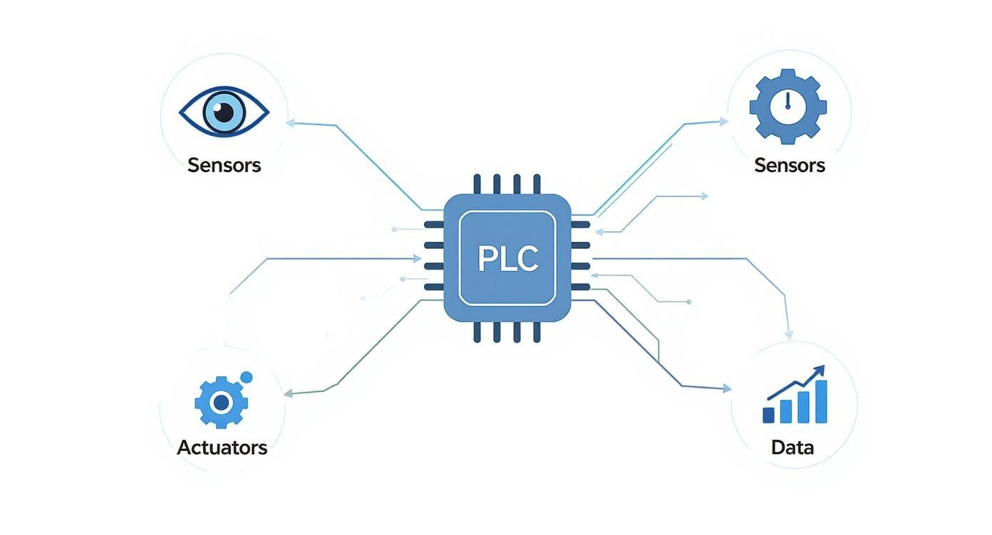
This whole system runs on a simple, continuous loop. Sensors act as the eyes and ears, gathering real-time data on things like temperature, pressure, or position. That information gets sent to the "brain"—usually a Programmable Logic Controller (PLC)—which makes split-second decisions based on its programming. From there, actuators like motors, valves, and grippers act as the "muscles," carrying out those commands with perfect accuracy.
The Driving Force Behind Modern Production
Let's be clear: adopting industrial controls automation isn't just a trend. It's a fundamental shift in how things get made. The main goal is to take human inconsistency out of the equation for repetitive tasks, paving the way for operational excellence.
This explosive growth is happening for one reason: automation delivers tangible, bottom-line results across every sector you can imagine, from car manufacturing to food and beverage packaging.
The real objective of industrial controls automation is simple: to create systems that are more efficient, safer, and more reliable than any manual process could ever be. It’s about achieving predictability in a complex environment.
Core Goals and Business Impact
At the end of the day, any decision to automate is tied directly to clear business goals. While the technology itself can get complex, the reasons for using it are refreshingly straightforward—it’s all about improving the bottom line and making operations more stable.
The table below breaks down the primary objectives that drive automation projects.
Objective
Description
Example Impact
Boost Efficiency & Throughput
Automating processes allows machinery to run faster and longer than humanly possible, often 24/7.
A packaging line that once produced 100 units per hour can now produce 300 with the same footprint.
Improve Product Quality
Automation eliminates human error from assembly and processing, ensuring every product meets exact specifications.
Defect rates in a CNC machining process drop from 3% to less than 0.1%, drastically reducing material waste.
Enhance Workplace Safety
Dangerous, repetitive, or strenuous tasks are handed over to machines, moving people out of harm's way.
Robotic welding cells eliminate worker exposure to harmful fumes, intense light, and high temperatures.
Reduce Operational Costs
Automation cuts long-term costs related to manual labor, rework, material waste, and downtime from errors.
A facility saves thousands per year by automating palletizing, reducing labor costs and injury-related expenses.
Ultimately, a well-implemented automation system is what allows a manufacturer to truly compete. It provides the tools needed to produce high-quality goods quickly, safely, and cost-effectively, which is the name of the game in today's global market.
The Building Blocks of a Control System
At its heart, an industrial control system is a lot like the human body. It has distinct parts that all work in harmony to pull off some pretty complex tasks. To really get a handle on industrial controls automation, you first need to know the core components—the actual hardware that senses what's happening, makes decisions, and then acts with incredible precision.
Picture a modern bottling plant. You’ve got thousands of bottles zipping down a conveyor, getting filled, capped, and labeled, all without a single person laying hands on them. This high-speed choreography is only possible because every piece of the automation puzzle knows exactly what it's supposed to do and when.
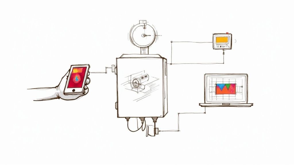
This diagram shows how the system's "brain" connects to its "senses" and "muscles."
As you can see, the PLC is the central hub. It's constantly crunching data from sensors to tell actuators what to do, creating a non-stop feedback loop that keeps everything running smoothly.
The Senses of the System: Input Devices
Every automated action has to start with information. Input devices, which are mostly sensors, act as the "senses" of the machine. Their job is to detect what’s going on in the real world and translate those physical conditions into electrical signals the control system can understand.
You'll find all kinds of input devices on a factory floor:
Proximity Sensors: These guys detect if an object is present without actually touching it. Back in our bottling plant, a proximity sensor confirms a bottle is perfectly positioned before the filling nozzle even thinks about activating.
Photoelectric Sensors: Using a beam of light, these can spot objects, check for colors, or even read marks. One might be used to verify a cap is properly twisted onto a bottle before it gets sent down the line.
Temperature and Pressure Sensors: Absolutely vital for process control. In a pasteurization line, these sensors make sure the product hits and holds a specific temperature for just the right amount of time.
Level Sensors: These measure how much liquid or material is in a tank or silo, telling a pump when it's time to kick on or shut off.
Without accurate and reliable data from these devices, the whole system would be flying blind.
The Brain of the Operation: Controllers
If sensors are the senses, then the controller is definitely the brain. This is where all the logic lives. The controller grabs all the incoming signals from the input devices, runs them through its programmed instructions, and then fires off commands to the output devices.
The workhorse controller in most manufacturing is the Programmable Logic Controller (PLC). Think of a PLC as a super-tough industrial computer built to survive the heat, dust, and vibration of a factory. It runs its program in a continuous, lightning-fast loop, making it incredibly reliable for machine control. Everything from the conveyor speed to the exact fill volume is dictated by the PLC's logic. Our internal guide takes a closer look at proper industrial control panel design, where these critical brains are housed.
The Voice and Eyes: The Human-Machine Interface
Even though a system is automated, you still need a human in the loop. The Human-Machine Interface (HMI) is the operator's window into the whole process. It’s usually a touchscreen panel that shows real-time data, alarms, and production status in an easy-to-read graphical format.
An HMI translates complex machine data into actionable information. It allows an operator to monitor the process, adjust settings like production speed, and troubleshoot issues without needing to understand the underlying PLC code.
From the HMI in our bottling plant, an operator could see how many bottles have been filled, get an alert if a capper jams, or switch the entire line over to run a different bottle size with just a few taps.
The Muscles of the Machine: Output Devices
Okay, so a decision has been made. Now what? Something has to physically happen. That's where output devices, or actuators, come in. They are the "muscles" of the system, taking commands from the PLC and turning electrical energy into real-world motion.
A few key output devices include:
Electric Motors: The movers and shakers that power conveyors, pumps, and fans.
Valves: Solenoid valves open and close to control the flow of liquids or gases—like the one dispensing soda into each bottle.
Actuators: These are typically pneumatic or hydraulic cylinders that push, pull, lift, or clamp things. An actuator might be what presses the label onto a finished bottle.
Relays and Contactors: These are essentially heavy-duty switches. They take a small signal from the PLC and use it to turn on and off much bigger equipment, like high-power motors.
Tying all of this together is the system's communication layer. Having a robust network infrastructure is non-negotiable; it's what ensures all these components can talk to each other without a hitch. Together, these building blocks create a cohesive system where every part knows its job, turning simple inputs into complex, high-speed production.
Understanding Control System Architectures
Knowing the individual parts of a control system is one thing. Understanding how they work together as a team is where the real magic happens. The way you organize those parts is the system's architecture, and picking the right one is like setting a formation for a football team—it all comes down to the scale and complexity of the game you’re playing.
You wouldn't use a single, localized controller to manage a sprawling chemical plant, just like you wouldn’t have one quarterback try to run an entire league. The architecture determines how data flows, where decisions get made, and how resilient the whole operation is when things go wrong.
Getting this right is more critical than ever. The industrial automation control market is on track to hit around USD 160 billion by 2029, driven by a global push for smarter, more efficient systems. You can dig into the numbers and trends in this detailed industry analysis from Technavio.
The PLC-Based Approach: Centralized Control
The most direct and common setup is centralized control, usually built around a single Programmable Logic Controller (PLC). Think of it as a "one-machine, one-brain" system. It's the go-to choice for self-contained, discrete manufacturing tasks where everything is happening in one spot.
A few classic examples include:
A single packaging machine that forms, fills, and seals boxes in sequence.
A CNC milling machine laser-focused on executing a specific cutting program.
An automated welding robot on an assembly line, repeating the same welds all day.
In this setup, one PLC is the undisputed boss. It takes in all the sensor data, runs the logic, and fires off all the commands. It’s simple, cost-effective for smaller jobs, and a lot easier to troubleshoot because you know exactly where to look.
Centralized control is the workhorse of machine-level automation. It excels at high-speed, self-contained tasks where simplicity and responsiveness are paramount.
Distributed Control Systems (DCS) for Plant-Wide Processes
But what happens when your "machine" is an entire plant? When you need to control a whole process spread across a massive facility, a single brain just won't cut it. That's where a Distributed Control System (DCS) steps in.
Instead of one central controller, a DCS uses multiple controllers, or "brains," distributed throughout the plant. Each one is responsible for a specific part of the process.
Picture a large oil refinery. You have separate processes for cracking, distillation, and treatment, all happening at once but all needing to work in perfect harmony. A DCS puts a dedicated controller at each of these stages. These local controllers handle their own business while reporting back to a central supervisory system, making sure the entire plant operates like a single, well-oiled machine. This design is also incredibly reliable—if one controller goes down, the whole plant doesn't grind to a halt.
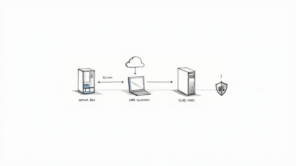
SCADA Systems: The Control Tower View
Now, let's zoom out even further. What if you need to monitor and control operations spread across different sites, or even an entire state? This is the domain of a Supervisory Control and Data Acquisition (SCADA) system.
Think of SCADA as the "air traffic control tower" for your industrial operations. It doesn't usually get bogged down in the millisecond-by-millisecond control logic; it leaves that to the PLCs and DCS controllers out in the field.
SCADA's job is to:
Gather data from all your remote equipment and sites.
Display that data on a central HMI for a human operator.
Let the operator issue high-level commands, like turning on a pump station fifty miles away.
SCADA is the backbone of our modern infrastructure—it runs everything from municipal water systems and electrical grids to oil and gas pipelines. It gives you the 30,000-foot view you need to manage assets that are miles apart.
To make sense of these options, it helps to see them side-by-side. Each architecture is tailored for a specific type of job.
Control System Architectures Compared
Architecture Type
Best For
Key Feature
Typical Scale
PLC-Based (Centralized)
Discrete, high-speed, single-machine tasks.
A single, powerful controller manages a localized process.
Machine or work cell.
DCS (Distributed)
Complex, continuous processes across a single, large facility.
Multiple interconnected controllers, providing high reliability and redundancy.
Entire plant or large processing facility.
SCADA (Supervisory)
Monitoring and controlling geographically dispersed assets and facilities.
Centralized monitoring and high-level control over remote sites.
Multiple sites, region, or entire pipeline.
Ultimately, the goal is to match the architecture to the operational reality. A simple PLC is perfect for a single machine, a DCS is built for a complex plant, and SCADA is designed to give you command over a sprawling territory.
The Critical Role of Safety and Compliance
In industrial automation, it’s easy to get caught up in the drive for more speed and higher efficiency. But the real bedrock of any great control system isn’t how fast it runs—it’s how safe it is. Without a rock-solid commitment to safety standards and compliance, even the most sophisticated automation setup is just an accident waiting to happen.
This isn't just about ticking boxes for an inspector. It’s about protecting your people, your multi-million dollar equipment, and your entire operation from preventable disasters. You wouldn’t build a high-rise without following the building code to the letter, right? The exact same logic applies to industrial control panels. These standards are the collected wisdom of decades of engineering, specifically designed to prevent fires, electrical shocks, and catastrophic failures.
The Gold Standard: UL 508A
When we talk about control panel safety in North America, one name stands above the rest: UL 508A. This is the official standard for the construction of Industrial Control Panels. If you see a panel with the UL 508A Listed mark, it means it was designed and built to meet the tough safety requirements set by Underwriters Laboratories.
A UL 508A listing is far more than a simple sticker. It’s a third-party guarantee that the panel's design, components, and assembly meet strict safety and performance criteria. It gives inspectors, insurers, and the people on the floor total peace of mind.
This certification covers just about every part of the panel build, ensuring the final product is both safe and dependable. The standard gets very specific about:
Component Selection: It mandates using UL-recognized components that have already been tested for their intended use.
Wiring and Sizing: It lays out the exact rules for wire sizing, insulation types, and termination methods to stop overheating and electrical faults before they start.
Enclosure Integrity: It ensures the panel’s cabinet is correctly rated for its environment, protecting the sensitive electronics inside from dust, water, and corrosion.
Spacing and Layout: UL 508A dictates precise clearances between components to prevent dangerous short circuits and electrical arcing.
Following these rules isn’t optional. It’s how you build systems that don’t just work well, but are fundamentally safe.
A Complete Safety Framework
While UL 508A is the cornerstone for the panel itself, it doesn't exist in a vacuum. It’s part of a much larger ecosystem of codes and standards that govern the entire electrical installation.
The big one is the National Electrical Code (NEC), also known as NFPA 70. The NEC sets the ground rules for the safe installation of all electrical equipment and wiring in the U.S., from how conduit is run to how everything is properly grounded.
Another key piece of the puzzle is NFPA 79, the Electrical Standard for Industrial Machinery. This standard zeroes in on the electrical equipment of machines, making sure their control systems are safe for operators to work with day in and day out. Of course, you also have to think about power quality inside the panel. For example, knowing how a harmonic filter for VFD can stabilize the system is a crucial part of a truly comprehensive and safe design.
Together, these standards create a layered defense. Sticking to them isn't about navigating red tape; it's about building strong, reliable industrial automation systems that protect your most important assets—your people and your ability to produce.
A Practical Roadmap for Your Automation Project
Taking an industrial controls project from a bright idea on a whiteboard to a humming, productive system on your floor demands a clear, disciplined approach. You wouldn't build a house without a blueprint, a solid crew, and a final inspection, and automation is no different.
The journey is best navigated with a phased roadmap. This breaks the whole complex undertaking down into manageable chunks, each with its own goals and deliverables. It’s the secret to minimizing those costly surprises and keeping the project on track, on time, and on budget.
Phase 1: The Design and Engineering Stage
This is where it all begins, and honestly, it's the most critical part of the whole process. Getting the design right now saves a world of headaches and expensive changes later.
It all starts by getting crystal clear on the project's goals. What problem are we really trying to solve? Are we chasing higher throughput, tighter quality control, or a safer environment for our team?
Once the "why" is established, we get into the "how" with a detailed Functional Specification document. Think of this as the system's biography—it describes exactly how the system needs to operate, from every sequence and alarm to every button an operator will push. From there, engineers can draft the electrical schematics, the true blueprints of the control panel that map out every last component, wire, and connection.
Phase 2: The Build and Assembly Stage
With approved designs in hand, the project jumps from the screen to the shop floor. This is where skilled technicians take over, fabricating, wiring, and assembling the control panel. It's a game of precision where attention to detail is everything.
The build process typically looks like this:
Enclosure Layout: Components like PLCs, power supplies, and terminal blocks are physically placed inside the enclosure, ensuring everything fits while allowing for proper airflow and wiring paths.
Component Mounting: All the hardware gets securely bolted to the panel’s backplane, following the schematics to the letter.
Wiring and Termination: Technicians meticulously run every wire—cutting, labeling, and landing each one on the correct terminal. Following UL 508A standards here isn't optional; it's essential for a safe, compliant panel.
A well-built control panel is more than just functional; it's a work of art. Neat wire management, crystal-clear labels, and precise assembly aren't just for show—they make the panel far easier to troubleshoot and maintain for years to come.
Before the panel ever leaves the shop, it goes through a rigorous quality check to make sure the physical build perfectly matches the drawings.
Phase 3: The Commissioning and Startup Stage
This is the moment of truth when the system comes to life. Commissioning is the methodical process of testing and proving that every single part of the system works together as intended.
It often kicks off with a Factory Acceptance Test (FAT) right at the panel builder’s shop. This gives you, the client, a chance to see the panel powered up and test its core logic before it even ships—a massive risk-reduction step.
Once the FAT is signed off, the panel heads to your facility for installation. The commissioning team then gets to work:
I/O Checkout: Every sensor, switch, motor, and valve is checked, verifying the signal path from the field device all the way back to the PLC and out again.
Functional Testing: The system is put through its paces, running every operational sequence to confirm it behaves exactly as laid out in the functional spec.
Safety System Verification: All emergency stops, light curtains, and other safety circuits are tested relentlessly to ensure they perform flawlessly when it matters most.
The project wraps up with a Site Acceptance Test (SAT), where you formally sign off that the system meets every requirement. Pulling off these phases smoothly requires real-world experience, which is why partnering with the right team is so important. For more on what to look for, you can explore our guide on choosing an industrial automation system integrator.
Measuring the True Value of Your Investment
Any industrial controls automation project is a serious capital expense. Once the dust settles, you've got to prove it was worth every penny, especially if you want to secure funding for the next big thing.
This isn't just about ticking a box. It's about turning a necessary expenditure into a powerful competitive advantage by showing clear financial and operational wins. The trick is to measure what actually matters and translate those shop-floor improvements into the language everyone in the C-suite understands: money.
Beyond the Price Tag: Calculating True ROI
The most straightforward way to justify the project is to calculate the Return on Investment (ROI). But a common mistake is only comparing the upfront cost to direct labor savings. A real ROI calculation for automation goes much deeper, accounting for a whole range of benefits that hit the bottom line.
To build a compelling business case, you need to track the specific Key Performance Indicators (KPIs) that your new automation system directly impacts. This hard data moves the conversation away from "cost" and firmly into "investment" territory.
Here are the big ones to watch:
Increased Throughput: How many more widgets are you making per hour or per shift? It's the cleanest measure of a productivity boost.
Reduced Material Waste: Precision automation means fewer mistakes and less scrap. Tracking this reduction is a direct line to cost savings.
Decreased Downtime: How much less time are you spending on unplanned shutdowns? Every minute a line is down, money is walking out the door.
Improved Quality: Look at the drop in product rejection rates or customer returns. Better quality means fewer costly recalls and warranty headaches.
The Gold Standard: Overall Equipment Effectiveness (OEE)
If you want one single metric that tells the whole story, it's Overall Equipment Effectiveness (OEE). OEE is the gold standard for measuring manufacturing productivity because it rolls three critical factors into one clean score, giving you a powerful, holistic view of your operation's health.
OEE essentially measures how much of your planned production time is genuinely productive. A world-class OEE score is 85% or higher, but honestly, many facilities start much lower. That just means there's a massive opportunity for improvement with automation.
OEE is calculated by multiplying three core components:
Availability: This tracks any event that stops planned production—think equipment failures or material shortages. An Availability score of 100% means the process ran without any stop-loss during its planned time.
Performance: This accounts for anything that makes the process run slower than its theoretical top speed, like micro-stops or reduced-speed cycles. A 100% Performance score means you're running as fast as theoretically possible.
Quality: This one's simple—it tracks defective parts, including those that need to be reworked. A 100% Quality score means you're producing nothing but good parts.
By tracking your OEE score before and after the automation project goes live, you create an undeniable, data-driven narrative of success. It transforms the value of industrial controls from an abstract idea into a concrete, measurable business achievement.
Got Questions About Industrial Controls? We’ve Got Answers.
Diving into industrial controls automation can feel like learning a new language. You’ve got the big picture, but the devil is always in the details. Let's tackle some of the most common questions that come up when people are moving from theory to the factory floor.
Core Technology and Project Timelines
What’s the real difference between a PLC and a DCS?
It's a classic question. Think of it like this: a PLC (Programmable Logic Controller) is a highly specialized sprinter. It’s built for one primary job—controlling a specific machine or a small, self-contained process with lightning-fast reflexes and rock-solid reliability.
A DCS (Distributed Control System), on the other hand, is the plant’s quarterback. It’s designed to see the whole field, managing and coordinating large, sprawling, continuous processes. A DCS brings all the individual plays together into one unified, plant-wide strategy.
How long does an industrial automation project actually take?
That's the million-dollar question, and the honest answer is: it depends entirely on the scope. A straightforward control panel for a single machine? We could be looking at just a few weeks from design to commissioning.
But if you're talking about a full-scale system integration across your entire facility, you’re in for a longer haul. These projects can easily take many months, sometimes even over a year, once you factor in equipment lead times, custom software development, and the crucial design and engineering phase.
The bottom line: Project timelines are a direct reflection of complexity. Small, well-defined jobs are quick wins. Large, multi-system integrations are a marathon, not a sprint, requiring a detailed roadmap from day one.
Compliance and Modernization
Why is everyone so insistent on a UL-listed control panel?
It’s all about safety and accountability. A UL-listed control panel isn't just a fancy sticker; it's your proof that the panel has been built to meet rigorous safety standards tested by an objective third party, Underwriters Laboratories.
This certification is your ticket to passing inspections, satisfying insurance requirements, and protecting your people and equipment from fire and electrical hazards. In most places, it's not a "nice-to-have"—it's a non-negotiable requirement.
Can I actually put modern controls on my old machinery?
Absolutely, and it’s one of the smartest moves you can make. This is called a retrofit, and it's a super common and cost-effective way to modernize.
We see it all the time: a machine is mechanically sound—the "bones" are good—but the controls are from a different era. By swapping out the old relays and timers for modern PLCs, HMIs, and sensors, you get all the benefits of automation—better data, higher efficiency, improved safety—without the massive capital expense of buying a brand-new machine. The first step is always a deep-dive assessment of the existing equipment to build a solid game plan.
Turning these concepts into a reliable, high-performing system takes a partner who knows both the parts and the process inside and out. At E & I Sales, we deliver complete integration services, from custom UL control panel design to full system commissioning, making sure your project is built right, fully compliant, and ready to perform.
An industrial automation system integrator is the essential bridge between your collection of complex machinery and a smooth, cohesive operation. Think of them as the conductor of an industrial orchestra. They make sure every separate piece of equipment—from motors and sensors to software and HMIs—works together in perfect harmony to hit your production targets.
Your Partner in Manufacturing Modernization
So many modern facilities share the same headache: a plant full of high-performing machines that just don't talk to each other. You might have a cutting-edge filler from one vendor, a capper from another, and a palletizer from a third. Individually, they're great. But together? They create bottlenecks, inefficiencies, and huge operational blind spots because they operate in isolation.
This is exactly where an industrial automation system integrator comes in. Their whole job is to bridge those gaps. They design and implement a unified control system that makes the entire production line function as a single, intelligent unit. They aren't just selling you equipment; they are strategic partners who diagnose deep-seated problems, engineer real-world solutions, and see complex projects through from concept to commissioning.
To get a clearer picture, here’s a quick breakdown of what a system integrator really does.
The System Integrator Role At a Glance
Core Function
Typical Clients
Primary Benefits
Design, build, and deploy unified automation and control systems.
Integrate new equipment with existing legacy machinery.
OEMs & Equipment Packagers
Faster project timelines, guaranteed system performance.
Provide specialized skills in PLC/SCADA, robotics, and electrical engineering.
Facilities with limited in-house expertise.
Access to expert knowledge without hiring full-time staff.
This table just scratches the surface, but it highlights how integrators solve tangible business problems, not just technical ones.
From Disconnected Parts to a Unified Whole
The real value of an integrator is their ability to turn operational chaos into a streamlined, data-driven process. They blend electrical engineering, software development, and—most importantly—deep industry knowledge to make your factory smarter, faster, and more reliable.
A truly qualified partner takes full ownership of making all these disparate systems play nicely together. Their work is a direct answer to the most common pain points for plant managers, engineers, and OEMs.
What does this look like in practice? An integration project usually focuses on a few key goals:
Boosting Throughput: By syncing up machine speeds and killing bottlenecks, integrators help you get more product out the door with the exact same assets.
Slashing Unplanned Downtime: A unified system gives you far better diagnostics, letting maintenance crews find and fix issues in minutes, not hours.
Improving Product Quality: Real automation means consistent, repeatable processes. This drastically cuts down on human error and keeps your product within spec.
Enhancing Safety: Properly integrated systems are built with safety from the ground up, incorporating features like light curtains and E-stops that actually protect your people.
An integrator's job is to see the entire factory floor not as a series of individual tasks, but as one interconnected ecosystem. Their expertise lies in creating the 'nervous system' that allows every component to communicate and react in real-time.
The True Scope of an Integrator
At the end of the day, bringing in an industrial automation system integrator is an investment in operational excellence. They bring the highly specialized skills needed to handle everything from fabricating a UL-listed control panel to writing complex PLC and SCADA programs.
This guide will walk you through what these experts do, the services they offer, and how you can select the right partner to truly modernize your facility. By the time you're done, you’ll see why an integrator is an indispensable asset for any company that's serious about improving productivity and staying competitive.
So, What Does a Turnkey System Integrator Actually Do?
If a system integrator is the "conductor" of your factory's orchestra, what are they actually doing with the baton? Their role goes way beyond just drawing up plans. A true turnkey partner gets their hands dirty, providing a whole range of services to take a concept and turn it into a living, breathing, reliable system.
Think of them as the master electrician and programmer for your plant's central nervous system. They don't just sketch the blueprints; they're the ones sourcing the right components, running the "nerves" and "muscles," and making absolutely sure every signal gets where it needs to go—safely and without fail.
It's no surprise that demand for these skills is exploding. The system integration market hit $46.469 billion in 2021 and is projected to reach $57.49 billion by 2025. That growth, tracked by firms like Cognitive Market Research, is coming from every corner of industry, from energy production to CPG packaging.
Designing and Building UL-Listed Control Panels
The heart of any modern automated system is the industrial control panel. This isn't just a generic grey box full of wires. It’s the physical brain of the entire operation, housing the sensitive PLCs, drives, and relays that make everything happen. A top-tier integrator doesn't just design these panels—they build them from scratch in their own UL-listed panel shop.
Why is that UL sticker so critical?
It’s a Safety Guarantee: A UL 508A certification is proof that the panel was built to strict, third-party safety standards. It’s about protecting your people and your multi-million dollar equipment.
It's Your Ticket Past Inspection: UL-listed panels are designed to meet the National Electrical Code (NEC) and other local rules. This is non-negotiable for passing inspections and keeping your insurance provider happy.
It’s Built to Last: The UL standard is incredibly detailed, covering everything from how far apart components must be to the right gauge of wire for a specific load. The result is a rock-solid panel that can handle the heat, vibration, and dust of a real industrial floor.
Frankly, a control panel without a UL listing is a massive liability. When an integrator delivers a UL-listed panel, they’re giving you a product that’s certified safe, compliant, and built for the long haul.
A UL-listed control panel is your assurance that the system's core has been professionally engineered and fabricated to the industry's highest safety and quality benchmarks. It’s a non-negotiable mark of a credible integrator.
Mastering PLC and SCADA Integration
Once the physical hardware is in place, the integrator brings it all to life with code. This is where Programmable Logic Controllers (PLCs) and Supervisory Control and Data Acquisition (SCADA) systems enter the picture.
If the control panel is the brain, think of PLCs as the reflexes. These are small, rugged computers built to survive on the factory floor. The integrator writes the custom logic that tells a motor when to spin up, a valve when to open, or a robotic arm precisely where to move—all in milliseconds.
SCADA software is the "big picture" view—the consciousness of the whole operation. It pulls data from all the individual PLCs and puts it onto a single, intuitive dashboard, often called a Human-Machine Interface (HMI).
Together, they create a complete nervous system for your plant.
Sensors (the nerves) grab data from the equipment.
PLCs (the spinal cord) process the data instantly and fire off commands.
SCADA/HMI (the conscious mind) gives your operators a bird's-eye view, letting them monitor performance and make smart decisions.
An experienced integrator is an expert at weaving these elements together seamlessly. They give you the power to see and control your entire production line from one screen.
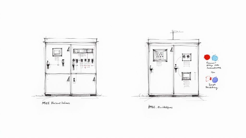
Engineering Motor Control and Power Systems
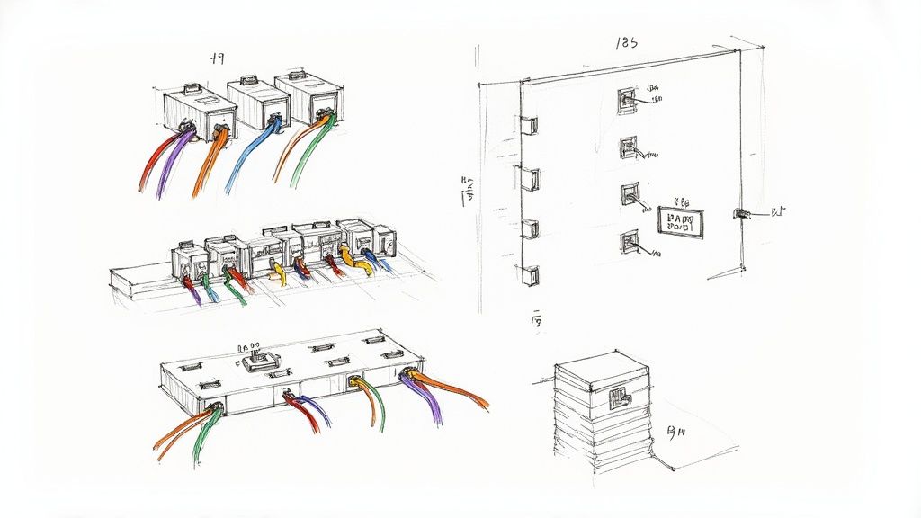
Motors are the muscles of your operation. They drive the pumps, fans, conveyors, and mixers that do the actual work. A system integrator is responsible for designing and building the Motor Control Centers (MCCs) that safely power and control all of it.
This is a lot more than just hooking up wires. The job includes:
Calculating Electrical Loads: Making sure the power system can handle the demand from every motor without tripping breakers or causing brownouts.
Integrating VFDs: Installing Variable Frequency Drives (VFDs) to fine-tune motor speed. This not only gives you better process control but can also slash your energy bills.
Designing Safety Interlocks: Wiring the motor controls directly into the plant’s safety systems, like e-stops, to protect your team.
Getting the motor control and power distribution right is fundamental to keeping your plant running efficiently and reliably for years to come.
Final Commissioning and System Handover
The final, and arguably most important, step is commissioning. This is where theory meets reality. The integrator's team comes on-site to fire up the entire system and put it through its paces in your actual facility. It's the full-dress rehearsal before opening night.
During commissioning, the integration team is busy:
Verifying every single wire is landed in the right place.
Testing every line of PLC code under real conditions.
Calibrating sensors and instruments for pinpoint accuracy.
Simulating every possible failure to ensure safety systems work perfectly.
Training your operators and maintenance crew until they're confident running the new system.
This exhaustive process ensures that when you finally flip the switch to "go-live," the system just works. A true turnkey integrator doesn't just drop off a bunch of hardware and a binder; they deliver a fully tested, documented, and running solution that sets your team up for success.
Mapping the Automation Project Journey
Bringing an industrial automation project to life is so much more than just buying some new equipment. It’s a carefully managed journey from a high-level goal to a fully operational system that actually drives value. An experienced system integrator is your guide through this entire process, making sure every single step is handled with precision.
You can think of the project lifecycle in four distinct phases. Each stage builds on the one before it, turning a simple idea into a real-world competitive advantage. Understanding this flow shows you why an integrator is a strategic partner, not just another vendor.
Phase 1: Discovery and Design
It all starts with a deep dive into your operation. In the Discovery and Design phase, the integrator acts more like a consultant than an engineer. The main goal here is to get a rock-solid understanding of your unique challenges, your business goals, and the specific pain points you're trying to solve.
They'll be asking the tough questions to truly define the project's scope:
What's the exact inefficiency we're tackling here?
How will we measure success? What are the key performance indicators (KPIs)?
How does this new system need to play with the legacy equipment already on the floor?
This back-and-forth results in a comprehensive Functional Specification document. This isn't a simple quote; it's the master blueprint. It lays out exactly how the system will work, what it will do, and how everyone will know it’s a success, preventing costly headaches and scope creep down the road.
Phase 2: Engineering and Development
With a clear roadmap in hand, the project moves into the Engineering and Development phase. This is where the big ideas get translated into technical reality. The integrator’s electrical engineers and software developers roll up their sleeves and turn the functional spec into detailed designs.
This is where the heavy lifting happens:
Creating Electrical Schematics: These are the detailed drawings for control panels, power distribution, and all the field wiring. They're the foundation of the physical build.
Developing PLC and HMI Logic: Programmers get to work writing the custom code that will actually run the machines and creating the intuitive screens your operators will use every day.
Procuring Hardware: Key components with long lead times—like PLCs, drives, and specialized sensors—are ordered early to keep the project timeline on track.
This phase is the technical heart of the project. Meticulous engineering here ensures the final system is not only functional but also safe, compliant, and maintainable for years to come.
Phase 3: Implementation and Installation
Now, the project jumps off the screen and into the real world. During the Implementation and Installation phase, the system gets built, assembled, and ready for deployment. For any quality integrator, a huge chunk of this work happens off-site in their own shop.
UL-listed control panels are built in a controlled environment, which means higher quality and strict adherence to safety standards. The core logic is often tested on simulators long before it hits your floor—a smart move that can slash on-site startup time by as much as 30%. Once the pre-built components arrive, the on-site work of running conduit, pulling wire, and mounting hardware can begin with minimal disruption to your daily operations.
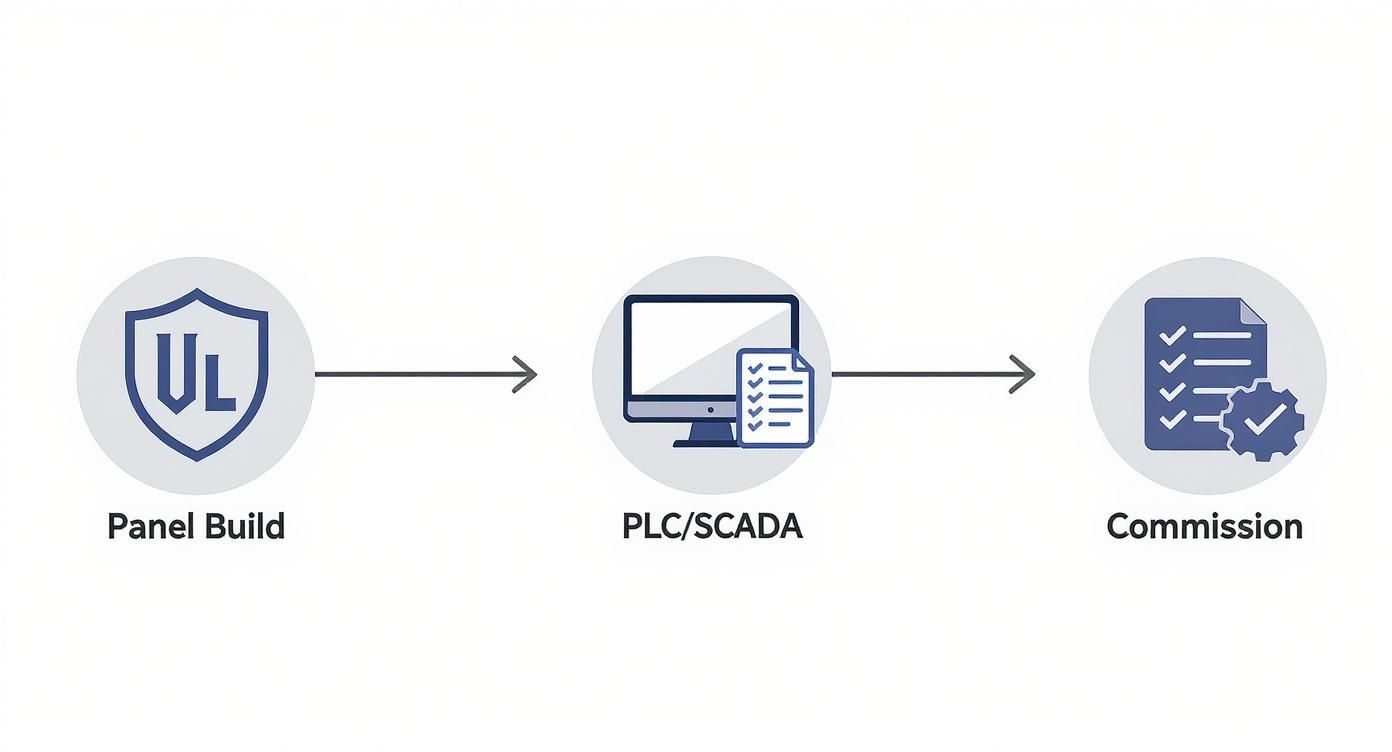
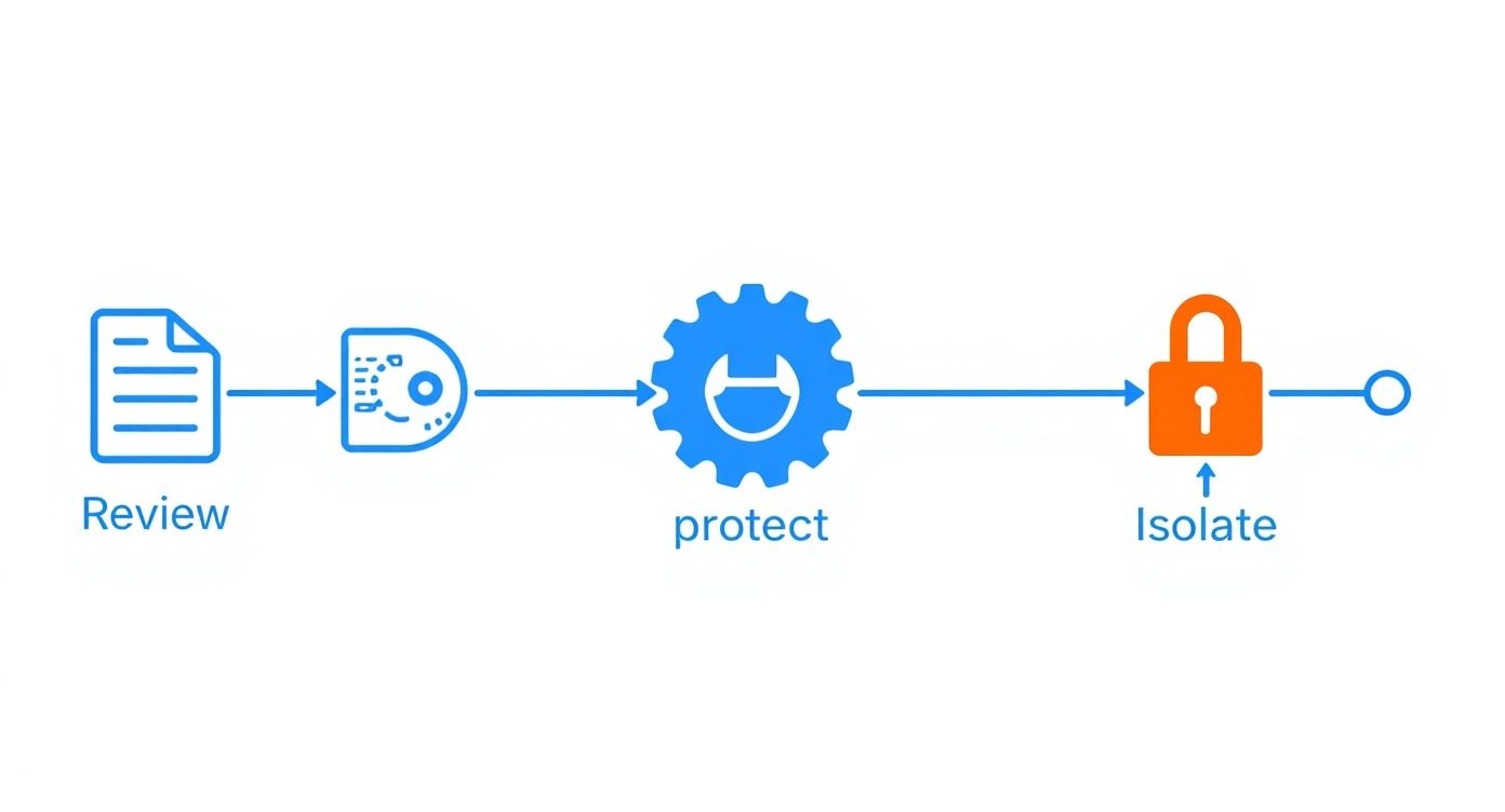
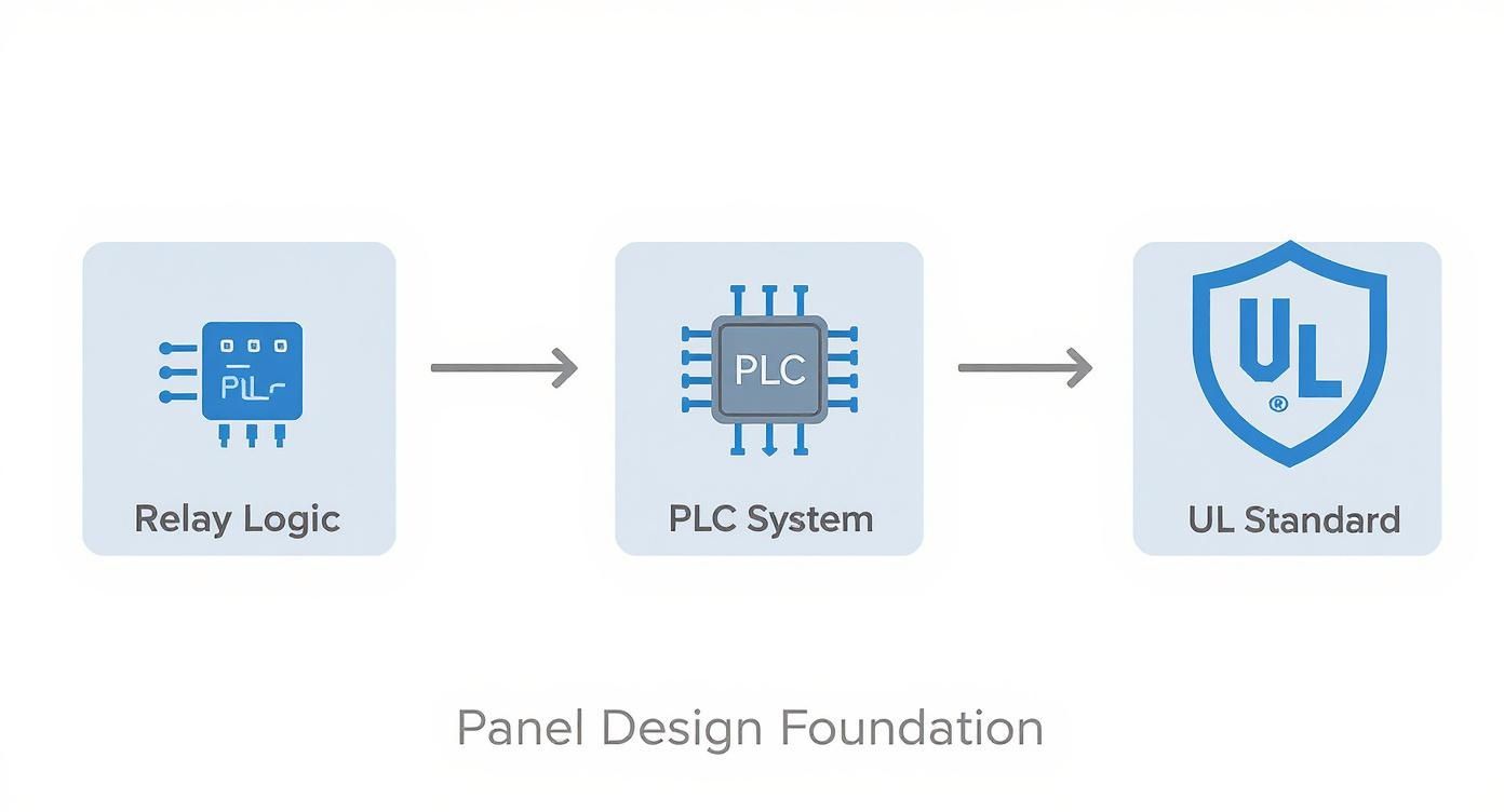
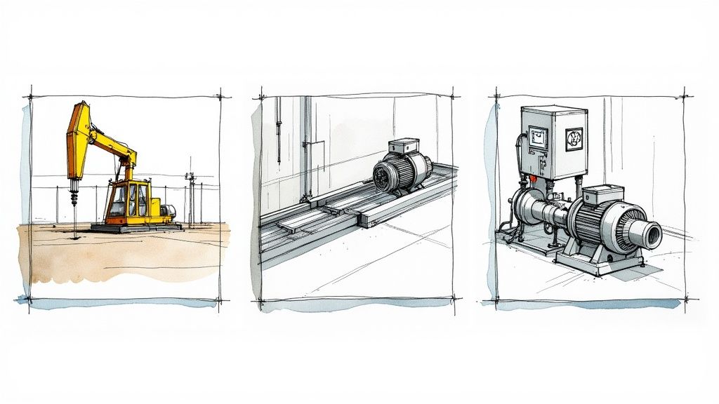
This visual shows how an integrator’s core services flow from the panel build to PLC/SCADA integration and final commissioning.
This structured workflow really shows how each step logically builds on the last, ensuring a smooth handoff from building the hardware to deploying the software and validating the whole system.
Phase 4: Commissioning and Support
This is the moment of truth. In the final Commissioning and Support phase, the system comes to life. The integrator’s field engineers are on-site to power everything up, test every function in a real-world setting, and fine-tune its performance. They methodically check every single input and output—from the tiniest sensor to the main motor starter—to make sure it works exactly as designed.
This process ends with the official "go-live," but the partnership doesn't stop there. A good integrator provides thorough documentation, hands-on training for your operators and maintenance crew, and a clear plan for ongoing support. After all, guiding a project to completion requires strong management. You can explore the core IT project manager's responsibilities to see how those same principles ensure a project’s long-term success. This final handover ensures your team is ready to take ownership and run the new system with confidence from day one.
Getting into the Weeds: Technical Designs and Compliance
To really get what an industrial automation system integrator brings to the table, it helps to peek under the hood at the technical backbone of a modern automated system. You don’t need an engineering degree, but understanding the basic architecture shows you how a bunch of disconnected machines becomes one smart, cohesive operation.
It’s all about creating a conversation between different pieces of hardware and software. Every component has a job, and the integrator is the translator making sure they all speak the same language. This builds a powerful feedback loop where machines can report their status, take new orders, and adapt on the fly.
The Basic Architecture of an Automated System
The best way to think about the system is a pyramid. At the bottom, you have the devices actually touching your product. As you move up, you get to the software that gives you the 30,000-foot view of the entire plant.
Here’s a quick tour of the key layers, from the ground up:
Field Level: This is where the action happens. It’s home to sensors (like photo-eyes or temperature probes) and actuators (motors, valves, and solenoids). The sensors are the system's eyes and ears, and the actuators are its hands and feet.
Control Level: Here you’ll find the Programmable Logic Controller (PLC). This is the local brain, taking signals from the sensors and using its programming to tell the actuators what to do. It’s making the split-second decisions that keep everything moving.
Supervisory Level: This is the command center, featuring Human-Machine Interfaces (HMIs) and SCADA systems. An HMI is the touchscreen an operator uses to interact with one machine, while SCADA gives you a central dashboard to monitor and control the whole facility.
This layered setup is the blueprint for modern manufacturing. A good integrator architects this entire data flow, making sure a single signal from a tiny sensor can eventually inform a huge business decision about plant efficiency.
It’s no surprise that the pros who can design these systems are in high demand. The market hit around USD 23.61 billion recently and is on track to reach USD 34.17 billion by 2035, according to Market Research Future. That growth is fueled by one thing: the relentless need for greater efficiency.
The Unbreakable Rules of Compliance
While a clever technical design is fantastic, it’s all built on a foundation of safety and compliance that you simply cannot ignore. These aren't just "best practices"—they're rigid codes that guarantee the system is safe, reliable, and won't cause problems down the road. For any integrator worth their salt, compliance is baked in from the very first drawing.
In North America, two of the big ones are UL 508A and the National Electrical Code (NEC).
UL 508A: This is the gold standard for Industrial Control Panels. A UL-certified shop has proven they can build panels that meet intense safety requirements for everything from component choice to wiring methods. That UL sticker is your proof of quality and a must-have to pass inspections.
National Electrical Code (NEC): The NEC is the rulebook for safe electrical installations in the U.S. An integrator has to know it inside and out to make sure every wire, conduit, and connection is done right, preventing fires and other electrical hazards.
Following these codes is about so much more than just ticking a box. It's about protecting your people, your equipment, and your investment. An experienced integrator designs every piece of the project—from the schematics to the final wire pull—with these standards front and center. For a closer look at what goes into it, check out our guide on industrial control panel design. This obsession with compliance is what separates the real pros from the rest.
How Integration Delivers Real-World ROI
Sure, technical drawings and project plans are important. But the real test of any automation project is its impact on your bottom line. A good industrial automation system integrator delivers more than just a functioning system; they deliver real business results you can see in higher throughput, fewer product defects, and a dramatic drop in unplanned downtime.
Let's move past the theory and look at what this means on the ground. The following examples show how a smart integration partner can turn a nagging operational headache into a serious competitive advantage. These aren't just stories about technical upgrades—they're stories about business transformation.
Case Study: OEM Control System Standardization
A mid-sized Original Equipment Manufacturer (OEM) that builds packaging machinery was hitting a wall. Each machine they built had a slightly different control system, often customized for a specific client. This was creating a logistical nightmare, slowing down production and making field service a slow, painful process.
They needed to standardize their control architecture across their entire product line. To get it done right, they brought in an experienced system integrator.
The solution broke down into a few key moves:
Platform Selection: First, the integrator guided the OEM in choosing a single, scalable PLC and HMI platform that could be adapted for every machine model.
Modular Code Development: Next, they built a library of modular, reusable PLC code. Instead of programming from scratch every time, engineers could now pull from proven code blocks, which cut development time by over 40%.
UL-Listed Panel Design: Finally, they engineered a standardized, UL-listed control panel. This ensured consistency, simplified manufacturing, and guaranteed safety and compliance for every single unit that shipped.
By teaming up with an integrator, the OEM completely changed how they operated. They now deploy new machines faster, give customers better support, and keep a much smaller, more manageable inventory of spare parts. It was a strategic shift that directly fueled their profitability and strengthened their position in the market.
Case Study: Manufacturing Plant Downtime Reduction
A food and beverage plant was dealing with constant, unpredictable production stoppages. Their control systems were a mess—a patchwork of old equipment from different vendors that gave them zero central visibility. When a machine failed, maintenance crews were basically flying blind, often burning hours just trying to find the root of the problem.
The mission was clear: get real-time insight into the production line to slash unplanned downtime and boost their Overall Equipment Effectiveness (OEE). The plant partnered with an integrator to design and roll out a modern SCADA system.
The new SCADA system became the single source of truth for the entire plant. It pulled data from every machine, giving operators and managers an intuitive, real-time dashboard of the facility's health.
The results were immediate. With clear diagnostics and historical data at their fingertips, the maintenance team could pinpoint issues in minutes, not hours. This proactive approach led to a 20% reduction in unplanned downtime in just the first six months.
The added visibility also opened the door to new energy efficiency gains, a topic we dive into in our article on VFD energy savings. This push for smarter integration is happening globally. In fact, the International Federation of Robotics reported that Asia installed over 404,578 industrial robots in a single year, a 5% increase. This highlights the intense demand for integrated systems that boost productivity. You can find more market insights like this on Research Nester.
How to Pick the Right Automation Partner for Your Plant
Choosing an industrial automation system integrator is probably the single most important decision you'll make for any automation project. Get it right, and you're set up for long-term reliability and efficiency. Get it wrong, and you're in for a world of headaches. This choice goes way beyond just picking the lowest bid; it's about finding a true partner who gets what you're trying to accomplish.
A good selection process takes the guesswork out of the equation. It starts with putting together a detailed Request for Proposal (RFP). This document isn't just a formality—it's your chance to clearly lay out the project scope, technical specs, and what success looks like for your business. A solid RFP forces potential integrators to show they've actually listened and have the chops to deliver.
What to Look for in a Top-Tier Integrator
As the proposals start coming in, you need to know what separates the great from the good. A strong partner will shine across the board, showing they have both the technical skills and the business sense to see your project through.
Here are a few things that should be non-negotiable:
Real Technical Expertise: Do they have their own, in-house UL-certified panel shop? This is a huge tell. It shows a deep commitment to quality and safety standards, not just outsourcing the critical stuff. You also need to confirm their experience with the specific PLC, SCADA, and motor control brands you already have on your floor.
Proven Industry Experience: An integrator who's already tackled problems in your world—whether it's high-speed packaging, municipal water treatment, or food and beverage—will hit the ground running. They already know the unique challenges, compliance hoops, and operational pressures you face every day.
A Clear Project Management Playbook: How do they handle the inevitable scope change? What does their communication rhythm look like? You want a partner with a documented process who keeps you in the loop from kickoff to commissioning, not one who goes dark for weeks at a time.
The whole reason you're even considering automation is to gain a competitive edge through better efficiency, lower costs, and smarter operations. For a broader look at what's possible, it's worth exploring the benefits of automation in business.
Asking the Questions That Matter
Once you've narrowed it down to a shortlist, it's time to get them in a room (or on a call) and dig deeper. This is your chance to move past the sales pitch and see how they really operate.
Here are a few questions that cut right to the chase:
"Walk me through your commissioning process and what your support looks like after you're gone." This tells you everything about their commitment to a smooth handover. A great partner doesn't just flip a switch and leave; they provide thorough training and have a clear plan for long-term support.
"Tell me about a project where you had to tie new equipment into a client's ancient legacy system." This is where the rubber meets the road. Almost every plant is a mix of old and new, and you need an integrator who has real-world experience making it all play nice together.
"How do you handle documentation, from electrical schematics to the PLC code?" Clear, well-commented documentation is gold for your maintenance team. If they can't easily understand how the system works long after the integrator has left, you're setting them up for failure.
System Integrator Evaluation Checklist
To make this process more concrete, use a simple scorecard. It helps you compare your top candidates side-by-side and keep the decision objective.
Evaluation Criterion
Integrator A
Integrator B
Integrator C
In-House UL-508A Panel Shop
Relevant Industry Case Studies
Experience with Your Control Platforms
Clear Project Management Process
In-House Commissioning Team
Post-Project Support Plan
Quality of Documentation
This simple tool ensures you're weighing each potential partner against the same critical factors, leading to a much more confident decision.
At the end of the day, picking the right industrial automation system integrator is about finding a team you can trust to wrestle with complexity and deliver a rock-solid solution. By starting with a structured RFP and asking tough, insightful questions, you can confidently find a partner that aligns with both your technical needs and your business goals. When you're ready to find a team that pairs UL-certified fabrication with true turnkey support, digging into their specific https://eandisales.com/products/system-integration/ is the right next move.
Common Questions About System Integration
Diving into an automation project always brings up a few big, practical questions. Getting straight answers is the only way to move forward with any real confidence. Let's tackle some of the most common things we hear about cost, timelines, and dealing with older equipment.
What’s the Real Cost and Timeline?
There’s no "one-size-fits-all" answer here, which is why a trustworthy integrator will never give you a price over the phone. A simple PLC upgrade on a single machine might wrap up in a few weeks for a few thousand dollars. A full-blown plant integration, on the other hand, could be a multi-million dollar investment that spans a year or more.
A real partner starts by digging deep to understand exactly what you need to accomplish—what we call the discovery phase. Only then can they build a detailed proposal that breaks down the costs and lays out a project schedule that actually makes sense.
You'll always see costs coming from four main areas:
Hardware: The physical gear, like PLCs, drives, sensors, and control panels.
Software Development: The hours spent programming your PLC, SCADA, and HMI systems to do the work.
Engineering: The time it takes for design, creating schematics, and managing the project from start to finish.
Commissioning: The on-site hours for installation, testing everything, and training your team.
How Do You Integrate New Systems with Our Old Equipment?
This is where an experienced integrator really earns their keep. For most plant managers, the last thing they want is a massive "rip and replace" project. The goal is always to bring in modern capabilities without throwing out perfectly good, reliable machinery.
It all starts with a detailed audit of your existing equipment. From there, we map out a phased integration plan designed to cause as little disruption to your production as possible.
We have a few proven strategies for bridging that technology gap. Sometimes it's a communication gateway that acts like a translator between old and new protocols. Other times, we retrofit older machines with modern controllers and sensors. This way, you keep the value of your legacy assets while adding powerful new tools for data collection and control.
The real art of integration is making new and old systems talk to each other flawlessly. It protects your original investment while giving you all the benefits of modern automation.
What Kind of Support Can We Expect After Go-Live?
A project isn’t a success until it's running smoothly long after we've left the building. A quality integrator shifts from being a builder to a long-term support partner. The handover should be seamless, leaving your team feeling confident and fully in control of the new system.
That means you get comprehensive documentation—electrical schematics, operational manuals, and well-commented PLC code. It also includes hands-on training for your operators and maintenance staff right on your floor.
Most importantly, there should be a clear Service Level Agreement (SLA) outlining what ongoing support looks like. This could include remote monitoring, on-call assistance for troubleshooting, and preventative maintenance plans to keep you running at peak performance for years to come.
Ready to modernize your operations with a partner who delivers from concept through commissioning? E & I Sales combines decades of motor expertise with UL-certified control packaging and true turnkey system integration. Learn how we can solve your toughest automation challenges at https://eandisales.com.
A truly proactive motor control center maintenance program is built on a foundation of rigorous safety prep, not last-minute fixes. It’s about creating a bulletproof plan before you ever open a cabinet—establishing clear Lockout/Tagout procedures, gearing up with the right arc flash PPE, and digging into the technical docs. This upfront work ensures every action you take is safe, informed, and actually effective.
Establishing Your MCC Maintenance Foundation
Before a single tool touches a motor control center, the real work has already begun. Laying the groundwork for safety and efficiency is everything. I’ve seen too many teams jump right in, and it's a dangerous mistake that leads to accidents, fried equipment, and painful stretches of downtime.
Effective maintenance isn't just about turning wrenches; it's about building a systematic, safety-first culture around these critical assets.
This foundation really comes down to three things: completely isolating energy sources, protecting your people, and knowing the equipment's history inside and out. If you drop the ball on any one of these, you're introducing massive risk and turning a controlled procedure into a high-stakes gamble.
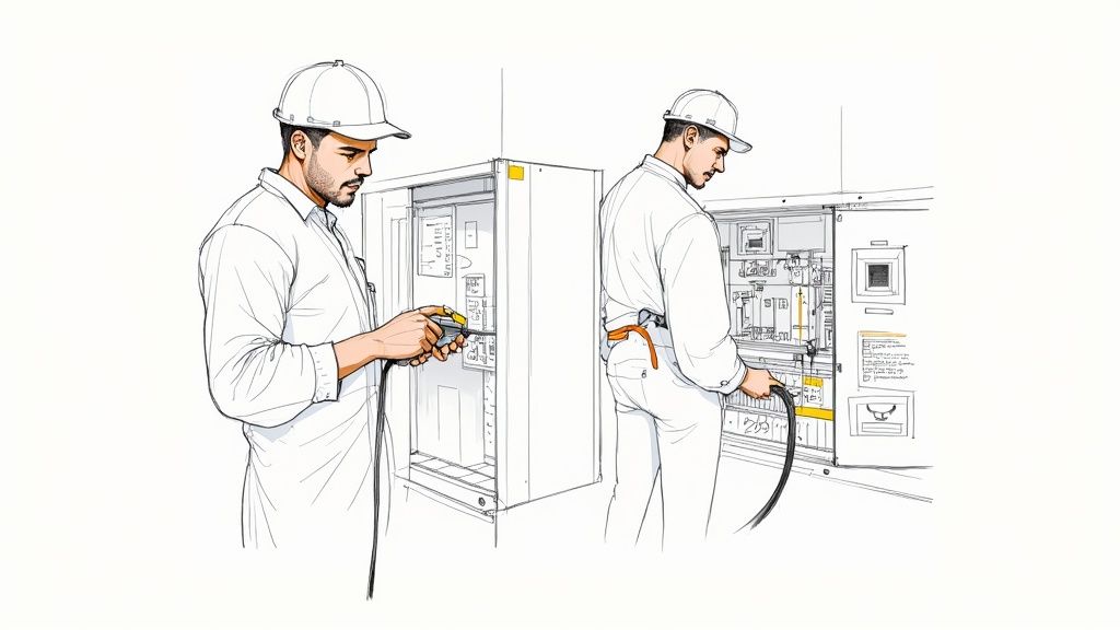
Fortifying Safety with Lockout/Tagout Protocols
A rock-solid Lockout/Tagout (LOTO) procedure isn't just a suggestion—it's the absolute cornerstone of safe MCC maintenance. This is way more than just flipping a switch. It's a documented, verifiable process that guarantees all energy sources are dead and locked out before anyone gets started. For complex MCCs, that often means tracking down multiple power feeds, sneaky control circuits, and even the stored energy lurking in capacitors.
Your LOTO program has to be specific to each piece of gear. A generic, one-size-fits-all checklist just doesn't cut it. Here’s what a proper procedure looks like in the real world:
Detailed Shutdown Steps: It clearly maps out the sequence for de-energizing, isolating, and securing every single energy source. No ambiguity.
Verification of Isolation: This is the big one. A qualified person must test for the absence of voltage with a properly rated multimeter before work begins. It’s a non-negotiable step.
Clear Lock and Tag Application: It defines exactly who is authorized to apply locks and tags, making sure every worker involved has their own personal lock on the isolation point.
Shift Change Procedures: It lays out how LOTO is handed off between shifts to maintain a continuous bubble of safety.
The single most critical moment in any electrical maintenance task is proving the absence of voltage. Never, ever assume a circuit is dead. Always test, verify, and then test again before you proceed.
Selecting the Right Personal Protective Equipment
Personal Protective Equipment (PPE) is your last line of defense against the brutal physics of an arc flash. Let's be clear: standard work gloves and a hard hat are not going to cut it when you're working on or near an energized MCC. The level of PPE you need is determined by an arc flash risk assessment, which calculates the potential incident energy at that specific spot.
This risk is broken down into PPE Categories by NFPA 70E, ranging from 1 to 4. For instance, getting into a 480V MCC might call for Category 2 PPE. That typically means an arc-rated shirt and pants, an arc flash suit hood, and voltage-rated gloves with leather protectors. Always look for the arc flash label on the MCC panel—it will tell you the incident energy level and the required PPE category for working safely.
Gathering and Reviewing Essential Documentation
Walking into a maintenance job blind is a recipe for disaster. Before you even think about starting, your team needs to gather and review all the relevant documentation. This paperwork is your roadmap. It helps technicians understand the system's design, its operational history, and all its little quirks. If you're new to the equipment, just understanding what a motor control center is through some foundational reading can provide crucial context.
Here are the key documents you need in hand:
One-Line Diagrams: These show the power flow through the MCC, identifying sources, feeders, and major components.
Schematics and Wiring Diagrams: These give you the nitty-gritty details on control circuits, interlocks, and how everything is connected.
Previous Maintenance Logs: This is gold. It offers insights into past problems, repairs, and recurring issues that can help guide your inspection.
Reviewing this documentation lets you plan the scope of work, spot potential challenges ahead of time, and make sure you have the right spare parts and tools ready to go.
Your Proactive MCC Inspection Schedule
A reliable motor control center doesn't just happen. It's the direct result of a smart, consistent inspection schedule. If you're still stuck in the old "fix-it-when-it-breaks" loop, you're falling behind. In today's highly automated plants, unexpected downtime can easily eat up 20-30% of your production losses. That’s a massive, and frankly, unnecessary hit to the bottom line.
Building a rhythm of daily, monthly, and annual checks is the key. It transforms motor control center maintenance from a chaotic, reactive fire drill into a predictable, value-adding part of your operation. This is about catching the small stuff long before it has a chance to become a plant-stopping catastrophe. When everyone from floor operators to senior techs is involved, you create a culture of reliability.
This is the fundamental workflow for any maintenance task. It's a simple but powerful reminder: always review the documentation, put on the right gear, and properly isolate the equipment. Following this sequence every single time is non-negotiable for keeping your team safe and ensuring the job gets done right.
MCC Maintenance Schedule At a Glance
To make this easier to manage, here's a quick breakdown of what to focus on and when. This table summarizes the core tasks, helping you build a comprehensive plan that covers all your bases.
Frequency
Key Mechanical Checks
Key Electrical Checks
Key Safety Checks
Daily
Visual check for obstructions, loose parts, or physical damage.
Listen for unusual buzzing or humming. Check indicator lights.
Confirm area is clean, dry, and free of clutter.
Monthly
Verify cooling fan operation and check air filters for buildup.
Visually inspect terminal blocks for discoloration or heat.
Test pilot lights and annunciators. Ensure all labels are legible.
Annually
Torque all connections. Lubricate moving parts (stabs, breakers).
Perform thermal imaging, insulation, and contact resistance tests.
Verify grounding. Test breaker trip mechanisms and interlocks.
This schedule isn't just a checklist; it's a framework for consistency that drives long-term equipment health and operational stability.
The Power of Daily Walk-Throughs
The most frequent checks are often the simplest, but don't underestimate their power. These are quick sensory inspections that your plant operators can—and should—be doing on their regular rounds. We're not talking about a deep diagnostic analysis here; the goal is to spot anything that’s different from yesterday.
Train your operators to use their eyes, ears, and even nose to pick up on early warning signs. A faint, new buzzing sound or a slight discoloration on a panel might be the very first clue that something is starting to go wrong.
Here's what they should be looking for daily:
What You Hear: Listen for any unusual humming, buzzing, or crackling coming from transformers and contactors. A healthy MCC has a steady, low hum. Anything else needs a closer look.
What You See: Scan for any visual signs of overheating. This often looks like discoloration or darkened spots on enclosures, bus bars, or wire insulation.
What’s Around It: Make sure the area around the MCC is clean, dry, and completely clear of obstructions. Clutter can block critical airflow, leading to overheating, and it's a major safety hazard.
Monthly Hands-On Verifications
Monthly checks take things a step further than the daily walk-through. This is where a qualified technician gets a bit more hands-on. While these inspections are still mostly visual and non-intrusive, they focus on actively verifying the operational status of key components.
I remember one facility where a routine monthly check found a single, loose control wire on a critical starter. The constant vibration from nearby machinery was slowly working it free. It took less than five minutes to tighten that one connection. That simple fix prevented a plant-wide shutdown that would have cost the company tens of thousands of dollars for every hour they were down.
That’s the real value of proactive maintenance. You turn a potential catastrophe into a minor, two-minute adjustment. A few minutes of prevention truly saves days of cure.
On your monthly tour, zero in on these areas:
Pilot Lights and Indicators: Don't just look at them—manually test all pilot lights and indicator lamps to make sure they actually work. A burnt-out bulb could be hiding a serious fault.
Ventilation and Filters: Check that every cooling fan is spinning freely and that the filters are clean. Clogged filters are one of the top causes of overheating inside MCC cabinets.
Control Circuit Connections: Get a good look at the terminal blocks. You're looking for clean, tight wiring with zero evidence of heat damage or discoloration.
The Annual Deep-Dive Inspection
The annual inspection is the big one. This is the most intensive part of your motor control center maintenance program, where the equipment is fully de-energized, locked out, and given a complete, thorough service. Think of it as a comprehensive health check-up for your entire MCC.
This deep dive is your chance to uncover hidden problems that are impossible to spot during normal operation. It requires specialized test equipment and is absolutely critical for verifying the integrity of your whole electrical system.
Your annual checklist must include:
Thermal Imaging (Thermography): Before you shut anything down, perform a thermal scan of the MCC while it's under a normal load. This will instantly show you high-resistance connections and overloaded components by revealing hotspots invisible to the naked eye.
Insulation Resistance Testing: Grab a megohmmeter (or "Megger") and test the insulation resistance of the bus bars and all major cabling. This helps you find any degradation in the insulation before it can lead to a dangerous short circuit.
Contact Resistance Checks: For your circuit breakers and contactors, measure the resistance across the closed contacts. High resistance is a dead giveaway for pitting or wear and a clear sign that a failure is on the horizon.
Torque Verification: Break out a calibrated torque wrench and check every single electrical connection against the manufacturer's specifications. Loose connections are still the number one cause of electrical failures. Period.
With your inspection schedule locked in, it's time to get your hands dirty. This is where the real work of any solid motor control center maintenance program happens—moving from just looking at things to physically ensuring they're safe, reliable, and built to last.
This isn't just about going through the motions. How you handle these tasks separates a well-oiled MCC from a ticking time bomb. We'll break it down into four critical areas: mechanical cleaning, electrical connection integrity, protective device testing, and proper lubrication. Each one is a crucial piece of the puzzle.
Mechanical Cleaning for Optimal Performance
Don't underestimate dust and grime. In an MCC, they're not just ugly—they're a legitimate threat. A thick layer of industrial dust acts like a blanket, trapping heat and forcing components to run hot. This heat slowly cooks wire insulation and electronics, paving the way for an early failure.
Worse yet, if that dust has conductive particles (think metal shavings from a machine shop), it can create tiny bridges for electricity to cross, leading to a short circuit. Cleaning has to be done right.
Vacuum First: Start with a good vacuum that has a HEPA filter and non-conductive attachments. This gets rid of loose debris without just blowing it deeper into the equipment.
Use Approved Solvents: For the tough stuff, use a lint-free cloth and an approved, fast-drying electrical cleaning solvent. Never spray any liquid directly into the MCC.
Compressed Air with Caution: If you have to use compressed air, make sure it’s clean, dry, and free of oil. Use low pressure and aim the airflow to push contaminants out of the enclosure, not into sensitive spots like relays.
The Critical Art of Torquing Connections
Simply "tightening all connections" is a recipe for disaster. The goal is to torque all connections to manufacturer specifications. Overtightening is just as bad as a loose connection—it can stretch bolts, strip threads, and even warp bus bars, creating new hot spots.
You absolutely need a calibrated torque wrench for this. An uncalibrated one is just a fancy breaker bar, giving you a false sense of security. The whole point is to get the perfect clamping force for a solid, low-resistance connection that won't back off from heat cycles and vibration.
A shocking number of electrical failures boil down to one thing: a loose connection. Using a calibrated torque wrench isn’t just a nice-to-have; it's one of the most powerful preventative tasks you can perform.
Here’s a pro tip: After torquing, use a torque seal or paint marker to draw a line from the bolt head to the terminal. Next time you're in there, a quick glance will tell you if anything has vibrated loose. It's also a great idea to keep a log of the specified torque values for each section of your MCC.
Testing and Verifying Protective Devices
The circuit breakers, fuses, and overload relays are the silent bodyguards for your expensive motors. You can't just assume they're ready to do their job. These devices need to be tested to prove they will actually trip when a fault occurs. An overload relay that doesn't trip can turn a simple problem into a catastrophic motor burnout.
This requires specialized test equipment that can inject a controlled current to simulate an overcurrent or fault.
Primary Current Injection: This is the gold standard. The test set pushes a high current through the entire breaker or overload, testing every part of the system from the sensor to the trip mechanism.
Secondary Current Injection: This is a quicker, more common test. It checks the trip unit's "brain" and mechanics without sending high current through the main conductors. It's a fantastic way to verify the electronics are working correctly.
The results are compared against the manufacturer's time-current curve (TCC). If a device trips too slowly—or not at all—it’s no longer protecting your equipment and needs to be adjusted or replaced. Knowing the essentials of motor protection is key here, and you can dive deeper into the core principles of the protection of motors to build your team's skills.
Lubrication of Mechanical Systems
Finally, let's talk about the moving parts. Disconnect handles, racking mechanisms, and breaker stabs all need the right lubrication to work smoothly and safely. A handle that's seized up is a major safety hazard, especially in an emergency.
Stick to the manufacturer-recommended lubricant. The wrong grease can attract more dirt, attack plastic parts, or dry out and make the problem even worse. All you need is a thin, clean film of lubricant to cut down on friction without becoming a dust magnet. This simple step makes all the difference when you need to rack out a breaker or throw a disconnect in a hurry.
Using Predictive Technology to Prevent Failures
The best motor control center maintenance strategy is one that catches failures before they even think about happening. When you move past simple scheduled inspections, you start transforming MCC upkeep from a chore into an intelligent, data-driven process. This approach lets you put your time and resources exactly where they’re needed most, which is a massive win for cutting down unplanned downtime.
Predictive tools essentially give you x-ray vision into your equipment while it's running, uncovering threats you'd never see otherwise. Think of it as giving your MCC a high-tech check-up, spotting the small stuff when it's still small and easy to fix. This switch from reactive repairs to proactive intervention is a total game-changer for plant reliability.
Uncovering Hidden Hotspots with Thermal Imaging
One of the most powerful tools in your predictive toolkit has to be thermal imaging, or thermography. A thermal camera sees infrared energy, painting a picture of temperature differences. For an MCC, that's pure gold. It helps you instantly spot overloaded circuits, high-resistance connections, and failing components that are starting to run hot.
You just can't see these problems with the naked eye. I've seen it countless times: a routine thermal scan shows one breaker in a bucket running 15-20°C hotter than the identical units right next to it. That's an immediate red flag for a loose connection or a dying component, letting you schedule a quick fix during planned downtime instead of dealing with a catastrophic failure in the middle of a production run.
Listening for Trouble with Vibration Analysis
While thermal imaging is king for electrical issues, vibration analysis is your go-to for sniffing out mechanical problems in the motors themselves. Every motor has a specific vibration "signature" when it's running perfectly. Specialized sensors can pick up on tiny changes to that signature, giving you a heads-up on problems like:
Bearing Wear: This is the most common cause of motor failure, and it creates a very distinct high-frequency vibration.
Misalignment: When the motor shaft isn't perfectly lined up with its load, it causes serious vibration and stress.
Imbalance: Problems with rotors or connected fans can throw things off balance, leading to a ton of premature wear and tear.
Catching these things early means you're replacing a bearing for a few hundred bucks instead of a whole motor for tens of thousands. This is especially important for motors on complex drives; a good handle on variable frequency drive basics is crucial for figuring out if the problem is the motor or its controller.
Predictive maintenance isn't about replacing parts on a schedule; it's about replacing the right part at the right time. It's the difference between scheduled surgery and a trip to the emergency room.
Leveraging IoT for Continuous Monitoring
The next real frontier in MCC maintenance is integrating Internet of Things (IoT) sensors. Forget about doing periodic checks—IoT allows for continuous, real-time data collection on everything from temperature and current draw to voltage. This constant stream of information builds an incredibly accurate performance baseline for every single motor and starter.
This is where you see advanced strategies like predictive maintenance for MEP using IoT sensors really shine. The moment any reading strays from its normal baseline, the system can fire off an automatic alert to the maintenance team, pointing them to the exact component that needs attention.
This isn't just a trend; it's rapidly becoming the standard. In 2023, around 61% of newly installed MCCs came with IoT-enabled monitoring baked in. We saw the adoption of this tech jump by 48% between 2020 and 2023 alone. The data points to a clear industry shift toward smarter, more connected equipment that puts uptime first. By bringing these technologies into your facility, you're not just preventing failures—you're building a more resilient and efficient operation from the ground up.
Smart Documentation and Lifecycle Management
The best maintenance plan in the world doesn't mean much if the knowledge evaporates the second the job is done. Your real power comes from turning those maintenance actions into future intelligence. That's where meticulous records and a forward-thinking lifecycle plan come in. This documentation is your single most valuable tool for spotting wear trends, troubleshooting problems down the road, and proving you're meeting compliance standards.
Think about it: without a detailed history, you're flying blind with every new issue. Every inspection, every repair, every test, and every part swap needs to be logged with dates, technician notes, and specific measurements. This data trail becomes the living biography of your equipment.
Building Your Maintenance Logbook
Your maintenance log is so much more than a simple notebook; it’s a critical operational asset. It doesn't matter if it's a high-tech CMMS (Computerized Maintenance Management System) or a well-organized physical binder—consistency is what counts.
Vague entries like "checked starter" are completely useless. You need actionable detail. A solid log entry should always include:
Asset ID: The specific MCC and bucket number.
Date and Time: Exactly when the work was performed.
Technician(s) Involved: Who was on the job.
Description of Work: Be specific (e.g., "Performed annual torque check on main lugs and starter terminals").
Specific Findings: What did you find? Include real numbers (e.g., "L1 lug torqued to 275 in-lbs, L2 to 270 in-lbs, L3 to 275 in-lbs") or observations ("Found discoloration on overload relay contacts for motor P-101").
Parts Used: List any replacement components and their part numbers.
This level of detail is a goldmine. It allows you to analyze failure rates, track component aging, and predict when certain parts might need attention before they fail. It’s also a great way to spot knowledge gaps in your team, which is why it's so important to understand how to measure training effectiveness.
Strategic Spare Parts Management
Downtime is brutally expensive, but so is a warehouse crammed with spare parts you'll never use. The real goal is to build a smart, lean inventory based on your MCC's actual components and their known failure rates—all information you can pull directly from those detailed maintenance logs.
Don't fall into the trap of stocking one of everything. Focus your capital on the critical, long-lead-time components. Think specific overload relays, unique control transformers, or proprietary electronic modules. Standard fuses and contact kits can almost always be sourced more quickly when needed.
For instance, if your logs show that a particular model of contactor fails every three to four years across multiple buckets, it's a no-brainer to keep a few on the shelf. On the other hand, a main circuit breaker with a perfect track record probably doesn't warrant an expensive on-site spare.
Navigating Upgrades and Retrofits
Every MCC eventually hits a point where maintenance feels like a losing battle against obsolescence. When replacement parts get scarce or the equipment no longer meets modern safety standards like NFPA 70E, you have a choice: retrofit or replace.
A retrofit can be a great, cost-effective move. Upgrading old-school electromechanical overloads to modern electronic units can breathe new life, functionality, and reliability into an otherwise solid MCC structure. But if you’re dealing with a compromised bus bar system or a failing enclosure, a full replacement is often the safer and more economical long-term solution.
The decision really boils down to a clear cost-benefit analysis. You have to weigh the rising cost of maintenance and downtime for the old unit against the capital investment of a new one. This is especially relevant in a growing market. The global motor control center market was valued at USD 6.5 billion in 2024 and is projected to hit USD 10.2 billion by 2033, a surge driven by automation and the need for ever-more-reliable equipment. You can learn more about this trend and its impact on industrial operations at IMARC Group. Smart lifecycle management ensures you're investing wisely in this expanding field.
Your Top MCC Maintenance Questions, Answered
Even with the best-laid plans, questions always pop up when you're in the thick of maintaining a motor control center. It's just the nature of the beast. Facility managers and the techs on the floor often run into the same hurdles and have to make the same tough calls.
Let's clear the air on some of the most common questions we get from the field. These aren't textbook answers; they come from years of hands-on experience troubleshooting, maintaining, and upgrading these critical pieces of equipment.
How Often Should We Be Running Thermal Imaging on an MCC?
For most critical systems, annual thermal imaging is the gold standard. The key here is that the scan must be done while the MCC is energized and under a normal load. An unloaded MCC won't show you the thermal hotspots that indicate high-resistance connections, which defeats the whole purpose.
But don't treat that as a hard-and-fast rule. If your MCC lives in a rough neighborhood—think high ambient heat, tons of dust, or constant vibration—you'd be smart to bump that up to semi-annually. This gives you a much better chance of catching things like loose connections or overloaded circuits long before they turn into a catastrophic failure.
What Are the Most Common Points of Failure?
You might be surprised to learn that the biggest headaches in an MCC often start with the smallest parts. In our experience, a handful of specific components are behind the vast majority of failures.
Keep a close eye on these usual suspects:
Loose Terminal Connections: This is, hands down, the number one cause of overheating and electrical faults. It's almost always driven by vibration and the constant expansion and contraction from thermal cycling.
Control Component Failure: Relays and contactors are mechanical devices, and they wear out. All that constant cycling takes a toll on the coils and contacts.
Starter Coil Burnout: Whether it's from overvoltage, undervoltage, or just old age, starter coils eventually give up the ghost, taking the whole motor circuit down with them.
Insulation Degradation: Over the years, heat and environmental junk break down wire insulation, which is a ticking time bomb for short circuits.
The overwhelming majority of MCC faults trace back to a mechanical issue, not a purely electrical one. A loose wire, a worn contact, or a stuck relay is often the root cause—which is exactly why hands-on inspections and torque checks are so vital.
When Should We Retrofit vs. Replace an Entire MCC?
The "repair or replace" debate for an aging MCC usually boils down to a few key factors. If your unit is pushing 20-25 years old, just tracking down compatible spare parts can turn into a full-time, expensive scavenger hunt.
But age isn't the only factor. Watch out for these other red flags:
Rising Failure Rate: If your maintenance logs show a clear trend of more frequent failures and downtime, that unit is on its last legs.
Outdated Safety Standards: Older MCCs were built in a different era. Many simply can't meet modern arc flash safety requirements, and that puts your people at risk.
Exceeded Capacity: Your facility has grown, but has your MCC? If you're pushing its original design capacity, you're borrowing trouble. It's time for an upgrade.
Most of the time, a simple cost-benefit analysis makes the decision for you. When you compare the rising cost of emergency repairs and lost production against the investment in a new, safer, and more reliable system, the right path forward becomes pretty clear.
When it's time to upgrade, retrofit, or design a new system, having an expert partner makes all the difference. E & I Sales provides engineered UL-listed control panels and turnkey integration services to ensure your motor control solutions are reliable, safe, and built for the long haul. Let's discuss your next project.
Designing an industrial control panel is far more than just stuffing a box with electrical gear. It's the art and science of creating the central nervous system for industrial machinery. You're specifying, organizing, and integrating everything from PLCs and VFDs to circuit protection—all within a single enclosure that has to meet incredibly strict safety and performance standards, namely UL 508A and the NEC.
Building Your Design Foundation
Think of the industrial control panel as the brain of any automated system. It takes commands from operators and inputs from sensors and turns them into precise actions. This could be as simple as starting a motor or as complex as running a multi-stage manufacturing line. Before you even think about mounting a component or pulling a wire, you have to build a solid design foundation. This means having a deep understanding of modern automation tech and the non-negotiable safety regulations that govern it all.
The evolution here has been nothing short of remarkable. We've moved from massive, clunky panels full of relay-based logic that were a nightmare to troubleshoot and offered zero flexibility. The real game-changer was the arrival of Programmable Logic Controllers (PLCs) back in the 1970s. Suddenly, we could create compact, programmable, and incredibly efficient automation systems that gave us unprecedented control and precision.
That shift from mechanical to digital is what defines modern panel design. Today's panels are sophisticated control hubs. They demand a systematic design approach to guarantee they are safe, reliable, and easy to maintain for years to come. This is where regulatory standards become your most valuable tool.
The Role of UL 508A and NEC
You absolutely must know the key standards that govern this work. In North America, almost every industrial control panel design is built on two pillars:
UL 508A (Standard for Industrial Control Panels): This is your playbook for building the panel itself. It lays out the specific requirements for everything—component selection, wiring methods, enclosure ratings, and calculating the critical Short-Circuit Current Rating (SCCR). When you see a UL 508A certification mark on a panel, it's a clear signal that it was built to these tough safety standards.
NEC (National Electrical Code), particularly Article 409: While UL 508A tells you how to build the panel, the NEC tells you how to install it in the field. It dictates how the panel connects to the building’s electrical system, ensuring proper overcurrent protection and safe integration with the rest of the facility.
Here's a simple way to think about it: UL 508A provides the specs for building a safe car, while the NEC gives you the traffic laws for driving it on the road. You need both to get from point A to point B without any disasters.
These standards are a roadmap, not a roadblock. They represent decades of collected wisdom, all aimed at preventing electrical hazards and equipment failures. When you build these principles into your design from day one, you make smarter decisions, and your final product isn't just functional—it's fundamentally safe.
These same principles scale up to much larger assemblies. For a closer look at how they apply in bigger systems, check out our guide on what is a motor control center. A well-designed panel, built on this foundation, is simply better—it’s easier to troubleshoot, safer for the people working around it, and more reliable over its entire lifecycle.
Your Strategic Design and Planning Workflow
A top-tier industrial control panel design doesn't just happen. It doesn’t start with picking parts or drawing schematics. It starts with a conversation. Skipping this critical discovery and planning stage is the single biggest reason I see projects go off the rails—leading to expensive rework, blown deadlines, and panels that just don't cut it in the real world.
First things first, you need to nail down the absolute scope of the project. This is way more than just "we need to control a motor." You have to get in there and talk to the people who will actually use and maintain this thing—the operators, the maintenance crew, the plant managers. What exactly is this machine supposed to do? What’s the full sequence of operations? How are people going to interact with it? Getting these answers down on paper gives you a functional specification that acts as your north star for the entire design process.
At the same time, you need to be a bit of a detective about the environment where the panel will live. A panel sitting in a clean, climate-controlled room has a completely different set of needs than one getting blasted in a washdown area or baking in a facility with high ambient heat. Things like dust, moisture, corrosive chemicals, and temperature fluctuations will dictate your choices for the enclosure, components, and any cooling you might need.
The way we approach panel design has evolved dramatically over the years, moving from simple relay logic to the sophisticated, standards-driven process we have today.
This journey shows that modern design isn't just about making something work; it's about making it safe and compliant. And in our world, UL standards are the benchmark for quality and safety.
Developing the Bill of Materials
Once the scope is crystal clear, you can start building out a preliminary Bill of Materials (BOM). The BOM is your master list of every single part going into that panel—from the big-ticket items like the PLC and power supply right down to the last terminal block and wire label. A detailed, accurate BOM is the foundation for getting a good quote, ordering parts, and building the panel correctly.
A rookie mistake is to create a BOM with vague descriptions. Don't just write "24VDC Power Supply." Get specific. Put the exact model number, the amperage, and any required certifications. This level of detail is what prevents sourcing headaches and ensures every part you order is right for the job.
Think of your BOM as a living document in the early stages. As you hash out the electrical schematic and run your calculations, parts will inevitably be added, swapped, or removed. Keep it organized in a spreadsheet or a dedicated design tool to track changes and avoid confusion.
Critical Power and Safety Calculations
Before you even think about finalizing your component list, there are two calculations you absolutely must perform: the power load analysis and the Short-Circuit Current Rating (SCCR).
Power Load Calculation: Tally up the power consumption (in watts or VA) for every single component in the panel—the PLC, I/O modules, relays, HMI, you name it. Then, add a healthy safety margin of at least 20-25%. This buffer is non-negotiable. It covers inrush currents when things power up and gives you a little wiggle room for minor additions down the road without having to re-engineer the whole power system.
Short-Circuit Current Rating (SCCR): This is, without a doubt, the most critical safety calculation you'll do. The SCCR tells you the maximum fault current a panel can handle without turning into a fireball. The overall panel's SCCR is only as good as its weakest link—the lowest-rated component in the power circuit. This calculation is a core requirement of UL 508A. It forces you to look at the entire power path and make sure every component is either rated for the available fault current or is properly protected. For a closer look at the components that play a role here, our guide on the protection of motors breaks down how to select the right circuit breakers and fuses. Skipping the SCCR calculation isn't just bad practice; it's a serious safety violation with potentially catastrophic consequences.
By being methodical and disciplined during this planning phase, you're building a rock-solid foundation. You’re ensuring the final panel won't just work, but it will be safe, compliant, and easy to maintain for years to come. That upfront strategic investment always pays for itself.
Choosing the Right Components for Your Panel
Picking the right hardware is where your design really starts to come alive. This isn't just about matching part numbers to a schematic; it’s about making smart trade-offs between performance, cost, and the panel's long-term reliability. Every single component, from the steel enclosure down to the smallest terminal block, has a job to do for the panel's overall safety and function.
The market for this stuff is booming right alongside industrial automation. In fact, the global industrial control panels market hit about USD 15.67 billion in 2024 and is expected to climb to USD 23.45 billion by 2033. That kind of growth tells you just how much demand there is for well-built, dependable panels running smart technology. You can dig into these market trends over at DataHorizzon Research.
Selecting the Right Enclosure
Think of the enclosure as the first line of defense for all the sensitive electronics inside. Getting this choice right is absolutely critical, and it all comes down to where the panel is going to live. Your guide here will be the NEMA (National Electrical Manufacturers Association) ratings.
For instance, a panel that's going into a clean, air-conditioned control room might just need a NEMA 1 or NEMA 12 enclosure. These are perfect for keeping out dust and the occasional light drip.
But what if that same panel is heading for a washdown area in a food processing plant? You're going to need something way tougher. A NEMA 4X stainless steel enclosure is the go-to choice here, built to handle high-pressure water jets and resist the corrosive bite of industrial cleaning chemicals. If you try to skimp with a lower-rated box in that environment, you're just asking for component failure from moisture getting in. It won't take weeks.
Pro Tip: Don't forget about future access. Can a maintenance tech actually get into this thing easily? Think about how the door swings and what kind of clearance you have. A badly placed enclosure door can turn a simple troubleshooting task into a nightmare.
Brains of the Operation: The PLC and HMI
At the core of nearly every modern panel is the Programmable Logic Controller (PLC). The one you choose really depends on how complex the machine is.
For simple machines: A compact or "brick" PLC with a fixed number of inputs and outputs (I/O) is often the perfect fit. They're cost-effective and a breeze to program for basic, repetitive tasks.
For complex systems: A modular PLC is the only way to fly. It lets you snap on different I/O modules—digital, analog, communication cards—as you need them. This gives you incredible flexibility to scale the system up or down later.
The Human-Machine Interface (HMI) is the operator's window into what the machine is doing. This choice is usually a tug-of-war between budget and features. A simple text display might be fine for basic start/stop functions, but a full-color graphical touchscreen gives you so much more—rich diagnostics, clear alarming, and a far more intuitive user experience.
Power and Protection Components
The components that distribute power and protect your circuits are the bedrock of a safe, reliable panel. This is an area where the UL 508A standard is particularly strict, and for good reason.
A frequent decision you'll face is whether to use a Miniature Circuit Breaker (MCB) or a Molded Case Circuit Breaker (MCCB) for the main power disconnect.
MCBs are your workhorses for lower-amperage branch circuits, typically anything under 100A. They’re compact and economical for protecting individual loads.
MCCBs are the heavy hitters, designed for higher amperage and much greater interrupting capacity. This makes them the right choice for main disconnects where the available fault current could be dangerously high.
When you get to devices like Variable Frequency Drives (VFDs), sizing is everything. You can't just look at the motor's horsepower and full-load amps (FLA). You have to consider the application's torque demands. A high-inertia load, like a massive industrial fan, needs a VFD that can muscle through that initial startup without tripping. To really get into the weeds on this, you can review the fundamentals in our article on variable frequency drive basics.
Finally, let's talk about the unsung hero: the power supply. A good rule of thumb is to always size your 24VDC power supply with at least a 25% capacity buffer over what you've calculated for your load. This extra juice handles inrush currents when devices power on and keeps the voltage steady for your sensitive PLCs and sensors, preventing those mysterious faults and dropouts that can drive you crazy.
Mastering Panel Layout and Thermal Management
You can spot a professionally designed control panel the second you open the door. It’s not just about cramming components into a box; it's about creating a clean, logical layout that makes life easier for everyone, from the assembler to the field technician trying to troubleshoot an issue years down the road.
A messy layout isn't just an eyesore. It’s a breeding ground for real problems, from electrical noise messing with your PLC to components cooking themselves to an early death.
The first and most important rule of a solid layout is segregation. You have to draw a clear line—physically—between different voltage levels. High-voltage power gear like VFDs, big contactors, and the main disconnect should all live together, usually clustered near the top of the enclosure where the main power feed comes in.
Then, give your low-voltage control components their own neighborhood. The PLC, I/O modules, and any communication devices need their space, far away from the noisy power circuits. This separation is your number one defense against electromagnetic interference (EMI), which can wreak havoc on sensitive control signals.
Strategic Component Placement and Wiring
Once you've mapped out your high- and low-voltage zones, the real art of placement begins. Start with the heavy hitters. Things like transformers and hefty power supplies should be mounted at the bottom of the enclosure to keep the panel stable and balanced.
Think about how electricity moves. Power should come in at the top, flow down through circuit breakers and fuses, and then head out to the loads. This top-to-bottom flow creates an intuitive visual path that makes wiring cleaner and troubleshooting a whole lot faster.
Smart Wire Ducting: Don't just slap wire ducts on the backpanel. Place them deliberately to create clean, straight runs for your wiring. Stick to 90-degree turns and never, ever run wires haphazardly over the top of components.
Give Them Space: Components need to breathe. Manufacturers list minimum clearance specs for a reason—it’s all about airflow and heat dissipation. Jamming components together is a surefire way to cause premature failures.
Plan for the Future: This is a big one. Always leave at least 20-25% of your backpanel empty. That "white space" is gold when the customer needs to add another drive or a few more I/O points down the line. A panel that’s full on day one is a nightmare to upgrade.
A well-organized panel tells a story. A technician should be able to open the door and immediately understand the power flow and control logic just by looking at the layout. If it looks like a plate of spaghetti, you’ve made their job—and your own future troubleshooting—infinitely harder.
A Practical Guide to Component Spacing
UL 508A provides specific guidelines for spacing to prevent arcing and ensure safety. But beyond the bare minimum, giving components adequate room for airflow is just good engineering practice. This table offers a practical starting point.
Component Type
Minimum Spacing from Other Components
Recommended Airflow Clearance (Top/Bottom)
Variable Frequency Drives (VFDs)
2 inches (50 mm)
4-6 inches (100-150 mm)
Power Supplies
1 inch (25 mm)
2-3 inches (50-75 mm)
PLCs and I/O Modules
0.5 inches (12 mm)
2 inches (50 mm)
Contactors and Relays
0.5 inches (12 mm)
1-2 inches (25-50 mm)
Circuit Breakers (MCPs/MCCBs)
0.25 inches (6 mm) side-to-side
1 inch (25 mm)
Remember, these are general rules of thumb. Always defer to the manufacturer's installation manual for the most accurate clearance requirements, especially for high-heat components like VFDs.
Calculating and Managing Heat Load
Thermal management is easily the most overlooked part of panel design, yet it's absolutely critical for reliability. Every single component in that sealed metal box is generating heat. If you don't get that heat out, temperatures will skyrocket, leading to fried electronics and unexpected downtime.
It all starts with a heat load calculation. You need to add up the heat dissipated (in watts) by every major heat-producing component in the cabinet. The usual suspects are:
Variable Frequency Drives (VFDs): These are often the biggest heat source. The manufacturer's datasheet is your best friend here; it will list the heat dissipation values.
Power Supplies: A power supply’s efficiency rating directly tells you how much heat it’s kicking out. An 80% efficient supply, for example, is turning the other 20% of its input power straight into waste heat.
PLCs and I/O Modules: One module might not be much, but a full rack of I/O cards can add up to a significant thermal load.
Transformers and Relays: Even these simpler components contribute to the total heat inside the box.
Once you have your total internal heat load, you have to see if the enclosure can dissipate it on its own through its surface area. If your calculations show that the internal temperature will rise above the max operating temp of your components (a common limit is 104°F or 40°C), you need to get serious about active cooling.
For clean, relatively cool environments, a simple filter fan might be all you need. But if the panel is going into a hot, dusty factory, you'll need a closed-loop solution like an air conditioner or an air-to-air heat exchanger. This keeps the inside of your panel cool and clean, protecting your investment for the long haul.
Finalizing Wiring, Labeling, and Documentation
This is where the rubber meets the road. A panel can have the best layout and top-of-the-line components, but if the final wiring, labeling, and documentation are sloppy, it’s a ticking time bomb for the maintenance team. Getting these finishing details right is what separates a merely functional panel from a professional, serviceable, and safe asset that will perform for years.
This level of detail isn't just a best practice; it's becoming a global expectation. It's interesting to note that the Asia Pacific region is now the fastest-growing market for industrial control panels, a trend driven by massive industrialization. This boom highlights a worldwide demand for high-quality, well-documented systems that can be supported long-term. You can dig into these global market dynamics and see detailed regional forecasts if you're curious about the trends.
Precision in Every Connection
Every single wire needs to be correctly sized, terminated, and clearly identified. This isn't about aesthetics—it's about safety and reliability.
Let’s start with wire sizing. You must select the conductor's gauge based on its ampacity, which is its ability to carry current without dangerously overheating. This is all laid out in NEC Table 310.16. Don't ever guess. An undersized wire is a serious fire hazard, plain and simple.
Proper termination is just as critical. When working with stranded wire, using ferrules is non-negotiable. A ferrule is a small metal tube you crimp onto the wire's end, which bundles all the fine strands together. This creates a solid, reliable connection point for a terminal block and prevents stray strands from causing shorts. It’s a simple step that ensures a durable, vibration-proof connection.
Adhering to Color Coding Standards
Think of a consistent wire color code as a universal language for electricians. It gives an immediate visual hint about a wire's function, which speeds up troubleshooting and cuts down on mistakes. While a specific project might have its own requirements, the industry generally follows a standard based on NFPA 79.
Black: AC power conductors (L1, L2, L3).
Red: AC control circuits (e.g., wires from a control transformer to devices).
Blue: DC control circuits, usually 24VDC for PLCs, sensors, and the like.
White (or Gray): Grounded AC current-carrying conductors, also known as the neutral.
Green (or Green with a Yellow Stripe): Equipment grounding conductors, or earth ground.
Sticking to a strict color code is a hallmark of a professional build. Ten years from now, a technician should be able to open your panel and instantly grasp the basic electrical scheme just from the wire colors.
The Power of Clear Labeling
If color coding is the language, then labeling is the specific vocabulary. Every wire, terminal, and component needs a clear, durable, and unique label that matches the electrical schematics perfectly. If a wire is labeled "201A" on the drawing, it had better be labeled "201A" in the panel.
This is where investing in a quality thermal transfer label printer really pays off. They produce crisp, smudge-proof labels that will stay readable for the panel's entire life. Don't even think about using handwritten labels or cheap paper stickers—they’ll just fade, peel off, and create massive headaches down the road.
Assembling a Comprehensive Documentation Package
Your documentation package isn't just leftover paperwork; it’s the final deliverable and the official user manual for the panel. The quality of this package is a direct reflection of your work. Always provide a printed hard copy inside the panel door and a digital version for the end user.
A complete documentation set must include:
As-Built Electrical Schematics: These drawings need to show the panel exactly as it was built, including any redlines or changes made during assembly.
Panel Layout Diagrams: A physical map showing the location of every component inside the box.
Bill of Materials (BOM): The final, complete parts list with manufacturers and part numbers.
Component Datasheets: The key technical specs for major items like the PLC, VFDs, and power supply.
Device and I/O Lists: A detailed spreadsheet of all PLC inputs and outputs, their addresses, and what they do in the real world.
This package is what turns a metal box full of wires into a fully supported and maintainable system, ready for a long service life.
Answering Your Toughest Control Panel Design Questions
Even the most meticulously planned control panel project will have its share of head-scratchers. Over the years, we’ve pretty much seen it all, so we've put together some straight answers to the questions that pop up time and time again.
Think of this as a cheat sheet from the field, covering everything from critical standards to the common slip-ups that can derail a project. Getting these details right is what separates a panel that just works from one that’s safe, reliable, and easy to maintain.
UL 508A Versus NEC: What’s the Real Difference?
This is easily one of the most common points of confusion. People often wonder where UL 508A stops and the National Electrical Code (NEC) begins. They’re both absolutely critical for a compliant panel, but they govern entirely different things.
Here’s the simplest way I can break it down:
UL 508A is the product standard for the panel itself. Think of it as the recipe for building the panel—it dictates everything inside the box, from component selection and wiring methods to safety clearances. A UL 508A sticker means the panel, as a complete assembly, meets a stringent set of safety requirements.
The NEC (specifically Article 409) is the installation standard. This code tells you how to safely connect that finished panel to the building's power. It covers field wiring, feeder protection, grounding, and anything else related to its final environment.
The bottom line? You build the panel to UL 508A standards, and you install it according to NEC standards. For any project in North America, you can't have one without the other.
How Do I Correctly Calculate SCCR?
Calculating the Short Circuit Current Rating (SCCR) is probably the single most important safety calculation you'll perform. It's not just a suggestion; it's a core requirement of UL 508A. The rule is simple but unforgiving: your panel’s overall SCCR is only as high as the lowest-rated component in the entire power circuit.
The official process is laid out in UL 508A Supplement SB. It starts with finding out the available fault current where the panel will be installed. From there, you have to meticulously work your way through every component in the power path, starting with your main fuses or breakers.
If you find a downstream component with a lower rating, that becomes your bottleneck. The good news is that if that component is protected by a current-limiting device (like a Class J fuse), you can often use the manufacturer’s “let-through current” data to prove it’s properly protected. Thankfully, many component manufacturers now offer online calculators that make this job a whole lot easier.
What Are the Most Common Mistakes You See in Panel Design?
After looking over hundreds of panel designs, you start to see the same mistakes again and again. Steering clear of these will save you a world of hurt, prevent expensive rework, and lead to a much safer end product.
Most of the big blunders come down to a simple lack of planning:
Ignoring the Heat: Designers consistently underestimate how much heat VFDs, power supplies, and PLCs actually kick out. You absolutely have to run a heat load calculation and plan for cooling from the start.
No Room to Grow: It’s a classic rookie move. Failing to leave at least 20-25% of open real estate on the backpanel will make future service or upgrades a nightmare.
Lousy Documentation: Inaccurate schematics and inconsistent wire labels can turn a 15-minute troubleshooting job into a multi-hour ordeal. Your documentation isn't just paperwork; it's a critical part of the final product.
Forgetting SCCR: This is the big one, the mistake you can’t afford to make. Every single component in the power circuit must be rated for the available fault current. It’s a non-negotiable safety mandate.
At E & I Sales, we blend deep product knowledge with decades of hands-on field experience to build reliable, code-compliant industrial control panels. Whether you're modernizing an old system or designing a new one from scratch, our team is here to guide you through every step. Find out more about our custom UL control packaging and system integration services.
Ever walked onto a sprawling factory floor and felt the hum of dozens, maybe even hundreds, of motors powering everything from conveyors to massive industrial pumps? It’s a symphony of controlled chaos. Now, imagine trying to manage each one of those motors individually. That’s a recipe for disaster.
This is exactly where a Motor Control Center, or MCC, comes into play. Think of it as the central nervous system for your entire operation. It’s not just a big metal box; it's the command hub that brings order, safety, and efficiency to all that electromechanical muscle.
The Heart of Industrial Automation
At its core, an MCC is an assembly of one or more enclosed cabinets that houses all the individual motor control units. We often call these individual units "buckets" or "cubs" in the field. Each bucket is dedicated to a specific motor, giving you a single, centralized spot to manage your entire fleet of electric motors.
This modular design is what makes it so powerful. Instead of running around the plant floor to start, stop, or troubleshoot a machine, you can do it all from one location. If you're looking to understand the components they control, you can explore a wide variety of these in our guide to industrial electric motors.
To truly get a handle on what an MCC does, let's break down its core functions and the components that make it all happen.
Core Functions and Components of a Motor Control Center at a Glance
An MCC isn't just a simple on/off switch. It’s a sophisticated system designed for control, protection, and streamlined management. The table below gives you a quick snapshot of what it does and the key hardware involved.
Core Function
Description
Key Components Involved
Control
Provides the ability to start, stop, reverse, or adjust the speed of individual motors, giving operators precise command over machinery.
Motor Starters, Push Buttons, Variable Frequency Drives (VFDs)
Protection
Acts as a vigilant bodyguard, safeguarding expensive motors from electrical faults like overloads, short circuits, and phase loss.
Circuit Breakers, Fuses, Overload Relays
Centralization
Consolidates all motor controls into a single, organized location, which drastically simplifies maintenance, troubleshooting, and monitoring.
Enclosures, Bus Bars, Terminal Blocks, Control Wiring
By bringing these elements together, the MCC transforms a collection of independent machines into a cohesive, manageable production system.
This approach is so fundamental to modern industry that its value is growing rapidly. The global MCC market was valued at around USD 6.96 billion and is projected to skyrocket to nearly USD 12.14 billion by 2032. This isn't just a trend; it's a testament to how essential centralized control has become. You can dive deeper into the growing MCC market trends on maximizemarketresearch.com.
An MCC isn't just a cabinet of switches; it is the foundational platform for safe, efficient, and scalable industrial automation. It transforms a collection of individual machines into a cohesive, manageable production system.
Ultimately, an MCC is the backbone of any serious industrial operation. It’s the unsung hero ensuring every motor does its job correctly and safely, keeping the wheels of modern manufacturing and processing turning without interruption.
Anatomy of a Motor Control Center
To really understand what a motor control center is, you have to look past the steel doors. The best way to think about it is like a heavy-duty, industrial filing cabinet. But instead of holding paperwork, each drawer is a self-contained unit built to power, protect, and control a single motor out on the plant floor. That modular design is the secret sauce behind its efficiency and safety.
Let's pull open those drawers and deconstruct this "filing cabinet" piece by piece. We'll see how it takes immense electrical power and channels it into precise, useful work. At its core, the system is built on a clear hierarchy for power distribution.
This diagram gives you a great visual of how an MCC acts as a central hub, handling the core jobs of control, protection, and centralization all in one spot.
As you can see, the MCC is positioned as the "brain" of the operation, delegating specific tasks to its internal systems—which is a perfect reflection of how the physical components are actually laid out.
The Power Superhighway: Main and Vertical Bus Bars
The backbone of any MCC is its bus bar system. Think of the main horizontal bus as a multi-lane electrical superhighway. It typically runs across the top of the entire MCC structure, carrying the massive bulk power feed—often thousands of amps—from the main transformer or switchgear.
Branching off this highway are the vertical bus bars, which run up and down each vertical section of the cabinet. These act like exit ramps, safely tapping into the main power and delivering it to each level where a motor control unit can be plugged in. This incredibly robust framework ensures every single unit gets a reliable, high-current connection.
Individual Motor Units: The Buckets
Now for the most recognizable part of an MCC: the individual motor control unit, which everyone in the industry calls a bucket or cubicle. These are the removable "drawers" from our filing cabinet analogy. Each bucket is a complete, self-contained module with all the gear needed to control and protect one specific motor.
This modular, slide-out design is an absolute game-changer for maintenance. A technician can safely kill the power to a single bucket, pull it out for repair or replacement, and leave the rest of the MCC running. No more shutting down an entire process to fix one motor.
Inside each bucket, you'll find a small team of components working in concert.
Motor Starter: This is the workhorse, usually a contactor, that physically starts and stops the motor by connecting or disconnecting it from the power bus.
Overload Relay: Think of this as the motor’s personal bodyguard. It constantly watches the current being pulled by the motor. If it senses the motor is working too hard and drawing too much current for too long, it trips and cuts power, saving the motor from burning itself out.
Circuit Breaker or Fuses: This is your catastrophic failure protection. It acts instantly to kill the power during a major fault, like a dead short. It’s designed to prevent a single motor failure from turning into a much bigger, more destructive problem for the whole MCC.
Supporting Components and Control Logic
Beyond the main power-handling parts, a few other components play crucial roles inside the bucket and the wider MCC structure.
You'll almost always find a control power transformer (CPT) tucked inside a bucket. Its job is simple but vital: it steps down the high motor voltage (like 480V) to a much safer, lower control voltage (usually 120V AC or 24V DC). This low voltage powers the starter coils, indicator lights, and push buttons, making the system far safer for operators and electricians to interact with.
Every element within a motor control center, from the main bus to the smallest terminal block, is engineered for a specific purpose. It's a system where high power and precise control meet in a safe, centralized, and serviceable package.
Finally, you have the control wiring and terminal blocks. These are the nerves of the system. They connect the bucket to the outside world—to start/stop buttons on a control panel, to sensors out on the line, and increasingly, to Programmable Logic Controllers (PLCs) for full automation. This is where the "control" in Motor Control Center truly happens, turning a simple signal into a powerful action at the motor.
Exploring the Different Flavors of MCCs
Just like you wouldn't grab a sledgehammer to do a watchmaker's job, not all Motor Control Centers are built the same. They come in different varieties, each engineered for specific voltage demands, operational smarts, and maintenance philosophies. Picking the right one is crucial—it's like choosing the central nervous system for your entire operation.
The first and most obvious way to slice it is by voltage. MCCs are fundamentally categorized by the power levels they're designed to handle, which dictates where and how they fit into the industrial landscape.
This evolution from simple electrical closets to data-rich nerve centers is a story about modern industrial automation. The global MCC market, valued at USD 5.95 billion, is on a trajectory to hit USD 11.89 billion by 2035. This growth isn't just about needing more power; it's about the industry-wide shift toward smarter manufacturing. You can dig deeper into the factors driving the MCC market on marketresearchfuture.com.
Low Voltage vs. Medium Voltage MCCs
The first fork in the road when you're looking at MCCs is the voltage rating. This single detail determines the scale and type of machinery it can safely wrangle.
Low Voltage (LV) MCCs: These are the ones you'll see most often. Operating at 600V or less (with 480V being a very common sight in the US), they are the absolute workhorses of manufacturing plants, commercial buildings, and processing facilities. They're busy running the standard-sized motors for your conveyors, pumps, fans, and mixers.
Medium Voltage (MV) MCCs: When you're dealing with the really big stuff, you need more muscle. MV MCCs handle voltages from 2.3kV all the way up to 15kV. You'll find these beasts in heavy-duty sectors like mining, oil and gas, and power generation, where they're tasked with controlling massive compressors, grinders, and pumps that need a huge jolt of power to get going and keep running.
Conventional vs. Intelligent MCCs
Beyond raw power, the next big divide is intelligence. The technology tucked inside each MCC bucket has come a long way, creating a clear line between the old-school traditional units and the new, data-driven ones.
A conventional MCC is pure, reliable electromechanical brawn. It relies on hardwired connections to do its job: start, stop, and protect a motor. They're incredibly dependable and have a long-proven track record, but troubleshooting usually means getting hands-on with a multimeter. You're not getting much operational data out of them.
Then you have the Intelligent MCC (iMCC), which brings communication smarts right into each motor control unit. Think of it as the brainy evolution of its predecessor.
An iMCC isn't just an electrical distribution hub anymore; it's a rich source of operational data. It gives you a real-time window into the health and performance of every single motor in your plant.
These smart units are networked, talking directly to the plant's main control system—a PLC or DCS. This constant conversation allows for remote monitoring and control, but more importantly, it streams a ton of valuable diagnostic data: motor current, temperature, run-time hours, you name it. This information is pure gold for predictive maintenance, helping teams catch potential failures long before they shut down a production line.
Here’s a look at how these two types stack up side-by-side.
Comparing Conventional MCCs vs. Intelligent MCCs (iMCCs)
Feature
Conventional MCC
Intelligent MCC (iMCC)
Control Logic
Hardwired, relay-based logic.
PLC/DCS integrated, software-based logic.
Diagnostics
Manual troubleshooting with meters.
Real-time, remote diagnostics and fault data.
Data Availability
Limited to none.
Rich data stream (current, temp, runtime, etc.).
Maintenance
Reactive; fix things when they break.
Predictive; fix things before they break.
Footprint
Requires more field wiring and I/O cabinets.
Reduced footprint, less field wiring.
Commissioning
Time-consuming point-to-point wiring checks.
Faster commissioning through network checks.
Typical Use
Simpler applications, tight budgets.
Critical processes, data-driven operations.
While conventional MCCs are still a solid choice for straightforward jobs, the move toward iMCCs reflects a bigger trend: using data to make smarter, safer, and more profitable decisions on the plant floor.
Fixed vs. Withdrawable Unit Designs
Finally, we have the physical design of the units themselves, which has a huge impact on maintenance and uptime.
Fixed MCCs: In this setup, all the motor control components are bolted directly into the structure. It’s a more budget-friendly option upfront, but if you need to perform maintenance or replace a unit, you have to shut down that entire section of the MCC.
Withdrawable MCCs: This is the modular "bucket" design we talked about earlier. Each unit can be physically disconnected and pulled out while the main bus bars stay energized. For any facility where every minute of uptime counts, this feature is a lifesaver. A faulty unit can be swapped with a spare in minutes, minimizing production loss and keeping technicians much safer.
Understanding Essential MCC Standards and Safety
When you pack that much electrical muscle into one place, like a motor control center does, you have to play by a strict set of rules. We're talking about standards and safety protocols that aren't just suggestions—they’re the bedrock of reliable engineering and, more critically, keeping people safe. Getting these guidelines right is non-negotiable for anyone specifying, installing, or working near an MCC.
In North America, the National Electrical Manufacturers Association (NEMA) is the authority for this kind of gear. NEMA sets the standards for enclosures, which basically tells you how well an MCC is shielded from its surroundings. Getting this rating right is the first step to making sure your equipment is a good match for its environment.
Decoding NEMA Enclosure Types
Think of a NEMA rating as the right kind of armor for your MCC. You wouldn't wear shorts in a blizzard, and you definitely wouldn't stick a standard indoor MCC in a washdown area of a food plant. Each NEMA type spells out exactly what it can handle in terms of dust, water, and other hazards.
You'll run into these all the time:
NEMA 1: This is your basic indoor model. It keeps fingers and falling dirt out of the live parts but won't do a thing against liquids. It’s perfect for a clean, dry electrical room and not much else.
NEMA 12: A solid step up, this one is built for the factory floor. It’s designed to handle the dust, dirt, and dripping, non-corrosive liquids common in industrial settings.
NEMA 4X: This is the heavyweight champ. It’s watertight like a standard NEMA 4 enclosure, but with a crucial upgrade: corrosion resistance. Usually built from stainless steel or fiberglass, these are the go-to for tough spots like wastewater treatment plants, food processing facilities, and coastal locations where salty air is a problem.
Choosing the right NEMA enclosure isn’t just a detail; it's a foundational decision that impacts the safety and lifespan of your entire motor control system.
Confronting the Danger of Arc Flash
Beyond just keeping the elements out, the most terrifying risk with an MCC is an arc flash. This isn't just a spark; it's a full-blown electrical explosion that happens when a short circuit jumps through the air. It unleashes a blinding flash, a blast of heat that can hit 35,000°F, and a powerful pressure wave. It's an absolutely lethal event for anyone caught nearby.
To tackle this incredible danger, the industry developed arc-resistant MCCs. These aren't just regular cabinets with thicker steel. They are meticulously engineered systems designed to contain an arc flash and channel its explosive force safely away from people.
An arc-resistant MCC uses a combination of reinforced doors, heavy-duty latches, and specially designed vents or plenums. If an arc flash happens, this system works in concert to direct the superheated gases and blast pressure up and away from anyone standing in front of the unit. It’s a design that dramatically increases the odds of survival.
This isn't just an optional add-on; it's a life-saving feature for any high-energy application. While following general safety guidelines is always a must, specifying arc-resistant gear is a proactive step that prevents catastrophic injuries. And, of course, a solid understanding of the protection of motors is the first line of defense, helping to prevent the very faults that can lead to these disasters.
Real-World Applications of Motor Control Centers
Theory and components are one thing, but where does the rubber really meet the road? To get a feel for what a motor control center actually does, you have to see it in action. These centralized power hubs are the unsung heroes in nearly every major industry, pulling the strings in some of the world's most demanding environments.
From the precise choreography of an automotive assembly line to the life-sustaining processes of a water treatment plant, MCCs provide the steady, coordinated control that modern industry is built on. Let's dive into a few key sectors where these systems are absolutely essential.
Oil and Gas Operations
The oil and gas industry is a world of extremes. Safety and reliability aren't just goals—they're non-negotiable. In these hazardous, often explosion-prone environments, MCCs are built tough, specified with robust, explosion-proof enclosures (like NEMA 7) to ensure a single spark can't ignite flammable gases.
They are the command center for the powerful motors that drive:
Pumps that push crude oil through miles of pipeline.
Compressors that manage natural gas pressure with incredible force.
Drilling equipment spinning away on offshore rigs and remote fields.
In this field, the MCC's ability to centralize control in a safe area while managing equipment in a hazardous zone is mission-critical. Downtime is incredibly expensive, and a failure can have devastating safety consequences, making the MCC the operational heart of the entire facility.
In high-stakes industries like oil and gas, an MCC is more than a convenience; it's a foundational safety system that enables complex operations to run without incident in the harshest conditions imaginable.
Automotive Manufacturing and Automation
Ever walk onto the floor of a modern car factory? It's a symphony of automation. Robotic arms weld frames with perfect precision as conveyor belts shuffle chassis seamlessly down the assembly line. The conductor of this complex dance is a series of motor control centers.
In this world, uptime and precision are everything. An MCC delivers the coordinated control needed for thousands of motors to work in perfect harmony. Its modular, withdrawable bucket design is a massive advantage here—a faulty motor unit can be swapped out in minutes, preventing a costly shutdown of the entire production line.
The automotive industry relies heavily on MCC technology. In fact, this segment is projected to capture about 35% of the market share by 2035, a trend supercharged by the global shift to electric vehicles and the intense automation their production demands. This growth is especially strong in the Asia-Pacific region, which holds a dominant 44.01% of the market thanks to rapid industrialization.
Water and Wastewater Treatment
Clean water is a vital public service that runs 24/7, and MCCs are at the very core of these essential facilities. They control the motors for the pumps, blowers, clarifiers, and mixers responsible for moving and treating millions of gallons of water every single day.
A treatment plant can be an incredibly corrosive environment, with high humidity and constant exposure to chemicals like chlorine. That's why MCCs in these plants are often housed in rugged NEMA 4X stainless steel or fiberglass enclosures designed to resist rust and degradation.
Intelligent MCCs are also becoming the standard, allowing operators to remotely monitor pump performance and energy usage. This helps municipalities run more efficiently and, more importantly, predict maintenance needs before a critical failure occurs.
How to Specify, Install, and Maintain Your MCC
A motor control center is a serious, long-term investment—it's the operational backbone of your facility. Getting the most out of that investment comes down to three critical phases: getting the specs right, installing it correctly, and being proactive with maintenance. Treating these steps as an afterthought is just asking for inefficiency, unexpected downtime, and serious safety risks.
Think of it like building a high-performance engine for a race car. You wouldn't just grab random parts off a shelf and hope for the best. You'd carefully select every component for your specific performance goals, assemble it with absolute precision, and stick to a strict service schedule to keep it at peak performance. Your MCC deserves that exact same methodical approach to guarantee a long and reliable life.
Specifying Your MCC for Success
The specification phase is where you lay the entire foundation for a successful project. This isn't just a shopping list; it's where you translate your real-world operational needs into a detailed technical blueprint. Rushing this stage is a common mistake that leads to an undersized, oversized, or poorly configured system that will cause headaches for years to come.
A thorough spec process means taking a deep dive into your plant's electrical and mechanical landscape. Getting these details right from the start ensures the final product is a perfect fit for what you need it to do.
Before you sign off on any design, make sure you've worked through this checklist:
Load Requirements: What are the horsepower, full-load amp (FLA) ratings, and service factors for every single motor this MCC will control? Be exhaustive.
Voltage and Fault Current: Confirm the system voltage (e.g., 480V) and—this is critical—the available fault current at the MCC’s location. This ensures your short-circuit protection is up to the task.
Enclosure Rating: Match the NEMA enclosure type (like NEMA 1, 12, or 4X) to the actual environment. Is it a clean room or a washdown area?
Component Types: What kind of starters do you need? Specify whether they should be simple across-the-line, soft starters, or even fully integrated Variable Frequency Drives.
Communication Needs: If you're going for an Intelligent MCC, you need to define the communication protocol (EtherNet/IP, for example) so it can talk to your plant’s PLC or DCS.
Installation Best Practices
Once your shiny new MCC arrives on site, a meticulous installation is absolutely essential for both safety and performance. This is not the place to cut corners. A proper install means every connection is secure and every control circuit functions exactly as designed before the system goes live.
Key steps for a solid installation include:
Proper Grounding and Bonding: This is the single most critical safety step. A solid grounding system is non-negotiable for protecting people and equipment from electrical faults.
Torque Verification: Don't just "hand-tighten" it. Use a calibrated torque wrench to tighten every power connection—from the main bus bars to individual bucket stabs—to the manufacturer’s exact specifications. Loose connections are a leading cause of overheating and catastrophic failure.
Control Logic Verification: Before you even think about energizing the motors, do a point-to-point checkout of all control wiring. Make sure start/stop commands, safety interlocks, and sensor inputs work flawlessly.
Proactive Maintenance for Longevity
Finally, a consistent preventive maintenance program is what will maximize your MCC’s lifespan and stop those dreaded unplanned outages. An MCC that's just installed and forgotten is a ticking time bomb.
Proactive maintenance transforms your MCC from a potential liability into a reliable asset. It’s the difference between scheduling a quick inspection and dealing with a catastrophic, middle-of-the-night shutdown.
Implement a maintenance schedule that includes these core activities:
Annual Thermal Imaging: Use an infrared camera to scan the MCC while it's under load. This non-invasive check is brilliant for spotting hot spots from loose connections or failing components long before they become a major problem.
Routine Cleaning: Keep the inside of the MCC free of dust and contaminants. Grime can compromise insulation and lead to short circuits.
Component Testing: Periodically test the mechanical operation of your circuit breakers and the trip function on overload relays. You need to know they’ll work when you need them most.
Got Questions About MCCs? We've Got Answers.
Even after you've got the basics down, a few specific questions always seem to pop up about Motor Control Centers. Think of this as your quick-reference guide to tackle those common "what if's" and "how does that work?" moments.
What's the Real Difference Between an MCC and a Switchboard?
It's easy to get these two mixed up since they both sit in a control room and distribute power, but their jobs are fundamentally different. A switchboard is like the main water line coming into a building—its job is to take one massive electrical feed and split it into smaller circuits to power everything from lights to outlets across the facility.
An MCC, on the other hand, is a specialist. It’s purpose-built to centralize the control and protection of all your electric motors. It’s packed with dedicated motor starters and overload relays, all neatly organized into those iconic pull-out "buckets." You just won't find that kind of motor-specific setup in a standard switchboard.
Why Do MCC Buckets Need to Be Withdrawable?
The slide-in, slide-out design of MCC buckets is a massive win for both safety and uptime. It’s a genius feature that lets you physically pull a single motor control unit out, completely disconnecting it from the live electrical bus, without having to kill power to the entire MCC.
In any plant where downtime costs a fortune, this modularity is everything. You can perform maintenance, troubleshoot a problem, or swap out a faulty unit for one motor while every other process keeps humming along. It drastically cuts downtime and, more importantly, makes the work a whole lot safer for your technicians.
What is an arc-resistant MCC? Think of it as a fortified safety system. It's engineered to contain and redirect the raw, violent energy of an arc flash explosion, channeling the blast away from people to prevent life-threatening injuries.
Can You Add a VFD to an Existing MCC?
Absolutely. Dropping a Variable Frequency Drive (VFD) into an existing MCC is a really common and effective upgrade. You can do this by either installing the VFD into a brand-new bucket built to fit the MCC or by retrofitting a bucket that used to hold an old starter.
But hold on—it's not quite a simple plug-and-play job. You've got to think through a few key things first:
Physical Space: Is the bucket actually big enough to hold the VFD and all its necessary bits and pieces?
Heat & Ventilation: VFDs can throw off a lot of heat. You have to make sure the enclosure has enough airflow to keep the drive from cooking itself.
Bus Capacity: Can the MCC's main electrical bus handle the power draw? And what about the potential for harmonic distortion that VFDs can introduce?
It's always a good idea to bring in a qualified engineer to make sure the integration is done safely and correctly.
What Does "Arc-Resistant" Actually Mean?
An arc-resistant MCC is all about surviving the worst-case scenario: a catastrophic electrical explosion called an arc flash. These units are built like tanks with heavily reinforced doors, specialized latches, and carefully designed vents.
The whole point is to contain and redirect the immense pressure and superheated plasma from an arc flash. The design funnels that explosive force up and away from anyone standing in front of the gear, dramatically reducing the risk of severe injury or death when you're working with high-fault currents.
At E & I Sales, we live and breathe this stuff. We specialize in building robust, reliable motor control solutions that are a perfect fit for your facility's unique needs. From initial spec to final commissioning, our team has the expertise to make sure your operations run safely and efficiently. See what we can do for you at https://eandisales.com.