An ABB circuit breaker is a whole lot more than just a switch. Think of it as the ever-vigilant guardian of your entire electrical system, a critical piece of hardware designed to protect your equipment, prevent disastrous downtime, and keep your people safe. It does this by instantly and automatically cutting the electrical flow the moment it detects an overcurrent or a short circuit.
Why Your Electrical System Depends on the Right Breaker
In any industrial plant or commercial building, your electrical infrastructure is the absolute bedrock of productivity. When it goes down, everything grinds to a halt. The circuit breaker is your first line of defense against electrical faults that can fry expensive machinery, spark fires, or trigger catastrophic system-wide failures.
This makes choosing the right one more than just a minor technical detail—it's a foundational business decision.
An inadequate or poorly chosen breaker is a ticking time bomb. It might fail to trip during a major fault, letting a destructive surge of energy rip through your system. On the flip side, it could be too sensitive and trip unnecessarily, causing those frustrating nuisance shutdowns that kill efficiency and waste man-hours.
The Real Cost of Electrical Downtime
The fallout from a system failure goes way beyond the immediate repair bill. For a manufacturing plant, just one hour of downtime can easily translate to tens of thousands of dollars in lost production. In a data center, it could mean wiping out critical services and information.
A properly specified ABB circuit breaker is designed to mitigate these exact risks by delivering reliable, predictable protection you can count on.
This need for reliability is a major reason for the sector's incredible growth. The global circuit breaker market, valued at a massive USD 25.2 billion in 2025, is projected to hit USD 57.5 billion by 2035, a surge driven by industrial expansion and infrastructure upgrades. You can dive deeper into this market growth on futuremarketinsights.com.
A Roadmap for Reliable Protection
Consider this guide your practical roadmap to understanding and selecting the perfect ABB circuit breaker for your application. We're going to cut through the complex jargon and focus on what really matters: real-world scenarios and actionable insights.
Think of circuit protection as an insurance policy for your electrical assets. A premium breaker like an ABB Tmax XT or Emax 2 doesn't just prevent damage; it preserves operational continuity and safeguards your bottom line.
Throughout this guide, we'll walk you through:
ABB's Core Families: We’ll break down the differences between Molded Case Circuit Breakers (MCCBs) like the workhorse Tmax XT and the powerful Air Circuit Breakers (ACBs) like the Emax 2.
Essential Specifications: You’ll learn how to read a technical data sheet like a pro and understand which ratings and specs are critical for your needs.
System Integration: Discover how these breakers connect with motor controls and panelboards to create a cohesive, safe, and fully integrated system.
Best Practices: We’ll cover the essentials of installation, maintenance, and system upgrades to guarantee long-term performance and reliability.
Navigating the ABB Circuit Breaker Portfolio
Diving into the world of ABB circuit breakers can feel like walking into a massive, highly specialized workshop. With rows upon rows of models and series, it's easy to feel a bit lost.
The secret? Don't try to memorize every part number. Instead, let's simplify the entire landscape by splitting it into two main categories. Each one serves a distinct, vital role in keeping an electrical system safe and running.
Think of it like building a fortress. You need guards patrolling the individual corridors and rooms, and you also need massive walls protecting the entire compound. Both are essential, but they operate on completely different scales.
Molded Case Circuit Breakers: The Guardians on Patrol
The first line of defense in any distribution system is the Molded Case Circuit Breaker (MCCB). These are the versatile workhorses, the guardians on patrol. You'll find them protecting individual circuits, feeders, and specific pieces of equipment.
ABB's Tmax XT series is a perfect example. These are the breakers standing guard over the motors, lighting panels, and machinery on a factory floor. They handle the everyday protection jobs, dealing with currents typically ranging from 15A up to around 3200A.
They get their name from their construction—all the critical components are housed inside a compact, sealed "molded case" made of a tough insulating material. This design makes them incredibly reliable.
What makes an ABB MCCB a go-to choice?
Compact Footprint: They are built to fit. Their smaller size is perfect for panelboards and switchboards where every inch of real estate counts.
Sealed for Reliability: The sealed case keeps dust, moisture, and prying fingers out. This ensures they work when you need them to, with almost no maintenance required.
Intelligent Protection: These aren't just simple on/off switches anymore. Many come equipped with sophisticated electronic trip units, like ABB's Ekip line, giving you precise, adjustable control over protection settings.
This blend of versatility and advanced protection is a big reason why ABB is a leader in the field. They've consistently developed circuit protection that meets the real-world needs of industrial facilities and commercial buildings. In fact, you can find more on ABB's market leadership at marketsandmarkets.com.
Air Circuit Breakers: The Fortress Walls
Now, let's zoom out. When you're not just protecting a single motor, but an entire facility—a hospital, a data center, a sprawling factory—you need the fortress walls. That’s the job of the Air Circuit Breaker (ACB).
ACBs, like ABB’s powerful Emax 2 series, are the heavy-duty protectors installed at the main service entrance. They are the first and last line of defense where power enters the building.
Built for massive currents, often from 800A up to 6300A and even higher, ACBs are fundamentally different from their molded-case cousins. They use the surrounding air to extinguish the enormous electrical arc that forms when interrupting a major fault. This requires them to be physically larger, more robust, and fully serviceable.
An ACB is your system's ultimate safety net. It’s engineered to handle the immense energy of a catastrophic short circuit right at the source, preventing a fault from cascading through your system and causing a complete shutdown.
What sets ACBs apart?
Massive Interrupting Capacity: They can safely stop fault currents that would vaporize smaller breakers, protecting the entire downstream network.
Built for the Long Haul: Their open construction is designed for maintenance. Key components can be inspected, serviced, and even replaced, giving them an incredibly long operational life.
More Than a Breaker: The Emax 2, for instance, is also a full-fledged power manager. It integrates measurement, protection, and communication features to help you monitor and optimize your facility's energy consumption.
To help you see the big picture, here’s a quick breakdown of how these families compare.
ABB Circuit Breaker Families at a Glance
This table offers a high-level comparison of ABB's primary circuit breaker series, highlighting where each one fits best. It's a great starting point for quickly identifying the right category for your needs.
Compact size, advanced electronic trip units (Ekip)
SACE Emax 2
ACB
Main service entrance, large industrial incomers, data centers
High interrupting capacity, power management functions
Formula
MCCB
Commercial and residential panels, smaller machinery (OEM)
Simplicity, reliability, and cost-effectiveness
SACE Isomax
MCCB (Legacy)
Older industrial installations and distribution panels
Robust, established performance (often subject to retrofit)
Ultimately, choosing between an MCCB and an ACB is the first and most critical step. Once you know which "fortress" component you need, you can drill down into the specific series and ratings.
Of course, getting the right hardware is only half the battle. Navigating the procurement channels is just as important. For that, it often helps to connect with electrical supply sales representatives who live and breathe this stuff every day.
How to Select the Perfect Breaker for Your Needs
Picking the right ABB circuit breaker is about more than just matching a few numbers on a spec sheet. It's about translating that technical jargon into a real-world understanding of how the device will protect your equipment, your facility, and your people. Let’s break down the specs that matter so you can make the right call, every time.
First up is a common point of confusion: the difference between Ampere Frame (AF) and Ampere Trip (AT). Think of it like this: the Ampere Frame is the physical size of the breaker, like the diameter of a water pipe. It sets the absolute maximum amount of current the hardware can handle.
The Ampere Trip, on the other hand, is the adjustable valve on that pipe. It's the specific setting that tells the breaker when to shut everything down. This is why you can have an ABB breaker with a 250A frame (the pipe) fitted with an interchangeable trip unit rated for 150A, 200A, or 225A (the valve). This gives you the flexibility to precisely match the breaker's protection to the load it's guarding.
Understanding Your System's Ultimate Safety Net
Beyond basic current ratings, the single most critical safety spec you'll encounter is the Interrupting Capacity, often labeled as kAIC (kiloampere interrupting capacity). This number tells you the maximum amount of fault current the breaker can stop cold without failing—or worse, exploding.
Imagine a dam holding back a river. The river's normal flow is your everyday operating current. A fault current is a flash flood—a violent, uncontrolled surge of energy. The interrupting capacity is that dam's ultimate strength rating. It absolutely must be strong enough to contain the worst-case flood.
A breaker's kAIC rating must be equal to or greater than the available fault current at its point of installation. Getting this wrong is one of the most dangerous mistakes in electrical design, creating a serious fire and safety hazard.
For example, a breaker sitting right next to a massive utility transformer might need a 65 kAIC rating or higher. Another one installed way downstream in a small sub-panel, where the potential fault current is much lower, might only need 25 kAIC. There's no room for guesswork here.
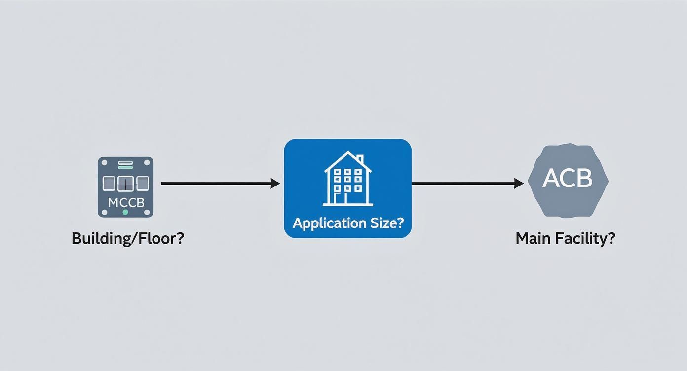
This diagram shows how the scale of your application—from a single floor's distribution panel to an entire facility's main switchgear—helps guide that initial choice between a molded-case (MCCB) or an air circuit breaker (ACB).
As you can see, the MCCB handles branch-level protection, while the heavy-duty ACB stands guard at the main service entrance. This visual makes that first big decision much clearer.
Choosing the Right Brains for the Operation
The final piece of the puzzle is the trip unit—the "brain" of the ABB circuit breaker. This is the component that actually senses an overload or short circuit and gives the command to trip. The two main types offer very different levels of control.
Thermal-Magnetic Trip Units: These are the reliable, workhorse standard. The "thermal" part uses a bimetallic strip that heats up and bends during a long, slow overload. The "magnetic" part reacts instantly to the huge current spike of a short circuit. They’re perfect for straightforward jobs like protecting lighting circuits or simple resistive loads.
Electronic Trip Units: When you get into industrial settings with motors and sensitive machinery, electronic trip units like ABB's Ekip series are in a league of their own. These are microprocessor-based brains that give you incredible control. You can fine-tune the trip settings for long-time (overload), short-time, and instantaneous (short-circuit) events. This precision is key for proper system coordination, ensuring the breaker closest to a fault opens first without taking down an entire production line.
For instance, you can program an electronic trip unit with a slight delay to ride through the normal inrush current of a large motor starting up. A basic thermal-magnetic unit might just see that as a fault and cause a nuisance trip. That's the kind of granular control that keeps a complex facility running smoothly.
Critical ABB Breaker Specifications Explained
This table provides a quick-reference guide to the essential ratings you'll find on any ABB breaker spec sheet and why they are so important.
Specification
What It Means
Why It Matters for Selection
Ampere Frame (AF)
The maximum continuous current the breaker's physical structure can carry.
Defines the breaker's physical size and ultimate current limit. You pick a frame that can house your required trip rating.
Ampere Trip (AT)
The current level where the breaker trips due to an overload.
This has to be matched to the load being protected (e.g., wire ampacity or motor full-load amps) to prevent damage.
Interrupting Capacity (kAIC)
The maximum fault current the breaker can safely interrupt without catastrophic failure.
This is a non-negotiable safety rating. It must be higher than the calculated available fault current where it's installed.
System Voltage
The nominal voltage of the electrical system (e.g., 480V, 600V).
The breaker's voltage rating must always be equal to or greater than the system voltage it's protecting.
By carefully evaluating these four key elements—frame size, trip rating, interrupting capacity, and trip unit technology—you can confidently choose an ABB circuit breaker that delivers the exact safety and performance your system demands.
Weaving Breakers Into Your Industrial Systems
An ABB circuit breaker doesn't work in isolation. You really unlock its value when it becomes a seamless, intelligent part of your larger electrical ecosystem. Think of it less like a standalone gadget and more like a key player on a team, constantly communicating and coordinating to keep your entire system robust, reliable, and safe.
This integration is absolutely crucial in two specific areas of any industrial facility: UL-listed panelboards and Motor Control Centers (MCCs). In these applications, the breaker isn't just a simple safety switch; it's a foundational building block that your operational continuity depends on.
Breakers in the Heart of the Operation: Motor Control Centers
Motor Control Centers are the central nervous system for a plant's machinery. They house the starters, drives, and protective gear for countless motors. The circuit breaker's job here is incredibly specific: protect very expensive motors from electrical faults without causing unnecessary downtime.
This is exactly where an advanced ABB circuit breaker with an electronic trip unit proves its worth. It gives you the granular control needed to tell the difference between a dangerous short circuit and the harmless (but high) inrush current you get when a big motor kicks on. This smart distinction prevents the kind of nuisance tripping that can grind production to a halt.
Here’s the bottom line: coordinated protection is everything. In a properly designed system, a fault on one motor circuit should only trip its dedicated breaker. This isolates the problem instantly, letting the rest of the facility run without missing a beat.
Getting Your System to Talk: Coordination and Communication
Modern industrial plants need more than just basic overcurrent protection; they demand data and communication. The latest ABB breakers come equipped with communication protocols like Modbus and Profibus, allowing them to "talk" directly to your central control system, whether it’s a PLC or SCADA.
This digital link completely changes the game, turning the breaker from a passive device into an active source of intel. It can report on:
Energy Consumption: Pinpoint exactly how much power individual machines are using to spot inefficiencies.
Operational Status: Get real-time feedback on whether the breaker is open, closed, or has tripped.
Fault Diagnostics: When a trip does happen, the breaker can tell you why—overload, short circuit, or ground fault. This slashes troubleshooting time for your maintenance crews.
This level of integration opens the door to predictive maintenance and much smarter energy management. By keeping an eye on a breaker’s performance data, your engineers can spot trends that might signal a developing problem with a motor long before it fails catastrophically.
This push for smart, interconnected electrical gear is a global trend. The Asia Pacific region, for instance, represents the largest piece of the pie, commanding about 45.7% of the total circuit breaker market revenue in 2024, largely driven by massive power grid projects in China and India. You can dig into more insights on the global circuit breaker market on mordorintelligence.com.
The Non-Negotiable: UL-Listed Assemblies
Finally, proper integration isn't just about clever features; it's about certified safety. When you install an ABB circuit breaker in a panelboard or switchboard, the entire finished assembly has to meet incredibly strict safety standards. A UL-listed assembly is your guarantee that the breaker, the enclosure, and all the internal wiring have been tested to work together safely as a single unit.
Mixing and matching components without that certification is a huge gamble. It can easily lead to overheating, bad connections, and a total failure to contain an electrical fault, creating serious fire and arc flash hazards.
For any system integrator or facility manager, specifying a fully tested and UL-listed assembly is simply non-negotiable. It ensures:
Code Compliance: Your system will meet national and local electrical codes, sailing through inspections without the headache of costly rework.
Verified Performance: The breaker's interrupting capacity and thermal limits are guaranteed to perform as expected within that specific enclosure.
Enhanced Safety: The assembly is proven to handle fault conditions safely, protecting both your people and your property.
By focusing on smart coordination, open communication, and certified assemblies, you can leverage the full power of an ABB circuit breaker and make it the cornerstone of a safe, efficient, and incredibly reliable industrial system.
Getting Installation and Maintenance Right
Here’s the thing about even the most advanced ABB circuit breaker: it's only as good as its installation and the care it receives afterward. Think of it like a high-performance race car engine. All that power is worthless without a flawless setup and regular tune-ups. Following best practices isn't just a recommendation; it's the only way to guarantee the long-term safety and performance of your entire electrical system.
This is about more than just ticking a box on a work order. It’s about actively fighting the two biggest enemies of any electrical gear: heat and neglect. A single loose connection or a bit of conductive dust is all it takes to spark a catastrophic failure, turning a critical asset into a dangerous liability.
Let's walk through a practical field guide for getting it right from day one.
Nailing the Installation the First Time
A breaker’s entire life story is written in the first few moments of its installation. When you rush this part, you introduce tiny, hidden weaknesses that might not show up for months or even years. When they do, it’s always a serious problem.
Pay close attention to three things: proper mounting, secure connections, and adequate clearance. Each one is non-negotiable for the breaker to do its job safely, both under normal load and during a fault.
Key Installation Steps:
Check Your Clearances: Make sure there's enough room around the breaker for air to circulate freely. Overheating is the number one killer of circuit breakers, and boxing it in without ventilation basically turns the enclosure into an oven.
Inspect for Damage: Before you even think about installing it, give the breaker a thorough once-over. Look for any cracks or defects in the case and terminals that might have happened during shipping. A compromised case means its structural and insulating properties are shot.
Torque to Spec. No Exceptions: This is the big one. Use a calibrated torque wrench and tighten every line and load connection to the exact manufacturer's spec. Too loose, and you create resistance and heat. Too tight, and you can crack the terminal and damage the breaker.
And of course, always follow the established safety standards. To make sure your work is fully compliant, you should always consult the relevant building codes and regulations.
Proactive Maintenance for Unshakeable Reliability
Once it's installed, an ABB circuit breaker isn't a "set it and forget it" device. A proactive maintenance schedule is your insurance policy against sudden failures and crippling downtime. While a well-cared-for breaker can last 30 to 40 years, that lifespan gets cut short fast in a harsh environment or without regular attention.
Maintenance is all about shifting your mindset from reactive (fixing things when they break) to predictive (spotting trouble before it starts). This means a smart mix of visual checks, mechanical tests, and more advanced diagnostics.
A well-maintained circuit breaker is a predictable asset. A neglected one is an unpredictable risk. Regular maintenance isn't a cost—it's an investment in operational stability and personnel safety.
Your maintenance plan needs to be built around your facility's unique conditions. Is it dusty? Damp? Full of vibration? For a deeper look at what that entails, especially for complex machinery, our guide to motor control center maintenance is a great resource.
Your Essential Maintenance Checklist
Here’s a practical, tiered approach for building out your maintenance schedule, starting with simple routine checks and moving to more involved annual tasks.
Annual Maintenance Tasks:
Infrared (IR) Scanning: Get an IR camera on the breaker while it’s under load. This is the fastest way to spot hot spots at terminals and connections before they can turn into a major failure.
Mechanical Testing: Manually switch the breaker on and off a few times. "Exercising" the mechanism like this ensures the internal lubricants don't gum up and seize.
A Thorough Cleaning: De-energize the system completely and use a vacuum (not compressed air, which just blows dust around) to clean out the breaker and its enclosure. This prevents electrical tracking and flashovers.
Connection Re-Torquing: Heat and vibration can cause connections to loosen slightly over time. After the initial settling-in period, it's smart to verify that all terminals are still torqued to the original spec.
Let's be honest—your facility's electrical system won't last forever. Components get old, technology marches on, and safety standards become more stringent. But what happens when your switchgear is showing its age, but a full, multi-million-dollar replacement just isn't in the budget? It’s a tough spot many facility managers find themselves in.
The good news? You don't always have to rip everything out and start from scratch. A smarter, more targeted approach is to upgrade the single most important component: the circuit breaker. This strategy, known as retrofitting, lets you infuse modern protection and intelligence into your existing gear.
By swapping out those old, tired breakers for a modern ABB model like the Tmax XT or Emax 2, you can give your entire system a new lease on life. You get the benefits of today's tech without the massive cost and downtime of a complete overhaul, stretching the reliable life of your switchgear for years.
Choosing Your Retrofit Strategy
When it's time to upgrade an older breaker, you've really got two main paths: a direct replacement or a full-on retrofit solution. Which one is right for you boils down to the age and model of your existing equipment.
Direct Replacement: This is the easiest route. For breakers from lines ABB recently acquired (like GE Industrial Solutions), you can often find a direct, form-fit replacement. A classic example is swapping an old GE Spectra breaker for a new Tmax XT with very little modification needed.
Retrofit Kits: For ancient or obsolete breakers from other manufacturers, a simple swap is off the table. This is where engineered retrofit kits are a lifesaver. These kits come with custom-designed hardware—think busbar adapters and mounting plates—that allow a modern ABB circuit breaker to be installed safely and securely inside an older switchgear cabinet.
Retrofitting isn't just a patch-up job; it's a strategic modernization. It lets you tackle the highest-risk parts of your system first, boosting safety and reliability in a big way while pushing massive capital spending further down the road.
Weighing the Costs and Benefits
The decision to retrofit or replace always comes down to a hard look at the costs and benefits. A full switchgear replacement is a massive capital project that almost always involves extended downtime—the kind that can bring production to a grinding halt.
A targeted breaker retrofit, on the other hand, is more like a surgical procedure. It can often be done in a fraction of the time, usually during a planned maintenance window, keeping operational disruptions to a minimum. While a high-tech breaker and a custom retrofit kit aren't cheap, the cost is almost always just a fraction of a full system replacement.
And just look at the tangible benefits you get:
Enhanced Safety: Modern breakers are simply better at what they do, offering far superior arc flash mitigation and more dependable fault interruption.
Improved Reliability: New components mean you're no longer gambling on old, worn-out mechanical parts. A well-cared-for breaker can last 30 to 40 years, and a retrofit essentially resets that clock.
Advanced Monitoring: When you upgrade to a breaker with an electronic trip unit, like an Emax 2, you suddenly unlock communication capabilities. That old switchgear can now feed you critical data on energy consumption and system health.
Simplified Maintenance: New breakers, especially the plug-in models, can slash maintenance time and effort by getting rid of the need to constantly re-torque connections.
Ultimately, retrofitting an ABB circuit breaker into your existing system is a powerful move. It delivers the most important safety and performance upgrades right where they count, buying you invaluable time and extending the life of your most critical electrical assets.
Got Questions About ABB Breakers? We've Got Answers.
Even after you've done your homework, a few specific questions always seem to pop up when it's time to choose, install, or upgrade an ABB circuit breaker. We get it. That's why we’ve put together some quick, straightforward answers to the questions we hear most often from engineers and facility managers out in the field.
Think of this as your go-to guide for getting clear on the details so you can make decisions with confidence.
What's the Real Difference Between an ABB MCCB and an ACB?
The biggest distinction boils down to three things: where it's used, how it's built, and how much power it can handle.
A Molded Case Circuit Breaker (MCCB), like ABB's workhorse Tmax XT series, is what you'll find protecting individual circuits, feeders, and motors all over a facility. They typically handle currents up to 3200A. Just like the name says, all its guts are sealed inside a compact, non-serviceable molded case.
On the other hand, an Air Circuit Breaker (ACB), like the beastly Emax 2, is the guardian at the gate. You'll find it at the main service entrance of a large facility, where it protects the entire building from a catastrophic fault. These are rated for massive currents, up to 6300A or even more. An ACB uses the surrounding air to extinguish the huge electrical arc when it trips and is designed with components that can be serviced, giving it a much longer operational life.
How Do I Pick the Right Trip Unit?
Choosing the right trip unit—the "brain" of the breaker—is absolutely crucial. It's what matches the protection to the exact piece of equipment it's supposed to be guarding.
Thermal-Magnetic Trip Units: These are the dependable, cost-effective standard for basic overload and short-circuit protection. They are the perfect fit for simpler, less critical loads like lighting panels or resistive heaters.
Electronic Trip Units: When you need precision and flexibility, you step up to an electronic unit like ABB’s Ekip series. These let you fine-tune everything—long-time, short-time, and instantaneous trip settings. This level of control is essential for protecting expensive motors and getting selective coordination right in a complex system.
Here's a simple rule of thumb: If you just need basic protection, thermal-magnetic will do the job. But if you're protecting motors, coordinating a multi-layered system, or you need advanced diagnostics and communication, an electronic trip unit is a must.
Can I Swap Out Another Brand's Breaker for an ABB Model?
This is a question we hear all the time, especially when dealing with older facilities. A direct, one-for-one physical swap is almost never possible because of differences in size and how they mount. But the answer is still usually yes—with a retrofit.
ABB has engineered retrofit solutions that come with custom adapter plates and busbar connections. These kits allow a modern, feature-rich ABB circuit breaker to be installed safely into an older switchgear cabinet that was built for a competitor's breaker that is now obsolete. It’s a smart way to bring your system's protection and reliability into the 21st century without the staggering cost and downtime of replacing the entire switchgear.
At E & I Sales, this is what we do day in and day out. Whether you’re just selecting a new breaker, planning a full-scale retrofit, or designing a complete UL-listed control panel from scratch, our team has the hands-on expertise to make sure you get a reliable, code-compliant solution that just works. Reach out and let's talk about your project at https://eandisales.com.
A microgrid control system is the command center—the digital brain—of a localized power grid. It’s what manages all the moving parts, from energy generation and storage to final distribution.
Think of it like the conductor of an orchestra, making sure every instrument—whether it’s solar panels, backup generators, or battery banks—plays its part in perfect harmony to deliver clean, reliable power.
The Brains Behind Resilient Power
Picture a hospital, a bustling manufacturing plant, or a mission-critical data center. For them, a sudden outage from the main utility isn't just an inconvenience; it can be catastrophic. This is exactly where a microgrid, guided by its intelligent control system, proves its worth. It can operate as a self-sufficient energy island, completely disconnected from the main grid when needed.
The microgrid control system is the decision-making engine that makes this all possible. It’s constantly watching grid conditions, tracking energy prices, and anticipating the facility’s power needs. If it senses a problem, like a voltage dip that signals an impending blackout, it can seamlessly switch the entire facility over to its own power sources.
This transition happens in milliseconds—so fast that sensitive equipment keeps running without a single hiccup.
Why This Control Is So Important
At its core, a control system’s job is to maintain that delicate balance between electricity supply and demand. This gets a lot more complex inside a microgrid, which often has to juggle multiple, variable energy sources.
Here's what it handles:
Ensuring Grid Stability: It actively manages voltage and frequency to maintain high-quality power, whether you're connected to the utility or running on your own.
Optimizing Energy Costs: The system is smart enough to decide when to use stored battery power, pull from the grid when rates are low, or even sell excess solar energy back to the utility. It's all about minimizing what you spend.
Integrating Renewables: It smooths out the peaks and valleys of solar and wind power by coordinating them with battery storage and other generators, guaranteeing a consistent and predictable energy supply.
A microgrid's true value isn't just in its physical assets like batteries and generators. It's in the intelligence of the control system that orchestrates them. This digital layer is what unlocks real resilience, efficiency, and sustainability.
A Rapidly Growing Market
It's no surprise that demand for these advanced systems is surging. As more industries look for greater energy independence and reliability, the market is taking off.
The global microgrid control systems market shot up from an estimated $4.05 billion to a projected $4.74 billion in just one year. This explosive growth is being driven by the need for a more modern grid and better ways to manage renewable energy. You can dig deeper into these market dynamics over at Mordor Intelligence. This trend really highlights the critical role these systems play in building a more resilient energy future.
Core Architectures of Microgrid Control
Just like there are different ways to run a company, microgrid control systems have a few distinct blueprints. The architecture you choose dictates how decisions get made, how information flows, and ultimately, how fast the system can react when things change. Getting this right is fundamental, whether you're managing a single factory or a sprawling campus.
We generally see three main approaches: centralized, hierarchical, and distributed. Each has its own operational logic, and understanding the trade-offs is the first step toward building a system that’s both smart and tough.
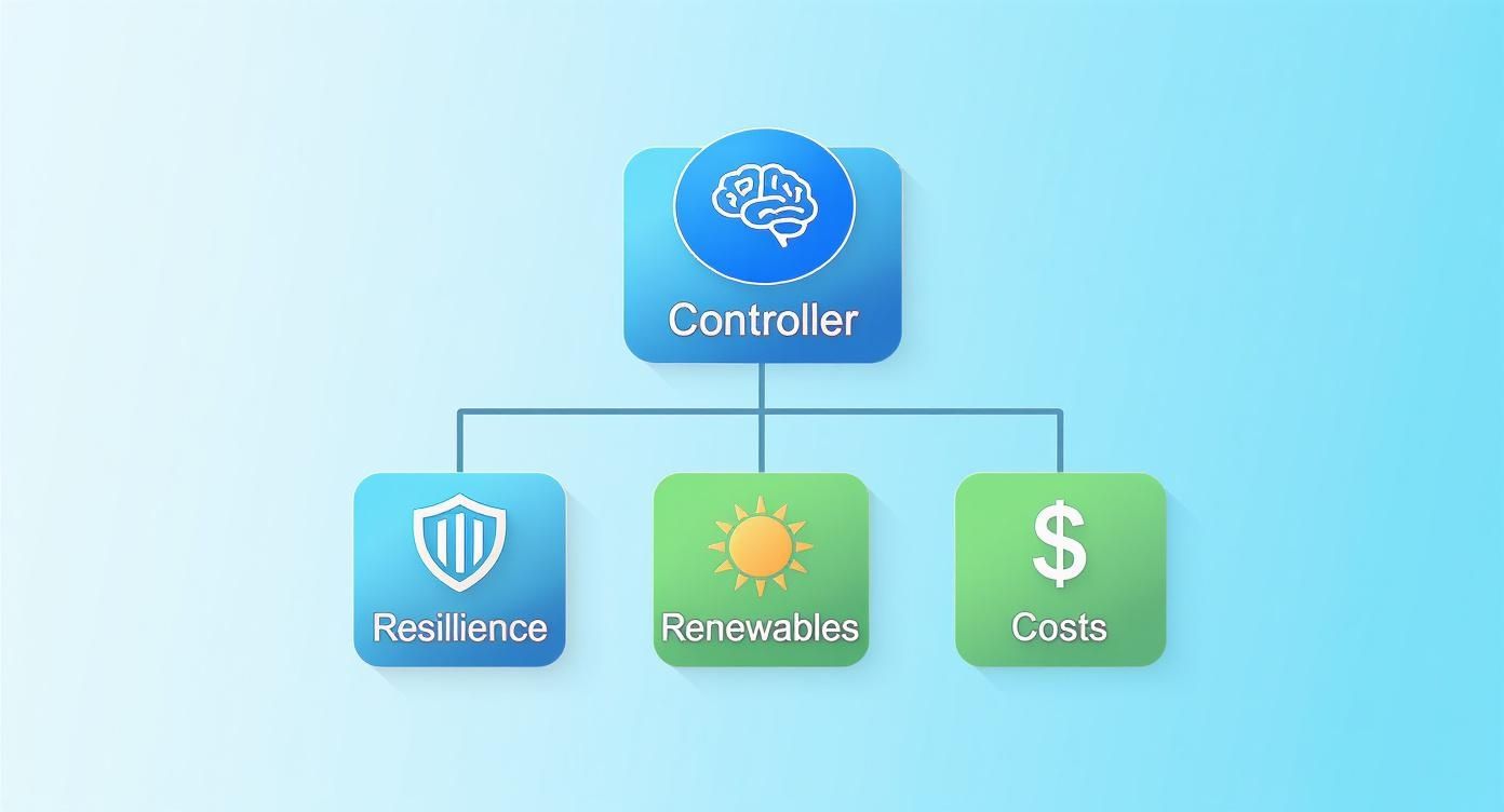
The controller's job is a constant balancing act. It has to juggle the competing demands of resilience, renewable energy integration, and cost management. Every decision tips the scales one way or another.
This constant push and pull between reliability, sustainability, and economics is at the heart of what a good control system does.
Centralized Control: The Single Commander
The centralized model is the classic, top-down approach. Think of it like a military command center with one all-powerful brain—the Microgrid Central Controller (MGCC). This single unit pulls in data from every generator, battery, and load, crunches the numbers, and sends out direct orders.
This design makes management straightforward since all the intelligence lives in one place. It’s fantastic for system-wide optimization because the MGCC has a bird's-eye view, allowing it to make the most efficient and cost-effective calls.
But there's a catch: this design has a glaring vulnerability. If that central controller goes down, the whole microgrid can go dark with it. This single point of failure makes it a risky choice for applications where uptime is everything.
Hierarchical Control: A Team of Managers
A hierarchical setup offers a more layered and robust structure. You still have a central controller at the top, but it delegates authority to local controllers that manage specific zones or groups of equipment. For example, one local controller might handle a solar array and its battery, while another is in charge of a block of industrial machinery.
It’s a lot like how a big factory is run—a main supervisor oversees several floor managers. The top controller sets the big-picture strategy (like "let's save money today"), and the local units handle the second-by-second execution. This takes a huge load off the main controller and speeds up response times.
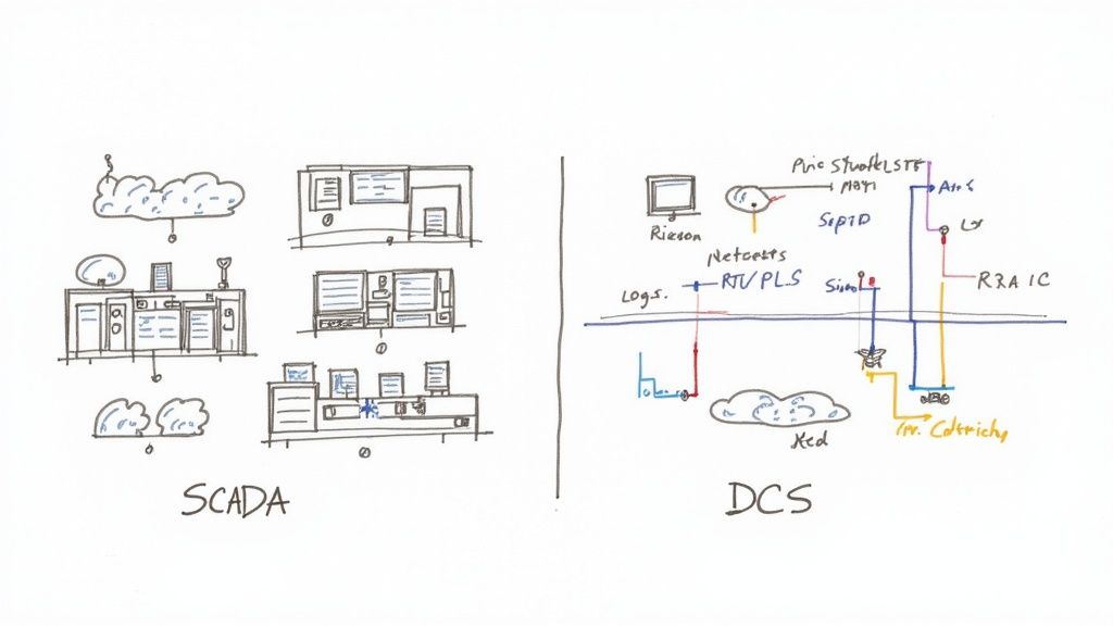
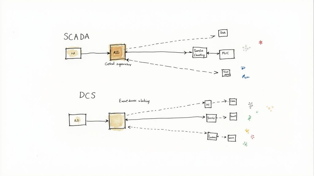
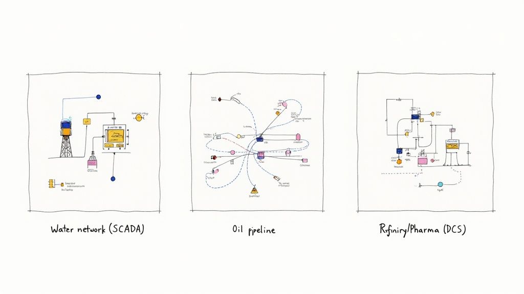
Many large-scale systems are built this way, often blending technologies like SCADA and DCS. If you want to dive deeper into those, we have a guide that breaks down the SCADA and DCS control systems.
The real beauty of this layered approach is the built-in redundancy. If a local controller fails, it only affects its own little zone. The rest of the microgrid keeps on running, guided by the central brain.
Distributed Control: The Collaborative Network
The distributed, or decentralized, architecture is the most modern and resilient of the bunch. Here, there’s no single boss. Instead, intelligent controllers embedded in each device talk directly to one another on a peer-to-peer network.
Imagine a highly skilled team where every member makes autonomous decisions based on what their colleagues are doing. A solar inverter, a battery system, and a generator all adjust their own output to keep the grid stable, all without waiting for orders.
Enhanced Resilience: With no single point of failure, the system is incredibly tough. If one component drops out, the others automatically pick up the slack.
Scalability: Adding a new solar panel or battery is a breeze. The new device simply joins the network and starts contributing.
Rapid Response: Decisions are made locally and instantly. This is perfect for handling the fast-changing conditions common with renewable energy.
This "plug-and-play" nature makes distributed microgrid control systems exceptionally flexible and robust—a perfect fit for complex sites with a diverse mix of energy assets.
Comparing Microgrid Control Architectures
Each architecture brings something different to the table. Choosing the right one depends entirely on your project's specific needs for resilience, cost, and scalability.
Architecture
Control Logic
Key Advantages
Key Disadvantages
Best For
Centralized
Top-down; one master controller (MGCC) makes all decisions.
Simple to manage; optimal for system-wide economic dispatch.
Single point of failure; communication bottlenecks can slow response.
Small, simple microgrids where cost optimization is the primary goal.
Hierarchical
A central controller coordinates multiple local controllers.
Balanced approach; improved reliability and faster local responses.
More complex to design and implement than a centralized system.
Large industrial campuses or utility microgrids with distinct zones.
Distributed
Peer-to-peer; intelligent devices communicate and decide locally.
Highest resilience (no single point of failure); easily scalable.
Complex control algorithms; system-wide optimization is more challenging.
Mission-critical facilities and microgrids with many diverse energy sources.
Ultimately, the goal is to match the control philosophy to the operational reality. A simple system might thrive with a centralized brain, while a complex, dynamic one will benefit from the collaborative intelligence of a distributed network.
Essential Microgrid Operating Modes
A microgrid’s real value comes from its ability to adapt. The control system is the brain behind this flexibility, constantly ready to shift its behavior to keep the lights on, no matter what’s happening on the main utility grid. Think of it as a seasoned musician who can play in a full orchestra, lead a small ensemble, or perform a stunning solo at a moment's notice.
This operational agility is the bedrock of microgrid resilience. The controller has to fluidly transition between these modes to guarantee stability, whether it’s running in sync with the utility or standing entirely on its own.
Grid-Following: The Synchronized Player
Most of the time, a microgrid operates in grid-following mode. While connected to the utility, it behaves like a disciplined musician in a large orchestra. The main grid is the conductor, setting the tempo—the voltage and frequency—and the microgrid’s inverters simply follow that lead.
The focus here is purely economic. The control system is busy with tasks like:
Managing Power Flow: It intelligently decides when to push surplus solar power back to the grid for credits or pull power from the utility when rates are low.
Optimizing Local Assets: It juggles its own generators and batteries to slice the facility's energy bills, a practice we call economic dispatch.
This is the standard, efficient mode for daily operations. But it’s completely dependent on a stable utility grid. If the conductor falters, the microgrid must be ready to switch roles instantly or risk going down with it.
Grid-Forming: The Conductor
When the microgrid disconnects from the utility, it immediately enters grid-forming mode. Now, it has to become the conductor. It must create its own stable rhythm from scratch. The control system instantly assigns one or more of its inverters—usually those tied to a battery system—to generate and maintain a clean, stable voltage and frequency for the entire site.
This is a much tougher job. The grid-forming inverters become the undisputed source of power quality. They establish the beat that all other generators, solar arrays, and equipment on the microgrid must sync to. This is the crucial function that transforms a collection of individual assets into a cohesive, self-sufficient power system.
Islanding: The Solo Performance
The act of separating from the grid is known as islanding. This is the critical moment when the microgrid executes a flawless, planned break from the utility during an outage and begins its solo performance. A high-speed breaker at the point of common coupling (PCC) physically opens in milliseconds to create the "island."
The ability to seamlessly island is the hallmark of a resilient microgrid. It’s the planned, controlled separation from a failing utility grid that ensures critical loads—like hospital equipment or manufacturing lines—never experience an interruption.
Once islanded, the microgrid control system takes complete command. It has to perfectly balance its internal power generation with the site's real-time energy demand. The microgrid can continue this solo act for as long as needed—hours, days, or even weeks—until the utility grid is stable again. At that point, it can safely resynchronize and return to its normal grid-following role.
The growing demand for this kind of sophisticated control is obvious in the market. The global microgrid controller software market is projected to skyrocket from $5.06 billion to $33.90 billion in just a decade, a massive annual growth rate of 23.55%. You can explore more insights into this expanding market at Precedence Research. This explosion in growth shows just how vital this advanced software is to achieving true energy independence and resilience.
Talking the Talk: Microgrid Communication Protocols and Standards
A microgrid controller is like the conductor of an orchestra. But what happens if the conductor only speaks English, the strings speak French, and the brass section speaks German? You get noise, not music. The same chaos happens in a microgrid when devices from different manufacturers can't communicate effectively.
This is where communication protocols and industry standards become the unsung heroes of the project. Protocols are the common languages that allow all the equipment—from inverters to generators—to share data and commands. Standards are the rulebooks that ensure everything is connected safely and plays nice with the larger utility grid. Without them, you don't have an intelligent, unified system; you just have a very expensive collection of parts.
The Languages of Industrial Control
Over the years, a few key protocols have become the go-to languages for the energy and industrial worlds. A truly capable microgrid control system needs to be multilingual, speaking the native tongue of every asset you connect to it.
IEC 61850: Think of this as the high-speed, modern language of substations and smart grid devices. It’s built for the rapid-fire, peer-to-peer communication needed for protective actions that keep a microgrid stable during a fault. Its structured, object-oriented approach to data is a huge win for simplifying integration.
DNP3 (Distributed Network Protocol 3): A long-time favorite of North American electric utilities, DNP3 is the rugged, reliable choice. It's fantastic for SCADA systems talking to remote equipment over networks that might not be perfect, ensuring critical messages get through no matter what.
Modbus: This one is the old, reliable workhorse. As one of the most widely adopted industrial protocols ever, Modbus is your key to connecting with all sorts of factory equipment, sensors, and meters. Its simplicity is its strength, making it a must-have for bringing older, legacy assets into your microgrid.
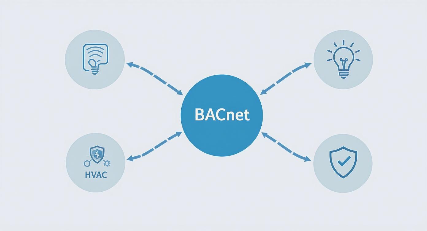
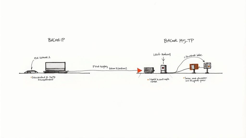
And you can't forget about BACnet, which is incredibly common in building management systems. If your microgrid needs to integrate with a facility's HVAC or lighting controls, you'll need to know your way around it. For a deeper dive, check out our complete guide to the BACnet communication protocol.
The diagram below shows how a standard like IEC 61850 organizes this communication traffic into logical layers, from the equipment on the ground floor all the way up to the central control room.
This layered design is what keeps everything organized and prevents a communication free-for-all, ensuring data flows where it needs to, when it needs to.
The Rulebook for Playing with the Grid
Beyond just speaking the right language, a microgrid has to follow a strict set of rules, especially when it’s connected to the main utility. In the United States, the single most important rulebook is IEEE 1547.
IEEE 1547 is the master standard that lays out all the technical requirements for connecting distributed energy resources (like your microgrid) to the electric grid. This isn't just a suggestion—compliance is your ticket to legally and safely interconnecting with the utility.
Following this standard means your microgrid acts like a good neighbor. It dictates exactly how your system must react to grid problems, how it should support overall grid stability, and—most critically—how it must stop sending power back to the utility's lines during an outage to keep line workers safe. Making sure your inverters and controllers are certified to the latest version of IEEE 1547 isn't just a box to check; it’s a fundamental part of a safe and successful project.
The push for this kind of intelligent, compliant technology is driving some serious market growth. The global microgrid controller market is forecast to explode from USD 3 billion to USD 22.4 billion over the next decade, a blistering annual growth rate of 22.3%. This incredible expansion is a direct result of the growing demand for real-time, smart energy management. You can discover more insights on this market growth at Global Market Insights Inc.
Alright, let's get this section sounding like it was written by a seasoned pro who's been in the trenches, designing these systems for years.
Here is the rewritten section, following the specified style, tone, and requirements.
Designing and Integrating Your Microgrid System
Getting a microgrid from the drawing board to a fully operational reality is where the rubber meets the road. For an industrial site, this is a serious undertaking, and every bit of planning you do upfront will pay you back tenfold down the line. It all starts with getting to know the unique energy heartbeat of your facility.
This isn't just about picking out shiny new hardware. It’s about building a finely tuned ecosystem where every single component pulls in the same direction, delivering the resilience and efficiency you’re after.
Start with a Detailed Load Profile
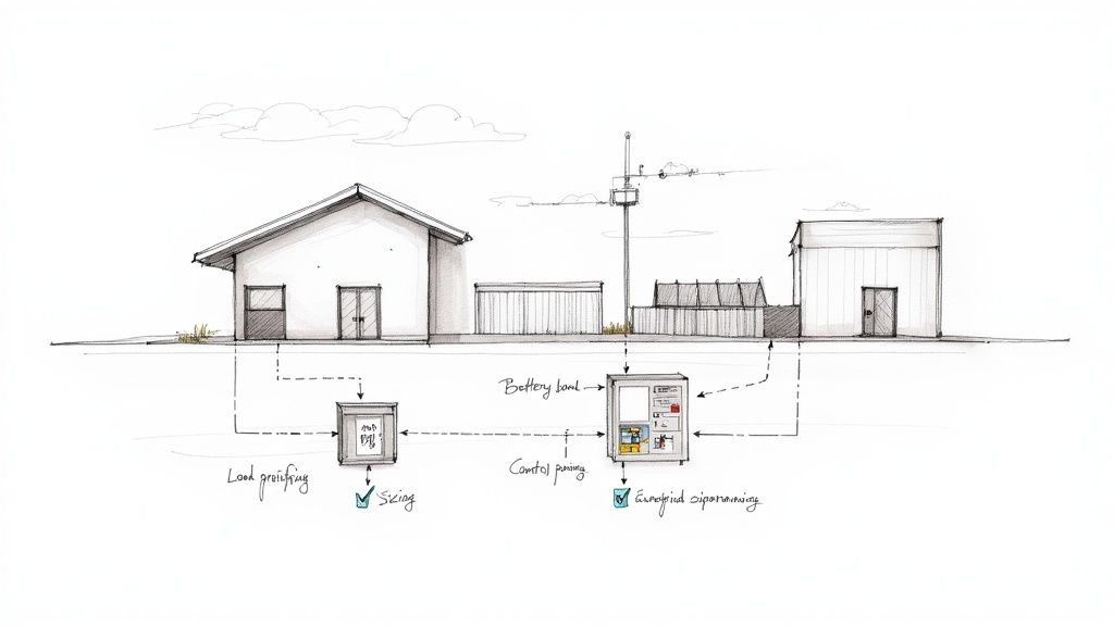
Before you even think about specifying a single piece of equipment, you absolutely have to know how, when, and where your facility uses electricity. This is what we call load profiling, and it's non-negotiable.
Think of it as an energy audit on steroids. You’ll dig into your consumption data over a long period to pinpoint critical loads, identify those costly peak demand windows, and truly understand your operational patterns. This data becomes the bedrock for every other decision you make, from sizing your battery bank to choosing the right control architecture. A solid load profile tells you exactly what must stay running during an outage and what can be shed to conserve precious power.
Sizing Your Energy Resources and Control
With that load profile in your back pocket, you can start sizing your Distributed Energy Resources (DERs). This is a careful balancing act, weighing your operational needs against the hard realities of your budget.
Battery Energy Storage System (BESS): This needs to be big enough to carry your most critical loads for a set amount of time during an outage and to help you shave those expensive demand peaks.
Generation Assets: Whether it's solar panels or generators, they need enough muscle to meet your demand and recharge your batteries—even on cloudy days or during a multi-day grid failure.
Control System Selection: Your choice between a centralized, hierarchical, or distributed control system really depends on your site’s complexity. For mission-critical industrial operations, we often lean toward a distributed model simply because of its built-in redundancy.
A classic mistake is getting the sizing wrong. Go too big, and you've wasted capital. Go too small, and the system will fail you when you need it most. Proper sizing, guided by your load profile, is the key to hitting that sweet spot.
Smart Procurement for Faster Integration
How you buy your components can make or break your project timeline. Instead of sourcing every little part and trying to build it all from scratch on-site—a recipe for delays and headaches—a much smarter approach is to use pre-engineered, packaged solutions.
Specifying a UL-listed control panel is a huge step in the right direction. This certification means the panel has been built and tested to strict, nationally recognized safety standards. It shows up on your site ready to go, which dramatically cuts down on field wiring, testing time, and commissioning nightmares. This approach to industrial controls and automation is how you get a faster, safer, and more reliable deployment.
Commissioning and Verification Checklist
The last mile is commissioning. This is the systematic, step-by-step process of testing every component and function to prove the system does what you designed it to do. This is where you find out if your microgrid can actually handle the scenarios you’ve been planning for.
A rock-solid commissioning plan must include:
Component-Level Testing: Confirming every inverter, generator, and battery is talking correctly to the controller.
Full System Functional Tests: Running simulations of different operating conditions, including a planned islanding event.
Black Start Capability Test: Proving the system can bring itself back online from a total shutdown with zero help from the utility grid.
Compliance Verification: Making sure the system checks all the boxes for your utility's interconnection requirements. It’s also vital to ensure you're aligned with any applicable national standards and UK grid regulations like G98, G99, and G100.
Only when your system passes these grueling tests with flying colors can you finally be confident that your microgrid is ready to deliver the resilience and control you paid for.
Securing Your Microgrid from Cyber Threats
As microgrids get smarter and more connected, they also show up more brightly on the radar of cyber attackers. The very things that make them so powerful—remote access, live data streams, and automated controls—unfortunately double as open doors for disruption.
Common-sense oversights like internet-exposed controllers, lax remote access for vendors, and unmonitored industrial protocols are the low-hanging fruit for bad actors. Let’s be clear: cybersecurity for your microgrid control system isn’t an add-on anymore. It’s a fundamental operational requirement.
A Layered Defense-in-Depth Strategy
The old "castle-and-moat" security model is dead. Building a strong perimeter and trusting everything inside is a recipe for disaster. Once an attacker is inside that wall, they have free rein. The modern playbook calls for a "defense-in-depth" strategy, which assumes a threat can originate from anywhere, inside or out.
This approach involves several critical layers:
Network Segmentation: This is about creating bulkheads in your ship. You divide the control network into smaller, isolated zones. If one area is breached, the damage is contained and can’t sink the entire system.
Strict Access Control: Every remote access point needs multi-factor authentication, period. It's also crucial to operate on the principle of least privilege—users and devices should only have the absolute minimum access required to do their job. Nothing more.
Data Encryption: Think of this as sealing your communications in an envelope. All data flying between controllers, inverters, and other devices must be encrypted. This stops attackers from listening in on commands or, worse, injecting their own malicious data.
Modern security philosophies like a robust Zero Trust Architecture are quickly becoming the standard for stopping sophisticated attacks. The premise is simple but powerful: never trust, always verify. Every single connection, every single data packet gets verified.
Adhering to Cybersecurity Frameworks
There's no need to start from scratch. Proven, battle-tested frameworks give you a roadmap for building a resilient operation. The NIST Cybersecurity Framework is one of the most respected guides out there for protecting critical infrastructure.
The Framework provides a structured, risk-based approach to cybersecurity, organizing activities around five core functions: Identify, Protect, Detect, Respond, and Recover. It helps you understand, manage, and reduce cybersecurity risk in a way that’s aligned with your business objectives.
What makes the framework so effective is that it creates a common language and a repeatable methodology that everyone—from the engineer on the plant floor to the executive in the boardroom—can understand and follow.
NIST visualizes these five functions as a continuous cycle, not a one-and-done checklist.
This integrated approach drives home the point that security isn't a project with an end date. It's a constant process of improvement and adaptation to whatever new threats come next.
By building a layered defense, locking down access, and following established standards like the NIST Framework, you can develop a security posture that’s truly robust. This proactive stance is the only way to safeguard your microgrid control system, ensuring it remains an asset for resilience, not a point of failure.
Frequently Asked Questions
When you start digging into microgrid controllers, a few common questions always seem to pop up. Let's tackle some of the most frequent ones to clear up the details, especially when you're comparing technologies or planning future upgrades.
Controller Versus Building Automation
What’s the real difference between a microgrid controller and a building automation system (BAS)?
Think of them as two different managers running the same facility, each with a very specific job. The microgrid control system is your power czar. It’s completely focused on energy generation, storage, and grid stability. Its prime directive is to keep the lights on with reliable power, no matter what—especially if it has to island from the utility.
A Building Automation System (BAS), on the other hand, is the efficiency guru. It looks inward, managing all the building loads like HVAC and lighting to keep everyone comfortable while cutting energy waste. While these two systems absolutely can and should talk to each other, the microgrid controller always has the final say on power, while the BAS handles the building's internal climate and environment.
Integrating with Existing Solar
Can I add a microgrid control system to the solar panels I already have?
Absolutely. In fact, this is one of the most common and powerful ways to upgrade a facility. A modern microgrid controller can be retrofitted to work with existing assets like solar arrays and backup generators, essentially giving them a new, much smarter brain.
The controller steps in as the new command center, coordinating your legacy equipment with new components like a battery energy storage system (BESS). This creates a cohesive, fully functional microgrid. The most important step is just making sure the controller you pick can "speak the same language" by supporting your existing equipment's communication protocols.
This ability to integrate what you already own is a huge deal for making microgrids more accessible. It means facilities can upgrade their energy systems in phases, adding advanced control and storage to unlock the full potential of equipment they’ve already paid for.
The Role of AI and Machine Learning
How are AI and machine learning changing microgrid control systems?
Artificial intelligence and machine learning are giving microgrid controls a crystal ball. Instead of just reacting to what’s happening right now, these advanced systems can predict what's coming next—and that’s a total game-changer for efficiency and cost savings.
Here’s how they make a real difference:
Predictive Forecasting: AI algorithms can chew through weather data to predict, with surprising accuracy, how much solar energy your panels will produce tomorrow.
Load Prediction: By analyzing historical consumption data, machine learning models can forecast your facility’s energy demand with incredible precision.
Having this kind of foresight lets the microgrid control system make much smarter, proactive decisions. It can store excess solar power when it knows a cloudy day is on the horizon or pre-charge batteries right before a predicted spike in demand. This isn't just clever tech; it directly optimizes your operating costs and makes the entire system run better.
At E & I Sales, we specialize in designing and delivering the robust, UL-listed control panels that are the heart of any reliable microgrid. From initial spec to final commissioning, our team delivers the integrated solutions that bring your energy resilience goals to life. See how our expertise can power your next project at https://eandisales.com.
A control panel builder is a specialized company that designs, builds, and tests the electrical control systems for industrial machinery. Think of them as the architects of your equipment’s nervous system. They take your operational goals and translate them into a physical control system that’s safe, efficient, and ready to work.
What Does a Control Panel Builder Really Do?
Sure, they build panels. But their real job is to be a critical engineering partner. They take a list of your needs—controlling motor speeds, reading sensors, activating safety locks—and turn it into a functional piece of hardware. This isn't just about connecting wires; it's a careful mix of electrical engineering, deep knowledge of regulations, and hands-on craftsmanship.
These builders create a unified system that becomes the command center for your entire operation. Their work is what ensures every button press and automated sequence happens exactly when and how it should, protecting both your expensive machinery and your people.
The Core Mission of a Builder
When you get right down to it, a builder's main job is to provide certainty. Partnering with a professional builder means handing off a highly specialized and critical task to experts who live and breathe electrical code and automation logic. They handle the complexity so you can focus on running your business.
This breaks down into a few key areas that show their true value:
Turning Ideas into Hardware: They take your P&IDs (piping and instrumentation diagrams) or even just a functional description and engineer a tangible solution that works in the real world.
Keeping Things Safe and Legal: A good builder knows the standards inside and out. They design and build panels to meet strict requirements from organizations like UL (Underwriters Laboratories), ensuring the final product is safe, reliable, and insurable.
Choosing the Right Parts for the Job: They select the best components—from PLCs and VFDs to breakers and terminals—to make sure the panel can handle the specific demands of your operation without fail.
Supporting You from Start to Finish: The job doesn't end when the panel is built. The best builders provide complete documentation, rigorous testing, and even on-site commissioning to make sure everything integrates smoothly.
A skilled control panel builder is the bridge between your operational vision and the physical hardware that makes it happen. They turn abstract requirements into a robust, safe, and fully functional electrical system.
This isn't a niche market, either. The global industrial control panels market was valued at USD 13.5 billion in 2023 and is on track to hit around USD 20.8 billion by 2032. That growth shows just how much modern industries rely on automation to stay competitive and safe. You can explore more about these market trends and their drivers.
In the end, a control panel builder delivers more than just a box with wires. They provide a critical asset engineered for dependability, forming the very backbone of modern industrial automation.
From Blueprint to Operation: Core Builder Services
A professional control panel builder does a lot more than just screw components onto a backplate. They take a project on a structured, multi-stage journey, turning a simple operational need into a control system that’s functional, safe, and built to last.
Think of it like getting a custom suit made. You don't just hand over fabric; you work with a master tailor who measures, designs, cuts, and stitches everything with precision. They ensure the final product fits perfectly and looks sharp. That’s what a great panel builder does for your industrial controls.
Each phase demands a specific mix of engineering know-how, deep regulatory knowledge, and old-fashioned hands-on craftsmanship. Let's walk through the four core services that separate the pros from the amateurs.
Collaborative Design and Engineering
It all starts with an idea. The journey begins by turning your concept into a concrete, manufacturable plan. Honestly, this is the most critical phase—every decision made here ripples through the panel's final performance, safety, and cost.
A skilled builder works with you to nail down the exact operational requirements. This isn't just about taking orders; it’s a deep-dive conversation where they ask the tough questions to head off problems before they start:
Where will this panel live? Is it indoors, outdoors, or in a hazardous location?
What are the real power requirements and motor loads we're dealing with?
What communication protocols need to play nicely together, like Ethernet/IP or Modbus?
What specific safety interlocks are non-negotiable for protecting people and machinery?
Armed with this information, their engineers draft detailed electrical schematics, enclosure layouts, and a full bill of materials (BOM). This blueprint becomes the single source of truth for the entire project, ensuring every part is specified and placed for peak function and easy servicing down the road.
Precision Fabrication and Assembly
Once the design is locked in, the project moves from the screen to the shop floor. This is where expert craftsmanship truly shines. The fabrication happens in a controlled environment, carried out by certified technicians who live and breathe industrial control panels.
The whole process is methodical and precise. Technicians mount the backplate, lay down DIN rails, and carefully place every single component—from the main breaker and PLC right down to the terminal blocks and wire ducts. The wiring itself is practically an art form. Each connection is cut to the perfect length, clearly labeled, and torqued to spec. A clean, well-organized panel isn't just nice to look at; it's a thousand times easier to troubleshoot and safer to maintain.
A messy, disorganized panel is a huge red flag. The level of care a builder puts into wire management and labeling speaks volumes about their commitment to quality and long-term reliability.
This stage is all about bringing the schematics to life with an uncompromising focus on the small stuff.
UL Listing and Regulatory Compliance
One of the single most important services a qualified panel builder offers is ensuring the final product meets all industry standards—especially UL 508A. This certification is the gold standard for industrial control panel safety in North America.
A UL 508A Listed panel means it was built in a certified shop, using approved components, and following a strict set of construction rules. This isn't just about getting a sticker for the enclosure. It provides a few critical guarantees:
Safety Verification: It confirms the panel was designed and built to protect against fire and electrical shock.
Code Acceptance: Inspectors and regulators across the country recognize the UL mark, which can save you massive headaches and delays during project approvals.
Insurability: Good luck getting a policy without it. Many insurance providers require critical electrical equipment to be UL Listed.
When a builder maintains an active UL 508A certification, it shows a serious commitment to safety and quality. It gives you peace of mind that your panel isn't just going to work, but it's going to be fundamentally safe.
Commissioning and Field Support
A great builder knows their job isn't done when the panel ships out the door. The final, crucial step is making sure it integrates smoothly into your facility and performs exactly as designed. That’s where commissioning and field support come in.
Commissioning means on-site technicians power up the panel, verify every I/O point, check motor rotations, and confirm all automated sequences run flawlessly. They troubleshoot any hiccups that pop up during startup, working right alongside your team to fine-tune the system. This final check makes the transition from installation to full-throttle operation as smooth as possible.
Beyond that, a reputable builder provides comprehensive documentation—we’re talking as-built drawings and operation manuals—that becomes invaluable for future maintenance. Exploring the full scope of custom controls and their lifecycle support will give you a much deeper insight into what to expect from a true partner.
Decoding Technical Specifications and Standards
To get the most out of a partnership with a control panel builder, you need to speak their language. Don't worry, this isn't about becoming an electrical engineer overnight. It's about understanding the core technical specs and standards that shape your project's safety, reliability, and final cost.
Getting these details right from the very beginning is the single best way to prevent expensive rework down the road. Think of your specifications as the DNA of your control panel—they define everything from the toughness of its steel box to the "brain" running the whole show. A vague request gets you a generic panel, but a precise spec sheet lets a builder craft a system that fits your operation like a glove.
This precision is more important than ever. The global electric control panel market was valued at around USD 7.48 billion in 2025 and is on track to hit USD 11.1 billion by 2032. That growth is all about automation and tighter safety rules, making clear, accurate specs non-negotiable. You can learn more about the electric control panel market growth and its drivers.
NEMA And UL Ratings Explained
When you're talking about enclosures, you'll hear NEMA and UL ratings thrown around a lot. They aren't the same thing, but they both tell you how well an enclosure can protect the sensitive electronics inside from the outside world.
Think of a NEMA rating as the enclosure’s "armor class." It tells you exactly what kind of abuse it can handle. A NEMA 1 enclosure is perfectly fine in a clean, dry office, but it would fail in a heartbeat in a washdown area. On the other hand, a NEMA 4X enclosure is built to shrug off corrosion and high-pressure water jets, making it the go-to for food processing plants or marine environments.
UL ratings, specifically UL 508A, take it a step further. While NEMA sets the performance standard, a UL Listing is proof that a control panel builder has actually built and tested a panel to meet that standard, certifying it's safe from fire and electrical hazards.
To help you get started, here's a quick rundown of some common NEMA ratings you'll encounter.
NEMA Enclosure Ratings Explained
NEMA Rating
Protection Against
Common Application Environment
NEMA 1
Falling dirt, dust, and accidental contact
Indoor, non-hazardous locations like offices or labs.
NEMA 3R
Rain, sleet, snow, and external ice formation
Outdoor locations that are generally protected.
NEMA 4X
Corrosion, windblown dust, rain, and hose-directed water
Food processing, marine, or chemical plants.
NEMA 12
Dripping non-corrosive liquids, falling dirt, and dust
Indoor industrial settings like factories or warehouses.
Knowing just these four ratings will give you a solid foundation for specifying the right enclosure for almost any job.
This entire process, from the first sketch to long-term support, is critical for delivering a system that’s not just functional, but also safe and compliant.
Core Components And Their Functions
Inside the box, a few key components do all the heavy lifting. Knowing what they are and what they do will help you have much smarter conversations with your builder.
A Motor Control Center (MCC) is a perfect example. Instead of having individual motor starters and controllers scattered all over your plant floor, an MCC neatly centralizes them in one floor-standing cabinet. This makes maintenance a breeze, improves safety, and saves a ton of space.
Of course, inside the panel, you'll find the brains of the operation:
Programmable Logic Controllers (PLCs): These are tough, industrial-grade computers that run your automated processes. You program them to read inputs (like a sensor seeing a box) and control outputs (like telling a conveyor belt to start moving).
Variable Frequency Drives (VFDs): A VFD gives you precise control over an AC motor’s speed by changing the power it receives. This is huge for fine-tuning operations, enabling soft starts that reduce mechanical wear, and saving a significant amount of energy compared to just running a motor at full blast all the time.
Choosing the right components is a balancing act. An experienced control panel builder will help you select devices that offer the necessary performance without over-engineering the solution and driving up costs.
This careful selection is the heart of good system architecture. For a closer look at these early planning stages, check out our guide on industrial control panel design.
Ensuring Safety And Lifecycle Support
Finally, every good specification covers safety and testing. This means calling out requirements for emergency stops, safety relays, and proper grounding. Before a panel ever leaves the shop, your builder should conduct a thorough factory acceptance test (FAT). This is where they power everything up and check every single circuit, input, and output to make sure it works exactly as designed.
Lifecycle support is the last piece of the puzzle. A great builder won’t just ship you a panel; they’ll provide a complete documentation package with as-built electrical drawings, a bill of materials (BOM), and all the component manuals. This information is gold for future troubleshooting, maintenance, and upgrades, making sure your investment serves you well for years to come.
How Custom Control Panels Solve Real-World Problems
It’s one thing to talk about technical specs and industry standards. It’s another to see how they come together to solve messy, real-world problems. That’s where the true value of a custom control panel builder shines. These panels are the unsung heroes of modern industry, the brains behind the brawn, making sure complex operations run smoothly, safely, and efficiently.
Think of it like this: an off-the-shelf control solution is like buying a suit off the rack. It might do the job, but it’ll never fit perfectly. A custom panel, on the other hand, is a bespoke suit—tailored by an expert to fit your exact operational needs, your specific environment, and your business goals.
Let's look at a few places where this custom-tailored approach is a game-changer.
The Automotive Assembly Line
Picture a high-speed automotive assembly line—a ballet of robots, conveyors, and human-operated stations all needing to work in perfect harmony. A split-second timing error isn't just a minor hiccup; it can cause costly defects or, far worse, a serious safety incident. The custom control panel is the central nervous system that keeps this entire symphony in sync.
A good control panel builder designs a system from the ground up for this demanding environment, focusing on:
High-Speed Processing: Using a powerful PLC that can juggle thousands of I/O points in milliseconds, ensuring every robotic arm and conveyor belt moves with absolute precision.
Integrated Safety: Weaving light curtains, e-stops, and safety relays directly into the control logic. This isn't an afterthought; it's a core function that creates a failsafe system to protect people on the floor.
Precision Motor Control: Implementing Variable Frequency Drives (VFDs) to dial in conveyor speeds, perfectly matching the pace of production to maximize throughput without sacrificing quality. Dig into the details in our article on variable frequency drive basics.
The global automotive control panel market is already a massive industry, valued at around USD 118.99 billion in 2024 and expected to hit USD 217.35 billion by 2034. This explosive growth is fueled by the need for these kinds of sophisticated, integrated systems, especially as the world shifts to electric vehicles. You can discover more insights about the automotive control panel market and what's driving the technology forward.
The Water Treatment Plant
Now, shift gears to a municipal water treatment facility. This is critical infrastructure that has to run 24/7/365, no exceptions. The stakes are incredibly high, so the control system needs to be bulletproof, with layers of redundancy and options for remote oversight.
Here, the top priority isn't just speed; it's unwavering reliability. The panel has to survive its environment and give operators total visibility, whether they’re standing in front of it or miles away.
A builder will craft a panel to meet these specific demands by:
Building in Redundancy: This could mean dual power supplies or even a hot-standby PLC, ensuring that if one component fails, another takes over instantly without a system-wide shutdown.
Enabling Remote Access: The panel is fitted with secure communication modules, allowing engineers to monitor everything—pump status, chemical levels, alarm conditions—from a central control room or even a tablet.
Choosing a Durable Enclosure: A NEMA 3R or NEMA 4 rated enclosure is non-negotiable here. It shields the sensitive electronics inside from the moisture, dust, and temperature swings that are a given in these facilities.
The Food Packaging Facility
Finally, let’s walk into a food packaging plant where hygiene is king. Everything gets washed down, often with high-pressure, high-temperature water and harsh cleaning agents. A standard control panel would be toast in this environment, quickly leading to contamination risks and costly downtime.
The solution is a custom-built panel designed to NEMA 4X standards. The builder uses a stainless-steel enclosure with specialized gaskets and waterproof conduit entries, creating a fortress that is completely sealed against corrosion and water ingress.
This purpose-built solution allows the plant to uphold the strictest sanitation protocols without ever having to worry about its automation systems. It's a perfect example of how a skilled control panel builder goes beyond just wiring components to deliver a solution that solves a business's unique operational reality.
Your Checklist for Vetting a Control Panel Builder
Choosing the right partner for your control panel build is single-handedly the most important decision you'll make in the entire project. It's a big deal. The quality of their work directly echoes in your uptime, your team's safety, and what you’ll be spending on maintenance for years to come.
A rock-bottom quote might look tempting, but it can quickly become an expensive headache if the builder cuts corners on components or quality control.
To make a smart choice, you have to look past the price tag. It's about digging into a builder's true capabilities, their processes, and their real-world experience. This means asking sharp questions and knowing what a good answer sounds like. A methodical approach ensures you find a partner who will deliver a reliable, compliant, and well-documented system.
Verify Certifications and Technical Expertise
First things first, you need to confirm their core qualifications. This isn't just about feeling good about your choice; it's about getting verifiable proof that they meet industry-wide standards for safety and quality. Without these basic credentials, everything else is just talk.
Start with the big one: UL 508A. Don't be shy—ask for their file number and check that it's active. This certification is your assurance that they operate a facility and follow strict procedures that meet demanding safety standards recognized across the country.
Next, get a feel for the depth of their in-house engineering team. You're looking for a partner, not just an assembly line. Ask about the background of their engineers and designers. Do they have people who specialize in PLC programming, HMI development, or—most importantly—your specific industry? A solid engineering team can spot design flaws you might miss, recommend better components, and add incredible value far beyond just building to a print.
Scrutinize Quality Control and Project Management
Consistent quality doesn't just happen, especially when you're ordering more than one panel. It’s the product of a deliberate, documented system. Any reputable control panel builder should be able to walk you through their quality management system (QMS) without hesitation.
Ask them to lay out their process. You'll want to zero in on a few key areas:
Component Sourcing: How do they guarantee they're using authentic, high-quality parts and not gray-market knockoffs?
In-Process Checks: What specific verification steps do they take during fabrication and wiring to catch mistakes early?
Final Testing: Do they perform a full factory acceptance test (FAT) on every single panel before it leaves their shop? Ask for a copy of their standard FAT checklist.
A builder's quality process is a direct reflection of their commitment to reliability. If they can’t show you a documented, repeatable system for ensuring quality, that’s a massive red flag.
Just as crucial is their approach to project management. You should have a dedicated project manager—a single point of contact who provides regular updates and keeps the timeline in check. This kind of structure prevents miscommunication and keeps your project moving from kickoff to commissioning. A clear process for handling change orders is also essential to stop scope creep and budget blowouts in their tracks.
Evaluate Industry Experience and Support
At the end of the day, a builder's past performance is the best predictor of future success. Don't just take their word for it; ask them to prove they understand the unique headaches and hurdles of your industry. Request case studies or examples of projects similar to yours in scope and complexity.
Talking to their references is a step you simply cannot skip. When you get them on the phone, ask targeted questions:
How was the communication throughout the project?
Was the documentation package complete and accurate?
Did the final panel meet every expectation for quality and performance?
How did they handle any curveballs that popped up during or after installation?
This is where you get the real story. The feedback from past clients gives you invaluable insight into what it’s actually like to work with them. A great builder will be excited to connect you with happy customers. Their willingness to provide solid, relevant references says everything about their confidence and their focus on building lasting partnerships.
To help you compare potential partners side-by-side, we've put together a simple checklist.
Control Panel Builder Evaluation Checklist
Evaluation Criteria
Builder A
Builder B
Notes
Certifications
Active UL 508A Listing (Verified)
☐ Yes / ☐ No
☐ Yes / ☐ No
File #:
ISO 9001 or other QMS certified?
☐ Yes / ☐ No
☐ Yes / ☐ No
Technical Expertise
In-house engineering & design team?
☐ Yes / ☐ No
☐ Yes / ☐ No
Staff size?
PLC/HMI programming capabilities?
☐ Yes / ☐ No
☐ Yes / ☐ No
Specific experience in your industry?
☐ Yes / ☐ No
☐ Yes / ☐ No
Ask for examples.
Quality & Project Management
Documented Quality Management System?
☐ Yes / ☐ No
☐ Yes / ☐ No
Request a summary.
Standard Factory Acceptance Test (FAT)?
☐ Yes / ☐ No
☐ Yes / ☐ No
Request checklist.
Dedicated Project Manager assigned?
☐ Yes / ☐ No
☐ Yes / ☐ No
Experience & Support
Provided relevant case studies?
☐ Yes / ☐ No
☐ Yes / ☐ No
Provided at least 2-3 references?
☐ Yes / ☐ No
☐ Yes / ☐ No
Offers field support/commissioning?
☐ Yes / ☐ No
☐ Yes / ☐ No
Offers lifecycle/post-warranty support?
☐ Yes / ☐ No
☐ Yes / ☐ No
Using a structured evaluation like this helps you cut through the sales pitches and focus on what truly matters. By following this checklist, you can move forward with confidence, knowing you've found a partner you can trust to get the job done right.
Common Sourcing Mistakes and How to Avoid Them
Knowing what not to do is often just as important as knowing what to do. When you're sourcing a control panel, a few common but critical mistakes can quickly turn a straightforward project into a mess of delays, budget overruns, and long-term reliability headaches. Getting ahead of these pitfalls is the key to a successful build.
The most frequent error we see is providing vague or incomplete specifications. Just think of your spec sheet as the blueprint for your house; if it's blurry, what gets built will be a complete guess. This kind of ambiguity forces a builder to make assumptions about components and design—assumptions that almost always lead to change orders and surprise costs when they don’t line up with what you actually needed.
Another major misstep is picking a control panel builder based on the lowest bid alone. While your budget is always a factor, a price that seems too good to be true usually is. It often signals compromises in component quality, a rushed assembly job, or totally inadequate testing. Taking that gamble can lead to premature failures and lifecycle costs that will completely dwarf any money you thought you saved upfront.
Overlooking Documentation and Support
It’s surprisingly common, but one of the costliest mistakes is forgetting about what happens after the panel shows up at your door. Sourcing a panel without a complete documentation package is like buying a car without an owner's manual. When a problem crops up months or even years later, your maintenance team is left flying blind, wasting precious time tracing unlabeled wires or trying to identify obsolete parts.
This oversight creates a serious operational risk. Without as-built schematics, a detailed Bill of Materials (BOM), and all the component manuals, any future troubleshooting, modifications, or upgrades become an absolute nightmare. This is where a builder’s commitment to real lifecycle support truly proves its worth.
The quality of a control panel’s documentation is a direct reflection of the builder’s professionalism and their commitment to your long-term success. A great partner delivers a complete system, not just a product in a box.
To sidestep these issues, you have to be proactive and crystal clear in your requirements right from the very beginning.
Proactive Steps for Smarter Sourcing
You can steer clear of these common traps by taking a few deliberate steps during your procurement process. These actions will save you a ton of time, money, and frustration down the line.
Develop a Detailed RFQ: Your Request for Quote needs to be thorough. Be sure to include electrical schematics, a list of preferred components, specific NEMA/UL rating requirements, and clear criteria for testing. The more detail you provide upfront, the more accurate and reliable your quotes will be.
Prioritize Quality Over Price: Look past the price tag and evaluate builders on their certifications (like UL 508A), their internal quality control processes, and their experience in your industry. Don't be afraid to ask for references and case studies to verify their track record.
Demand Comprehensive Documentation: Make a complete, as-built documentation package a required deliverable in your purchase order. Specify that this must include updated drawings, a final BOM, and all relevant software files and licenses.
Using modern tools like construction inventory software can also help you streamline component tracking and sidestep many of these procurement headaches. By focusing on clear communication and long-term value from day one, you set your project up for success.
Got Questions About Control Panels? We've Got Answers.
When you're knee-deep in planning a control panel project, a lot of questions pop up, especially around safety, compliance, and timelines. Getting straight answers is the only way to lock in your budget and make sure everything runs smoothly with your builder.
Let’s tackle a few of the most common questions we hear every day.
What's the Real Difference Between a UL Listed Panel and One with UL Recognized Parts?
This is a big one, and the distinction is critical. Think of it this way: a panel built with UL Recognized parts is like a meal made with individually inspected ingredients. The flour is good, the eggs are good, but there's no guarantee the final cake is baked correctly or is even safe to eat.
A UL 508A Listed panel, on the other hand, is the fully prepared, tested, and certified final product. It means a certified shop built the entire assembly according to UL's rigorous safety and quality standards. This is the certification that inspectors, insurance companies, and your own team look for to know the finished panel is safe and up to code.
How Long Does a Custom Project Usually Take?
The honest answer? It depends. The timeline for a custom panel can swing pretty widely based on how complex the system is and how quickly we can get the parts.
For a relatively simple, smaller panel, you’re likely looking at 3-5 weeks from the moment the design is approved to the day it ships.
But for more complex systems—ones that need custom programming, intensive testing, or involve sourcing hard-to-find components—the timeline can easily stretch to 8-12 weeks or even longer. Any good panel builder should give you a detailed project schedule right after they’ve reviewed your specs.
Can We Upgrade or Modify Our Existing Control Panel?
Absolutely. In fact, it’s a smart move a lot of facilities make. Instead of a full rip-and-replace, we can often retrofit older panels to add new features, beef up safety protocols, or swap out obsolete components.
A qualified builder can come in, assess your current setup, and map out a plan for the upgrade. This could mean adding new I/O, installing a more powerful PLC, or integrating modern VFDs for smarter motor control. It’s a fantastic, cost-effective way to breathe new life into your machinery.
Picture this: you’re trying to run a building, but the HVAC system, the lights, and the security alarms all speak completely different languages. It's chaos. That's the exact problem the BACnet communication protocol was designed to solve. Think of it as the ultimate universal translator for building automation, letting equipment from totally different manufacturers finally talk to each other.
Why BACnet Is the Bedrock of Any Smart Building
At its heart, BACnet isn't a product you can buy off a shelf. It's an open-standard set of rules—a shared language—that allows all the disparate systems in a building, from massive chillers to tiny access card readers, to understand one another. This common ground is absolutely essential for creating buildings that are genuinely intelligent and efficient.
To really get why BACnet is so important, you have to see where it fits into the bigger picture of Building Automation Systems (BAS). If the BAS is the central brain of a building, BACnet is its nervous system, firing messages and commands to every corner of the facility. Without it, operators would be stuck juggling a dozen isolated systems, making any kind of integrated, smart automation impossible.
A Standard Forged Through Collaboration
Developed by the American Society of Heating, Refrigerating and Air-Conditioning Engineers (ASHRAE), the BACnet protocol was born out of a real need to break free from the stranglehold of proprietary systems. In the old days, building owners were often locked into a single vendor's world. If you wanted to upgrade one component, you might have had to rip out the entire system—a ridiculously expensive and inefficient way to do things.
By creating a vendor-neutral standard, BACnet gives facility managers and system integrators some serious advantages:
True Interoperability: You can mix and match the best-in-class devices from different manufacturers without ever worrying if they’ll play nicely together.
Future-Proofing Your Investment: New equipment can be dropped right into your existing infrastructure, protecting your investment for the long haul.
Centralized Command: You get to monitor and manage everything from a single pane of glass, which means better visibility and faster response times when things go wrong.
The whole idea behind BACnet was to create a level playing field for building devices. It makes sure a thermostat from one company can seamlessly report its temperature to an air handler controller from another, which sparks healthy competition and drives innovation.
Market Dominance Isn't an Accident
The protocol's success isn't just a nice idea; the numbers prove it. Since it first came on the scene in 1987, BACnet has become the undisputed standard for building automation. By 2018, its global market share had already blown past 60%, which tells you everything you need to know about its reliability.
This dominance is especially true in North America, where industry heavyweights like Siemens, Schneider Electric, and Johnson Controls have all built their systems around it. You can dig into the specifics in the BACnet adoption market report. This widespread buy-in means you'll always have a massive community for support and a huge selection of compatible products for any project you can dream up.
How BACnet Objects And Services Work Together
To really get a handle on the BACnet communication protocol, you have to understand its two core components: Objects and Services. These two elements are the absolute heart of how BACnet devices share information and get things done, creating a seamless network of smart building equipment.
Think of it this way: every piece of gear in your building—a sensor, a motor, a VAV box—gets a digital profile. That's essentially what a BACnet Object is. It's a standardized, virtual stand-in for a real-world thing, and it holds all the important information about it.
These objects aren't just simple labels; they're structured containers for data. Every object has Properties that spell out its current state and characteristics. Sticking with our profile analogy, properties are the individual fields on that profile, holding specific details that you can either read or change.
The Role of BACnet Objects
In the language of BACnet, objects are the "nouns"—they're the things on the network. A single physical device, like an air handling unit (AHU), isn't just one object. It’s actually a collection of dozens of standard objects that, together, define everything it can do and report.
Let's break down the essential BACnet objects you'll run into constantly.
To make sense of it all, here’s a quick rundown of the most common BACnet objects and what they actually do on the job.
Common BACnet Objects and Their Functions
Object Type
Abbreviation
Description
Example Use Case
Analog Input
AI
Represents a value that can vary continuously across a range.
Reading the temperature from a room sensor or measuring static pressure in a duct.
Binary Input
BI
Represents a simple two-state value (on/off, true/false, occupied/unoccupied).
Checking if a filter is dirty, if a door is open, or if a flow switch is active.
Analog Output
AO
Controls a device using a variable signal.
Commanding a valve to open to 50% or setting a variable frequency drive (VFD) to a specific speed.
Binary Output
BO
Commands a device to a simple on or off state.
Starting a pump, turning on a bank of lights, or enabling an alarm.
These fundamental objects are the building blocks that allow a BAS to monitor and control just about anything you can imagine in a facility.
This diagram really helps visualize how BACnet pulls everything together, connecting all the different systems in a modern building.
As you can see, BACnet is the common language that lets HVAC, lighting, and security systems all talk to each other instead of operating in their own little silos.
Activating The Network With BACnet Services
So, if Objects are the nouns, then Services are the "verbs." They are the standardized commands that one BACnet device can send to another to make something happen. Services are what bring the network to life, allowing devices to do more than just sit there and broadcast their status.
They're the mechanism for asking for information, sending a command, or confirming that a request was received. It's the action part of the equation.
A key takeaway here is that the combination of Objects and Services creates a powerful request-response model. It’s a highly structured conversation: one device uses a Service to ask about an Object's Property, and the other device responds with the requested information.
This interaction is the magic behind true automation. A building controller doesn't just passively see a temperature reading. It actively requests that data using a service and then uses another service to command an air conditioner to turn on. This clear, defined structure is precisely why BACnet is so reliable and plays so well with equipment from different manufacturers.
Let's walk through a real-world example. Say your building automation system (BAS) needs to check the temperature in a conference room and tell the VAV (Variable Air Volume) box to adjust.
The Request: The BAS sends a ReadProperty service request to the VAV box controller. It’s a very specific message, targeting the Analog Input object (the temp sensor) and asking for its Present_Value property. It’s basically asking, "What's the temperature right now?"
The Response: The VAV controller gets the request, checks its sensor, and sends a reply back to the BAS with the current temperature, maybe 74°F.
The Command: The BAS logic decides that's too warm. It then fires off a WriteProperty service request back to that same VAV controller. This time, it targets the Analog Output object that controls the damper, telling it to change its Present_Value to 80% open.
The Action: The VAV controller receives that command and physically moves its damper to the new position, letting more cool air flow into the room.
This constant back-and-forth—using services to read from and write to objects—happens thousands of times a day across a building, all managed seamlessly by the BACnet communication protocol.
Getting to Know BACnet Network Architectures
For BACnet to work its magic, its messages—all those requests and commands zipping between devices—need a physical path to travel on. Think of it like a city's road system. You have massive interstates for high-speed, long-haul traffic and smaller local streets for neighborhood deliveries. BACnet works the same way, using different network types to get data where it needs to go. This flexibility is one of its greatest strengths.
The two workhorses you'll see on almost every job site are BACnet/IP and BACnet MS/TP. Getting a handle on how they work, and more importantly, how they work together, is the key to designing a BAS that's both powerful and practical. They are the perfectly coordinated transportation system for all your building's data.
This hybrid strategy, pairing high-speed backbones with low-cost field networks, is really the secret sauce behind modern building automation.
BACnet/IP: The High-Speed Data Interstate
BACnet/IP is the superhighway of the BACnet world. It cleverly packages BACnet messages into standard UDP/IP packets, the very same data format your computer uses to browse the internet. This is a game-changer because it allows BACnet traffic to ride on standard IT networks like Ethernet and even Wi-Fi.
Since it speaks the language of IT, BACnet/IP is the perfect fit for high-bandwidth communication between the big players in your system. We're talking about the heavy data lifting between:
Management Workstations: The command center where facility managers are monitoring and controlling everything.
Supervisory Controllers: The high-level brains managing entire subsystems, like a central plant or all the equipment on one floor.
BACnet Routers: The crucial traffic cops that connect different network types, like linking a local MS/TP network to the main IP backbone.
The huge win here is speed and volume. BACnet/IP can move mountains of data—trend logs, detailed alarm histories, and complex schedules—across a building or campus in the blink of an eye. It's the undisputed choice for the system's backbone, where performance is non-negotiable. So many of today's industrial controls and automation systems depend on this kind of high-speed connectivity to keep things running smoothly.
BACnet MS/TP: The Reliable Local Roads
If BACnet/IP is the interstate, then BACnet MS/TP (Master-Slave/Token-Passing) is the network of local roads branching out to every last device. Instead of fancy Ethernet, MS/TP runs on a simple, tough, and cost-effective twisted-pair serial bus—usually RS-485 wiring. This makes it the ideal solution for connecting dozens of field-level devices that don't need a firehose of bandwidth.
Just think of all the smaller components scattered across a building that need to communicate:
VAV box controllers
Room temperature sensors
Fan coil unit controllers
Valve actuators and simple relays
These devices are constantly chattering, but they're sending tiny, frequent packets of data—a temperature reading here, a damper position update there. Pulling expensive Ethernet cable to every single one would be a massive waste of money and effort. MS/TP gives you a rugged, low-cost way to daisy-chain these devices together on a single run of wire.
So what's the "Token-Passing" part all about? It’s a clever traffic management system. A digital "token" gets passed from one device to the next on the network. A device can only "speak" when it's holding the token. This simple rule prevents data collisions and ensures every device gets its turn to report in, keeping communication orderly and reliable.
Why This Hybrid Approach Is So Effective
The real genius of the BACnet communication protocol is how it blends these two architectures into a tiered system. You have your high-level controllers and servers living on the fast BACnet/IP network, where they can quickly gather and process data from multiple MS/TP subnetworks out in the field.
A perfect example is a single supervisory controller on the BACnet/IP network managing three separate MS/TP trunks, with each trunk connecting 30-40 VAV boxes on a different floor. The controller talks at high speed to the main building server, while the VAV boxes just do their thing on their local, low-cost MS/TP networks.
This design is brilliant. It keeps the high-volume data traffic off the field bus and prevents the slower field devices from creating a bottleneck on the main network. You get speed where it matters and cost-effectiveness where it makes sense. It’s this practical combination that makes BACnet such an incredibly versatile tool for any building project.
Bringing Your System Up to Code with BACnet SC
In a world where everything is connected, building systems are no exception. But let's be honest: cybersecurity was often an afterthought in the original BACnet protocol. It was built for automation, not for fending off the kinds of threats we see online today.
That’s where BACnet Secure Connect (BACnet/SC) comes in. It’s the security upgrade our building networks have desperately needed.
Think of BACnet/SC as a dedicated security detail for your building's data. It’s a modern, encrypted wrapper that fits snugly around your existing BACnet communications, shielding them from prying eyes and cyberattacks. It doesn’t replace what you already have—it just makes it incredibly secure.
So, How Does It Work?
The secret sauce is Transport Layer Security (TLS) 1.3. If that sounds familiar, it should. It’s the very same encryption standard that protects your online banking and credit card transactions. BACnet/SC applies this battle-tested technology to building automation, making sure every conversation between your devices is authenticated, encrypted, and tamper-proof.
The industry saw the writing on the wall with the rise of threats against operational technology. BACnet/SC was the answer. It’s a whole new protocol layer built on TLS 1.3, giving you the choice between 128-bit and 256-bit elliptic curve cryptography. The best part? It was designed to play nice with older BACnet/IP and MS/TP networks, so you can migrate over time without a massive headache. You can get more background on this security advancement on veris.com.
By authenticating devices with digital certificates, BACnet/SC creates a "zero-trust" environment. What does that mean? No device gets a free pass. Each one has to prove its identity before it can join the network and start talking, effectively locking the door on any rogue hardware.
Practical Perks for Integrators
Putting BACnet/SC in place gives you more than just peace of mind; it solves some very real-world integration headaches.
Finally, a Firewall-Friendly Protocol: Anyone who's wrestled with BACnet/IP knows the pain of poking holes in firewalls. BACnet/SC ditches that mess by using a standard websocket connection, making it vastly simpler to navigate IT security rules.
Say Goodbye to BBMDs: Those dreaded BACnet/IP Broadcast Management Devices (BBMDs) have been a source of network nightmares for years. With BACnet/SC, they’re history. Device discovery is handled through a central "hub," which cleans up your network architecture significantly.
Upgrade Security on Your Own Schedule: This might be the most practical benefit. You can drop a BACnet/SC hub into an existing system and upgrade devices one by one, as time and budget allow. No more "rip-and-replace" pressure.
Of course, technology is only one piece of the puzzle. The most secure protocol in the world can't protect you from human error. That's why implementing BACnet/SC should go hand-in-hand with a comprehensive organizational information security policy. This is about building a complete strategy that defines access rules, monitoring, and what to do when things go wrong. When your tech and your processes work together, you create a truly resilient system.
Integrating Legacy Systems with BACnet Gateways
You’ve got a brand-new building automation system humming along on BACnet, but what about that trusty old chiller in the basement that still speaks Modbus? This is a classic dilemma in facilities management. Tearing out perfectly good, expensive equipment isn't an option. This is exactly where a BACnet gateway comes into play.
Think of a gateway as a universal translator on your network. It’s a smart little box that listens to one protocol, like Modbus or LonWorks, and re-broadcasts the message in fluent BACnet. It works both ways, creating a seamless conversation between your modern BMS and your older, but still critical, assets.
This translation magic lets you unify your controls without the eye-watering cost and disruption of a full rip-and-replace. You get to keep your reliable legacy gear while bringing it into a modern, centralized management system.
When Gateways Become Essential
In many situations, gateways aren't just a nice-to-have; they're an absolute necessity for keeping projects on budget and on time. They are the go-to fix when a full replacement just doesn’t make sense.
Here are a few real-world scenarios where gateways save the day:
Legacy Chillers and Boilers: That massive chiller might be old, but it works. Instead of a huge capital expense to replace it, a gateway can make it look like a native BACnet device to the BMS. Now you can schedule and control it right alongside your new equipment.
Specialized Industrial Equipment: A factory floor is often full of machines with their own proprietary controls. A gateway can tap into that system and pull out key data—like runtime hours or fault codes—and feed it directly into the building automation system for monitoring.
Fire Alarm and Lighting Systems: Many buildings have established fire panels or older LonWorks-based lighting systems. A gateway can bridge them to the main BACnet network, which is perfect for centralizing alarm monitoring and running energy-saving routines.
At its core, a gateway’s job is to map data points from the old protocol to the new one. For example, it takes a value from a Modbus holding register and translates it into a BACnet Analog Input object. Suddenly, that cryptic data point is something your entire BACnet network can understand and act on.
The Growing Importance of Protocol Translation
This need to connect old and new systems is a massive part of the building automation world. The market for BACnet gateways hit USD 1.42 billion globally in 2024, which shows just how critical this technology has become. Some of the more advanced gateways can even translate over 140 different protocols, essentially acting as a Swiss Army knife for system integration. You can read more on the growth of the gateway market on dataintelo.com.
Getting these integrations right is where the real skill comes in. It's often more complex than just plugging in a box. Working with an experienced industrial automation system integrator ensures the gateway is selected, mapped, and commissioned properly. This avoids the headaches of communication errors down the line and helps create a truly unified system where every piece of equipment is finally talking the same language.
BACnet Troubleshooting and Best Practices
Sooner or later, every well-designed BACnet communication protocol network hits a snag. A device might just vanish off the network, or data packets start getting lost in the shuffle, causing all sorts of system headaches. Knowing how to methodically track down and fix these problems is every bit as critical as the initial design and setup. With the right approach and a couple of essential tools, what looks like a network meltdown can become a straightforward fix.
Troubleshooting almost always starts with the simple stuff. Are the cables plugged in tight? Does the device have power? You’d be surprised how many "complex" network issues are solved by these basic physical checks. Once you've ruled out the obvious, the real detective work begins—especially on the MS/TP trunks, which is where most field-level gremlins tend to hide.
Diagnosing Common Network Faults
One of the biggest and most frequent headaches on a BACnet MS/TP network is duplicate MAC addresses. Think of it like a street where two houses have the same address—the mail carrier gets confused. On an MS/TP trunk, every single device needs its own unique address. If two devices share one, the token-passing system that governs communication completely falls apart, causing devices to randomly drop offline or just refuse to talk at all.
Improper wiring is another huge one. The strict rules for MS/TP aren't just suggestions; they're the bedrock of a stable network.
Termination: You absolutely must have a termination resistor at both physical ends of an MS/TP trunk. Without them, signals bounce back down the wire, corrupting the data.
Wiring Quality: Always use low-capacitance, shielded twisted-pair cable that’s actually rated for RS-485 communication. This is your best defense against electrical noise from other equipment.
Daisy-Chaining: Devices have to be wired in a single, continuous line—a true daisy chain. Any star configurations or "T-taps" are a recipe for disaster and will wreck your signal integrity.
When you're dealing with trickier problems, especially on BACnet/IP networks, a protocol analyzer like Wireshark is your best friend. It lets you capture and look at the raw network traffic. You can literally see the BACnet messages flying back and forth, making it easy to spot a device that’s spamming the network with broadcasts or find the bottleneck that’s slowing everything down.
When a device goes offline, the first step is to isolate the problem. Check its neighbors on the MS/TP trunk. If they are also offline, the issue is likely upstream in the wiring or with the controller. If only one device is down, the problem is probably with the device itself or its connection to the bus.
Best Practices for a Resilient BACnet Network
Fixing problems is one thing, but preventing them in the first place is the real goal. Building a bulletproof BACnet network from day one means sticking to a few proven best practices that stop common failures before they ever happen. This proactive mindset will save you endless hours of frustration down the road.
Start with a logical and consistent naming convention for every device, object, and point. It’s a game-changer. When you get an alarm for AHU-03-Supply_Fan-Status, you know exactly what and where that is. This kind of clarity is non-negotiable for efficient maintenance and scales beautifully as the system grows.
While the inner workings of BACnet are complex, understanding how it differs from other protocols is useful. For a deeper dive into industrial protocols, our article comparing SCADA vs DCS is a great place to start.
Answering Your Top BACnet Questions
When you're deep in the trenches of a building automation project, questions are bound to come up. BACnet is the backbone of modern BAS, but some of its concepts can be tricky. Let's clear the air and tackle some of the most common questions we hear from system integrators and engineers.
Think of this as a quick-reference guide to help you make smarter decisions on your next job. We'll cover network types, what "open protocol" really means, and how to deal with that old-school gear you inevitably run into.
What's the Real Difference Between BACnet/IP and BACnet MS/TP?
Let's use an analogy. Think of your building's data network like a road system.
BACnet/IP is the multi-lane interstate highway. It uses the same Ethernet and Wi-Fi your IT department runs on, making it perfect for moving huge amounts of data at high speeds. This is what you'll use to connect your main controllers, servers, and workstations—the heavy-hitters of your system.
BACnet MS/TP, on the other hand, is like the local side streets that get you to every single house. It runs over simple, low-cost twisted-pair wiring and is designed to reliably connect all your field-level devices—think VAVs, sensors, and actuators. Most modern designs smartly use both, with BACnet/IP as the high-speed backbone and MS/TP as the cost-effective way to connect the dozens (or hundreds) of devices out in the field.
Is BACnet Really "Free" and "Open"?
Yes, and this is probably its single biggest advantage. BACnet is an open standard developed and maintained by ASHRAE, not a proprietary product owned by a single corporation. That means any manufacturer can build BACnet-compliant products without paying a dime in licensing fees for the protocol itself.
What does this mean for you? Freedom. It creates a competitive marketplace where you can pick the best piece of equipment for the job, regardless of the brand on the box. You're not locked into one vendor's ecosystem, giving you the flexibility to integrate and upgrade your system with a huge variety of products.
Of course, you still have to buy the actual hardware and software from manufacturers, but the standard they're all building on is open to everyone.
Can I Get My Non-BACnet Gear onto the Network?
Absolutely. This is a situation every integrator faces, and the solution is a device called a BACnet gateway.
Think of a gateway as a professional translator. It sits between your modern BACnet system and, say, an older chiller that only speaks Modbus. The gateway listens to the Modbus data, translates it into the BACnet language in real-time, and then presents it to the rest of your network.
Suddenly, that old chiller's temperature, pressure, and status points show up as standard BACnet objects in your building management system. It's a powerful and budget-friendly way to bring legacy equipment into a centralized control and monitoring platform without the massive cost of a full rip-and-replace.
At E & I Sales, we're the ones designing and building the UL-listed control panels and integrated systems that make BACnet networks tick. Whether you're upgrading an aging facility or commissioning a brand new one, our team has the hands-on expertise to make sure your motor control and automation systems talk to each other without a hitch. Learn more about our custom solutions at https://eandisales.com.
At its core, the difference between SCADA and DCS really boils down to what you’re trying to accomplish. A Distributed Control System (DCS) is all about the process. Think of it as the brain for an entire facility, like a chemical plant, managing everything in real-time under one roof.
On the other hand, a Supervisory Control and Data Acquisition (SCADA) system is all about the data. It’s built to keep an eye on assets that are spread out geographically, like a sprawling water utility network or a cross-country pipeline.
Breaking Down the Core Difference
Picking the right system means getting to grips with their foundational design philosophies. One is a master of supervising things over vast distances, while the other is an expert at high-speed, localized control. This single distinction ripples through every part of their design, from architecture to real-time performance.
If you look back, this line was even clearer. SCADA grew up as a high-level tool for keeping tabs on remote sites—think utilities and pipelines. DCS, however, was born on the factory floor, designed for the fast, direct control needed in complex manufacturing. You can find more detail on the evolution of these control systems and how their original purposes still define them today.
To get a quick handle on things, it helps to see their primary traits side-by-side. The table below gives you a high-level summary of the biggest differentiators—perfect for system integrators and plant engineers starting their evaluation.
At a Glance SCADA vs DCS Differentiators
Criterion
SCADA (Supervisory Control and Data Acquisition)
DCS (Distributed Control System)
Primary Focus
Data acquisition & supervisory control over wide areas.
Integrated, real-time process control within a plant.
Architecture
Event-driven, top-down. Central master station communicates with remote RTUs/PLCs.
Process-driven, bottom-up. Distributed controllers form a unified, single system.
Control Philosophy
Supervisory. Issues setpoints to remote controllers but doesn't handle loop control directly.
Regulatory. Handles complex, high-speed control loops autonomously.
Typical Application
Oil & gas pipelines, water distribution, electrical grids, transportation networks.
Chemical processing, power generation, pharmaceutical manufacturing, refineries.
Data Handling
Focused on collecting and logging data from remote locations periodically.
Manages a single, integrated database for control, alarms, and history.
Scalability
Highly scalable for adding geographically dispersed remote sites.
Scales within a plant or facility; adding new process units is straightforward.
System Integration
Often integrates hardware and software from various vendors.
Typically a single-vendor, proprietary solution for hardware and software.
While this table is a great starting point, the real decision gets into deeper technical weeds. For any OEM, packager, or engineer, understanding these core differences is the first step. The goal isn't to find which system is "better," but to pick the right tool for the job.
Key Takeaway: Think of it this way: SCADA is like an air traffic control system, monitoring and directing planes across a wide region. A DCS is like the complex avionics system inside a single aircraft, managing all its internal functions in real-time.
System Architectures and Philosophies: A Tale of Two Philosophies
When you get right down to it, the real difference between SCADA and DCS isn't just about the hardware or software—it's about two fundamentally different philosophies of control. One is built for oversight across vast distances, the other for deep, integrated control within a single facility.
A Supervisory Control and Data Acquisition (SCADA) system is all about the big picture. Think of it as a central command post with a top-down, event-driven architecture. Its job is to supervise assets that are often miles apart, pulling in data and sending out high-level commands.
At the heart of a SCADA setup is a master station (the Master Terminal Unit, or MTU) that talks to remote PLCs and RTUs. The whole point is to collect critical data, see what's happening on the ground, and maybe tell a pump to turn on or adjust a setpoint from a central location.
This setup is incredibly practical for things like pipelines, water treatment networks, or the power grid. Communication doesn't have to be constant; it's often "on-exception," meaning data only comes through when something changes or at set times. This is a lifesaver for bandwidth when you're relying on cellular or radio signals.
The DCS Approach: Process-Driven and Integrated
On the other side of the coin, you have the Distributed Control System (DCS). A DCS is designed from the ground up with a bottom-up, process-driven architecture. Its sole focus is maintaining tight, autonomous, and continuous control over everything happening inside a single plant. A DCS isn’t just supervising; it’s directly running the show.
Instead of one central brain, a DCS uses multiple distributed controllers, with each one handling a specific chunk of the process. These controllers are all tightly networked and pull from a single, shared database. This is a huge deal—it means everything from the operator's HMI to the alarms and historian are all part of one unified, cohesive system, which is a far cry from the mix-and-match approach you often see with SCADA.
This integrated design allows for the kind of high-speed, predictable control loops you absolutely need in a refinery, a chemical plant, or a power station. The control logic itself lives right there in the distributed controllers, so they can keep running their part of the process even if they lose their connection to the main server.
The core philosophical divide is clear: SCADA is designed to supervise and gather data from many independent, remote operations. A DCS is engineered to directly regulate a single, complex, and highly interdependent process.
What This Means in the Real World
These architectural differences aren't just academic. For system integrators and plant engineers, they have very real consequences for how a system is designed, implemented, and maintained. It all comes down to how they manage data, performance, and reliability.
How Data is Handled: A SCADA system is a data aggregator. It polls information from lots of different devices, which might be speaking different protocols, and pulls it all together. A DCS, by contrast, works off a single source of truth—a unified database where every process variable, alarm, and configuration lives in harmony.
Real-Time Performance: SCADA can certainly handle real-time commands, but the potential for communication lag over long distances makes it a poor choice for high-speed, closed-loop control. That's where a DCS shines, with scan times often measured in milliseconds, giving you the rock-solid, deterministic performance that critical processes demand.
Redundancy: Both systems can be made redundant, but they go about it differently. With SCADA, you might have a backup server and redundant communication links. In a DCS, redundancy is baked into the DNA of the system at every level—from the controllers and I/O cards to the network switches and power supplies—because uptime is everything.
The right choice between these two powerful systems comes down entirely to the job at hand. For a deeper dive into modern control solutions, our guide to industrial controls and automation offers more context. If your operation is spread out, SCADA's supervisory muscle is what you need. If you're running a complex, tightly-coupled process under one roof, the integrated regulatory power of a DCS is the only way to go.
A Detailed Technical Breakdown of SCADA vs DCS
When you get past the high-level diagrams, the real decision between SCADA and DCS comes down to the nuts and bolts. For the engineers, integrators, and OEMs on the ground, the devil is in the details—how each system handles visualization, alarms, and data logging will dictate your entire experience. These aren't just features on a checklist; they directly shape operational workflows, how much time you'll spend on maintenance, and the overall performance of the plant or process.
Let's pull back the curtain and dissect these core technical components. We'll look at how their foundational philosophies—one built for supervision, the other for tight regulation—show up in their day-to-day functions.
HMI and Visualization Differences
At a quick glance, an HMI screen for a SCADA system and a DCS might look deceptively similar. You’ll see process graphics, data readouts, and control buttons on both. But how they get there is what truly sets them apart.
A DCS HMI is woven into the very fabric of the control system. It's not a separate piece of software bolted on; it's an organic part of a single, unified ecosystem. When an engineer configures a new control loop or adds a valve in the controller, that element often populates automatically into the HMI library and database. This tight integration is a massive time-saver during development and guarantees consistency across the entire plant.
A SCADA HMI, on the other hand, is more of an independent layer that sits on top of a collection of different controllers, like PLCs and RTUs, which can be from a mix of vendors. This gives you incredible flexibility, but it comes at the cost of more integration legwork. The developer has to manually map every single data tag from each field device to the corresponding graphical element. It's a more labor-intensive process, but it’s what allows SCADA to create a unified view of a dozen different systems that were never designed to talk to each other.
Key Insight: Think of a DCS as offering a "single pane of glass" where the visualization is a native, built-in part of the control system. A SCADA system provides a "window" into many different, often disconnected, underlying systems—offering flexibility at the price of integration complexity.
Before we dive deeper into the technical differences, let's put them side-by-side. The table below breaks down the key features and what they mean for integrators trying to choose the right path.
Technical Feature Analysis SCADA vs DCS
Technical Feature
Typical SCADA Implementation
Typical DCS Implementation
Key Takeaway for Integrators
HMI/Visualization
Independent software layer. Requires manual tag mapping from various PLCs/RTUs. Highly customizable.
Integrated component of the system. Graphics and faceplates are native to the controller database.
SCADA offers mix-and-match flexibility. DCS provides a unified, "out-of-the-box" experience that's faster to configure.
Alarm Management
Aggregates alarms from disparate devices. Advanced logic can be complex to implement across vendors.
DCS is built for managing thousands of alarms in a complex process. SCADA is better suited for reporting critical events from remote, independent sites.
Data Historian
Can be a built-in feature or a third-party add-on. Often logs data "on change" to conserve bandwidth.
Integrated system component, optimized for high-speed, continuous data logging from its own controllers.
DCS historians are for high-fidelity process optimization. SCADA historians excel at collecting essential data from geographically dispersed assets.
Communication
Multi-protocol support is a core strength (e.g., Modbus, DNP3, OPC UA). Built to be a "communication generalist."
Primarily uses a proprietary, high-speed, deterministic network for its own I/O and controllers.
Choose SCADA when you need to talk to everything. Choose DCS when you need bulletproof, low-latency communication for closed-loop control.
This comparison highlights a central theme: SCADA is about flexible supervision, while DCS is about integrated control. Now, let's explore what that means for real-world implementation.
Alarm Management and Prioritization
Effective alarm management isn't just a convenience; it's a critical pillar of plant safety and operator sanity. Both systems handle it, but their approaches are a direct reflection of their core design.
DCS platforms are masters of sophisticated, plant-wide alarm handling. Because the entire process lives inside one cohesive environment, engineers can build out complex alarm suppression strategies, state-based alarming (e.g., only show an alarm if the pump is running), and logical groupings with relative ease. This is absolutely essential in a refinery or chemical plant where a process upset can trigger an avalanche of nuisance alarms, completely overwhelming the operator.
SCADA systems, by necessity, are more focused on aggregating alarms from many independent devices. While modern SCADA software has powerful alarm tools, getting them to enforce advanced logic across equipment from different manufacturers can be a real headache. The primary goal is usually simpler: reliably report a critical failure from a remote site back to the central control room.
Data Historian and Reporting Capabilities
Both systems use a data historian to log process values for trending, reporting, and figuring out what went wrong. But again, how they do it differs in practice.
DCS Historian: This is almost always an integrated part of the vendor's package, fine-tuned to work flawlessly with its own distributed controllers. Data logging is typically high-resolution and continuous, capturing the granular detail you need for serious process optimization.
SCADA Historian: The historian in a SCADA system might be a built-in module or a completely separate third-party product. Its main job is to collect and store data from assets spread out over a large area. To manage bandwidth over spotty cellular or radio networks, it often logs data "on change" or at much longer intervals.
Communication Protocols and Integration
The way these systems communicate is one of the biggest differentiators. A DCS almost always uses a proprietary, high-speed, and deterministic network to link its own controllers and I/O modules. This guarantees the kind of reliable, low-latency communication that is non-negotiable for precise, closed-loop control.
SCADA systems, on the other hand, have to be communication generalists. Their survival depends on supporting a huge range of open and proprietary protocols—think Modbus, DNP3, OPC UA, and dozens more—to talk to a diverse zoo of PLCs, RTUs, and smart devices scattered across the landscape. This flexibility is SCADA's superpower, letting you integrate brand-new and decades-old equipment from just about any vendor. This is especially important when integrating off-the-shelf equipment like VFDs or custom skids, which requires real thought during the industrial control panel design phase.
Scalability and System Expansion
Scalability means something very different in the SCADA and DCS worlds. SCADA is built for geographical scalability. Adding a new remote well site, a lift station, or a solar farm to the network is a standard, everyday task. The system is designed to grow outward, pulling more and more remote assets under its umbrella.
A DCS scales within the four walls of a facility. Bolting on a new process unit or reactor to a chemical plant is straightforward because the system is designed to seamlessly expand its integrated control network. But trying to stretch a DCS to manage assets miles away? That's not what it’s built for, and it would be a technical and financial nightmare.
The market size for these systems tells the story of their specialized roles. The Distributed Control System (DCS) market was valued at around USD 28.7 billion and is expected to hit USD 43.9 billion by 2030. This growth is all about its dominance in time-sensitive and safety-critical processes, especially in sectors like power generation where that tight, non-negotiable integration is everything. You can find more details about the DCS market on strategicmarketresearch.com.
Exploring Real-World Industry Applications
Theoretical comparisons are one thing, but the real acid test in the SCADA vs DCS debate happens out in the field. The architectural differences we’ve talked about aren't just technical details—they’re the very reason one system shines where the other would stumble.
Looking at how these systems are applied in specific industries tells the whole story. For a system integrator, OEM, or plant engineer, this is where the rubber meets the road. It shifts the conversation from a dry feature list to a practical decision: which system’s DNA truly matches the operational challenges at hand?
Let's dig into a few classic examples where each system proves its worth.
SCADA in Geographically Dispersed Operations
SCADA systems are in their element when operations are flung across a wide area. When you need a bird’s-eye view and supervisory control over remote assets, SCADA’s architecture is purpose-built for the job.
A municipal water distribution network is a textbook case. Think about it: a city's water system is a sprawling collection of remote reservoirs, pump stations, water towers, and thousands of miles of pipe. A central control room has to keep tabs on everything—tank levels, pump status, flow rates, water quality—across that entire map.
Here, a SCADA system is really the only game in town. It uses whatever communication is available—radio, cellular, fiber—to poll data from Remote Terminal Units (RTUs) at each site. From a single command center, operators can then issue high-level instructions, like firing up a pump. The system isn't bogged down in high-speed, continuous control loops; its mission is data acquisition and supervision, and that’s SCADA’s sweet spot.
Now, picture a cross-country oil and gas pipeline. You’ve got compressor stations, block valve sites, and metering stations spread out over hundreds, if not thousands, of miles.
The SCADA system is the central nervous system, monitoring pressures, temperatures, and flow rates to keep the product moving safely and efficiently. It’s what spots a leak by analyzing pressure drops and allows an operator to remotely command an emergency shutdown valve to isolate a section. The entire focus is on wide-area visibility and making critical, but often infrequent, supervisory moves. A DCS would be complete overkill—and financially crippling—for this kind of geography.
For operations defined by distance, where the main goal is to monitor and direct remote assets, SCADA is the superior solution. Its event-driven, top-down architecture is designed for exactly this kind of challenge.
DCS in Complex, Contained Process Facilities
Distributed Control Systems are built for the polar opposite environment: dense, tightly coupled processes all humming away inside a single plant. Their power comes from delivering unified, high-speed, and rock-solid regulatory control.
A petrochemical refinery is the quintessential DCS environment. A refinery is an intricate dance of interdependent units—distillation columns, reactors, crackers—all running at once. A tiny hiccup in one unit can send a massive ripple effect through the others.
This is where a DCS excels. Its distributed controllers seamlessly manage thousands of high-speed control loops with deterministic precision. The all-in-one nature of a DCS gives operators a single, unified window into the entire plant, with alarms, historian data, and control logic working in lockstep. This integrated regulatory control is non-negotiable for maintaining product quality, efficiency, and—above all else—safety in such a volatile setting.
Another perfect fit is a pharmaceutical manufacturing plant. Making medicine demands incredibly precise and repeatable batch control. Temperatures, pressures, and ingredient additions have to follow a rigid recipe with razor-thin tolerances.
A DCS provides the robust, validated control needed to satisfy strict FDA regulations. Its built-in batch management software executes recipes flawlessly, while the integrated historian captures every shred of data required for compliance reports. In this high-stakes world, the single-vendor, tightly integrated ecosystem of a DCS provides a level of reliability and consistency that a pieced-together SCADA system just can't guarantee.
Evaluating Cost, Cybersecurity, and Lifecycle
When you're deciding between a SCADA or a DCS platform, you’re looking at more than just technical specs. This is a business decision, plain and simple—one that involves a serious look at cost, risk, and what the system will look like ten years down the road. The reality is that the Total Cost of Ownership (TCO), security vulnerabilities, and lifecycle management will hit your bottom line harder than the initial price tag ever will.
The money talk starts with the initial buy-in, but it definitely doesn't stop there. A DCS will almost always have a bigger upfront cost because you're buying a proprietary, all-in-one package. The upside? Its integrated engineering environment can slash configuration and commissioning time, which means lower labor bills to get things running.
On the flip side, a SCADA system looks cheaper at first glance. The software and hardware have a lower entry price, but that mix-and-match freedom can come back to bite you. Integrators often burn more hours mapping tags and wrestling with components from different vendors to make them play nice, driving up those initial engineering costs.
Understanding the Total Cost of Ownership
The long-term costs of maintenance and upgrades are where these two paths really diverge. With a DCS, you're married to a single vendor for support, spare parts, and any future expansions. This can feel expensive with each purchase order, but it gives you a clear and predictable support roadmap.
SCADA systems let you shop around, sourcing components from multiple vendors, which can definitely save you money. But this flexibility puts the burden squarely on your team to manage the lifecycle and compatibility of every single piece of that puzzle.
Contrasting Cybersecurity Risk Profiles
In the SCADA vs. DCS security matchup, the real difference is the attack surface. SCADA systems are built to be spread out, often relying on public or semi-public networks like cellular or radio to connect remote sites. By its very nature, this creates a massive attack surface with countless potential entry points for a bad actor.
The market is responding to this challenge. The global SCADA security market was around USD 2.87 billion and is expected to hit USD 3.74 billion by 2025, pushed along by the rise of IIoT and the need for better security.
DCS platforms have historically been walled gardens—isolated, proprietary networks tucked safely inside the plant. This made them inherently more secure. But as these systems get plugged into enterprise networks for data analytics and business insights, that risk profile is changing fast. For either system, implementing effective network segmentation isn't just a good idea; it's a critical defense for isolating your control systems.
Key Takeaway: SCADA's security headache is managing its wide, distributed perimeter. The modern DCS security challenge is protecting its historically isolated core as it gets more connected to the outside world.
Planning for Lifecycle and Upgrades
Finally, think about how you'll manage the system over its entire life. DCS vendors provide a clear—though often expensive—evolution path. Upgrades are handled within their closed ecosystem, which guarantees that all the new and old parts will work together.
The SCADA lifecycle is a lot more fragmented. You get the freedom to upgrade your HMI software without touching the PLCs, but that flexibility demands meticulous management. If you're not careful, you can end up with a Frankenstein's monster of a system, full of obsolete, unsupported components that are both an operational and a security nightmare.
Ultimately, the choice comes down to your organization's philosophy: do you want a structured, vendor-managed path, or do you prefer a more flexible, self-managed approach?
Making the Right Choice: A Practical Framework
Let’s get one thing straight: choosing between SCADA and DCS isn't about picking the "better" system. It's about finding the one that perfectly aligns with your operational reality. The decision really boils down to a clear-eyed assessment of your specific needs, from the physical spread of your assets to the level of control precision you absolutely must have.
A practical framework helps you move away from a "technology-first" mindset and toward a "solution-oriented" one.
To get started, you have to ask the right questions. This isn't just a technical exercise; it's a strategic one that should pull in people from engineering, operations, and even the finance department. Kicking off with these fundamental queries will steer your evaluation in the right direction from day one.
Key Evaluation Questions for Your Team
Geographical Scope: Is my entire operation under one roof, or am I dealing with multiple remote sites spread out over miles?
Control Philosophy: Do I just need to supervise and pull data from independent assets? Or do I need tightly integrated, high-speed regulatory control over a process where every step depends on the last?
Process Nature: Is my process continuous and complex, like in a refinery? Or is it more discrete and event-driven, like simply monitoring tank levels?
System Integration: Will I be mixing and matching hardware from different vendors, or can I realistically commit to a single-vendor ecosystem for the long haul?
This decision tree gives you a great visual of the key pillars to consider: cost, security, and the system's entire lifecycle.
As the graphic shows, your technical requirements have to be balanced with business realities. This is what guides you to a holistic, sustainable choice. Working with a skilled industrial automation system integrator can be a game-changer here, helping you navigate these complex trade-offs and ensuring the final design hits both your operational and business targets.
The Rise of Hybrid Systems
It’s also crucial to recognize that the old, hard lines in the SCADA vs. DCS debate are getting blurry. Modern automation platforms are increasingly borrowing features from both sides of the aisle. Today, you can find powerful SCADA software that handles advanced process control, and DCS platforms that are much friendlier when it comes to connecting with third-party devices.
Final Takeaway: Your selection framework shouldn't be rigid. Anchor your decision on core requirements—geography, control precision, and integration needs—but stay open to hybrid solutions that might just offer the best of both worlds for your unique application.
This kind of forward-looking perspective ensures your investment isn't just a fit for today but is also ready for whatever challenges tomorrow throws at it.
SCADA vs. DCS: Your Questions Answered
Even after breaking down the technical details, a few practical questions always pop up when engineers are weighing their options. Let's tackle some of the most common ones I hear from system integrators and plant managers.
Can I Use SCADA for Process Control?
You can, but you probably shouldn’t. While a modern SCADA system is perfectly capable of sending a command—like a new setpoint or an on/off signal—to a remote PLC, its real job is supervision, not high-speed regulation.
A DCS is purpose-built for the kind of tight, deterministic, closed-loop control required in complex processes. Trying to force a SCADA system into that role is asking for trouble; it simply doesn't have the real-time performance baked into its architecture.
Is DCS Just Naturally More Secure Than SCADA?
Historically, this was absolutely true. A DCS was designed as a self-contained "island" inside the plant, a closed-off, proprietary system with a very small attack surface. In contrast, SCADA systems were built to be geographically spread out, often relying on public networks, which naturally introduced more potential security holes.
But the game has changed. Today, as DCS platforms get connected to enterprise networks for data sharing and analytics, their risk profile is growing. Security is no longer about the label (DCS vs. SCADA) but about solid network design, proper segmentation, and strict access controls.
Where Do PLCs Fit into All This?
Programmable Logic Controllers (PLCs) are the tough, reliable workhorses handling control at the field level. How they fit in depends entirely on the system architecture.
In a SCADA system, PLCs (or their cousins, RTUs) are the stars of the show. They are the endpoints executing all the local control logic and reporting back to the central SCADA server.
In a classic DCS, the system’s own distributed controllers handle the tasks a PLC would. However, it's now very common to see a hybrid approach where a DCS integrates with specialized skids or equipment packages that come with their own onboard PLCs. In that case, the DCS has to communicate with them, often using a standard protocol like OPC UA to bridge the gap.
For over 50 years, E & I Sales has helped teams navigate these complex system decisions. From custom UL control panels to full-scale system integration, we build reliable solutions that connect your entire operation. Find out how our engineering support can get your next project off the ground at https://eandisales.com.